Embed Size (px)
Citation preview


2
Safety precautions ................................................................................................................................................................................................................. 2Preparation for installation ............................................................................................................................................................................................... 4Deciding on where to install the indoor unit ........................................................................................................................................................... 5Indoor unit installation ....................................................................................................................................................................................................... 9Purging the unit .................................................................................................................................................................................................................. 10Connecting the refrigerant pipe ................................................................................................................................................................................. 11Cutting/Flaring the pipes ............................................................................................................................................................................................... 12Performing leak test & insulation ............................................................................................................................................................................... 13Drainpipe and drain hose installation ...................................................................................................................................................................... 15Connecting the connection cord ............................................................................................................................................................................... 17Increasing Fan Speed ........................................................................................................................................................................................................ 20Assigning Address to Indoor Unit ............................................................................................................................................................................... 21Additional Functions ......................................................................................................................................................................................................... 22Placing the Indoor Unit in Position ............................................................................................................................................................................. 23Troubleshooting ................................................................................................................................................................................................................. 24
Contents
Safety precautionsCarefully follow the precautions listed below because they are essential to guarantee the safety of the equipment.
its internal components.
General information
Carefully read the content of this manual before installing the air conditioner and store the manual in a safe place in order to be able to use it as reference after installation.
For maximum safety, installers should always carefully read the following warnings.
sold or transferred. This manual explains how to install an indoor unit with a split system with two SAMSUNG units. The use of other types of units with
arising from the use of non compliant units. The manufacturer shall not be responsible for damage originating from unauthorized changes or the improper connection of
The air conditioner should be used only for the applications for which it has been designed: the indoor unit is not suitable to be installed in areas used for laundry.
Do not use the units if damaged. If problems occur, switch the unit off and disconnect it from the power supply.
Always remember to inspect the unit, electric connections, refrigerant tubes and protections regularly. These operations should be
All the materials used for the manufacture and packaging of the air conditioner are recyclable. The packing material and exhaust batteries of the remote controller(optional) must be disposed of in accordance with current laws. The air conditioner contains a refrigerant that has to be disposed of as special waste. At the end of its life cycle, the air conditioner
must be disposed of in authorized centers or returned to the retailer so that it can be disposed of correctly and safely.
WARNING

3
EN
GLIS
H
Installing the unit
Always disassemble the electric lines before the refrigerant tubes.
DO NOT INSTALL it and immediately report the damage to the carrier or retailer (if the installer or the authorized technician has collected the material from the retailer.)
conditioner to the user.
Our units should be installed in compliance with the spaces shown in the installation manual, to ensure accessibility from both
NOT be considered part of the warranty and will be charged to the end customer.This unit is intended for free-air discharge or for connection to a duct supplying only one room.
Power supply line, fuse or circuit breaker
Always make sure that the power supply is compliant with current safety standards. Always install the air conditioner in compliance with current local safety standards.
to ensure the operation of any other domestic appliance connected to the same electric lines.
included in the manual.
to the installation of air conditioners.
◆ Make sure that you earth the cables. - Do not connect the earth wire to the gas pipe, water pipe, lighting rod or telephone wire. If earthing is not
◆ Install the circuit breaker.
◆ Make sure that the condensed water dripping from the drain hose runs out properly and safely.◆ Install the power cable and communication cable of the indoor and outdoor unit at least 1m away from the electric appliance.◆ Install the indoor unit away from lighting apparatus using the ballast. - If you use the wireless remote control, reception error may occur due to the ballast of the lighting apparatus.◆ Do not install the air conditioner in following places.
leak. The capacity of the heat exchanger may reduce or the air conditioner may be out of order.
The copper pipe or connection pipe may corrode and refrigerant may leak.
normally due to control system.

4
AA
When deciding on the location of the air conditioner with the owner, the following restrictions must be taken into account.
Do NOT install the air conditioner in a location where it will come into contact with the following elements :
◆ Combustible gases◆ Saline air◆ Machine oil◆ Sulphide gas◆
Avoid installing the air conditioner :
◆ In areas where it is exposed to direct sunlight. Close to heat sources.◆ In damp areas or locations where it could come into contact with water. (for example rooms used for laundry)◆ In areas where curtains and furniture could affect the supply and discharge of air.◆ ◆ ◆
during the use of the air conditioner.◆ In a position that does not enable the condensate drainage pipe to be correctly installed. (at the end of the
General
Preparation for installation
◆ The following accessories are supplied with the indoor unit.
Accessories
Wired remote control accessories
Wired remote control(1)
Cable-tie(2) Cable clamp(4)
M4x16 tapped
screw(5)
Indoor unit power draw-ing cable(1)
Communication cable of the wired remote control (1)
manual (1)
Installation manual (1)
manual(1)
Installation manual(1)
Flexible hose (1) Insulation drain (1) Thermal insulation sponge A (1)
Thermal insulation sponge B (1)
Thermal insulation sponge C (1)
Clamp hose(1) Rubber(8) Cable-tie(8)

5
AA
EN
GLIS
H
Deciding on where to install the indoor unit
◆ There must be no obstacles near the air inlet and outlet.◆ Install the indoor unit on a ceiling that can support its weight.◆ Maintain sufficient clearance around the indoor unit.◆ Make sure that the water dripping from the drain hose runs away correctly and safely.◆ The indoor unit must be installed in this way, that they are out of public access. (Not touchable by the users)◆ After connecting a chamber, insulate the connection part between the indoor unit and the chamber with t10
or thicker insulation. Otherwise, there can be air leak or dew from the connection part.
■ Construction Standard for Inspection Hole 1) In case, the ceiling is tex tile, Inspection hole dose not need. 2) In case, the ceiling is plaster board, Inspection hole depends on Inside height of the ceiing. a. Height is more than 1.64ft (0.5m) : Only "B" [Inspection for PBA] is applied. b. Height is less than 1.64ft (0.5m) : Both "A"&"B" are applied. c. "A"&"B" are inspection holes .
Indoor unit
Space requirements for installation & service
Unit Width(W)
"A"=W+3.94 inch (100mm)
Uni
t Dep
th(D
)
"B"=19.69 inch (500mm)
It is possible to install the unit at an height of between 7.2~8.2 ft(2.2~2.5m) from the ground, -
tact.
0.39inch(10mm) of polyethylene foam or other insulation with similar material on the body of the indoor unit.
(0.79 inch) or more
(0.79 inch) or more

AA
6
Thickness: more than 0.39 inch(10 mm)
◆ Insulate the end of the pipe and some curved area by using separate insulator.◆ Insulate the discharge and suction part at the same time when you insulate connection duct.
Deciding on where to install the indoor unit
Front
Back
Indoor Unit A B C D Front/Back
AJ009JNLDCHAJ012JNLDCH
35.43*23.62*7.83(900*600*199)
35.43*23.62(900*600)
35.43*23.62(900*600)
23.62*7.83(600*199)
23.62*7.83(600*199)
Insulate the front and back side in proper size at the
same time when insulating the suction duct and
discharge duct.AJ018JNLDCH43.31*23.62*7.83(1100*600*199
43.31*23.62(1100*600)
43.31*23.62(1100*600)
23.62*7.83(600*199)
23.62*7.83(600*199)
Insulation Guide
unit: inch (mm)

7
EN
GLIS
H
Drawing of the indoor unit
AJ009JNLDCH / AJ012JNLDCH
No. Name Description
1 Liquid pipe connection ø1/4"(6.35)2 Gas pipe connection ø3/8"(9.52)3 Drain pipe connection ODø0.98”(25) IDø0.79”(20)(without drain pump)4 Drain pipe connection Using drain pump (Optional)5 Power supply connection6 Air discharge flange7 Air filter8 Hook M8~M10
Unit: inch(mm)
36.94(938.4)
33.86(860)
18.7
8(47
7)23.6
2(60
0)
1.1(
28)
1.1(
28)
35.43(900)0.87(22)-ø0.13(3.2)
1.20
(30.
5) 4.55
(115
.5)
5.73
(145
.5)
0.47(11.9)
0.39
(10)
(100
)(7
1)3.
942.
80
35.43(900)
39.37(1000) 19.69(500)
23.62(600)
3x10.08=30.24(3x256=768)
8x3.937=31.50(8x100=800)7.
83(1
99)
5.97
(151
.6)
3.94
(100
)0.
71(1
8)
7.17(182)9.69(246)13.11(333)
Inspection hole
(Air outlet duct flange)
(Suspension position)
Discharge side Suction side
(Sus
pens
ion
posit
ion)
hole(Air around)

8
AADeciding on where to install the indoor unit
AJ018JNLDCH
No. Name Description
1 Liquid pipe connection ø6.35(1/4")2 Gas pipe connection ø12.70(1/2")3 Drain pipe connection ODø0.98”(25) IDø0.79”(20)(without drain pump)4 Drain pipe connection Using drain pump (Optional)5 Power supply connection6 Air discharge flange7 Air filter8 Hook M8~M10
500
3x12.677=38.03(3x322=966)0.51(12.9)
0.39
(10)
(100
)(7
1)3.
942.
80
44.80(1138)
18.7
8(47
7)
23.6
2(60
0)
1.1(
28)
1.1(
28)
10x3.937=39.37(10x100=1000)
41.73(1060)
43.31(1100)1.02(26)-ø0.13(3.2)
23.62(600)
43.31(1100)
47.24(1200)
1.20
(30.
5) 4.55
(115
.5)
5.69
(144
.5)
7.83
(199
)5.
97(1
51.6
)
3.94
(100
)0.
71(1
8)
7.17(182)9.69(246)13.11(333)
Inspection hole
(Air outlet duct flange)
(Suspension position)
Discharge side Suction side
hole(Air around)
(Sus
pens
ion
posit
ion)
Unit: inch(mm)

9
AA
EN
GLIS
H
Indoor unit installationWhen deciding on the location of the air conditioner with the owner, the following restrictions must be taken into account.
1 Place the pattern sheet on the ceiling at the spot where you want to install the indoor unit.
2 Insert bolt anchors. Use existing ceiling supports or construct a suit-able support as shown in figure.
3 Install the suspension bolts depending on the ceiling type.
4 Screw eight nuts to the suspension bolts making space for hanging the indoor unit.
5 Hang the indoor unit to the suspension bolts between two nuts.
6 Screw the nuts to suspend the unit.
7
Concrete
Suspension bolt(M8)-field supply
Hole in anchorhole in plug
Ceiling support
When the drain hose is installed to the right.
Drain hose port
Insert
Since the diagram is made of paper, it may shrink or stretch slightly due to temperature or humidity. For this reason, before drilling the holes maintain the correct dimensions between the markings.
of the indoor unit. Before hanging the unit, test the strength of each attached suspension bolt.
order to be able to use it to perform the required operations on the indoor unit.
suspending the unit. If the ceiling is already constructed, lay the piping into position for connection to the unit before placing the unit inside the ceiling.
slant to the left or right side of the unit which will be connected
you wish to install the drain pump, too.
You must install all the suspension rods.
0.11
8inc
h(3m
m)
10
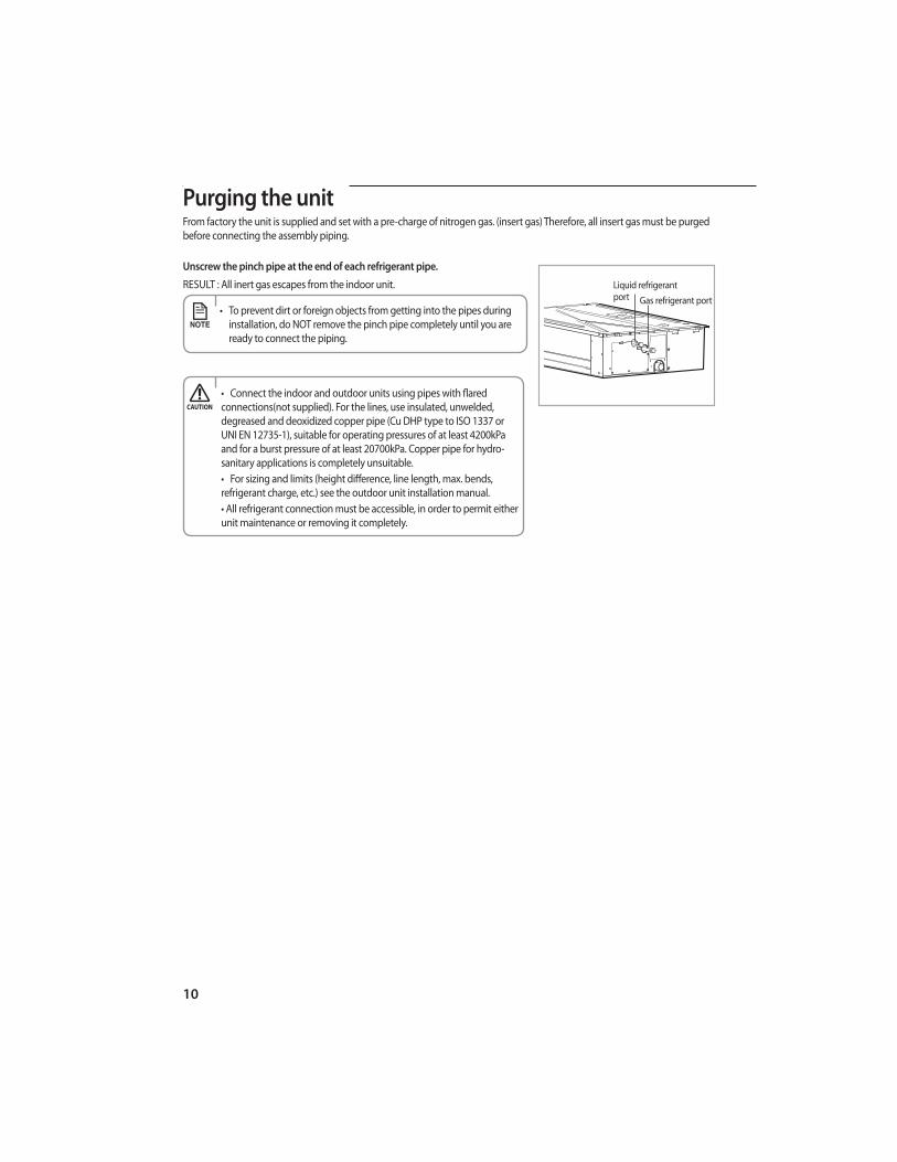
AAPurging the unitFrom factory the unit is supplied and set with a pre-charge of nitrogen gas. (insert gas) Therefore, all insert gas must be purged before connecting the assembly piping.
Unscrew the pinch pipe at the end of each refrigerant pipe.
RESULT : All inert gas escapes from the indoor unit.
ready to connect the piping.
Gas refrigerant portLiquid refrigerant port
connections(not supplied). For the lines, use insulated, unwelded, degreased and deoxidized copper pipe (Cu DHP type to ISO 1337 or UNI EN 12735-1), suitable for operating pressures of at least 4200kPa and for a burst pressure of at least 20700kPa. Copper pipe for hydro-sanitary applications is completely unsuitable.
refrigerant charge, etc.) see the outdoor unit installation manual.

11
AA
EN
GLIS
H
There are two refrigerant pipes of different diameters :
◆ A smaller one for the liquid refrigerant◆ A larger one for the gas refrigerant◆ The inside of copper pipe must be clean & has no dust
1. Remove the pinch pipe on the pipes and connect the assembly pipes to each pipe, tightening the nuts, first manually
and then with a torque wrench, a spanner applying the following torque.
2. Must use insulator which is thick enough to cover the refrigerant tube to protect the condensate water on the outside
of pipe falling onto the floor and the efficiency of the unit will be better.
3. Cut off any excess foam insulation.
4. Be sure that there must be no crack or wave on the bended area.
5. It would be necessary to double the insulation thickness(10mm or more) to prevent condensation even on the
insulator when if the installed area is warm and humid.
6. Do not use joints or extensions for the pipes that connect the indoor and outdoor unit. The only permitted connections
are those for which the units are designed.
Refrigerant oil
Spanner
Union
Torque wrench
Flare nut
Outer Diameter (D) Torque
ø6.35 mm(1/4”) 18(13.3)ø9.52 mm(3/8”) 42(31.0)
ø12.70 mm(1/2”) 55(40.6)ø15.88 mm(5/8”) 65(48.0)ø19.05 mm(3/4”) 100(73.8)
Connecting the refrigerant pipe
Liquid refrigerant port
Gas refrigerant port
Drain hose connection port
Slim Duct Type

12
Cutting/Flaring the pipes
1. Make sure that you have the required tools available. (pipe cutter, reamer, flaring tool and pipe holder)
2. If you wish to shorten the pipes, cut it with a pipe cutter, taking care to ensure that the cut edge remains at a 90° angle
with the side of the pipe. Refer to the illustrations below for examples of edges cut correctly and incorrectly.
3. To prevent any gas from leaking out, remove all burrs at the cut edge of the pipe, using a reamer.
4. Slide a flare nut on to the pipe and modify the flare.
5. Check that the flaring is correct, referring to the illustrations below for examples of incorrect flaring.
6. Align the pipes and tighten the flare nuts first manually and then with a torque wrench, applying the following torque.
Oblique Rough BurrPipe cutter
Pipe
Outer Diameter (D) Depth (A)
ø6.35 mm(1/4”) 0.051inch(1.3 mm)ø9.52 mm(3/8”) 0.071inch(1.8 mm)
ø12.70 mm(1/2”) 0.079inch(2.0 mm)ø15.88 mm(5/8”) 0.087inch(2.2 mm)ø19.05 mm(3/4”) 0.087inch(2.2 mm)Pipe Flare
ThicknessCrackedDamaged
SurfaceInclinedCorrect
Flare nut Pressure port cap Pressure portWrench
[inch(mm)]Wrench
[inch(mm)]Wrench
[inch(mm)]Wrench
[inch(mm)]Wrench
[inch(mm)]1/4" 0.67(17) 13.3(18) 0.91(23) 14.8(20) 0.71(18) 11.8~13.3(16~18) Allen(hex.) 0.2(5) 6.6(9) - 0.25(0.34)3/8" 0.87(22) 31.0(42) 0.91(23) 14.8(20) 0.71(18) 11.8~13.3(16~18) Allen(hex.) 0.2(5) 6.6(9) - 0.25(0.34)1/2" 1.02(26) 40.6(55) 1.14(29) 29.5(40) 0.71(18) 11.8~13.3(16~18) Allen(hex.) 0.2(5) 9.6(13) - 0.25(0.34)5/8" 1.14(29) 47.9(65) 1.14(29) 29.5(40) 0.71(18) 11.8~13.3(16~18) Allen(hex.) 0.2(5) 9.6(13) - 0.25(0.34)3/4" 1.42(36) 73.8(100) 1.50(38) 29.5(40) 0.71(18) 11.8~13.3(16~18) Allen(hex.) 0.2(5) 9.6(13) - 0.25(0.34)

13
EN
GLIS
H
Performing leak test & insulation
Once you have checked that there are no leaks in the system, you can insulate the piping and hose.
1 To avoid condensation problems, place T0.511inch(13mm) or thicker Acrylonitrile Butadien Rubber separately around each
refrigerant pipe.
2 Wind insulating tape around the pipes and drain hose avoiding to compress the insulation too much.
3 Finish wrapping insulating tape around the rest of the pipes leading to the outdoor unit.
4 The pipes and electrical cables connecting the indoor unit with the outdoor
unit must be fixed to the wall with suitable ducts.
5 Select the insulation of the refrigerant pipe. ◆ Insulate the gas side and liquid side pipe referring to the thickness
according to the pipe size. ◆ -
tion. If installing in a high humidity condition, use one grade thicker insulator by referring to the table below.
◆
Leak test
Insulation
No gap
NBR(T0.511inch(13mm)or thicker)
Indoor unit
the insulation
Insulation pipe
body without any gap.
◆ LEAK TEST WITH NITROGEN (before opening valves)
In order to detect basic refrigerant leaks, before recreating the vacuum and
recirculating the R-410A, it’s responsable of installer to pressurize the whole
system with nitrogen (using a cylinder with pressure reducer)
at a pressure above 40 bar (gauge).
◆ LEAK TEST WITH R-410A (after opening valves)
Before opening valves, discharge all the nitrogen into the system and create vacuum. After opening valves check
leaks using a leak detector for refrigerant R-410A.
Slim Duct Type

14
AA
◆ When installing insulation in places and conditions below, use the same insulation that is used for high humidity conditions.<Geological condition>
earth and sand.)<Operation purpose condition>- Restaurant ceiling, sauna, swimming pool etc.<Building construction condition>
e.g. The pipe installed at a corridor of a dormitory and studio or near an exit that opens and closes frequently.
PipePipe size
Insulation Type (Heating/Cooling)
Remarks
Standard High humidity
EPDM, NBR
inch mm inch mm inch mm
Liquid pipe Ø1/4~3/8 Ø6.35~9.52 9t 3/8 9t 3/8
Internal tempera-ture is higher than
248°F(120°C)
Ø1/2~3/4 Ø12.7~19.05 13t 1/2 13t 1/2
Gas pipe
Ø1/4 Ø6.35 13t 1/2 19t 3/4Ø3/8 Ø9.52
19t 3/4 25t 1Ø1/2 Ø12.70Ø5/8 Ø15.88Ø3/4 Ø19.05
Performing leak test & insulation

15
AA
EN
GLIS
H
Drainpipe and drain hose installation
Care must be taken when installing the drain hose for the indoor unit to ensure that any conden-sate water is correctly drained outside. The drain hose can be installed to the right of the base pan.
1 Installing the drain hose should be the shorter, the better.◆ In order to discharge condensation water, the drain hose should keep tilted. ◆ Fix the drain hose with Cable-Tie, so that it will not separate from the machine.◆ While using draining pump, connect the end with draining pump.
2 Insulate and fix the drain hose according to the figure.◆ Insert the drain hose to bottom of the outfall of water basin.◆ Lock steel ring of the drain hose according to the figure.◆ Wind and wrap steel ring and drain hose fully with thermal insulation sponge; fix both ends of external layer with ribbon for thermal insulation.◆ After being installed, drain hose must be insulated fully by heat insulating material. (To be pro-
Steel ring of drain hoseJoint of drain hose
Drain hose Drain hose
Fix with Cable-Tie
Indo
or u
nit
As shown in the figure, tighten steel ring of the drain hose.

16
AA
1. Install horizontal drainpipe with a slope of 1/100 or more and fix it by hanger space of 3.28~4.92ft(1.0~1.5m).
2.
3. Do not install the drainpipe to upward position. It may cause water flow back to the unit.
Without the drain pump
3.28~4.92ft
Horizontal drainpipemore than 1/100 slopeCeiling
HangerFlexible hose
With the drain pump1. The drain pipe should be installed within 11.8inch(300mm) to 21.7inch(550mm) from the flexible hose and
then lift down 0.79inch(20mm) or more.
2. Install horizontal drainpipe with a slope of 1/100 or more and fix it by hanger space of 3.28~4.92ft(1.0~1.5m).
3
4 The flexible hose should not be installed upward position, it may cause water flow back to the indoor unit.
(1~1.5m)
0.79inch(20mm) or more
7.9inch(200mm) or more Hanger
Within 11.8~21.7inch(300~550mm)
11.8inch(300mm) or less
Flexible hose
Horizontal drainpipemore than 1/100 slopeCeiling
Prepare a little water about 5 liter.
1 Pour water into the base pan in the indoor unit as shown in figure.
2 Confirm that the water flows out through the drain hose.
Testing the drainage
Drainpipe Connection
You may not need to install it if there were proper slope in the horizontal drainpipe.
(1~1.5m)
3.28~4.92ft
Drainpipe and drain hose installation
17
AA
EN
GLIS
H
Connecting the connection cord
When disconnecting the system, always disconnect the electric cables before disconnecting the refrigerant pipes.
the electric connections.
The indoor unit is powered by the outdoor unit by means of a H07 RN-F connection cable (or a more power model),
with insulation in synthetic rubber and jacket in polychloroprene(neoprene), in accordance with the requirements of standard EN 60335-2-40.
1. Remove the screw on the electrical component box and remove the cover plate.
2. Route the connection cord through the side of the indoor unit and connect the cable to terminals; refer to the figure below.
3. Route the other end of the cable to the outdoor unit through the ceiling & the hole on the wall.
4. Reassemble the electrical component box cover, carefully tightening the screw.

AA
18
Wiring and Communication Cable Connection
Connect the power cable, which is connected with the outdoor unit and supplied by another source, making sure that the power cable terminal should not be changed.
connected to the corresponding F3 and F4 terminal.
MAIN PCB
Indoor Unit
Outdoor Unit
L1 L2 Vc Vc Vw Vw F1 F2 V1 V2 F3 F4
V2
V1
L1 L2 L1 L2 F1 F2 F1 F2L1 L2
1 2
A
Display Unit(Optional)
CN51 BLK
Float Switch Drain Pump(Optional)
CN74 YEL
Between Indoor and Outdoor ommunication Terminal
Indoor Power Terminal
Wired Remote Controller
COM2(F3, F4)
CN31 RED
CN33 BLU
Connecting the connection cord
Main PowerSupply cable

19
EN
GLIS
H
Indoor Power supplyCommunication Cable
Power Supply Indoor Power cable0.75~1.5mm²,3wires 0.75~1.25mm²,2wires
Power supply cords of parts of appliances for outdoor use shall not be lighter than polychloroprene sheathed flexible cord. (Code designation IEC:60245 IEC 57 / CENELEC: H05RN-F or IEC:60245 IEC 66 / CENELEC: H07RN-F)
Since it has the external power supply, refer to the outdoor unit installation manual for MAIN POWER.
Between Indoor and Outdoor Connection cable Specifications(Common in use)
Terminal Block SPEC (Indoor)
When installing the indoor unit in a computer room, use the double shielded(Tape aluminum / polyester braid + copper)cable of FROHH2R type.
AC POWER : M4 SCREW
8.4 9.5
COMMUNICATION : M4 SCREW
8.4 9.5
1010
In case of extending the electric wire, please DO NOT use a round-shaped pressing socket.
- Incomplete wire connections can cause electric shock or a fire.
WARNING

20
AAIncreasing Fan Speed
1. Remove the screw on the electrical component box and remove the cover plate.
2. Adjust the DIP switch(SW05) on the main PCB to the “OFF” position.
Switch No. Switch Position Function
K3ON Normal speed
OFF High speed
K1 K2 K3 K4
SW05
3. Re-install the cover plate and join the removed screw.
External Static Pressure
External Static Pressure (mmAq) 1.0 2.0 3.0 4.0
AJ009JNLDCH 015201-14021C-200001-300000
015201-14023E-200001-300000
015201-140390-200001-300000
015203-1403F9-200001-300000
AJ012JNLDCH 015201-16025F-200001-300000
015201-160370-200001-300000
015203-160183-200001-300000
015203-1603CE-200001-300000
AJ018JNLDCH 011224-1940D5-200001-300000
011224-1940E6-200001-300000
011224-1940F7-200001-300000
011224-194208-200001-300000
❈ Mark " " is the basic model of this product.

21
AA
EN
GLIS
H
Assigning Address to Indoor Unit
1. Before installing the indoor unit,assign an address to the indoor unit according to the air conditioning system
plan.
2. The address of the indoor unit is assigned by adjusting MAIN(SW02) switch.
K1 K2 K3 K4 K5 K6 K7 K8 K9 K10K11 K12
3. The MAIN address is for communication between the indoor unit and the outdoor unit. Therefore, you must
set it to operate the air conditioner properly.
4. It is required to set the RMC address if you install the wired remote controller and/or the centralized controller.
5. If you install optional accessories such as the wired remote controller, centralized controller, etc. see an appro-
priate installation manual.
6. If an optional accessory is not installed, you do not have to set the RMC address. However, adjust K1 and K2
switches of the SW05 DIP switch to "ON" position in this case.
7. Set the MAIN address by adjusting the rotary switch(SW02) from 0 to 9. Each indoor unit connected to the
same outdoor unit must have different address.

22
AAAdditional Functions
SW05
No. Function ON OFF
SW05
K1 External room sensor Not use Use
K2 Centralized controller Not use Use
K3 Compensate RPM Standard Up
K4 Drain Pump Not use Use
K1 OFF
Thermo OFF Fan OFF
SW06
No. Function ON OFF
SW06
K5Indoor TemperatureCompensation for
Heating Mode+2°C +5°C
K6 Filter Time 1,000 hours 2,000 hours
K7 Hot Water Coil Not Use Use
K8 - - -
SW07
No. Function ON OFF
SW07
K9 - - -
K10 - - -
K11 External control Not Use Use
K12 External Control Output Thermal ON Operation ON

23
AA
EN
GLIS
H
Placing the Indoor Unit in Position
foam separately around each refrigerant pipe in the lower part of the indoor unit.
2. Wind insulating tape around the pipes, assembly cable and drain hose.
3. Place the resulting bundle carefully in the lower part of the
the indoor unit.
4unit to the right and left until you are sure that it is securely in place.
to the outdoor unit.
6. Using clamps (optionally supplied), attach the piping to the wall
indoor unit on the installation plate.
Installation plate
AA
24
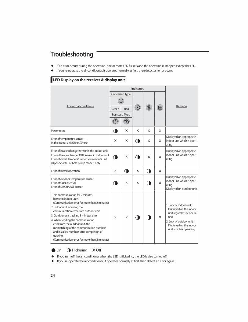
Troubleshooting
Abnormal conditions
Indicators
Remarks
Concealed Type
Green Red
Standard Type
Power reset X X X X
Error of temperature sensor in the indoor unit (Open/Short) X X X X
Displayed on appropriate indoor unit which is oper-ating
Error of heat exchanger sensor in the indoor unitError of heat exchanger OUT sensor in indoor unit Error of outlet temperature sensor in indoor unit (Open/Short): For heat pump models only
X X X
Displayed on appropriate indoor unit which is oper-ating
Error of mixed operation X X X
Error of outdoor temperature sensor Error of COND sensor Error of DISCHARGE sensor
X X X
Displayed on appropriate indoor unit which is oper-ating Displayed on outdoor unit
1. No communication for 2 minutes between indoor units (Communication error for more than 2 minutes)
communication error from outdoor unit
3. Outdoor unit tracking 3 minutes error4. When sending the communication
error from the outdoor unit, the mismatching of the communication numbers and installed numbers after completion of tracking. (Communication error for more than 2 minutes)
X X X
1. Error of indoor unit: Displayed on the indoor unit regardless of opera-tion
2. Error of outdoor unit: Displayed on the indoor unit which is operating
◆ If you turn off the air conditioner when the LED is flickering, the LED is also turned off.◆ If you re-operate the air conditioner, it operates normally at first, then detect an error again.
● On Flickering X Off
◆ If an error occurs during the operation, one or more LED flickers and the operation is stopped except the LED.◆ If you re-operate the air conditioner, it operates normally at first, then detect an error again.
LED Display on the receiver & display unit

25
EN
GLIS
H
◆ If you turn off the air conditioner when the LED is flickering, the LED is also turned off.◆ If you re-operate the air conditioner, it operates normally at first, then detect an error again.
● On Flickering X Off
Abnormal conditions
Indicators
Remarks
Concealed Type
Green Red
Standard Type
Self-diagnostic error (including the indoor unit not detected)
X X
Displayed on appropriate indoor unit which is oper-ating Displayed on outdoor unit
5. Breakaway of COND MID sensor 6. 2nd detection of refrigerant completely leak 7. 2nd detection of high temperature COND 8. 2nd detection of high temperature
DISCHARGE 9. COMP DOWN due to 2nd detection of low
pressure switch
11. Compressor down due to 6th detection of freezing
12. Self-diagnosis of condensation sensor (G8, G9)
13. Compressor down due to condensation ratio control
X X
Displayed on appropriate indoor unit which is oper-ating Displayed on outdoor unit
Error of float switch X X X
Error of setting option switches for optional accessories X X X
EEPROM error X X
EEPROM option error X
LED Display on the receiver & display unit


Air Conditionerinstallation manual
imagine the possibilitiesThank you for purchasing this Samsung product.
This manual is made with 100% recycled paper.
Duct Type Series
AJ✴✴✴JNLDCH
DB68-04995A-00EN ES FR