Embed Size (px)
Citation preview
5JW-28199-20
FJR1300N
OWNER’S MANUAL
PRINTED ON RECYCLED PAPER
YAMAHA MOTOR CO., LTD.
PRINTED IN JAPAN2001 · 3 - 0.3 × 1 CR
(E)

H_5KS_Toc0.fm Page 2 Monday, August 21, 2000 11:11 AM

EAU00000
1-INTRODUCTION
Congratulations on your purchase of the Yamaha FJR1300. This model is the resultof Yamaha’s vast experience in the production of fine sporting, touring, and paceset-ting racing machines. It represents the high degree of craftsmanship and reliabilitythat have made Yamaha a leader in these fields.
This manual will give you an understanding of the operation, inspection, and basicmaintenance of this motorcycle. If you have any questions concerning the operationor maintenance of your motorcycle, please consult a Yamaha dealer.
E_5jw.book Page 1 Friday, March 30, 2001 2:14 PM
EAU00005IMPORTANT MANUAL INFORMATION
Particularly important information is distinguished in this manual by the following notations:
The Safety Alert Symbol means ATTENTION! BECOME ALERT! YOUR SAFETY ISINVOLVED!
WARNING Failure to follow WARNING instructions could result in severe injury or death to themotorcycle operator, a bystander, or a person inspecting or repairing themotorcycle.
CAUTION: A CAUTION indicates special precautions that must be taken to avoid damage to themotorcycle.
NOTE: A NOTE provides key information to make procedures easier or clearer.
NOTE:_
● This manual should be considered a permanent part of this motorcycle and should remainwith it even if the motorcycle is subsequently sold.
● Yamaha continually seeks advancements in product design and quality. Therefore, whilethis manual contains the most current product information available at the time of printing,there may be minor discrepancies between your motorcycle and this manual. If you haveany questions concerning this manual, please consult your Yamaha dealer.
_
E_5jw.book Page 1 Friday, March 30, 2001 2:14 PM
IMPORTANT MANUAL INFORMATIONEW000002
WARNING_
PLEASE READ THIS MANUAL CAREFULLY AND COMPLETELY BEFORE OPERATINGTHIS MOTORCYCLE. _
E_5jw.book Page 2 Friday, March 30, 2001 2:14 PM
IMPORTANT MANUAL INFORMATION
EAU03337
FJR1300NOWNER’S MANUAL
© 2001 by Yamaha Motor Co., Ltd.1st Edition, March 2001
All rights reserved.Any reprinting or unauthorized usewithout the written permission of
Yamaha Motor Co., Ltd.is expressly prohibited.
Printed in Japan.
E_5jw.book Page 3 Friday, March 30, 2001 2:14 PM

TABLE OF CONTENTS
1 SAFETY INFORMATION 1
2 DESCRIPTION 2
3 INSTRUMENT AND CONTROL FUNCTIONS 3
4 PRE-OPERATION CHECKS 4
5 OPERATION AND IMPORTANT RIDING POINTS 5
6 PERIODIC MAINTENANCE AND MINOR REPAIR 6
7 MOTORCYCLE CARE AND STORAGE 7
8 SPECIFICATIONS 8
9 CONSUMER INFORMATION 9
INDEX
EAU00009
E_5jw.book Page 1 Friday, March 30, 2001 2:14 PM

E_5jw.book Page 2 Friday, March 30, 2001 2:14 PM
SAFETY INFORMATION
1
Safe riding .......................................................................................... 1-1Protective apparel .............................................................................. 1-3Modifications ...................................................................................... 1-3Loading and accessories ................................................................... 1-3Gasoline and exhaust gas.................................................................. 1-5Location of important labels .............................................................. 1-7
E_5jw.book Page 1 Friday, March 30, 2001 2:14 PM
1
1-1
EAU00014*
1-SAFETY INFORMATION
MOTORCYCLES ARE SINGLE TRACK VEHICLES. THEIR SAFE USE AND OPERATION ARE DE-PENDENT UPON THE USE OF PROPER RIDING TECHNIQUES AS WELL AS THE EXPERTISE OFTHE OPERATOR. EVERY OPERATOR SHOULD KNOW THE FOLLOWING REQUIREMENTS BE-FORE RIDING THIS MOTORCYCLE.HE OR SHE SHOULD:1. OBTAIN THOROUGH INSTRUCTIONS FROM A COMPETENT SOURCE ON ALL ASPECTS OF
MOTORCYCLE OPERATION.2. OBSERVE THE WARNINGS AND MAINTENANCE REQUIREMENTS IN THE OWNER’S MANUAL.3. OBTAIN QUALIFIED TRAINING IN SAFE AND PROPER RIDING TECHNIQUES.4. OBTAIN PROFESSIONAL TECHNICAL SERVICE AS INDICATED BY THE OWNER’S MANUAL
AND/OR WHEN MADE NECESSARY BY MECHANICAL CONDITIONS.
Safe riding
1. Always make pre-operation checks. Careful checks may help prevent an accident.2. This motorcycle is designed to carry the operator and a passenger.3. The failure of motorists to detect and recognize motorcycles in traffic is the predominating cause of
automobile/motorcycle accidents. Many accidents have been caused by an automobile driver whodid not see the motorcycle. Making yourself conspicuous appears to be very effective in reducing thechance of this type of accident.
Therefore:a. Wear a brightly colored jacket.b. Use extra caution when you are approaching and passing through intersections, since intersec-
tions are the most likely places for motorcycle accidents to occur.c. Ride where other motorists can see you. Avoid riding in another motorist’s blind spot.
E_5jw.book Page 1 Friday, March 30, 2001 2:14 PM

SAFETY INFORMATION
1
1-2
4. Many accidents involve inexperienced operators. In fact, many operators who have been involved inaccidents do not even have a current motorcycle license.a. Make sure that you are qualified and that you only lend your motorcycle to other qualified opera-
tors.b. Know your skills and limits. Staying within your limits may help you to avoid an accident.c. We recommend that you practice riding your motorcycle where there is no traffic until you have
become thoroughly familiar with the motorcycle and all of its controls.5. Many accidents have been caused by error of the motorcycle operator. A typical error made by the
operator is veering wide on a turn due to EXCESSIVE SPEED or undercornering (insufficient leanangle for the speed).a. Always obey the speed limit and never travel faster than warranted by road and traffic conditions.b. Always signal before turning or changing lanes. Make sure that other motorists can see you.
6. The posture of the operator and passenger is important for proper control.a. The operator should keep both hands on the handlebar and both feet on the operator footrests
during operation to maintain control of the motorcycle.b. The passenger should always hold onto the operator, the seat strap or grab bar, if equipped, with
both hands and keep both feet on the passenger footrests.c. Never carry a passenger unless he or she can firmly place both feet on the passenger footrests.
7. Never ride under the influence of alcohol or other drugs.8. This motorcycle is designed for on-road use only. It is not suitable for off-road use.
E_5jw.book Page 2 Friday, March 30, 2001 2:14 PM

SAFETY INFORMATION
1
1-3
Protective apparel
The majority of fatalities from motorcycle accidents are the result of head injuries. The use of a safetyhelmet is the single most critical factor in the prevention or reduction of head injuries.1. Always wear an approved helmet.2. Wear a face shield or goggles. Wind in your unprotected eyes could contribute to an impairment of vi-
sion that could delay seeing a hazard.3. The use of a jacket, heavy boots, trousers, gloves, etc., is effective in preventing or reducing abra-
sions or lacerations.4. Never wear loose-fitting clothes, otherwise they could catch on the control levers, footrests, or wheels
and cause injury or an accident.5. Never touch the engine or exhaust system during or after operation. They become very hot and can
cause burns. Always wear protective clothing that covers your legs, ankles, and feet.6. A passenger should also observe the above precautions.
Modifications
Modifications made to this motorcycle not approved by Yamaha, or the removal of original equipment,may render the motorcycle unsafe for use and may cause severe personal injury. Modifications may alsomake your motorcycle illegal to use.
Loading and accessories
Adding accessories or cargo to your motorcycle can adversely affect stability and handling if the weightdistribution of the motorcycle is changed. To avoid the possibility of an accident, use extreme cautionwhen adding cargo or accessories to your motorcycle. Use extra care when riding a motorcycle that hasadded cargo or accessories. Here are some general guidelines to follow if loading cargo or adding ac-cessories to your motorcycle:
E_5jw.book Page 3 Friday, March 30, 2001 2:14 PM

SAFETY INFORMATION
1
1-4
Loading
The total weight of the operator, passenger, accessories and cargo must not exceed the maximum loadlimit of 208 kg. When loading within this weight limit, keep the following in mind:1. Cargo and accessory weight should be kept as low and close to the motorcycle as possible. Make
sure to distribute the weight as evenly as possible on both sides of the motorcycle to minimize imbal-ance or instability.
2. Shifting weights can create a sudden imbalance. Make sure that accessories and cargo are securelyattached to the motorcycle before riding. Check accessory mounts and cargo restraints frequently.
3. Never attach any large or heavy items to the handlebar, front fork, or front fender. These items, in-cluding such items as sleeping bags, duffel bags, or tents, can create unstable handling or a slowsteering response.
Accessories
Genuine Yamaha accessories have been specifically designed for use on this motorcycle. SinceYamaha cannot test all other accessories that may be available, you must personally be responsible forthe proper selection, installation and use of non-Yamaha accessories. Use extreme caution when select-ing and installing any accessories.Keep the following guidelines in mind, as well as those provided under “Loading” when mounting acces-sories.1. Never install accessories or carry cargo that would impair the performance of your motorcycle. Care-
fully inspect the accessory before using it to make sure that it does not in any way reduce groundclearance or cornering clearance, limit suspension travel, steering travel or control operation, or ob-scure lights or reflectors.
E_5jw.book Page 4 Friday, March 30, 2001 2:14 PM

SAFETY INFORMATION
1
1-5
a. Accessories fitted to the handlebar or the front fork area can create instability due to improperweight distribution or aerodynamic changes. If accessories are added to the handlebar or frontfork area, they must be as lightweight as possible and should be kept to a minimum.
b. Bulky or large accessories may seriously affect the stability of the motorcycle due to aerodynamiceffects. Wind may attempt to lift the motorcycle, or the motorcycle may become unstable in crosswinds. These accessories may also cause instability when passing or being passed by large ve-hicles.
c. Certain accessories can displace the operator from his or her normal riding position. This improp-er position limits the freedom of movement of the operator and may limit control ability, therefore,such accessories are not recommended.
2. Use caution when adding electrical accessories. If electrical accessories exceed the capacity of themotorcycle’s electrical system, an electric failure could result, which could cause a dangerous loss oflights or engine power.
Gasoline and exhaust gas
1. GASOLINE IS HIGHLY FLAMMABLE:a. Always turn the engine off when refueling.b. Take care not to spill any gasoline on the engine or exhaust system when refueling.c. Never refuel while smoking or in the vicinity of an open flame.
2. Never start the engine or let it run for any length of time in a closed area. The exhaust fumes are poi-sonous and may cause loss of consciousness and death within a short time. Always operate yourmotorcycle in an area that has adequate ventilation.
E_5jw.book Page 5 Friday, March 30, 2001 2:14 PM
SAFETY INFORMATION
1
1-6
3. Always turn the engine off before leaving the motorcycle unattended and remove the key from themain switch. When parking the motorcycle, note the following:a. The engine and exhaust system may be hot, therefore, park the motorcycle in a place where pe-
destrians or children are not likely to touch these hot areas.b. Do not park the motorcycle on a slope or soft ground, otherwise it may fall over.c. Do not park the motorcycle near a flammable source (e.g., a kerosene heater, or near an open
flame), otherwise it could catch fire.4. When transporting the motorcycle in another vehicle, make sure that it is kept upright. If the motor-
cycle should lean over, gasoline may leak out of the fuel tank.5. If you should swallow any gasoline, inhale a lot of gasoline vapor, or allow gasoline to get into your
eyes, see your doctor immediately. If any gasoline spills on your skin or clothing, immediately washthe affected area with soap and water and change your clothes.
E_5jw.book Page 6 Friday, March 30, 2001 2:14 PM

SAFETY INFORMATION
1
1-7
EAU02977
Location of important labels Please read the following important labels carefully before operating this motorcycle.
WARNINGBefore you operate this vehicle, read the owner’s manual.
English 3HP-21568-E0
1
2
4AA-22259-40
E_5jw.book Page 7 Friday, March 30, 2001 2:14 PM

DESCRIPTION
2
Left view ............................................................................................. 2-1Right view........................................................................................... 2-2Controls and instruments ................................................................... 2-3
E_5jw.book Page 1 Friday, March 30, 2001 2:14 PM

2-1
2
EAU00026
2-DESCRIPTION
Left view
1. Fuse box (page 6-30)2. Front fork spring preload adjusting bolt (page 3-11)3. Front fork rebound damping force
adjusting knob (page 3-12)4. Engine oil filler cap (page 6-10)5. Owner’s tool kit (page 6-1)6. Rider seat (page 3-10)7. Passenger seat (page 3-10)8. Rear carrier9. Final gear oil filler bolt (page 6-12)
10. Final gear oil drain bolt (page 6-12)11. Shock absorber assembly rebound
damping force adjusting knob (page 3-14)12. Shock absorber assembly spring preload
adjusting lever (page 3-13)13. Air filter element (page 6-15)14. Shift pedal (page 3-6)15. Engine oil filter cartridge (page 6-10)16. Engine oil level check window (page 6-10)
E_5jw.book Page 1 Friday, March 30, 2001 2:14 PM

DESCRIPTION
2-2
2
Right view
17. Passenger footrest18. Coolant reservoir (page 6-13)19. Battery (page 6-29)20. Windshield21. Main fuse and fuel injection system fuse (page 6-30)22. Front fork compression damping force
adjusting screw (page 3-12)23. Brake pedal (page 3-7)24. Rider footrest
E_5jw.book Page 2 Friday, March 30, 2001 2:14 PM

DESCRIPTION
2-3
2
Controls and instruments
1. Clutch lever (page 3-6)2. Left handlebar switches (page 3-5)3. Tachometer (page 3-3)4. Speedometer (page 3-3)5. Multi-function display (page 3-3)6. Right handlebar switches (page 3-5)7. Brake lever (page 3-7)8. Throttle grip (page 6-17)9. Main switch/steering lock (page 3-1)
E_5jw.book Page 3 Friday, March 30, 2001 2:14 PM

INSTRUMENT AND CONTROL FUNCTIONS
3
Main switch/steering lock .................................................................. 3-1Indicator and warning lights ............................................................. 3-2Speedometer ..................................................................................... 3-3Tachometer ....................................................................................... 3-3Multi-function display ......................................................................... 3-3Handlebar switches ........................................................................... 3-5Clutch lever ....................................................................................... 3-6Shift pedal ......................................................................................... 3-6Brake lever ........................................................................................ 3-7Brake pedal ....................................................................................... 3-7Fuel tank cap ..................................................................................... 3-8Fuel ................................................................................................... 3-9Catalytic converter ............................................................................ 3-9Seats ................................................................................................ 3-10Storage compartment ..................................................................... 3-11Adjusting the front fork .................................................................... 3-11Adjusting the shock absorber assembly .......................................... 3-13Matching the front and rear suspension settings ............................ 3-15Locks for the optional side cases and travel trunk ........................... 3-16Sidestand ........................................................................................ 3-16Ignition circuit cut-off system ........................................................... 3-17
E_5jw.book Page 1 Friday, March 30, 2001 2:14 PM
3-1
3
EAU00027
3-INSTRUMENT AND CONTROL FUNCTIONS
EAU00029
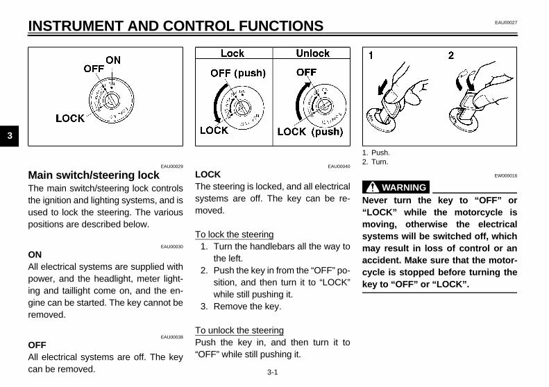
Main switch/steering lock The main switch/steering lock controlsthe ignition and lighting systems, and isused to lock the steering. The variouspositions are described below.
EAU00030
ONAll electrical systems are supplied withpower, and the headlight, meter light-ing and taillight come on, and the en-gine can be started. The key cannot beremoved.
EAU00038
OFFAll electrical systems are off. The keycan be removed.
EAU00040
LOCKThe steering is locked, and all electricalsystems are off. The key can be re-moved.
To lock the steering1. Turn the handlebars all the way to
the left.2. Push the key in from the “OFF” po-
sition, and then turn it to “LOCK”while still pushing it.
3. Remove the key.
To unlock the steeringPush the key in, and then turn it to“OFF” while still pushing it.
EW000016
WARNING_
Never turn the key to “OFF” or“LOCK” while the motorcycle ismoving, otherwise the electricalsystems will be switched off, whichmay result in loss of control or anaccident. Make sure that the motor-cycle is stopped before turning thekey to “OFF” or “LOCK”. _
1. Push.2. Turn.
E_5jw.book Page 1 Friday, March 30, 2001 2:14 PM

INSTRUMENT AND CONTROL FUNCTIONS
3-2
3
EAU03034
Indicator and warning lights
EAU04121
Turn signal indicator lights “ ” and “ ” The corresponding indicator light flash-es when the turn signal switch ispushed to the left or right.
EAU00061
Neutral indicator light “ ” This indicator light comes on when thetransmission is in the neutral position.
EAU00063
High beam indicator light “ ” This indicator light comes on when thehigh beam of the headlight is switchedon.
EAU03201
Oil level warning light “ ” This warning light comes on when theengine oil level is low.The electrical circuit of the warning lightcan be checked according to the fol-lowing procedure.
1. Set the engine stop switch to “ ”and turn the key to “ON”.
2. Shift the transmission into the neu-tral position or pull the clutch lever.
3. Push the start switch. If the warninglight does not come on while push-ing the start switch, have a Yamahadealer check the electrical circuit.
NOTE:_
Even if the oil level is sufficient, thewarning light may flicker when riding ona slope or during sudden accelerationor deceleration, but this is not a mal-function. _
EAU03192
Engine trouble warning light “ ” This warning light comes on or flasheswhen an electrical circuit monitoringthe engine is defective. When this oc-curs, have the Yamaha dealer checkthe self-diagnosis system.The electrical circuit of the warning lightcan be checked according to the fol-lowing procedure.
1. Set the engine stop switch to “ ”. 2. Turn the key to “ON”. If the warn-
ing light does not come on, have aYamaha dealer check the electri-cal circuit.
1. Left turn signal indicator light “ ”2. Right turn signal indicator light “ ”3. Neutral indicator light “ ”4. High beam indicator light “ ”5. Oil level warning light “ ”6. Engine trouble warning light “ ”
E_5jw.book Page 2 Friday, March 30, 2001 2:14 PM

INSTRUMENT AND CONTROL FUNCTIONS
3-3
3
EAU04031
Speedometer The speedometer shows the ridingspeed.
EAU00101
Tachometer The electric tachometer allows the riderto monitor the engine speed and keep itwithin the ideal power range.
EC000003
CAUTION:_
Do not operate the engine in the ta-chometer red zone.Red zone: 9,000 r/min and above _
EAU04095
Multi-function display The multi-function display is equippedwith the following:
● a fuel gauge● a coolant temperature gauge● an odometer (which shows the to-
tal distance traveled)● two tripmeters (which show the
distance traveled since they werelast set to zero)
● a fuel reserve tripmeter (whichshows the distance traveled on thefuel reserve)
1. Tachometer2. Speedometer3. Multi-function display
1. Tachometer2. Tachometer red zone
1. Multi-function display2. “SELECT” button3. “RESET” button
E_5jw.book Page 3 Friday, March 30, 2001 2:14 PM

INSTRUMENT AND CONTROL FUNCTIONS
3-4
3
● a selfdiagnosis device● a clock
Odometer and tripmeter modesPushing the “SELECT” button switchesthe display between the odometermode “ODO” and the tripmeter modes“TRIP” in the following order:ODO → TRIP (top) → TRIP (bottom)→ODO
When approximately 5 L of fuel re-mains in the fuel tank, the display willautomatically change to the fuel re-serve tripmeter mode “TRIP F” andstart counting the distance traveledfrom that point. In that case, pushingthe “SELECT” button switches the dis-play between the various tripmeter andodometer modes in the following order:TRIP F → TRIP (top) → TRIP (bottom)→ ODO → TRIP F
To reset a tripmeter, select it by push-ing the “SELECT” button, and thenpush the “RESET” button for at leastone second. If you do not reset the fuelreserve tripmeter manually, it will resetitself automatically and the display willreturn to the prior mode after refuelingand traveling 5 km.
Self-diagnosis deviceThis model is equipped with a self-di-agnosis device for various electrical cir-cuits.If any of those circuits are defective,the clock will indicate a two-digit errorcode (e.g., 11, 12, 13).If the clock indicates such an errorcode, note the code number, and thenhave a Yamaha dealer check themotorcycle.
ECA00100
CAUTION:_
If the clock indicates an error code,the motorcycle should be checkedas soon as possible in order toavoid engine damage. _
Clock modeTo set the clock:
1. Push the “SELECT” button and“RESET” button together for atleast two seconds.
2. When the hour digits start flashing,push the “RESET” button to setthe hours.
3. Push the “SELECT” button, andthe minute digits will start flashing.
4. Push the “RESET” button to setthe minutes.
5. Push the “SELECT” button andthen release it to start the clock.
E_5jw.book Page 4 Friday, March 30, 2001 2:14 PM
INSTRUMENT AND CONTROL FUNCTIONS
3-5
3
EAU00118
Handlebar switches
EAU00119
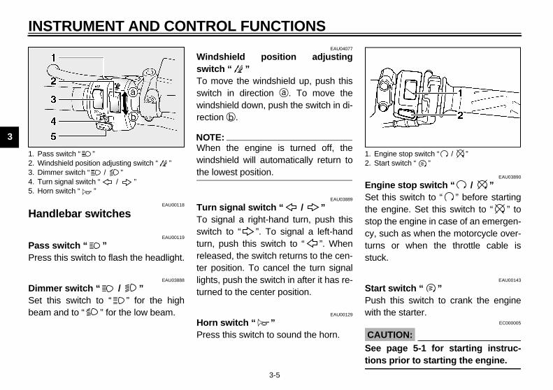
Pass switch “ ” Press this switch to flash the headlight.
EAU03888
Dimmer switch “ / ” Set this switch to “ ” for the highbeam and to “ ” for the low beam.
EAU04077
Windshield position adjustingswitch “ ” To move the windshield up, push thisswitch in direction a. To move thewindshield down, push the switch in di-rection b.
NOTE:_
When the engine is turned off, thewindshield will automatically return tothe lowest position. _
EAU03889
Turn signal switch “ / ” To signal a right-hand turn, push thisswitch to “ ”. To signal a left-handturn, push this switch to “ ”. Whenreleased, the switch returns to the cen-ter position. To cancel the turn signallights, push the switch in after it has re-turned to the center position.
EAU00129
Horn switch “ ” Press this switch to sound the horn.
EAU03890
Engine stop switch “ / ” Set this switch to “ ” before startingthe engine. Set this switch to “ ” tostop the engine in case of an emergen-cy, such as when the motorcycle over-turns or when the throttle cable isstuck.
EAU00143
Start switch “ ” Push this switch to crank the enginewith the starter.
EC000005
CAUTION:_
See page 5-1 for starting instruc-tions prior to starting the engine. _
1. Pass switch “ ”2. Windshield position adjusting switch “ ”3. Dimmer switch “ / ”4. Turn signal switch “ / ”5. Horn switch “ ”
1. Engine stop switch “ / ”2. Start switch “ ”
E_5jw.book Page 5 Friday, March 30, 2001 2:14 PM

INSTRUMENT AND CONTROL FUNCTIONS
3-6
3
EAU00153
Clutch lever The clutch lever is located at the lefthandlebar grip. To disengage theclutch, pull the lever toward the handle-bar grip. To engage the clutch, releasethe lever. The lever should be pulledrapidly and released slowly for smoothclutch operation.
The clutch lever is equipped with aclutch lever position adjusting dial. Toadjust the distance between the clutchlever and the handlebar grip, turn theadjusting dial while holding the leverpushed away from the handlebar grip.Make sure that the appropriate settingon the adjusting dial is aligned with thearrow mark on the clutch lever.The clutch lever is equipped with aclutch switch, which is part of the igni-tion circuit cut-off system. (Seepage 3-17 for an explanation of the ig-nition circuit cut-off system.)
EAU00157
Shift pedal The shift pedal is located on the leftside of the engine and is used in com-bination with the clutch lever whenshifting the gears of the 5-speed con-stant-mesh transmission equipped onthis motorcycle.
1. Clutch lever2. Arrow mark3. Clutch lever position adjusting diala. Distance between clutch lever and handlebar
grip
1. Shift pedal
E_5jw.book Page 6 Friday, March 30, 2001 2:14 PM

INSTRUMENT AND CONTROL FUNCTIONS
3-7
3
EAU00161
Brake lever The brake lever is located at the righthandlebar grip. To apply the frontbrake, pull the lever toward the handle-bar grip.
The brake lever is equipped with a po-sition adjusting dial. To adjust the dis-tance between the brake lever and thehandlebar grip, turn the adjusting dialwhile holding the lever pushed awayfrom the handlebar grip. Make sure thatthe appropriate setting on the adjustingdial is aligned with the arrow mark onthe brake lever.
EAU00162
Brake pedal The brake pedal is on the right side ofthe motorcycle. To apply the rearbrake, press down on the brake pedal.
1. Brake lever position adjusting dial2. Arrow mark3. Brake levera. Distance between brake lever and handlebar
grip
1. Brake pedal
E_5jw.book Page 7 Friday, March 30, 2001 2:14 PM

INSTRUMENT AND CONTROL FUNCTIONS
3-8
3
EAU04068
Fuel tank cap
To open the fuel tank capOpen the fuel tank cap lock cover, in-sert the key into the lock, and then turnit 1/4 turn clockwise. The lock will be re-leased and the fuel tank cap can beopened.
To close the fuel tank cap1. Push the fuel tank cap into posi-
tion with the key inserted in thelock.
2. Remove the key, and then closethe lock cover.
NOTE:_
The fuel tank cap cannot be closed un-less the key is in the lock. In addition,the key cannot be removed if the cap isnot properly closed and locked. _
EWA00025
WARNING_
Make sure that the fuel tank cap isproperly closed before riding. _
1. Fuel tank cap lock cover2. Unlock.
E_5jw.book Page 8 Friday, March 30, 2001 2:14 PM

INSTRUMENT AND CONTROL FUNCTIONS
3-9
3
EAU03753
Fuel Make sure that there is sufficient fuel inthe tank. Fill the fuel tank to the bottomof the filler tube as shown.
EW000130
WARNING_
● Do not overfill the fuel tank, oth-erwise it may overflow when thefuel warms up and expands.
● Avoid spilling fuel on the hotengine.
_
EAU00185
CAUTION:_
Immediately wipe off spilled fuelwith a clean, dry, soft cloth, sincefuel may deteriorate painted surfac-es or plastic parts. _
EAU00192*
EAU01084
Catalytic converter This motorcycle is equipped with a cat-alytic converter in the exhaust cham-ber.
EW000128
WARNING_
The exhaust system is hot after op-eration. Make sure that the exhaustsystem has cooled down before do-ing any maintenance work. _
EC000114
CAUTION:_
The following precautions must beobserved to prevent a fire hazard orother damages.
● Use only unleaded gasoline.The use of leaded gasoline willcause unrepairable damage tothe catalytic converter.
● Never park the motorcycle nearpossible fire hazards such asgrass or other materials thateasily burn.
● Do not allow the engine to idletoo long.
_
1. Fuel tank filler tube2. Fuel level
Recommended fuel:Unleaded fuel only
Fuel tank capacity:Total amount:
25 LReserve amount:
5 L
E_5jw.book Page 9 Friday, March 30, 2001 2:14 PM
INSTRUMENT AND CONTROL FUNCTIONS
3-10
3
EAU03945
Seats
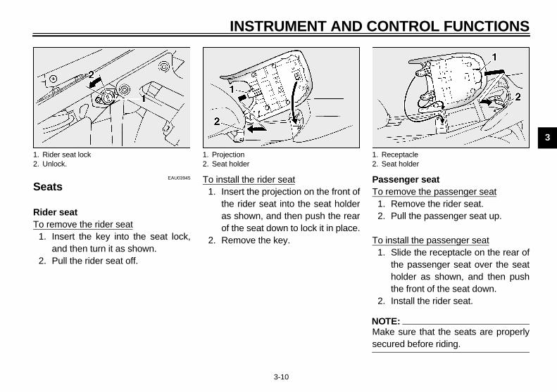
Rider seatTo remove the rider seat
1. Insert the key into the seat lock,and then turn it as shown.
2. Pull the rider seat off.
To install the rider seat1. Insert the projection on the front of
the rider seat into the seat holderas shown, and then push the rearof the seat down to lock it in place.
2. Remove the key.
Passenger seatTo remove the passenger seat
1. Remove the rider seat.2. Pull the passenger seat up.
To install the passenger seat1. Slide the receptacle on the rear of
the passenger seat over the seatholder as shown, and then pushthe front of the seat down.
2. Install the rider seat.
NOTE:_
Make sure that the seats are properlysecured before riding. _
1. Rider seat lock2. Unlock.
1. Projection2. Seat holder
1. Receptacle2. Seat holder
E_5jw.book Page 10 Friday, March 30, 2001 2:14 PM

INSTRUMENT AND CONTROL FUNCTIONS
3-11
3
EAU01242
Storage compartment The storage compartment is locatedunder the passenger seat. (Seepage 3-10 for passenger seat openingand closing procedures.)
EWA00005
WARNING_
● Do not exceed the load limit of3 kg for the storage compart-ment.
● Do not exceed the maximumload of 208 kg for the vehicle.
_
EAU03949*
Adjusting the front fork This front fork is equipped with springpreload adjusting bolts, rebound damp-ing force adjusting knobs and compres-sion damping force adjusting screws.
EW000035
WARNING_
Always adjust both fork legs equal-ly, otherwise poor handling and lossof stability may result. _ Spring preload
To increase the spring preload andthereby harden the suspension, turnthe adjusting bolt on each fork leg in di-rection a. To decrease the springpreload and thereby soften the suspen-sion, turn the adjusting bolt on eachfork leg in direction b.
1. Rebound damping force adjusting knob2. Spring preload adjusting bolt
E_5jw.book Page 11 Friday, March 30, 2001 2:14 PM

INSTRUMENT AND CONTROL FUNCTIONS
3-12
3
NOTE:_
Align the appropriate groove on the ad-justing mechanism with the top of thefront fork cap bolt. _
CI-01E
Rebound damping forceTo increase the rebound dampingforce and thereby harden the rebounddamping, turn the adjusting knob oneach fork leg in direction a. To de-crease the rebound damping force andthereby soften the rebound damping,turn the adjusting knob on each fork legin direction b.CI-09E
Compression damping forceTo increase the compression dampingforce and thereby harden the compres-sion damping, turn the adjusting screwon each fork leg in direction a. To de-crease the compression damping forceand thereby soften the compressiondamping, turn the adjusting screw oneach fork leg in direction b.CI-02E
1. Current setting2. Front fork cap bolt
HardStan-dard
Soft
Setting 1 2 3 4 5 6
Minimum (soft) 17 clicks in direction b*
Standard 12 clicks in direction b*
Maximum (hard) 1 click in direction b*
* With the adjusting knob fully turned in direction a
1. Compression damping force adjusting screw
Minimum (soft) 21 clicks in direction b*
Standard 12 clicks in direction b*
Maximum (hard) 1 click in direction b*
* With the adjusting screw fully turned in direction a
E_5jw.book Page 12 Friday, March 30, 2001 2:14 PM

INSTRUMENT AND CONTROL FUNCTIONS
3-13
3
EC000015
CAUTION:_
Never attempt to turn an adjustingmechanism beyond the maximumor minimum settings. _
NOTE:_
Although the total number of clicks of adamping force adjusting mechanismmay not exactly match the above spec-ifications due to small differences inproduction, the actual number of clicksalways represents the entire adjustingrange. To obtain a precise adjustment,it would be advisable to check the num-ber of clicks of each damping force ad-justing mechanism and to modify thespecifications as necessary. _
EAU03950
Adjusting the shock absorber assembly This shock absorber assembly isequipped with a spring preload adjust-ing lever and a rebound damping forceadjusting knob.
EC000015
CAUTION:_
Never attempt to turn an adjustingmechanism beyond the maximumor minimum settings. _ Spring preload
For riding solo, move the spring pre-load adjusting lever to “SOFT”. Forriding with a passenger, move thespring preload adjusting lever to“HARD”.
1. Spring preload adjusting levera. “HARD”b. “SOFT”
E_5jw.book Page 13 Friday, March 30, 2001 2:14 PM

INSTRUMENT AND CONTROL FUNCTIONS
3-14
3
Rebound damping forceTo increase the rebound dampingforce and thereby harden the rebounddamping, turn the adjusting knob in di-rection a. To decrease the rebounddamping force and thereby soften therebound damping, turn the adjustingknob in direction b.CI-09E
EAU00315
WARNING_
This shock absorber contains high-ly pressurized nitrogen gas. Forproper handling, read and under-stand the following information be-fore handling the shock absorber.The manufacturer cannot be held re-sponsible for property damage orpersonal injury that may result fromimproper handling.
● Do not tamper with or attempt toopen the gas cylinder.
● Do not subject the shock ab-sorber to an open flame or otherhigh heat sources, otherwise itmay explode due to excessivegas pressure.
● Do not deform or damage thegas cylinder in any way, as thiswill result in poor damping per-formance.
● Always have a Yamaha dealerservice the shock absorber.
_
1. Rebound damping force adjusting knob
Minimum (soft) 20 clicks in direction b*
Standard 10 clicks in direction b*
Maximum (hard) 3 clicks in direction b*
* With the adjusting knob fully turned in direction a
E_5jw.book Page 14 Friday, March 30, 2001 2:14 PM

INSTRUMENT AND CONTROL FUNCTIONS
3-15
3
EAU04075
Matching the front and rear suspension settings Use this table as a guide to match the suspension and damping adjustments of the front fork and shock absorber assemblyaccording to various load conditions.CI-11E
EC000015
CAUTION:_
Never attempt to turn an adjusting mechanism beyond the maximum or minimum settings. _
Load condition Front fork adjustment Shock absorber assembly adjustment
Spring preloadCompression damping force
Rebound damping force
Spring preloadRebound
damping force
Rider only 3 12 12 SOFT 10
With passenger or cargo 3 12 8-10 HARD 6-8
E_5jw.book Page 15 Friday, March 30, 2001 2:14 PM
INSTRUMENT AND CONTROL FUNCTIONS
3-16
3
EAU04043
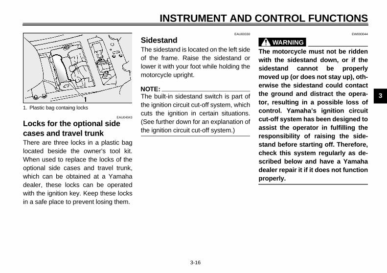
Locks for the optional side cases and travel trunk There are three locks in a plastic baglocated beside the owner’s tool kit.When used to replace the locks of theoptional side cases and travel trunk,which can be obtained at a Yamahadealer, these locks can be operatedwith the ignition key. Keep these locksin a safe place to prevent losing them.
EAU00330
Sidestand The sidestand is located on the left sideof the frame. Raise the sidestand orlower it with your foot while holding themotorcycle upright.
NOTE:_
The built-in sidestand switch is part ofthe ignition circuit cut-off system, whichcuts the ignition in certain situations.(See further down for an explanation ofthe ignition circuit cut-off system.) _
EW000044
WARNING_
The motorcycle must not be riddenwith the sidestand down, or if thesidestand cannot be properlymoved up (or does not stay up), oth-erwise the sidestand could contactthe ground and distract the opera-tor, resulting in a possible loss ofcontrol. Yamaha’s ignition circuitcut-off system has been designed toassist the operator in fulfilling theresponsibility of raising the side-stand before starting off. Therefore,check this system regularly as de-scribed below and have a Yamahadealer repair it if it does not functionproperly. _
1. Plastic bag containg locks
E_5jw.book Page 16 Friday, March 30, 2001 2:14 PM
INSTRUMENT AND CONTROL FUNCTIONS
3-17
3
EAU03741
Ignition circuit cut-off system The ignition circuit cut-off system (com-prising the sidestand switch, clutchswitch and neutral switch) has the fol-lowing functions.
● It prevents starting when the trans-mission is in gear and the side-stand is up, but the clutch lever isnot pulled.
● It prevents starting when the trans-mission is in gear and the clutchlever is pulled, but the sidestand isstill down.
● It cuts the running engine whenthe transmission is in gear and thesidestand is moved down.
Periodically check the operation of theignition circuit cut-off system accordingto the following procedure.
EW000046
WARNING_
● The vehicle must be placed onthe centerstand during this in-spection.
● If a malfunction is noted, have aYamaha dealer check the sys-tem before riding.
_
E_5jw.book Page 17 Friday, March 30, 2001 2:14 PM

INSTRUMENT AND CONTROL FUNCTIONS
3-18
3
CD-01E
With the engine turned off:1. Move the sidestand down.2. Make sure that the engine stop switch is set to “ ”.3. Turn the key to “ON”. 4. Shift the transmission into the neutral position.5. Push the start switch.Does the engine start?
The neutral switch may be defective.The motorcycle should not be ridden until checked by a Yamaha dealer.
With the engine still running:6. Move the sidestand up.7. Keep the clutch lever pulled.8. Shift the transmission into gear.9. Move the sidestand down.Does the engine stall?
After the engine has stalled:10. Move the sidestand up.11. Keep the clutch lever pulled.12. Push the start switch.Does the engine start?
The sidestand switch may be defective.The motorcycle should not be ridden until checked by a Yamaha dealer.
The clutch switch may be defective.The motorcycle should not be ridden until checked by a Yamaha dealer.
NO
NOTE:This check is most reliable if performed witha warmed-up engine.
YES
YES NO
The system is OK. The motorcycle can be ridden.
YES NO
E_5jw.book Page 18 Friday, March 30, 2001 2:14 PM

E_5jw.book Page 19 Friday, March 30, 2001 2:14 PM

PRE-OPERATION CHECKS
4
Pre-operation check list ..................................................................... 4-1
E_5jw.book Page 1 Friday, March 30, 2001 2:14 PM

4-1
4
EAU01114
4-PRE-OPERATION CHECKS
The condition of a vehicle is the owner’s responsibility. Vital components can start to deteriorate quickly and unexpectedly,even if the vehicle remains unused (for example, as a result of exposure to the elements). Any damage, fluid leakage or lossof tire air pressure could have serious consequences. Therefore, it is very important, in addition to a thorough visual inspec-tion, to check the following points before each ride.
EAU03439
Pre-operation check list CO-01E
ITEM CHECKS PAGE
Fuel• Check fuel level in fuel tank.• Refuel if necessary.• Check fuel line for leakage.
3-9
Engine oil• Check oil level in engine.• If necessary, add recommended oil to specified level.• Check vehicle for oil leakage.
6-9–6-11
Final gear oil • Check vehicle for oil leakage. 6-12
Coolant• Check coolant level in reservoir.• If necessary, add recommended coolant to specified level.• Check cooling system for leakage.
6-13–6-14
Front brake
• Check operation.• If soft or spongy, have Yamaha dealer bleed hydraulic system.• Check fluid level in reservoir.• If necessary, add recommended brake fluid to specified level.• Check hydraulic system for leakage.
6-21, 6-23–6-25
Rear brake
• Check operation.• If soft or spongy, have Yamaha dealer bleed hydraulic system.• Check fluid level in reservoir.• If necessary, add recommended brake fluid to specified level.• Check hydraulic system for leakage.
6-21–6-25
E_5jw.book Page 1 Friday, March 30, 2001 2:14 PM

PRE-OPERATION CHECKS
4-2
4
Clutch
• Check operation.• If soft or spongy, have Yamaha dealer bleed hydraulic system.• Check fluid level in reservoir.• If necessary, add recommended brake fluid to specified level.• Check hydraulic system for leakage.
6-20, 6-25
Throttle grip
• Make sure that operation is smooth.• Lubricate throttle grip, housing and cables if necessary.• Check free play.• If necessary, have Yamaha dealer make adjustment.
6-17, 6-25
Wheels and tires
• Check for damage.• Check tire condition and tread depth.• Check air pressure.• Correct if necessary.
6-17–6-20
Brake and shift pedals • Make sure that operation is smooth.• Lubricate pedal pivoting points if necessary. 6-25
Brake and clutch levers • Make sure that operation is smooth.• Lubricate lever pivoting points if necessary. 6-25
Centerstand, sidestand • Make sure that operation is smooth.• Lubricate pivots if necessary. 6-26
Chassis fasteners • Make sure that all nuts, bolts and screws are properly tightened.• Tighten if necessary. —
Instruments, lights, signals and switches
• Check operation. • Correct if necessary. —
Sidestand switch • Check operation of ignition circuit cut-off system.• If system is defective, have Yamaha dealer check vehicle. 3-16
ITEM CHECKS PAGE
E_5jw.book Page 2 Friday, March 30, 2001 2:14 PM

PRE-OPERATION CHECKS
4-3
4
NOTE:_
Pre-operation checks should be made each time the motorcycle is used. Such an inspection can be accomplished in a veryshort time; and the added safety it assures is more than worth the time involved. _
EWA00033
WARNING_
If any item in the Pre-operation check list is not working properly, have it inspected and repaired before operatingthe motorcycle. _
E_5jw.book Page 3 Friday, March 30, 2001 2:14 PM

OPERATION AND IMPORTANT RIDING POINTS
5
Starting and warming up a cold engine ............................................. 5-1Shifting .............................................................................................. 5-2Tips for reducing fuel consumption ................................................... 5-3Engine break-in ................................................................................. 5-3Parking .............................................................................................. 5-4
E_5jw.book Page 1 Friday, March 30, 2001 2:14 PM

5-1
5
EAU00372
5-OPERATION AND IMPORTANT RIDING POINTSEAU00373
WARNING_
● Become thoroughly familiarwith all operating controls andtheir functions before riding.Consult a Yamaha dealer re-garding any control or functionthat you do not thoroughly un-derstand.
● Never start the engine or oper-ate it in a closed area for anylength of time. Exhaust fumesare poisonous, and inhalingthem can cause loss of con-sciousness and death within ashort time. Always make surethat there is adequate ventila-tion.
● Before starting out, make surethat the sidestand is up. If thesidestand is not raised com-pletely, it could contact theground and distract the opera-tor, resulting in a possible lossof control.
_
EAU04096
Starting and warming up a cold engine In order for the ignition circuit cut-offsystem to enable starting, one of thefollowing conditions must be met:
● The transmission is in the neutralposition.
● The transmission is in gear withthe clutch lever pulled and thesidestand up.
EW000054
WARNING_
● Before starting the engine,check the function of the igni-tion circuit cut-off system ac-cording to the proceduredescribed on page 3-18.
● Never ride with the sidestanddown.
_
1. Turn the key to “ON” and makesure that the engine stop switch isset to “ ”.
ECA00083
CAUTION:_
The oil level warning light and en-gine trouble warning light shouldcome on for a few seconds, then gooff. If a warning light does not go off,see pages 3-2 and 3-3 for the corre-sponding warning light circuitcheck. _
2. Shift the transmission into the neu-tral position.
NOTE:_
When the transmission is in the neutralposition, the neutral indicator lightshould be on, otherwise have aYamaha dealer check the electrical cir-cuit. _
3. Start the engine by pushing thestart switch.
E_5jw.book Page 1 Friday, March 30, 2001 2:14 PM
OPERATION AND IMPORTANT RIDING POINTS
5-2
5
NOTE:_
If the engine fails to start, release thestart switch, wait a few seconds, andthen try again. Each starting attemptshould be as short as possible to pre-serve the battery. Do not crank the en-gine more than 10 seconds on any oneattempt. _
ECA00045
CAUTION:_
For maximum engine life, never ac-celerate hard when the engine iscold! _
NOTE:_
The engine is warm when it quickly re-sponds to the throttle. _
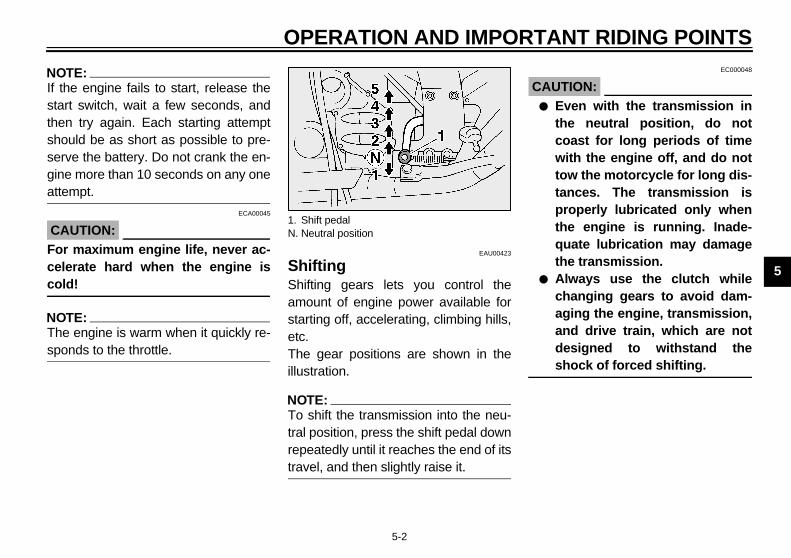
EAU00423
Shifting Shifting gears lets you control theamount of engine power available forstarting off, accelerating, climbing hills,etc.The gear positions are shown in theillustration.
NOTE:_
To shift the transmission into the neu-tral position, press the shift pedal downrepeatedly until it reaches the end of itstravel, and then slightly raise it. _
EC000048
CAUTION:_
● Even with the transmission inthe neutral position, do notcoast for long periods of timewith the engine off, and do nottow the motorcycle for long dis-tances. The transmission isproperly lubricated only whenthe engine is running. Inade-quate lubrication may damagethe transmission.
● Always use the clutch whilechanging gears to avoid dam-aging the engine, transmission,and drive train, which are notdesigned to withstand theshock of forced shifting.
_
1. Shift pedalN. Neutral position
E_5jw.book Page 2 Friday, March 30, 2001 2:14 PM
OPERATION AND IMPORTANT RIDING POINTS
5-3
5
EAU03952
Tips for reducing fuel consumption Fuel consumption depends largely onyour riding style. Consider the followingtips to reduce fuel consumption:
● Thoroughly warm up the engine.● Shift up swiftly, and avoid high en-
gine speeds during acceleration.● Do not rev the engine while shift-
ing down, and avoid high enginespeeds with no load on the engine.
● Turn the engine off instead of let-ting it idle for an extended lengthof time (e.g., in traffic jams, at traf-fic lights or at railroad crossings).
EAU01128
Engine break-in There is never a more important periodin the life of your engine than the periodbetween 0 and 1,600 km. For this rea-son, you should read the following ma-terial carefully.Since the engine is brand new, do notput an excessive load on it for the first1,600 km. The various parts in the en-gine wear and polish themselves to thecorrect operating clearances. Duringthis period, prolonged full-throttle oper-ation or any condition that might resultin engine overheating must be avoided.
EAU04032*
0–1,000 kmAvoid prolonged operation above5,000 r/min.
1,000–1,600 kmAvoid prolonged operation above6,000 r/min.
EC000056*
CAUTION:_
After 1,000 km of operation, the en-gine oil and final gear oil must bechanged, and the oil filter cartridgereplaced. _
1,600 km and beyondThe vehicle can now be operated nor-mally.
EC000053
CAUTION:_
● Keep the engine speed out ofthe tachometer red zone.
● If any engine trouble should oc-cur during the engine break-inperiod, immediately have aYamaha dealer check the vehicle.
_
E_5jw.book Page 3 Friday, March 30, 2001 2:14 PM
OPERATION AND IMPORTANT RIDING POINTS
5-4
5
EAU00461
Parking When parking, stop the engine, andthen remove the key from the mainswitch.
EW000058
WARNING_
● Since the engine and exhaustsystem can become very hot,park in a place where pedestri-ans or children are not likely totouch them.
● Do not park on a slope or onsoft ground, otherwise themotorcycle may overturn.
_
EC000062
CAUTION:_
Never park in an area where thereare fire hazards such as grass orother flammable materials. _
E_5jw.book Page 4 Friday, March 30, 2001 2:14 PM

E_5jw.book Page 5 Friday, March 30, 2001 2:14 PM
6
PERIODIC MAINTENANCE AND MINOR REPAIR
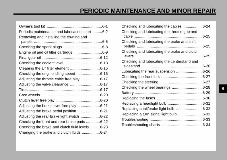
Owner’s tool kit ....................................................6-1Periodic maintenance and lubrication chart .........6-2Removing and installing the cowling and
panels ................................................................6-5Checking the spark plugs ....................................6-8Engine oil and oil filter cartridge ..........................6-9Final gear oil ......................................................6-12Checking the coolant level .................................6-13Cleaning the air filter element ............................6-15Checking the engine idling speed ......................6-16Adjusting the throttle cable free play ..................6-17Adjusting the valve clearance ............................6-17Tires ...................................................................6-17Cast wheels .......................................................6-20Clutch lever free play .........................................6-20Adjusting the brake lever free play .....................6-21Adjusting the brake pedal position .....................6-21Adjusting the rear brake light switch ..................6-22Checking the front and rear brake pads .............6-22Checking the brake and clutch fluid levels .........6-23Changing the brake and clutch fluids .................6-24
Checking and lubricating the cables ................. 6-24Checking and lubricating the throttle grip and
cable ............................................................... 6-25Checking and lubricating the brake and shift
pedals ............................................................. 6-25Checking and lubricating the brake and clutch
levers ............................................................... 6-25Checking and lubricating the centerstand and
sidestand ......................................................... 6-26Lubricating the rear suspension ........................ 6-26Checking the front fork ...................................... 6-27Checking the steering ....................................... 6-27Checking the wheel bearings ............................ 6-28Battery ............................................................... 6-29Replacing the fuses .......................................... 6-30Replacing a headlight bulb ................................ 6-31Replacing a tail/brake light bulb ........................ 6-32Replacing a turn signal light bulb ...................... 6-33Troubleshooting ................................................. 6-33Troubleshooting charts ...................................... 6-34
E_5jw.book Page 1 Friday, March 30, 2001 2:14 PM

6-1
6
EAU00462
6-PERIODIC MAINTENANCE AND MINOR REPAIR EAU00464
Safety is an obligation of the owner.Periodic inspection, adjustment and lu-brication will keep your vehicle in thesafest and most efficient condition pos-sible. The most important points of in-spection, adjustment, and lubricationare explained on the following pages.The intervals given in the periodicmaintenance and lubrication chartshould be simply considered as a gen-eral guide under normal riding condi-tions. However, DEPENDING ON THEWEATHER, TERRAIN, GEOGRAPHI-CAL LOCATION, AND INDIVIDUALUSE, THE MAINTENANCE INTER-VALS MAY NEED TO BE SHORT-ENED.
EW000060
WARNING_
If you are not familiar with motor-cycle maintenance work, have aYamaha dealer do it for you. _
EAU03711
Owner’s tool kit The owner’s tool kit is located underthe rider seat. (See page 3-10 for riderseat removal and installation proce-dures.)The service information included in thismanual and the tools provided in theowner’s tool kit are intended to assistyou in the performance of preventivemaintenance and minor repairs. How-ever, additional tools such as a torquewrench may be necessary to performcertain maintenance work correctly.
NOTE:_
If you do not have the tools or experi-ence required for a particular job, havea Yamaha dealer perform it for you. _
EW000063
WARNING_
Modifications not approved byYamaha may cause loss of perfor-mance and render the vehicle un-safe for use. Consult a Yamahadealer before attempting any chang-es. _
1. Owner’s tool kit
E_5jw.book Page 1 Friday, March 30, 2001 2:14 PM

PERIODIC MAINTENANCE AND MINOR REPAIR
6-2
6
EAU03685
Periodic maintenance and lubrication chart
NOTE:_
● The annual checks must be performed every year, except if a kilometer-based maintenance is performed instead. ● From 50,000 km, repeat the maintenance intervals starting from 10,000 km. ● Items marked with an asterisk should be performed by a Yamaha dealer as they require special tools, data and techni-
cal skills. _
CP-03E
NO. ITEM CHECK OR MAINTENANCE JOBODOMETER READING (× 1,000 km) ANNUAL
CHECK1 10 20 30 40
1 * Fuel line • Check fuel hoses for cracks or damage. √ √ √ √ √
2 Spark plugs• Check condition.• Clean and regap. √ √
• Replace. √ √
3 * Valves • Check valve clearance.• Adjust. Every 40,000 km
4 Air filter element• Clean. √ √• Replace. √ √
5 * Clutch • Check operation, fluid level and vehicle for fluid leakage. (See NOTE on page 6-4.) √ √ √ √ √
6 * Front brake• Check operation, fluid level and vehicle for fluid leakage.
(See NOTE on page 6-4.) √ √ √ √ √ √
• Replace brake pads. Whenever worn to the limit
7 * Rear brake• Check operation, fluid level and vehicle for fluid leakage.
(See NOTE on page 6-4.) √ √ √ √ √ √
• Replace brake pads. Whenever worn to the limit
E_5jw.book Page 2 Friday, March 30, 2001 2:14 PM
PERIODIC MAINTENANCE AND MINOR REPAIR
6-3
6
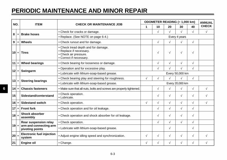
8 * Brake hoses• Check for cracks or damage. √ √ √ √ √
• Replace. (See NOTE on page 6-4.) Every 4 years
9 * Wheels • Check runout and for damage. √ √ √ √
10 * Tires
• Check tread depth and for damage.• Replace if necessary.• Check air pressure.• Correct if necessary.
√ √ √ √
11 * Wheel bearings • Check bearing for looseness or damage. √ √ √ √
12 * Swingarm• Operation and for excessive play. √ √ √ √
• Lubricate with lithium-soap-based grease. Every 50,000 km
13 * Steering bearings• Check bearing play and steering for roughness. √ √ √ √ √
• Lubricate with lithium-soap-based grease. Every 20,000 km
14 * Chassis fasteners • Make sure that all nuts, bolts and screws are properly tightened. √ √ √ √ √
15 Sidestand/centerstand • Check operation.• Lubricate. √ √ √ √ √
16 * Sidestand switch • Check operation. √ √ √ √ √ √
17 * Front fork • Check operation and for oil leakage. √ √ √ √
18 *Shock absorber assembly • Check operation and shock absorber for oil leakage. √ √ √ √
19 *Rear suspension relay arm and connecting arm pivoting points
• Check operation. √ √ √ √
• Lubricate with lithium-soap-based grease. √ √
20 *Electronic fuel injection system • Adjust engine idling speed and synchronization. √ √ √ √ √ √
21 Engine oil • Change. √ √ √ √ √ √
NO. ITEM CHECK OR MAINTENANCE JOBODOMETER READING (× 1,000 km) ANNUAL
CHECK1 10 20 30 40
E_5jw.book Page 3 Friday, March 30, 2001 2:14 PM
PERIODIC MAINTENANCE AND MINOR REPAIR
6-4
6EAU03892
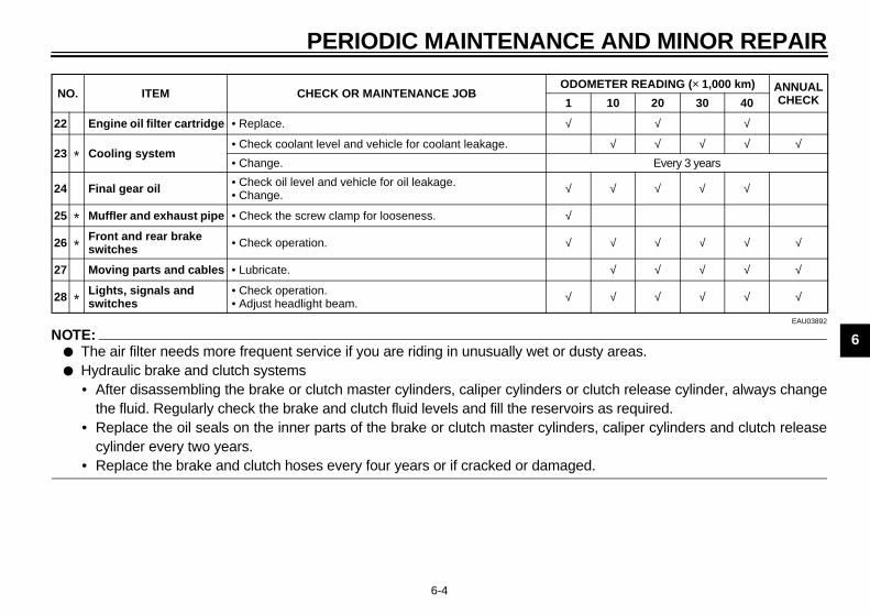
NOTE:_
● The air filter needs more frequent service if you are riding in unusually wet or dusty areas.● Hydraulic brake and clutch systems
• After disassembling the brake or clutch master cylinders, caliper cylinders or clutch release cylinder, always changethe fluid. Regularly check the brake and clutch fluid levels and fill the reservoirs as required.
• Replace the oil seals on the inner parts of the brake or clutch master cylinders, caliper cylinders and clutch releasecylinder every two years.
• Replace the brake and clutch hoses every four years or if cracked or damaged. _
22 Engine oil filter cartridge • Replace. √ √ √
23 * Cooling system• Check coolant level and vehicle for coolant leakage. √ √ √ √ √
• Change. Every 3 years
24 Final gear oil • Check oil level and vehicle for oil leakage.• Change. √ √ √ √ √
25 * Muffler and exhaust pipe • Check the screw clamp for looseness. √
26 *Front and rear brake switches • Check operation. √ √ √ √ √ √
27 Moving parts and cables • Lubricate. √ √ √ √ √
28 *Lights, signals and switches
• Check operation.• Adjust headlight beam. √ √ √ √ √ √
NO. ITEM CHECK OR MAINTENANCE JOBODOMETER READING (× 1,000 km) ANNUAL
CHECK1 10 20 30 40
E_5jw.book Page 4 Friday, March 30, 2001 2:14 PM

PERIODIC MAINTENANCE AND MINOR REPAIR
6-5
6
EAU03516
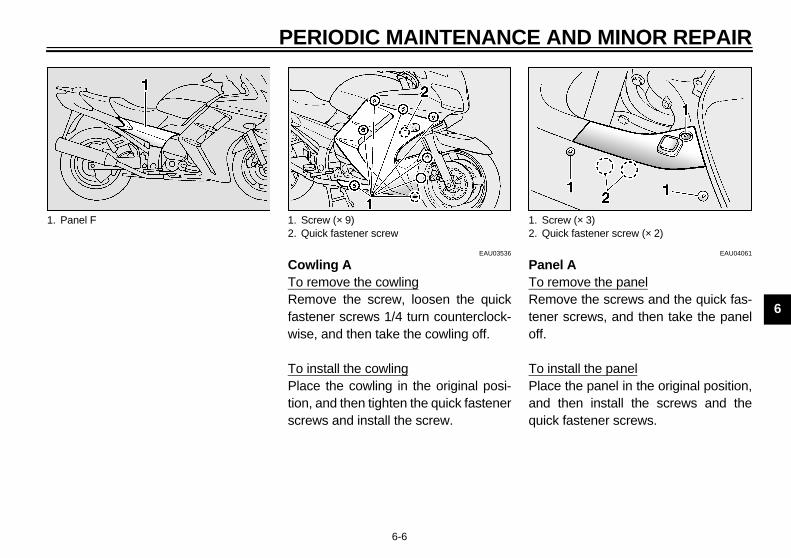
Removing and installing the cowling and panels The cowling and panels shown aboveneed to be removed to perform someof the maintenance jobs described inthis chapter. Refer to this section eachtime the cowling or a panel needs to beremoved and installed.
1. Cowling A 1. Panel A2. Panel B3. Panel C4. Panel D
1. Panel E
E_5jw.book Page 5 Friday, March 30, 2001 2:14 PM
PERIODIC MAINTENANCE AND MINOR REPAIR
6-6
6
EAU03536
Cowling ATo remove the cowlingRemove the screw, loosen the quickfastener screws 1/4 turn counterclock-wise, and then take the cowling off.
To install the cowlingPlace the cowling in the original posi-tion, and then tighten the quick fastenerscrews and install the screw.
EAU04061
Panel ATo remove the panelRemove the screws and the quick fas-tener screws, and then take the paneloff.
To install the panelPlace the panel in the original position,and then install the screws and thequick fastener screws.
1. Panel F 1. Screw (× 9)2. Quick fastener screw
1. Screw (× 3)2. Quick fastener screw (× 2)
E_5jw.book Page 6 Friday, March 30, 2001 2:14 PM
PERIODIC MAINTENANCE AND MINOR REPAIR
6-7
6
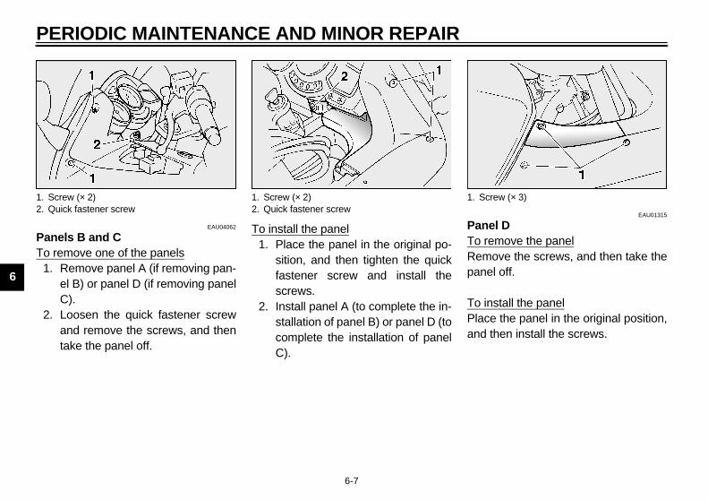
EAU04062
Panels B and CTo remove one of the panels
1. Remove panel A (if removing pan-el B) or panel D (if removing panelC).
2. Loosen the quick fastener screwand remove the screws, and thentake the panel off.
To install the panel1. Place the panel in the original po-
sition, and then tighten the quickfastener screw and install thescrews.
2. Install panel A (to complete the in-stallation of panel B) or panel D (tocomplete the installation of panelC).
EAU01315
Panel DTo remove the panelRemove the screws, and then take thepanel off.
To install the panelPlace the panel in the original position,and then install the screws.
1. Screw (× 2)2. Quick fastener screw
1. Screw (× 2)2. Quick fastener screw
1. Screw (× 3)
E_5jw.book Page 7 Friday, March 30, 2001 2:14 PM
PERIODIC MAINTENANCE AND MINOR REPAIR
6-8
6
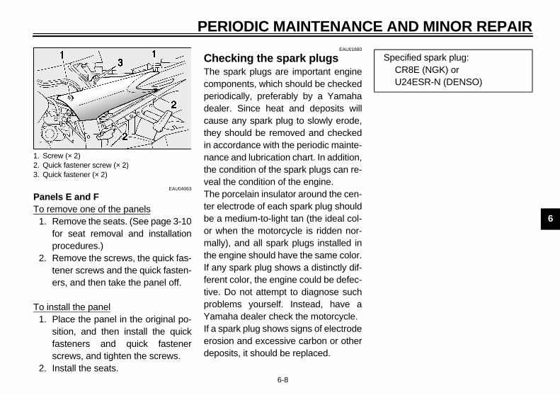
EAU04063
Panels E and FTo remove one of the panels
1. Remove the seats. (See page 3-10for seat removal and installationprocedures.)
2. Remove the screws, the quick fas-tener screws and the quick fasten-ers, and then take the panel off.
To install the panel1. Place the panel in the original po-
sition, and then install the quickfasteners and quick fastenerscrews, and tighten the screws.
2. Install the seats.
EAU01880
Checking the spark plugs The spark plugs are important enginecomponents, which should be checkedperiodically, preferably by a Yamahadealer. Since heat and deposits willcause any spark plug to slowly erode,they should be removed and checkedin accordance with the periodic mainte-nance and lubrication chart. In addition,the condition of the spark plugs can re-veal the condition of the engine.The porcelain insulator around the cen-ter electrode of each spark plug shouldbe a medium-to-light tan (the ideal col-or when the motorcycle is ridden nor-mally), and all spark plugs installed inthe engine should have the same color.If any spark plug shows a distinctly dif-ferent color, the engine could be defec-tive. Do not attempt to diagnose suchproblems yourself. Instead, have aYamaha dealer check the motorcycle.If a spark plug shows signs of electrodeerosion and excessive carbon or otherdeposits, it should be replaced.
1. Screw (× 2)2. Quick fastener screw (× 2)3. Quick fastener (× 2)
Specified spark plug:CR8E (NGK) orU24ESR-N (DENSO)
E_5jw.book Page 8 Friday, March 30, 2001 2:14 PM
PERIODIC MAINTENANCE AND MINOR REPAIR
6-9
6
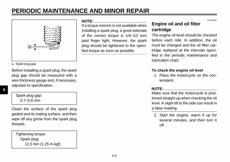
Before installing a spark plug, the sparkplug gap should be measured with awire thickness gauge and, if necessary,adjusted to specification.
Clean the surface of the spark pluggasket and its mating surface, and thenwipe off any grime from the spark plugthreads.
NOTE:_
If a torque wrench is not available wheninstalling a spark plug, a good estimateof the correct torque is 1/4–1/2 turnpast finger tight. However, the sparkplug should be tightened to the speci-fied torque as soon as possible. _
EAU03997
Engine oil and oil filter cartridge The engine oil level should be checkedbefore each ride. In addition, the oilmust be changed and the oil filter car-tridge replaced at the intervals speci-fied in the periodic maintenance andlubrication chart.
To check the engine oil level1. Place the motorcycle on the cen-
terstand.
NOTE:_
Make sure that the motorcycle is posi-tioned straight up when checking the oillevel. A slight tilt to the side can result ina false reading. _
2. Start the engine, warm it up forseveral minutes, and then turn itoff.
a. Spark plug gap
Spark plug gap:0.7–0.8 mm
Tightening torque:Spark plug:
12.5 Nm (1.25 m·kgf)
E_5jw.book Page 9 Friday, March 30, 2001 2:14 PM
PERIODIC MAINTENANCE AND MINOR REPAIR
6-10
6
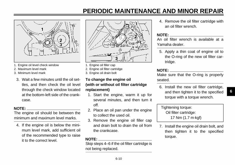
3. Wait a few minutes until the oil set-tles, and then check the oil levelthrough the check window locatedat the bottom-left side of the crank-case.
NOTE:_
The engine oil should be between theminimum and maximum level marks. _
4. If the engine oil is below the mini-mum level mark, add sufficient oilof the recommended type to raiseit to the correct level.
To change the engine oil (with or without oil filter cartridge replacement)
1. Start the engine, warm it up forseveral minutes, and then turn itoff.
2. Place an oil pan under the engineto collect the used oil.
3. Remove the engine oil filler capand drain bolt to drain the oil fromthe crankcase.
NOTE:_
Skip steps 4–6 if the oil filter cartridge isnot being replaced. _
4. Remove the oil filter cartridge withan oil filter wrench.
NOTE:_
An oil filter wrench is available at aYamaha dealer. _
5. Apply a thin coat of engine oil tothe O-ring of the new oil filter car-tridge.
NOTE:_
Make sure that the O-ring is properlyseated. _
6. Install the new oil filter cartridge,and then tighten it to the specifiedtorque with a torque wrench.
7. Install the engine oil drain bolt, andthen tighten it to the specifiedtorque.
1. Engine oil level check window2. Maximum level mark3. Minimum level mark
1. Engine oil filler cap2. Engine oil filter cartridge3. Engine oil drain bolt
Tightening torque:Oil filter cartridge:
17 Nm (1.7 m·kgf)
E_5jw.book Page 10 Friday, March 30, 2001 2:14 PM
PERIODIC MAINTENANCE AND MINOR REPAIR
6-11
6
8. Add the specified amount of therecommended engine oil, andthen install and tighten the oil fillercap.
EC000072
CAUTION:_
● In order to prevent clutch slip-page (since the engine oil alsolubricates the clutch), do notmix any chemical additives withthe oil or use oils of a highergrade than “CD”. In addition, donot use oils labeled “ENERGYCONSERVING II” or higher.
● Make sure that no foreign mate-rial enters the crankcase.
_
9. Start the engine, and then let it idlefor several minutes while checkingit for oil leakage. If oil is leaking,immediately turn the engine offand check for the cause.
NOTE:_
After the engine is started, the engineoil level warning light should go off if theoil level is sufficient. _
EC000067
CAUTION:_
If the oil level warning light flickersor remains on, immediately turn theengine off and have a Yamaha deal-er check the vehicle. _
10. Turn the engine off, and thencheck the oil level and correct it ifnecessary.
Tightening torque:Engine oil drain bolt:
43 Nm (4.3 m·kgf)
Recommended engine oil:See page 8-1.
Oil quantity:Without oil filter cartridge replacement:
3.8 LWith oil filter cartridge replacement:
4 LTotal amount (dry engine):
4.9 L
E_5jw.book Page 11 Friday, March 30, 2001 2:14 PM
PERIODIC MAINTENANCE AND MINOR REPAIR
6-12
6
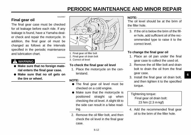
EAU04067
Final gear oil The final gear case must be checkedfor oil leakage before each ride. If anyleakage is found, have a Yamaha deal-er check and repair the motorcycle. Inaddition, the final gear oil must bechanged as follows at the intervalsspecified in the periodic maintenanceand lubrication chart.
EW000066
WARNING_
● Make sure that no foreign mate-rial enters the final gear case.
● Make sure that no oil gets onthe tire or wheel.
_
To check the final gear oil level1. Place the motorcycle on the cen-
terstand.
NOTE:_
● The final gear oil level must bechecked on a cold engine.
● Make sure that the motorcycle ispositioned straight up whenchecking the oil level. A slight tilt tothe side can result in a false read-ing.
_
2. Remove the oil filler bolt, and thencheck the oil level in the final gearcase.
NOTE:_
The oil level should be at the brim ofthe filler hole. _
3. If the oil is below the brim of the fill-er hole, add sufficient oil of the rec-ommended type to raise it to thecorrect level.
To change the final gear oil1. Place an oil pan under the final
gear case to collect the used oil.2. Remove the oil filler bolt and drain
bolt to drain the oil from the finalgear case.
3. Install the final gear oil drain bolt,and then tighten it to the specifiedtorque.
4. Add the recommended final gearoil to the brim of the filler hole.
1. Final gear oil filler bolt2. Final gear oil drain bolt3. Correct oil level
Tightening torque:Final gear oil drain bolt:
23 Nm (2.3 m·kgf)
E_5jw.book Page 12 Friday, March 30, 2001 2:14 PM
PERIODIC MAINTENANCE AND MINOR REPAIR
6-13
6
5. Install and tighten the filler bolt.6. Check the final gear case for oil
leakage. If oil is leaking, check forthe cause.
EAU04044
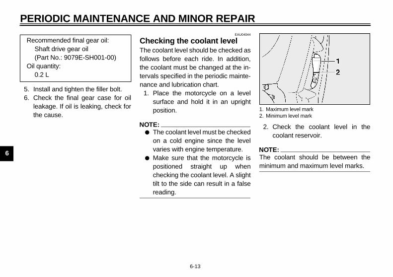
Checking the coolant level The coolant level should be checked asfollows before each ride. In addition,the coolant must be changed at the in-tervals specified in the periodic mainte-nance and lubrication chart.
1. Place the motorcycle on a levelsurface and hold it in an uprightposition.
NOTE:_
● The coolant level must be checkedon a cold engine since the levelvaries with engine temperature.
● Make sure that the motorcycle ispositioned straight up whenchecking the coolant level. A slighttilt to the side can result in a falsereading.
_
2. Check the coolant level in thecoolant reservoir.
NOTE:_
The coolant should be between theminimum and maximum level marks. _
Recommended final gear oil:Shaft drive gear oil (Part No.: 9079E-SH001-00)
Oil quantity:0.2 L
1. Maximum level mark2. Minimum level mark
E_5jw.book Page 13 Friday, March 30, 2001 2:14 PM

PERIODIC MAINTENANCE AND MINOR REPAIR
6-14
6
3. If the coolant is at or below theminimum level mark, removecowling A (See page 6-6 for cowl-ing removal and installation proce-dures.), open the reservoir cap,add coolant to the maximum levelmark, close the reservoir cap, andthen install the cowling.
EC000080
CAUTION:_
● If coolant is not available, usedistilled water or soft tap waterinstead. Do not use hard wateror salt water since it is harmfulto the engine.
● If water has been used insteadof coolant, replace it with cool-ant as soon as possible, other-wise the engine may not besufficiently cooled and the cool-ing system will not be protectedagainst frost and corrosion.
● If water has been added to thecoolant, have a Yamaha dealercheck the antifreeze content ofthe coolant as soon as possible,otherwise the effectiveness ofthe coolant will be reduced.
_
EW000067
WARNING_
Never attempt to remove the radia-tor cap when the engine is hot. _
NOTE:_
● The radiator fan is automaticallyswitched on or off according to thecoolant temperature in the radia-tor.
● If the engine overheats, see page6-35 for further instructions.
_
1. Screw2. Reservoir cap cover3. Reservoir cap
Coolant reservoir capacity:0.25 L
E_5jw.book Page 14 Friday, March 30, 2001 2:14 PM

PERIODIC MAINTENANCE AND MINOR REPAIR
6-15
6
EAU03998*
Cleaning the air filter element The air filter element should be cleanedat the intervals specified in the periodicmaintenance and lubrication chart.Clean the air filter element more fre-quently if you are riding in unusuallywet or dusty areas.
1. Remove panel E. (See page 6-8for panel removal and installationprocedures.)
2. Remove the intake air shroud byremoving the quick fasteners.
3. Remove the air filter case cover byremoving the screws.
4. Pull the air filter element out.
1. Air shroud2. Quick fastener (× 4)
1. Air filter case cover2. Screw (× 4)
1. Air filter element
E_5jw.book Page 15 Friday, March 30, 2001 2:14 PM
PERIODIC MAINTENANCE AND MINOR REPAIR
6-16
6
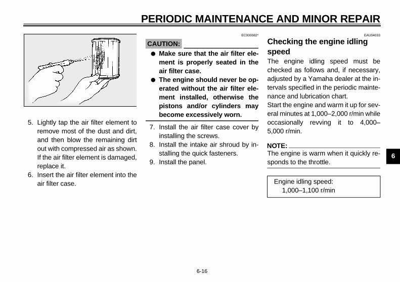
5. Lightly tap the air filter element toremove most of the dust and dirt,and then blow the remaining dirtout with compressed air as shown.If the air filter element is damaged,replace it.
6. Insert the air filter element into theair filter case.
EC000082*
CAUTION:_
● Make sure that the air filter ele-ment is properly seated in theair filter case.
● The engine should never be op-erated without the air filter ele-ment installed, otherwise thepistons and/or cylinders maybecome excessively worn.
_
7. Install the air filter case cover byinstalling the screws.
8. Install the intake air shroud by in-stalling the quick fasteners.
9. Install the panel.
EAU04033
Checking the engine idling speed The engine idling speed must bechecked as follows and, if necessary,adjusted by a Yamaha dealer at the in-tervals specified in the periodic mainte-nance and lubrication chart.Start the engine and warm it up for sev-eral minutes at 1,000–2,000 r/min whileoccasionally revving it to 4,000–5,000 r/min.
NOTE:_
The engine is warm when it quickly re-sponds to the throttle. _
Engine idling speed:1,000–1,100 r/min
E_5jw.book Page 16 Friday, March 30, 2001 2:14 PM

PERIODIC MAINTENANCE AND MINOR REPAIR
6-17
6
EAU00635
Adjusting the throttle cable free play The throttle cable free play shouldmeasure 3–5 mm at the throttle grip.Periodically check the throttle cablefree play and, if necessary, have aYamaha dealer adjust it.
EAU00637
Adjusting the valve clearance The valve clearance changes with use,resulting in improper air-fuel mixtureand/or engine noise. To prevent thisfrom occurring, the valve clearancemust be adjusted by a Yamaha dealerat the intervals specified in the periodicmaintenance and lubrication chart.
EAU03296
Tires To maximize the performance, durabil-ity, and safe operation of your motor-cycle, note the following pointsregarding the specified tires.
Tire air pressureThe tire air pressure should bechecked and, if necessary, adjustedbefore each ride.
EW000082
WARNING_
● The tire air pressure must bechecked and adjusted on coldtires (i.e., when the temperatureof the tires equals the ambienttemperature).
● The tire air pressure must beadjusted in accordance with theriding speed and with the totalweight of rider, passenger, car-go, and accessories approvedfor this model.
_
a. Throttle cable free play
E_5jw.book Page 17 Friday, March 30, 2001 2:14 PM

PERIODIC MAINTENANCE AND MINOR REPAIR
6-18
6
CE-01E
CE-07E
EW000083
WARNING_
Proper loading of your motorcycleis important for several characteris-tics of your motorcycle, such ashandling, braking, performance andsafety. Do not carry loosely packeditems that can shift. Securely packyour heaviest items close to thecenter of the motorcycle, and dis-tribute the weight evenly from sideto side. Properly adjust the suspen-sion for your load, and check thecondition and pressure of your tires.NEVER OVERLOAD YOUR MOTOR-CYCLE. Make sure that the totalweight of the cargo, rider, passen-ger, and accessories (cowling, sad-dlebags, etc. if approved for thismodel) does not exceed the maxi-mum load of the motorcycle. Opera-tion of an overloaded motorcyclecould cause tire damage, an acci-dent, or even injury. _
Tire inspectionAlways check the tires before operatingthe motorcycle. If a tire tread showscrosswise lines (minimum tread depth),if the tire has a nail or glass fragmentsin it, or if the sidewall is cracked, con-tact a Yamaha dealer immediately andhave the tire replaced.
Tire air pressure(measured on cold tires)
Load* Front Rear
Up to 90 kg250 kPa(2.50 kgf/cm2,2.50 bar)
250 kPa(2.50 kgf/cm2,2.50 bar)
90 kg–maximum250 kPa(2.50 kgf/cm2,2.50 bar)
290 kPa(2.90 kgf/cm2,2.90 bar)
High-speed riding250 kPa(2.50 kgf/cm2,2.50 bar)
290 kPa(2.90 kgf/cm2,2.90 bar)
Maximum load* 208 kg
* Total weight of rider, passenger, cargo and accessories
1. Tire sidewall2. Tire wear indicatora. Tire tread depth
E_5jw.book Page 18 Friday, March 30, 2001 2:14 PM
PERIODIC MAINTENANCE AND MINOR REPAIR
6-19
6
EW000079
WARNING_
● Have a Yamaha dealer replaceexcessively worn tires. Besidesbeing illegal, operating themotorcycle with excessivelyworn tires decreases riding sta-bility and can lead to loss ofcontrol.
● The replacement of all wheel-and brake-related parts, includ-ing the tires, should be left to aYamaha dealer, who has thenecessary professional knowl-edge and experience.
_
CE-20E
NOTE:_
The tire tread depth limits may differfrom country to country. Always complywith the local regulations. _
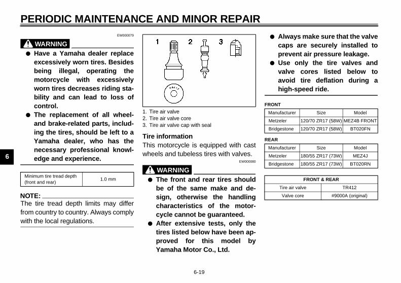
Tire informationThis motorcycle is equipped with castwheels and tubeless tires with valves.
EW000080
WARNING_
● The front and rear tires shouldbe of the same make and de-sign, otherwise the handlingcharacteristics of the motor-cycle cannot be guaranteed.
● After extensive tests, only thetires listed below have been ap-proved for this model byYamaha Motor Co., Ltd.
● Always make sure that the valvecaps are securely installed toprevent air pressure leakage.
● Use only the tire valves andvalve cores listed below toavoid tire deflation during ahigh-speed ride.
_
CE-10E
CE-14EMinimum tire tread depth (front and rear)
1.0 mm
1. Tire air valve2. Tire air valve core3. Tire air valve cap with seal
FRONT
Manufacturer Size Model
Metzeler 120/70 ZR17 (58W) MEZ4B FRONT
Bridgestone 120/70 ZR17 (58W) BT020FN
REAR
Manufacturer Size Model
Metzeler 180/55 ZR17 (73W) MEZ4J
Bridgestone 180/55 ZR17 (73W) BT020RN
FRONT & REAR
Tire air valve TR412
Valve core #9000A (original)
E_5jw.book Page 19 Friday, March 30, 2001 2:14 PM

PERIODIC MAINTENANCE AND MINOR REPAIR
6-20
6
EAU00684
WARNING_
This motorcycle is fitted with super-high-speed tires. Note the followingpoints in order to make the most ef-ficient use of these tires.
● Use only the specified replace-ment tires. Other tires may runthe danger of bursting at superhigh speeds.
● Brand-new tires can have a rela-tively poor grip on certain roadsurfaces until they have been“broken in”. Therefore, it is ad-visable before doing any high-speed riding to ride conserva-tively for approximately 100 kmafter installing a new tire.
● The tires must be warmed upbefore a high-speed run.
● Always adjust the tire air pres-sure according to the operatingconditions.
_
EAU03773
Cast wheels To maximize the performance, durabil-ity, and safe operation of your motor-cycle, note the following pointsregarding the specified wheels.
● The wheel rims should be checkedfor cracks, bends or warpage be-fore each ride. If any damage isfound, have a Yamaha dealer re-place the wheel. Do not attempteven the smallest repair to thewheel. A deformed or crackedwheel must be replaced.
● The wheel should be balancedwhenever either the tire or wheelhas been changed or replaced. Anunbalanced wheel can result inpoor performance, adverse han-dling characteristics, and a short-ened tire life.
● Ride at moderate speeds afterchanging a tire since the tire sur-face must first be “broken in” for itto develop its optimal characteris-tics.
EAU00695
Clutch lever free play Since this model is equipped with a hy-draulic clutch, adjusting the clutch leverfree play is not needed. However, it isnecessary to check the clutch fluid leveland check the hydraulic system for leak-age before each ride. If the clutch leverfree play does become excessive, andshifting becomes rough or clutch slip-page occurs, causing poor acceleration,there may be air in the clutch system. Ifthere is air in the hydraulic system, havea Yamaha dealer bleed the system be-fore operating the motorcycle.
E_5jw.book Page 20 Friday, March 30, 2001 2:14 PM

PERIODIC MAINTENANCE AND MINOR REPAIR
6-21
6
EAU00697
Adjusting the brake lever free play The brake lever free play should mea-sure 3–11 mm as shown. Periodicallycheck the brake lever free play and, ifnecessary, have a Yamaha dealer ad-just it.
EW000100
WARNING_
An incorrect brake lever free play in-dicates a hazardous condition in thebrake system. Do not operate themotorcycle until the brake systemhas been checked or repaired by aYamaha dealer. _
EAU00712
Adjusting the brake pedal position The top of the brake pedal should bepositioned approximately 40 mm belowthe top of the footrest as shown. Peri-odically check the brake pedal positionand, if necessary, have a Yamahadealer adjust it.
EW000109
WARNING_
A soft or spongy feeling in the brakepedal can indicate the presence ofair in the hydraulic system. If thereis air in the hydraulic system, have aYamaha dealer bleed the system be-fore operating the motorcycle. Air inthe hydraulic system will diminishthe braking performance, whichmay result in loss of control and anaccident. _
a. Brake lever free play a. Distance between brake pedal and footrest
E_5jw.book Page 21 Friday, March 30, 2001 2:14 PM

PERIODIC MAINTENANCE AND MINOR REPAIR
6-22
6
EAU00713
Adjusting the rear brake light switch The rear brake light switch, which is ac-tivated by the brake pedal, is properlyadjusted when the brake light comeson just before braking takes effect. Ifnecessary, adjust the brake light switchas follows.Turn the adjusting nut while holding therear brake light switch in place. Tomake the brake light come on earlier,turn the adjusting nut in direction a. Tomake the brake light come on later,turn the adjusting nut in direction b.
EAU00721
Checking the front and rear brake pads The front and rear brake pads must bechecked for wear at the intervals spec-ified in the periodic maintenance andlubrication chart.
EAU00725
Front brake padsEach front brake pad is provided with awear indicator groove, which allowsyou to check the brake pad wear with-out having to disassemble the brake.To check the brake pad wear, checkthe wear indicator groove. If a brakepad has worn to the point that the wearindicator groove has almost disap-peared, have a Yamaha dealer replacethe brake pads as a set.
1. Rear brake light switch2. Rear brake light switch adjusting nut
1. Brake pad wear indicator groove (× 2)
E_5jw.book Page 22 Friday, March 30, 2001 2:14 PM
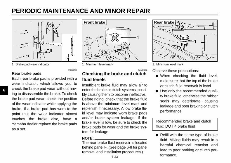
PERIODIC MAINTENANCE AND MINOR REPAIR
6-23
6
EAU00728
Rear brake padsEach rear brake pad is provided with awear indicator, which allows you tocheck the brake pad wear without hav-ing to disassemble the brake. To checkthe brake pad wear, check the positionof the wear indicator while applying thebrake. If a brake pad has worn to thepoint that the wear indicator almosttouches the brake disc, have aYamaha dealer replace the brake padsas a set.
EAU04098
Checking the brake and clutch fluid levels Insufficient brake fluid may allow air toenter the brake or clutch systems, possi-bly causing them to become ineffective.Before riding, check that the brake fluidis above the minimum level mark andreplenish if necessary. A low brake flu-id level may indicate worn brake padsand/or brake system leakage. If thebrake level is low, be sure to check thebrake pads for wear and the brake sys-tem for leakage.
NOTE:_
The rear brake fluid reservoir is locatedbehind panel F. (See page 6-8 for panelremoval and installation procedures.) _
Observe these precautions:● When checking the fluid level,
make sure that the top of the brakeor clutch fluid reservoir is level.
● Use only the recommended quali-ty brake fluid, otherwise the rubberseals may deteriorate, causingleakage and poor braking or clutchperformance.
● Refill with the same type of brakefluid. Mixing fluids may result in aharmful chemical reaction andlead to poor braking or clutch per-formance.
1. Brake pad wear indicator 1. Minimum level mark
Front brake
1. Minimum level mark
Recommended brake and clutch fluid: DOT 4 brake fluid
Rear brake
E_5jw.book Page 23 Friday, March 30, 2001 2:14 PM
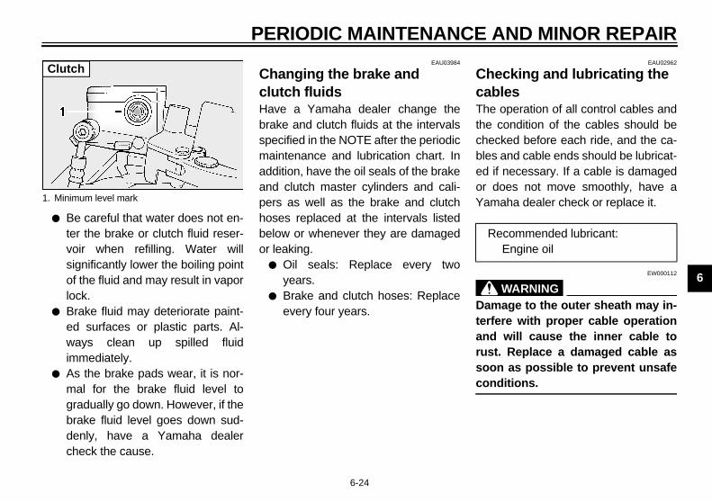
PERIODIC MAINTENANCE AND MINOR REPAIR
6-24
6
● Be careful that water does not en-ter the brake or clutch fluid reser-voir when refilling. Water willsignificantly lower the boiling pointof the fluid and may result in vaporlock.
● Brake fluid may deteriorate paint-ed surfaces or plastic parts. Al-ways clean up spilled fluidimmediately.
● As the brake pads wear, it is nor-mal for the brake fluid level togradually go down. However, if thebrake fluid level goes down sud-denly, have a Yamaha dealercheck the cause.
EAU03984
Changing the brake and clutch fluids Have a Yamaha dealer change thebrake and clutch fluids at the intervalsspecified in the NOTE after the periodicmaintenance and lubrication chart. Inaddition, have the oil seals of the brakeand clutch master cylinders and cali-pers as well as the brake and clutchhoses replaced at the intervals listedbelow or whenever they are damagedor leaking.
● Oil seals: Replace every twoyears.
● Brake and clutch hoses: Replaceevery four years.
EAU02962
Checking and lubricating the cables The operation of all control cables andthe condition of the cables should bechecked before each ride, and the ca-bles and cable ends should be lubricat-ed if necessary. If a cable is damagedor does not move smoothly, have aYamaha dealer check or replace it.
EW000112
WARNING_
Damage to the outer sheath may in-terfere with proper cable operationand will cause the inner cable torust. Replace a damaged cable assoon as possible to prevent unsafeconditions. _
1. Minimum level mark
Clutch
Recommended lubricant:Engine oil
E_5jw.book Page 24 Friday, March 30, 2001 2:14 PM
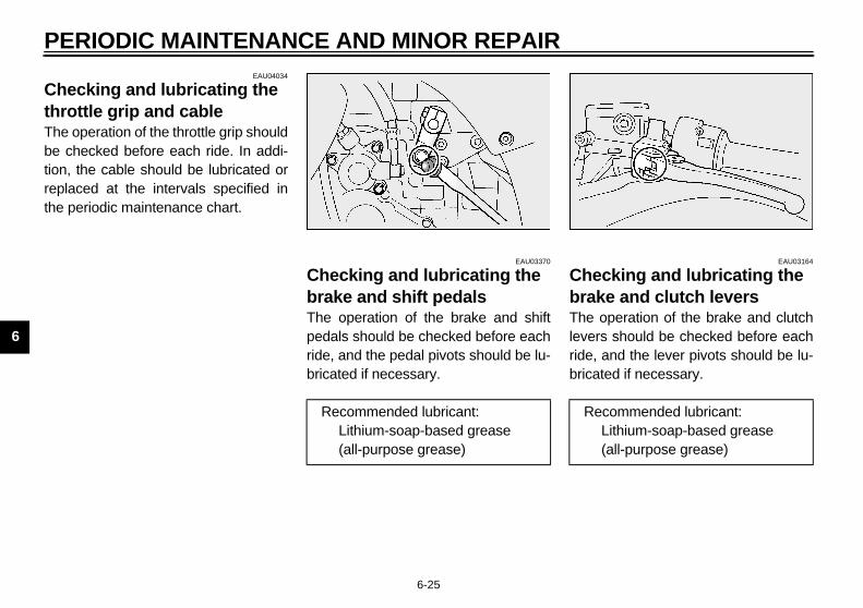
PERIODIC MAINTENANCE AND MINOR REPAIR
6-25
6
EAU04034
Checking and lubricating the throttle grip and cable The operation of the throttle grip shouldbe checked before each ride. In addi-tion, the cable should be lubricated orreplaced at the intervals specified inthe periodic maintenance chart.
EAU03370
Checking and lubricating the brake and shift pedals The operation of the brake and shiftpedals should be checked before eachride, and the pedal pivots should be lu-bricated if necessary.
EAU03164
Checking and lubricating the brake and clutch levers The operation of the brake and clutchlevers should be checked before eachride, and the lever pivots should be lu-bricated if necessary.
Recommended lubricant:Lithium-soap-based grease (all-purpose grease)
Recommended lubricant:Lithium-soap-based grease (all-purpose grease)
E_5jw.book Page 25 Friday, March 30, 2001 2:14 PM

PERIODIC MAINTENANCE AND MINOR REPAIR
6-26
6
EAU03371
Checking and lubricating the centerstand and sidestand The operation of the centerstand andsidestand should be checked beforeeach ride, and the pivots and metal-to-metal contact surfaces should be lubri-cated if necessary.
EW000114
WARNING_
If the centerstand or sidestand doesnot move up and down smoothly,have a Yamaha dealer check or re-pair it. _
EAU03166
Lubricating the rear suspension The pivoting points of the rear suspen-sion must be lubricated at the intervalsspecified in the periodic maintenanceand lubrication chart.
Recommended lubricant:Lithium-soap-based grease (all-purpose grease)
Recommended lubricant:Lithium-soap-based grease (all-purpose grease)
E_5jw.book Page 26 Friday, March 30, 2001 2:14 PM

PERIODIC MAINTENANCE AND MINOR REPAIR
6-27
6
EAU02939
Checking the front fork The condition and operation of the frontfork must be checked as follows at theintervals specified in the periodic main-tenance and lubrication chart.
To check the conditionEW000115
WARNING_
Securely support the motorcycle sothat there is no danger of it fallingover. _
Check the inner tubes for scratches,damage and excessive oil leakage.
To check the operation1. Place the motorcycle on a level
surface and hold it in an uprightposition.
2. While applying the front brake,push down hard on the handle-bars several times to check if thefront fork compresses and re-bounds smoothly.
EC000098
CAUTION:_
If any damage is found or the frontfork does not operate smoothly,have a Yamaha dealer check or re-pair it. _
EAU00794
Checking the steering Worn or loose steering bearings maycause danger. Therefore, the operationof the steering must be checked as fol-lows at the intervals specified in the pe-riodic maintenance and lubricationchart.
1. Place a stand under the engine toraise the front wheel off theground.
EW000115
WARNING_
Securely support the motorcycle sothat there is no danger of it fallingover. _
E_5jw.book Page 27 Friday, March 30, 2001 2:14 PM

PERIODIC MAINTENANCE AND MINOR REPAIR
6-28
6
2. Hold the lower ends of the frontfork legs and try to move them for-ward and backward. If any freeplay can be felt, have a Yamahadealer check or repair the steer-ing.
EAU01144
Checking the wheel bearings The front and rear wheel bearings mustbe checked at the intervals specified inthe periodic maintenance and lubrica-tion chart. If there is play in the wheelhub or if the wheel does not turnsmoothly, have a Yamaha dealercheck the wheel bearings.
E_5jw.book Page 28 Friday, March 30, 2001 2:14 PM

PERIODIC MAINTENANCE AND MINOR REPAIR
6-29
6
EAU04035
Battery The battery is located under panel D.(See page 6-7 for panel removal andinstallation procedures.)This motorcycle is equipped with asealed-type (MF) battery, which doesnot require any maintenance. There isno need to check the electrolyte or toadd distilled water.
To charge the batteryHave a Yamaha dealer charge the bat-tery as soon as possible if it seems tohave discharged. Keep in mind that thebattery tends to discharge more quicklyif the motorcycle is equipped with op-tional electrical accessories.
EW000116
WARNING_
● Electrolyte is poisonous anddangerous since it contains sul-furic acid, which causes severeburns. Avoid any contact withskin, eyes or clothing and al-ways shield your eyes whenworking near batteries. In caseof contact, administer the fol-lowing FIRST AID.• EXTERNAL: Flush with plenty
of water.• INTERNAL: Drink large quan-
tities of water or milk and im-mediately call a physician.
• EYES: Flush with water for15 minutes and seek promptmedical attention.
● Batteries produce explosive hy-drogen gas. Therefore, keepsparks, flames, cigarettes, etc.,away from the battery and pro-vide sufficient ventilation whencharging it in an enclosedspace.
● KEEP THIS AND ALL BATTER-IES OUT OF THE REACH OFCHILDREN.
_
To store the battery1. If the motorcycle will not be used
for more than one month, removethe battery, fully charge it, andthen place it in a cool, dry place.
2. If the battery will be stored formore than two months, check it atleast once a month and fullycharge it if necessary.
3. Fully charge the battery before in-stallation.
1. Battery
E_5jw.book Page 29 Friday, March 30, 2001 2:14 PM

PERIODIC MAINTENANCE AND MINOR REPAIR
6-30
6
EC000102
CAUTION:_
● Always keep the batterycharged. Storing a dischargedbattery can cause permanentbattery damage.
● To charge a sealed-type (MF)battery, a special (constant-voltage) battery charger is re-quired. Using a conventionalbattery charger will damage thebattery. If you do not have ac-cess to a sealed-type (MF) bat-tery charger, have a Yamahadealer charge your battery.
_
EAU04076*
Replacing the fuses The fuse box, which contains the fusesfor the individual circuits, is located un-der panel D. The fuel injection systemfuse box is located under panel D. Themain fuse box is also located underpanel D, beside the battery. (See page6-7 for panel removal and installationprocedures.)If a fuse is blown, replace it as follows.
1. Turn the key to “OFF” and turn offthe electrical circuit in question.
2. Remove the blown fuse, and theninstall a new fuse of the specifiedamperage.
1. Fuel injection system fuse2. Spare fuel injection system fuse
1. Headlight fuse2. Signaling system fuse3. Ignition fuse4. Windshield motor fuse5. Radiator fan fuse6. Backup fuse (odometer and clock)7. Spare fuse (× 4)
E_5jw.book Page 30 Friday, March 30, 2001 2:14 PM

PERIODIC MAINTENANCE AND MINOR REPAIR
6-31
6
EC000103
CAUTION:_
Do not use a fuse of a higher amper-age rating than recommended toavoid causing extensive damage tothe electrical system and possibly afire. _
3. Turn the key to “ON” and turn onthe electrical circuit in question tocheck if the device operates.
4. If the fuse immediately blowsagain, have a Yamaha dealercheck the electrical system.
EAU04099
Replacing a headlight bulb This motorcycle is equipped withquartz bulb headlights. If a headlightbulb burns out, replace it as follows.
1. Remove panel B (if replacing theleft headlight bulb) or panel C (ifreplacing the right headlight bulb).(See page 6-7 for panel removaland installation procedures.)
2. Disconnect the headlight coupler,and then remove the headlightbulb cover.
1. Main fuse
Specified fuses:Main fuse: 50 AHeadlight fuse: 25 ASignaling system fuse: 15 AIgnition fuse: 10 AWindshield motor fuse: 2 ARadiator fan fuse: 15 ABackup fuse (odometer and clock): 10 AFuel injection system fuse: 15 A
1. Headlight coupler2. Headlight bulb cover
E_5jw.book Page 31 Friday, March 30, 2001 2:14 PM

PERIODIC MAINTENANCE AND MINOR REPAIR
6-32
6
3. Unhook the headlight bulb holder,and then remove the defectivebulb.
EW000119
WARNING_
Headlight bulbs get very hot. There-fore, keep flammable products awayfrom a lit headlight bulb, and do nottouch the bulb until it has cooleddown. _
4. Place a new bulb into position, andthen secure it with the bulb holder.
EC000104
CAUTION:_
Take care not to damage the follow-ing parts:
● Headlight bulbDo not touch the glass part ofthe headlight bulb to keep it freefrom oil, otherwise the transpar-ency of the glass, the luminosi-ty of the bulb, and the bulb lifewill be adversely affected. Thor-oughly clean off any dirt and fin-gerprints on the headlight bulbusing a cloth moistened with al-cohol or thinner.
● Headlight lens• Do not affix any type of tinted
film or stickers to the head-light lens.
• Do not use a headlight bulb ofa wattage higher than speci-fied.
_
5. Install the bulb cover, and thenconnect the coupler.
6. Install the panel.7. Have a Yamaha dealer adjust the
headlight beam if necessary.
EAU04000
Replacing a tail/brake light bulb
1. Remove the passenger seat. (Seepage 3-10 for passenger seat re-moval and installation procedures.)
2. Remove the socket (together withthe bulb) by turning it counter-clockwise.
3. Remove the defective bulb byturning it counterclockwise.
4. Insert a new bulb into the socket,and then turn it clockwise until itstops.
5. Install the socket (together withthe bulb) by turning it clockwise.
6. Install the passenger seat.
1. Headlight bulb holder 1. Socket
E_5jw.book Page 32 Friday, March 30, 2001 2:14 PM

PERIODIC MAINTENANCE AND MINOR REPAIR
6-33
6
EAU03497
Replacing a turn signal light bulb
1. Remove the turn signal light lensby removing the screw.
2. Remove the defective bulb bypushing it in and turning it counter-clockwise.
3. Insert a new bulb into the socket,push it in, and then turn it clock-wise until it stops.
4. Install the lens by installing thescrew.
ECA00065
CAUTION:_
Do not overtighten the screw, other-wise the lens may break. _
EAU03087
Troubleshooting Although Yamaha motorcycles receivea thorough inspection before shipmentfrom the factory, trouble may occur dur-ing operation. Any problem in the fuel,compression, or ignition systems, forexample, can cause poor starting andloss of power.The following troubleshooting chartsrepresent quick and easy proceduresfor checking these vital systems your-self. However, should your motorcyclerequire any repair, take it to a Yamahadealer, whose skilled technicians havethe necessary tools, experience, andknow-how to service the motorcycleproperly.Use only genuine Yamaha replace-ment parts. Imitation parts may looklike Yamaha parts, but they are ofteninferior, have a shorter service life andcan lead to expensive repair bills.
1. Screw
E_5jw.book Page 33 Friday, March 30, 2001 2:14 PM

PERIODIC MAINTENANCE AND MINOR REPAIR
6-34
6
EAU02990
Troubleshooting charts Starting problems or poor engine performance
EW000125
WARNING_
Keep away open flames and do not smoke while checking or working on the fuel system. _
Check the fuel level inthe fuel tank.
1. FuelThere is enough fuel.
There is no fuel.
Check the compression.
Supply fuel. The engine does not start. Check the compression.
Operate the electric starter.
2. CompressionThere is compression.
There is no compression.
Check the ignition.
Have a Yamaha dealercheck the vehicle.
Remove the spark plugsand check the electrodes.
3. Ignition Wipe off with a dry cloth and correct thespark plug gaps, or replace the spark plugs.
Have a Yamaha dealer check the vehicle.
The engine does not start.Have a Yamaha dealercheck the vehicle.
Operate the electric starter.
4. BatteryThe engine turns over quickly.
The engine turns over slowly.
Dry
Wet
The engine does not start.Check the battery.
Open the throttle halfway and operatethe electric starter.
The battery is good.
Check the battery lead connections,and charge the battery if necessary.
E_5jw.book Page 34 Friday, March 30, 2001 2:14 PM

PERIODIC MAINTENANCE AND MINOR REPAIR
6-35
6
Engine overheatingEW000070
WARNING_
● Do not remove the radiator cap when the engine and radiator are hot. Scalding hot fluid and steam may beblown out under pressure, which could cause serious injury. Be sure to wait until the engine has cooled.
● After removing the radiator cap retaining bolt, place a thick rag, like a towel, over the radiator cap, and thenslowly rotate the cap counterclockwise to the detent to allow any residual pressure to escape. When the hiss-ing sound has stopped, press down on the cap while turning it counterclockwise, and then remove the cap.
_
NOTE:_
If coolant is not available, tap water can be temporarily used instead, provided that it is changed to the recommended coolantas soon as possible. _
Wait until the engine has cooled.
Check the coolant level in the reservoir and radiator.
The coolant level is OK.
The coolant level is low.Check the cooling systemfor leakage.
Have a Yamaha dealer checkand repair the cooling system.
Add coolant. (See NOTE.)
Start the engine. If the engine overheats again, have a Yamaha dealer check and repair the cooling system.
There isleakage.
There is no leakage.
E_5jw.book Page 35 Friday, March 30, 2001 2:14 PM
MOTORCYCLE CARE AND STORAGE
7
Care .................................................................................................. 7-1Storage .............................................................................................. 7-4
E_5jw.book Page 1 Friday, March 30, 2001 2:14 PM

7-1
7
EAU04069
7-MOTORCYCLE CARE AND STORAGE
Care While the open design of a motorcyclereveals the attractiveness of the tech-nology, it also makes it more vulnera-ble. Rust and corrosion can developeven if high-quality components areused. A rusty exhaust pipe may go un-noticed on a car, however, it detractsfrom the overall appearance of amotorcycle. Frequent and proper caredoes not only comply with the terms ofthe warranty, but it will also keep yourmotorcycle looking good, extend its lifeand optimize its performance.
Before cleaning1. Cover the muffler outlets with plas-
tic bags after the engine hascooled down.
2. Make sure that all caps and coversas well as all electrical couplersand connectors, including thespark plug caps, are tightly in-stalled.
3. Remove extremely stubborn dirt,like oil burnt onto the crankcase,with a degreasing agent and abrush, but never apply such prod-ucts onto seals, gaskets andwheel axles. Always rinse the dirtand degreaser off with water.
CleaningECA00010
CAUTION:_
● Avoid using strong acidic wheelcleaners, especially on spokedwheels. If such products areused on hard-to-remove dirt, donot leave the cleaner on the af-fected area any longer than in-structed. Also, thoroughly rinsethe area off with water, immedi-ately dry it, and then apply acorrosion protection spray.
● Improper cleaning can damagewindshields, cowlings, panelsand other plastic parts. Useonly a soft, clean cloth orsponge with mild detergent andwater to clean plastic.
E_5jw.book Page 1 Friday, March 30, 2001 2:14 PM

MOTORCYCLE CARE AND STORAGE
7-2
7
● Do not use any harsh chemicalproducts on plastic parts. Besure to avoid using cloths orsponges which have been incontact with strong or abrasivecleaning products, solvent orthinner, fuel (gasoline), rust re-movers or inhibitors, brake flu-id, antifreeze or electrolyte.
● Do not use high-pressure wash-ers or steam-jet cleaners sincethey cause water seepage anddeterioration in the following ar-eas: seals (of wheel and swing-arm bearings, fork and brakes),electric components (couplers,connectors, instruments, switch-es and lights), breather hosesand vents.
● For motorcycles equipped witha windshield: Do not use strongcleaners or hard sponges asthey will cause dulling orscratching. Some cleaningcompounds for plastic mayleave scratches on the wind-shield. Test the product on asmall hidden part of the wind-shield to make sure that it doesnot leave any marks. If the wind-shield is scratched, use a quali-ty plastic polishing compoundafter washing.
_
After normal useRemove dirt with warm water, a milddetergent, and a soft, clean sponge,and then rinse thoroughly with cleanwater. Use a toothbrush or bottlebrushfor hard-to-reach areas. Stubborn dirtand insects will come off more easily ifthe area is covered with a wet cloth fora few minutes before cleaning.
After riding in the rain, near the sea oron salt-sprayed roadsSince sea salt or salt sprayed on roadsduring winter are extremely corrosive incombination with water, carry out thefollowing steps after each ride in therain, near the sea or on salt-sprayedroads.
NOTE:_
Salt sprayed on roads in the winter mayremain well into spring. _
1. Clean the motorcycle with coldwater and a mild detergent, afterthe engine has cooled down.
ECA00012
CAUTION:_
Do not use warm water since it in-creases the corrosive action of thesalt. _
2. After drying the motorcycle, applya corrosion protection spray on allmetal, including chrome- and nick-el-plated, surfaces to prevent cor-rosion.
E_5jw.book Page 2 Friday, March 30, 2001 2:14 PM
MOTORCYCLE CARE AND STORAGE
7-3
7
After cleaning1. Dry the motorcycle with a chamois
or an absorbing cloth.2. Use a chrome polish to shine
chrome, aluminum and stainless-steel parts, including the exhaustsystem. (Even the thermally in-duced discoloring of stainless-steel exhaust systems can be re-moved through polishing.)
3. To prevent corrosion, it is recom-mended to apply a corrosion pro-tection spray on all metal,including chrome- and nickel-plat-ed, surfaces.
4. Use spray oil as a universal clean-er to remove any remaining dirt.
5. Touch up minor paint damagecaused by stones, etc.
6. Wax all painted surfaces.7. Let the motorcycle dry completely
before storing or covering it.
EWA00031
WARNING_
● Make sure that there is no oil orwax on the brakes or tires.
● If necessary, clean the brakediscs and brake linings with aregular brake disc cleaner or ac-etone, and wash the tires withwarm water and a mild deter-gent. Before riding at higherspeeds, test the motorcycle’sbraking performance and cor-nering behavior.
_
ECA00013
CAUTION:_
● Apply spray oil and wax spar-ingly and make sure to wipe offany excess.
● Never apply oil or wax to anyrubber and plastic parts, buttreat them with a suitable careproduct.
● Avoid using abrasive polishingcompounds as they will wearaway the paint.
_
NOTE:_
Consult a Yamaha dealer for advice onwhat products to use. _
E_5jw.book Page 3 Friday, March 30, 2001 2:14 PM
MOTORCYCLE CARE AND STORAGE
7-4
7
Storage
Short-termAlways store your motorcycle in a cool,dry place and, if necessary, protect itagainst dust with a porous cover.
ECA00014
CAUTION:_
● Storing the motorcycle in apoorly ventilated room or cover-ing it with a tarp, while it is stillwet, will allow water and humid-ity to seep in and cause rust.
● To prevent corrosion, avoiddamp cellars, stables (becauseof the presence of ammonia)and areas where strong chemi-cals are stored.
_
Long-termBefore storing your motorcycle for sev-eral months:
1. Follow all the instructions in the“Care” section of this chapter.
2. For motorcycles equipped with afuel cock that has an “OFF” posi-tion: Turn the fuel cock lever to“OFF”.
3. Fill up the fuel tank and add fuelstabilizer (if available) to preventthe fuel tank from rusting and thefuel from deteriorating.
4. Perform the following steps to pro-tect the cylinders, piston rings, etc.from corrosion.
a. Remove the spark plug caps andspark plugs.
b. Pour a teaspoonful of engine oilinto each spark plug bore.
c. Install the spark plug caps onto thespark plugs, and then place thespark plugs on the cylinder headso that the electrodes are ground-ed. (This will limit sparking duringthe next step.)
d. Turn the engine over several timeswith the starter. (This will coat thecylinder walls with oil.)
e. Remove the spark plug caps fromthe spark plugs, and then installthe spark plugs and the spark plugcaps.
EWA00003
WARNING_
To prevent damage or injury fromsparking, make sure to ground thespark plug electrodes while turningthe engine over. _
E_5jw.book Page 4 Friday, March 30, 2001 2:14 PM
MOTORCYCLE CARE AND STORAGE
7-5
7
5. Lubricate all control cables andthe pivoting points of all levers andpedals as well as of the sidestand/centerstand.
6. Check and, if necessary, correctthe tire air pressure, and then liftthe motorcycle so that both of itswheels are off the ground. Alterna-tively, turn the wheels a little everymonth in order to prevent the tiresfrom becoming degraded in onespot.
7. Cover the muffler outlets with plas-tic bags to prevent moisture fromentering them.
8. Remove the battery and fullycharge it. Store it in a cool, dryplace and charge it once a month.Do not store the battery in an ex-cessively cold or warm place (lessthan 0 °C or more than 30 °C). Formore information on storing thebattery, see page 6-29.
NOTE:_
Make any necessary repairs beforestoring the motorcycle. _
E_5jw.book Page 5 Friday, March 30, 2001 2:14 PM
SPECIFICATIONS
8
Specifications .................................................................................... 8-1Conversion table ............................................................................... 8-5
E_5jw.book Page 1 Friday, March 30, 2001 2:14 PM
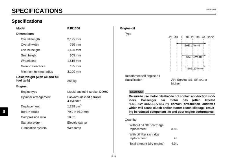
8-1
8
EAU01038
8-SPECIFICATIONS
Specifications CS-01E
Model FJR1300
Dimensions
Overall length 2,195 mm
Overall width 760 mm
Overall height 1,420 mm
Seat height 805 mm
Wheelbase 1,515 mm
Ground clearance 135 mm
Minimum turning radius 3,100 mm
Basic weight (with oil and full fuel tank) 268 kg
Engine
Engine type Liquid-cooled 4-stroke, DOHC
Cylinder arrangement Forward-inclined parallel 4-cylinder
Displacement 1,298 cm3
Bore × stroke 79.0 × 66.2 mm
Compression ratio 10.8:1
Starting system Electric starter
Lubrication system Wet sump
Engine oil
Type
Recommended engine oil classification API Service SE, SF, SG or
higher
Quantity
Without oil filter cartridge replacement 3.8 L
With oil filter cartridge replacement 4 L
Total amount (dry engine) 4.9 L
-20 -10 0 10 20 30 40 50 ˚C
SAE 15W-40
SAE 20W-40
SAE 10W-40
CAUTION:
Be sure to use motor oils that do not contain anti-friction mod-ifiers. Passenger car motor oils (often labeled“ENERGY CONSERVING II”) contain anti-friction additiveswhich will cause clutch and/or starter clutch slippage, result-ing in reduced component life and poor engine performance.
E_5jw.book Page 1 Friday, March 30, 2001 2:14 PM

SPECIFICATIONS
8-2
8
Final gear oil
Type Shaft drive gear oil (Part No.: 9079E-SH001-00)
Quantity 0.2 L
Cooling system capacity (total amount) 3.3 L
Air filter Dry type element
Fuel
Type Unleaded fuel only
Fuel tank capacity 25 L
Fuel reserve amount 5 L
Spark plug
Manufacturer/model NGK / CR8E or DENSO / U24ESR-N
Gap 0.7–0.8 mm
Clutch type Wet, multiple-disc
Transmission
Primary reduction system Helical gear
Primary reduction ratio 1.563
Secondary reduction system Shaft drive
Secondary reduction ratio 2.773
Transmission type Constant-mesh 5-speed
Operation Left foot
Gear ratio
1st 2.529
2nd 1.773
3rd 1.348
4th 1.077
5th 0.929
Chassis
Frame type Diamond
Caster angle 26°
Trail 109 mm
Tires
Front
Type Tubeless tire
Size 120/70 ZR17 (58 W)
Manufacturer/model Metzeler / MEZ4B FRONT
Bridgestone / BT020FN
Rear
Type Tubeless tire
Size 180/55 ZR17 (73 W)
Manufacturer/model Metzeler / MEZ4J
Bridgestone / BT020RN
E_5jw.book Page 2 Friday, March 30, 2001 2:14 PM
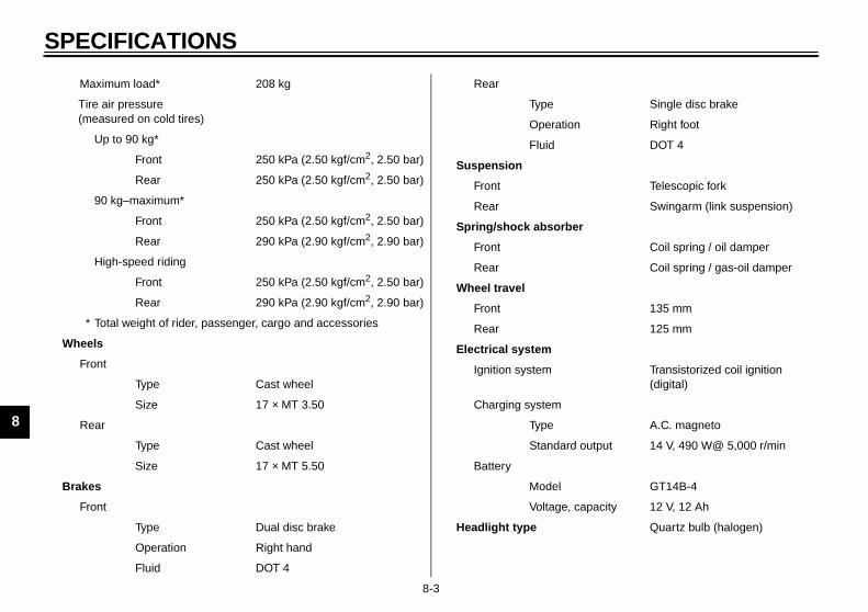
SPECIFICATIONS
8-3
8
Maximum load* 208 kg
Tire air pressure (measured on cold tires)
Up to 90 kg*
Front 250 kPa (2.50 kgf/cm2, 2.50 bar)
Rear 250 kPa (2.50 kgf/cm2, 2.50 bar)
90 kg–maximum*
Front 250 kPa (2.50 kgf/cm2, 2.50 bar)
Rear 290 kPa (2.90 kgf/cm2, 2.90 bar)
High-speed riding
Front 250 kPa (2.50 kgf/cm2, 2.50 bar)
Rear 290 kPa (2.90 kgf/cm2, 2.90 bar)
* Total weight of rider, passenger, cargo and accessories
Wheels
Front
Type Cast wheel
Size 17 × MT 3.50
Rear
Type Cast wheel
Size 17 × MT 5.50
Brakes
Front
Type Dual disc brake
Operation Right hand
Fluid DOT 4
Rear
Type Single disc brake
Operation Right foot
Fluid DOT 4
Suspension
Front Telescopic fork
Rear Swingarm (link suspension)
Spring/shock absorber
Front Coil spring / oil damper
Rear Coil spring / gas-oil damper
Wheel travel
Front 135 mm
Rear 125 mm
Electrical system
Ignition system Transistorized coil ignition (digital)
Charging system
Type A.C. magneto
Standard output 14 V, 490 W@ 5,000 r/min
Battery
Model GT14B-4
Voltage, capacity 12 V, 12 Ah
Headlight type Quartz bulb (halogen)
E_5jw.book Page 3 Friday, March 30, 2001 2:14 PM

SPECIFICATIONS
8-4
8
Bulb voltage, wattage × quantity
Headlight 12 V, 60/55 W × 2
Tail/brake light 12 V, 5/21 W × 2
Turn signal light 12 V, 21 W × 4
Meter lighting 14 V, 1.12 W × 4
Neutral indicator light 14 V, 1.12 W × 1
High beam indicator light 14 V, 1.12 W × 1
Turn signal indicator light 14 V, 1.4 W × 2
Engine trouble warning light 14 V, 1.12 W × 1
Oil level warning light 14 V, 1.12 W × 1
Fuses
Main fuse 50 A
Fuel injection system fuse 15 A
Headlight fuse 25 A
Signaling system fuse 15 A
Radiator fan fuse 15 A
Ignition fuse 10 A
Backup fuse (odometer and clock) 10 A
Windshield motor fuse 2 A
E_5jw.book Page 4 Friday, March 30, 2001 2:14 PM
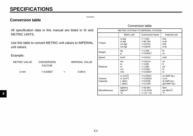
SPECIFICATIONS
8-5
8
EAU03941
Conversion table CS-03E
All specification data in this manual are listed in SI andMETRIC UNITS.
Use this table to convert METRIC unit values to IMPERIALunit values.
Example:
METRIC VALUE CONVERSION FACTOR
IMPERIAL VALUE
2 mm × 0.03937 = 0.08 in
Conversion tableMETRIC SYSTEM TO IMPERIAL SYSTEM
Metric unit Conversion factor Imperial unit
Torque
m·kgfm·kgfcm·kgfcm·kgf
× 7.233× 86.794× 0.0723× 0.8679
ft·lbin·lbft·lbin·lb
Weight kgg
× 2.205× 0.03527
lboz
Speed km/h × 0.6214 mi/h
Distance
kmmmcmmm
× 0.6214× 3.281× 1.094× 0.3937× 0.03937
miftydinin
Volume,Capacity
cc (cm3)cc (cm3)L (liter)L (liter)
× 0.03527× 0.06102× 0.8799× 0.2199
oz (IMP liq.)cu·inqt (IMP liq.)gal (IMP liq.)
Miscellaneouskgf/mmkgf/cm2
°C
× 55.997× 14.2234× 1.8 + 32
lb/inpsi (lb/in2)°F
E_5jw.book Page 5 Friday, March 30, 2001 2:14 PM

CONSUMER INFORMATION
9
Identification numbers ....................................................................... 9-1Key identification number .................................................................. 9-1Vehicle identification number ............................................................. 9-1Model label ........................................................................................ 9-2Motorcycle noise regulation (for Australia) ........................................ 9-2
E_5jw.book Page 1 Friday, March 30, 2001 2:14 PM

9-1
9
EAU01039
9-CONSUMER INFORMATIONEAU02944
Identification numbers Record the key identification number,vehicle identification number and mod-el label information in the spaces pro-vided below for assistance whenordering spare parts from a Yamahadealer or for reference in case the vehi-cle is stolen.
1. KEY IDENTIFICATION NUMBER:CA-02E
2. VEHICLE IDENTIFICATION NUMBER:
CA-02E
3. MODEL LABEL INFORMATION:CA-01E
EAU01041
Key identification number The key identification number isstamped into the key tag. Record thisnumber in the space provided and useit for reference when ordering a newkey.
EAU01043
Vehicle identification number The vehicle identification number isstamped into the steering head pipe.Record this number in the spaceprovided.
NOTE:_
The vehicle identification number isused to identify your motorcycle andmay be used to register your motor-cycle with the licensing authority inyour area. _
1. Key identification number 1. Vehicle identification number
E_5jw.book Page 1 Friday, March 30, 2001 2:14 PM

CONSUMER INFORMATION
9-2
9
EAU01804
Model label The model label is affixed to the frameunder the rider seat. (See page 3-10 forrider seat removal and installation pro-cedures.) Record the information onthis label in the space provided. This in-formation will be needed when orderingspare parts from a Yamaha dealer.
EAU01388
Motorcycle noise regulation (for Australia) TAMPERING WITH NOISE CON-TROL SYSTEM PROHIBITED:Owners are warned that the law mayprohibit:(a) The removal or rendering inopera-
tive by any person other than forpurposes of maintenance, repairor replacement, of any device orelement of design incorporatedinto any new vehicle for the pur-pose of noise control prior to itssale or delivery to the ultimate pur-chaser or while it is in use; and
(b) The use of the vehicle after suchdevice or element of design hasbeen removed or rendered inoper-ative by any person.
1. Model label
E_5jw.book Page 2 Friday, March 30, 2001 2:14 PM
INDEX
AAir filter element, cleaning......................6-15
BBattery ...................................................6-29Brake and clutch fluid levels, checking...6-23Brake and clutch fluids, changing...........6-24Brake and clutch levers, checking and
lubricating ............................................6-25Brake and shift pedals, checking and
lubricating ............................................6-25Brake lever...............................................3-7Brake lever free play, adjusting ..............6-21Brake light switch (rear), adjusting .........6-22Brake pads, checking.............................6-22Brake pedal..............................................3-7Brake pedal position, adjusting ..............6-21
CCables, checking and lubricating............6-24Care.........................................................7-1Catalytic converter.....................................3-9Centerstand and sidestand,
checking and lubricating ......................6-26Clutch lever..............................................3-6Clutch lever free play .............................6-20Conversion table......................................8-5Coolant level, checking ..........................6-13Cowling and panels, removing and
installing ................................................6-5
DDimmer switch......................................... 3-5Display, multi-function.............................. 3-3
EEngine break-in ....................................... 5-3Engine idling speed, checking ............... 6-16Engine oil and oil filter cartridge ............... 6-9Engine stop switch................................... 3-5Engine trouble warning light .................... 3-2
FFinal gear oil.......................................... 6-12Front and rear suspension settings........ 3-15Front fork, adjusting............................... 3-11Front fork, checking ............................... 6-27Fuel ......................................................... 3-9Fuel consumption, tips for reducing ......... 5-3Fuel tank cap........................................... 3-8Fuses, replacing .................................... 6-30
HHandlebar switches ................................. 3-5Headlight bulb, replacing ....................... 6-31High beam indicator light ......................... 3-2Horn switch ............................................. 3-5
IIdentification numbers ............................. 9-1Ignition circuit cut-off system.................. 3-17Indicator and warning lights ..................... 3-2
KKey identification number .........................9-1
LLabels, location ........................................1-7Locks for optional side cases and
travel trunk...........................................3-16
MMain switch/steering lock .........................3-1Model label ..............................................9-2
NNeutral indicator light ...............................3-2Noise regulation (for Australia) .................9-2
OOil level warning light ...............................3-2
PParking.....................................................5-4Part locations ...........................................2-1Pass switch..............................................3-5Periodic maintenance and lubrication
chart ......................................................6-2Pre-operation check list............................4-1
SSafety information ....................................1-1Seats .......................................................3-9
Passenger seat.................................3-10Rider seat ...........................................3-9
Shifting.....................................................5-2Shift pedal................................................3-6
E_5jw.book Page 1 Friday, March 30, 2001 2:14 PM

INDEX
Shock absorber assembly, adjusting ..... 3-13Sidestand .............................................. 3-16Spark plugs, checking ............................. 6-8Specifications .......................................... 8-1Speedometer........................................... 3-3Starting a cold engine.............................. 5-1Start switch.............................................. 3-5Steering, checking ................................. 6-27Storage.................................................... 7-4Storage compartment ............................ 3-10Suspension (rear), lubricating ................ 6-26
TTachometer ............................................. 3-3Tail/brake light bulb, replacing ............... 6-32Throttle cable free play, adjusting .......... 6-17Throttle grip and cable, checking and
lubricating............................................ 6-25Tires ...................................................... 6-17Tool kit..................................................... 6-1Troubleshooting..................................... 6-33Troubleshooting charts .......................... 6-34Turn signal indicator lights ....................... 3-2Turn signal light bulb, replacing ............. 6-33Turn signal switch.................................... 3-5
VValve clearance, adjusting..................... 6-17Vehicle identification number ................... 9-1
WWheel bearings, checking ..................... 6-28Wheels.................................................. 6-20Windshield position adjusting switch ....... 3-5
E_5jw.book Page 2 Friday, March 30, 2001 2:14 PM

H_5KS_Toc0.fm Page 2 Monday, August 21, 2000 11:11 AM

H_5KS_Toc0.fm Page 2 Monday, August 21, 2000 11:11 AM

5JW-28199-20
FJR1300N
OWNER’S MANUAL
PRINTED ON RECYCLED PAPER
YAMAHA MOTOR CO., LTD.
PRINTED IN JAPAN2001 · 3 - 0.3 × 1 CR
(E)