Embed Size (px)
Citation preview
- 1 –
________________________________________________________________________
Wasserdosiercomputer FL-DIGI-MODUL
Franz Ludwig Gesellschaft für Mess- und Regeltechnik mbH * Budenheimer Straße 1 * 55124 Mainz-Gonsenheim * Telefon (0 61 31) 910 46-0 * Fax (0 61 31) 910 46-24 * [email protected]
FL-DIGI-MODULE
INDEX PAGE: 2 TECHNICAL DATA 2 PROCESS INTEGRATION / VISUALIZATION 3 GENERAL FUNCTIONS 3 1. PARAMETERING OF FL-DIGI-MODULE VIA EXTERNAL COMPUTER 3 1.1 GENERALS 3 1.2 SYSTEM REQUIREMENTS 3 1.3 INSTALLATION REMARKS 3 1.4 PARAMETER’S SAVING AND OUTPUT IN THE MODULE 4 1.5 STARTUP PAGE / SCREEN 5 1.6 DISPLAYING OF CURRENT MEASURE VALUES/MIXING DATA 5 1.6.1 MIXER 6 1.6.2 AGGREGATE 7 1.7 CALIBRATION MIXER 7 1.7.1 CALIBRATION MIXER BY SOFTWARE 8 1.7.2 CALIBRATION MIXER BY CONTROL 8 1.7.3 MANUALLY CORRECTION OF AN EXISTING CALIBRATION GRAPH 9 1.8 CALIBRATION AGGREGATE MATERIAL 10 1.8.1 AUTOMATICALLY CALIBRATION 10 1.8.2 MANUALLY CALIBRATION PROCESS 11 1.9 PROTOCOLING 12 1.10 PROBE CHECK 13 2. CLAMP DIAGRAM FL-DIGI-MODULE 13 3. CONNECTION SCHEME OF PROBE CABLE 14-16 4. SELECTION OF INSTALLATION PLACE ON DIFFERENT MIXER TYPES 17-18 5. INSTALLATION MICROWAVE MOISTURE PROBE / AGGREGATE MATERIAL 19 6. EXCHANGE OF MEASURE HEAD
20-21 7. INTERFACE DESCRIPTION / RS232-485 22-24 8. INTERFACE DESCRIPTION ETHERNET (ONLY OPTIONALLY) 25-26 9. THE SERVICE PAGE
26 10. ERROR SHOOTING
When starting-up the FL-DIGI-MODUL please pay attention to:
- Before starting the evaluating software, connect the MODUL to the evaluation unit to avoid an error message after opening the software.
- To enable a communication with the MODUL, a COM-PORT has to be selected in the evaluation software:
FL-DIGI-MODUL: “Operation mode“ > „Service“ > ”Password: 55124” > “Modul 1-9” > select COM-PORT
- 2 –
________________________________________________________________________
Wasserdosiercomputer FL-DIGI-MODUL
Franz Ludwig Gesellschaft für Mess- und Regeltechnik mbH * Budenheimer Straße 1 * 55124 Mainz-Gonsenheim * Telefon (0 61 31) 910 46-0 * Fax (0 61 31) 910 46-24 * [email protected]
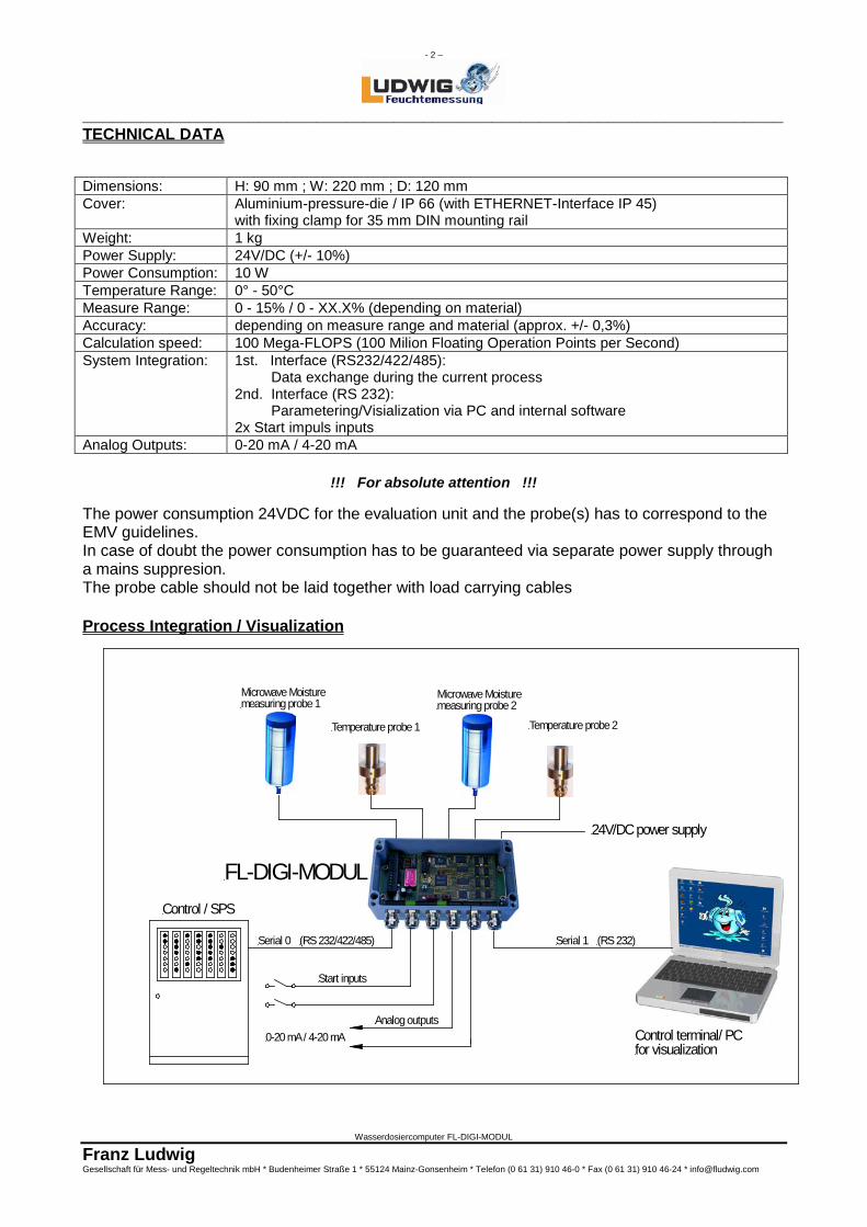
TECHNICAL DATA Dimensions: H: 90 mm ; W: 220 mm ; D: 120 mm Cover: Aluminium-pressure-die / IP 66 (with ETHERNET-Interface IP 45)
with fixing clamp for 35 mm DIN mounting rail Weight: 1 kg Power Supply: 24V/DC (+/- 10%) Power Consumption: 10 W Temperature Range: 0° - 50°C Measure Range: 0 - 15% / 0 - XX.X% (depending on material) Accuracy: depending on measure range and material (approx. +/- 0,3%) Calculation speed: 100 Mega-FLOPS (100 Milion Floating Operation Points per Second) System Integration: 1st. Interface (RS232/422/485):
Data exchange during the current process 2nd. Interface (RS 232): Parametering/Visialization via PC and internal software 2x Start impuls inputs
Analog Outputs: 0-20 mA / 4-20 mA
!!! For absolute attention !!!
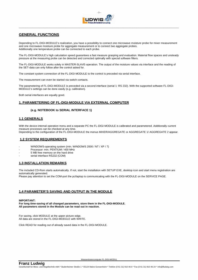
The power consumption 24VDC for the evaluation unit and the probe(s) has to correspond to the EMV guidelines. In case of doubt the power consumption has to be guaranteed via separate power supply through a mains suppresion. The probe cable should not be laid together with load carrying cables Process Integration / Visualization
Serial 0 Serial 1(RS 232/422/485) (RS 232)
Temperature probe 1 Temperature probe 2
FL-DIGI-MODUL
Start inputs
Analog outputs0-20 mA / 4-20 mA
Microwave Moisturemeasuring probe 1
Microwave Moisturemeasuring probe 2
24V/DC power supply
Control terminal/ PCfor visualization
Control / SPS
- 3 –
________________________________________________________________________
Wasserdosiercomputer FL-DIGI-MODUL
Franz Ludwig Gesellschaft für Mess- und Regeltechnik mbH * Budenheimer Straße 1 * 55124 Mainz-Gonsenheim * Telefon (0 61 31) 910 46-0 * Fax (0 61 31) 910 46-24 * [email protected]
GENERAL FUNCTIONS Depending to FL-DIGI-MODULE’s realization, you have a possibility to connect one microwave moisture probe for mixer measurement and one microwave moisture probe for aggregate measurement or to connect two aggregate probes. Additionally one temperature probe can be connected to each probe. The FL-DIGI-MODULE’s high calculation speed guarantees a fast measure grasping and evaluation. Material flow spaces and unsteady pressure at the measuring probe can be detected and corrected optimally with special software filters. The FL-DIGI-MODULE works solely in MASTER-SLAVE-operation. The output of the moisture values via interface and the reading of the SET-data can only follow after the control asked for. The constant system connection of the FL-DIGI-MODULE to the control is preceded via serial interface. The measurement can even be started via switch contacts. The parametering of FL-DIGI-MODULE is preceded via a second interface (serial 1: RS 232). With the supported software FL-DIGI-MODULE’s settings can be done easily (e.g. calibration). Both serial interfaces are equally good.
1. PARAMETERING OF FL-DIGI-MODULE VIA EXTERNAL COMPUTER
(e.g. NOTEBOOK to SERIAL INTERFACE 1) 1.1 GENERALS With the device-internal operation menu and a separate PC the FL-DIGI-MODULE is calibrated and parametered. Additionally current measure processes can be checked at any time. Depending to the configuration of the FL-DIGI-MODULE the menus MIXER/AGGREGATE or AGGREGATE 1/ AGGREGATE 2 appear. 1.2 SYSTEM REQUIREMENTS
- WINDOWS-operating system (min. WINDOWS 2000 / NT / XP / 7) - Processor: min. PENTIUM / 400 MHz - 5 MB free memory on the hard drive - serial interface RS232 (COM) 1.3 INSTALLATION REMARKS The included CD-Rom starts automatically. If not, start the installation with SETUP.EXE, desktop icon and start menu registration are automatically generated. Please pay attention to set the COM-port the pc/laptop is communicating with the FL-DIGI-MODULE on the SERVICE PAGE.
1.4 PARAMETER’S SAVING AND OUTPUT IN THE MODULE IMPORTANT: For long time-saving of all changed parameters, store them in the FL-DIGI-MODULE. All parameters stored in the Module can be read out in reaction.
For saving, click MODULE at the upper picture edge. All data are stored in the FL-DIGI-MODULE with WRITE. Click READ for reading out of already saved data in the FL-DIGI-MODULE.
- 4 –
________________________________________________________________________
Wasserdosiercomputer FL-DIGI-MODUL
Franz Ludwig Gesellschaft für Mess- und Regeltechnik mbH * Budenheimer Straße 1 * 55124 Mainz-Gonsenheim * Telefon (0 61 31) 910 46-0 * Fax (0 61 31) 910 46-24 * [email protected]
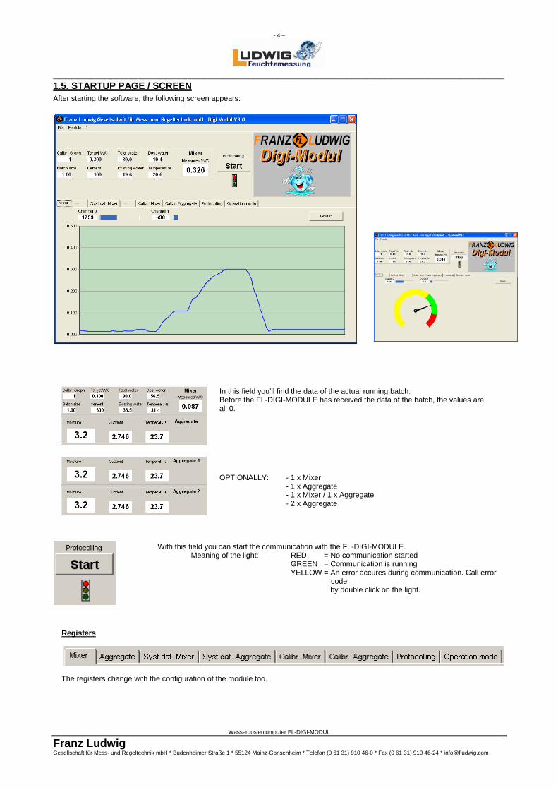
1.5. STARTUP PAGE / SCREEN After starting the software, the following screen appears:
In this field you’ll find the data of the actual running batch. Before the FL-DIGI-MODULE has received the data of the batch, the values are all 0. OPTIONALLY: - 1 x Mixer - 1 x Aggregate - 1 x Mixer / 1 x Aggregate - 2 x Aggregate
With this field you can start the communication with the FL-DIGI-MODULE. Meaning of the light: RED = No communication started GREEN = Communication is running YELLOW = An error accures during communication. Call error code by double click on the light.
Registers
The registers change with the configuration of the module too.
- 5 –
________________________________________________________________________
Wasserdosiercomputer FL-DIGI-MODUL
Franz Ludwig Gesellschaft für Mess- und Regeltechnik mbH * Budenheimer Straße 1 * 55124 Mainz-Gonsenheim * Telefon (0 61 31) 910 46-0 * Fax (0 61 31) 910 46-24 * [email protected]
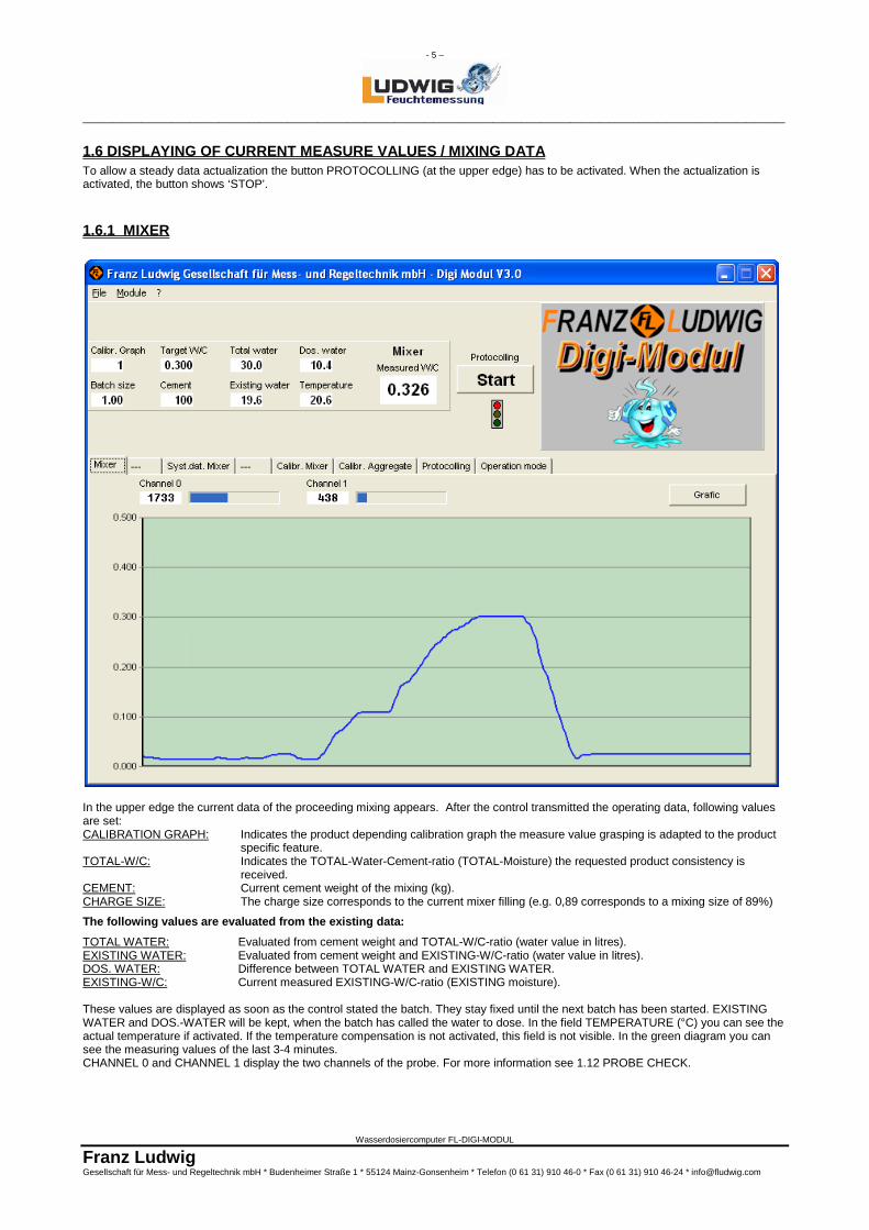
1.6 DISPLAYING OF CURRENT MEASURE VALUES / MIXING DATA To allow a steady data actualization the button PROTOCOLLING (at the upper edge) has to be activated. When the actualization is activated, the button shows ‘STOP’.
1.6.1 MIXER
In the upper edge the current data of the proceeding mixing appears. After the control transmitted the operating data, following values are set: CALIBRATION GRAPH: Indicates the product depending calibration graph the measure value grasping is adapted to the product
specific feature. TOTAL-W/C: Indicates the TOTAL-Water-Cement-ratio (TOTAL-Moisture) the requested product consistency is
received. CEMENT: Current cement weight of the mixing (kg). CHARGE SIZE: The charge size corresponds to the current mixer filling (e.g. 0,89 corresponds to a mixing size of 89%)
The following values are evaluated from the existing data: TOTAL WATER: Evaluated from cement weight and TOTAL-W/C-ratio (water value in litres). EXISTING WATER: Evaluated from cement weight and EXISTING-W/C-ratio (water value in litres). DOS. WATER: Difference between TOTAL WATER and EXISTING WATER. EXISTING-W/C: Current measured EXISTING-W/C-ratio (EXISTING moisture). These values are displayed as soon as the control stated the batch. They stay fixed until the next batch has been started. EXISTING WATER and DOS.-WATER will be kept, when the batch has called the water to dose. In the field TEMPERATURE (°C) you can see the actual temperature if activated. If the temperature compensation is not activated, this field is not visible. In the green diagram you can see the measuring values of the last 3-4 minutes. CHANNEL 0 and CHANNEL 1 display the two channels of the probe. For more information see 1.12 PROBE CHECK.
- 6 –
________________________________________________________________________
Wasserdosiercomputer FL-DIGI-MODUL
Franz Ludwig Gesellschaft für Mess- und Regeltechnik mbH * Budenheimer Straße 1 * 55124 Mainz-Gonsenheim * Telefon (0 61 31) 910 46-0 * Fax (0 61 31) 910 46-24 * [email protected]
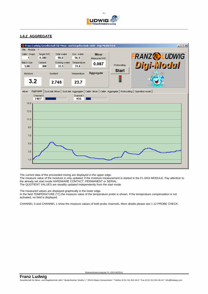
1.6.2 AGGREGATE
The current data of the proceeded mixing are displayed in the upper edge. The measure value of the moisture is only updated, if the moisture measurement is started in the FL-DIGI-MODULE. Pay attention to the already set start mode HARDWARE CONTACT, PERMANENT or SERIAL. The QUOTIENT VALUES are steadily updated independently from the start mode. The measured values are displayed graphically in the lower edge. In the field TEMPERATURE (°C) the measure value of the temperature probe is shown. If the temperature compensation is not activated, no field is displayed. CHANNEL 0 and CHANNEL 1 show the measure values of both probe channels. More details please see 1.12 PROBE CHECK.
- 7 –
________________________________________________________________________
Wasserdosiercomputer FL-DIGI-MODUL
Franz Ludwig Gesellschaft für Mess- und Regeltechnik mbH * Budenheimer Straße 1 * 55124 Mainz-Gonsenheim * Telefon (0 61 31) 910 46-0 * Fax (0 61 31) 910 46-24 * [email protected]
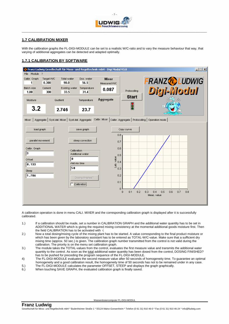
1.7 CALIBRATION MIXER With the calibration graphs the FL-DIGI-MODULE can be set to a realistic W/C-ratio and to vary the measure behaviour that way, that varying of additional aggregates can be detected and adapted optimally.
1.7.1 CALIBRATION BY SOFTWARE
A calibration operation is done in menu CALI. MIXER and the corresponding calibration graph is displayed after it is successfully calibrated. 1.) If a calibration should be made, set a number in CALIBRATION GRAPH and the additional water quantity has to be set in
ADDITIONAL WATER which is giving the required mixing consistency at the momental additional goods moisture first. Then the field CALIBRATION has to be activated with √.
2.) Now a total dosing/mixing cycle of the mixing plant has to be started. A value corresponding to the final product moisture or which has been given by the laboratory assistant has to be entered as TOTAL-W/C-value. Make sure that a sufficient dry mixing time (approx. 50 sec.) is given. The calibration graph number transmitted from the control is not valid during the calibration. The priority is on the menu set calibration graph.
3.) The module takes the TOTAL-values from the control, evaluates the first measure value and transmits the additional water quantity to the control. As soon as the total additional water quantity has been dosed from the control, DOSING FINISHED? has to be pushed for preceding the program sequence of the FL-DIGI-MODULE.
4) The FL-DIGI-MODULE evaluates the second measure value after 50 seconds of homogeneity time. To guarantee an optimal homogeneity and a good calibration result, the homogeneity time of 50 seconds has not to be remained under in any case.
5.) The FL-DIGI-MODULE calculates the parameter OFFSET, STEEP and displays the graph graphically. 6.) When touching SAVE GRAPH, the evaluated calibration graph is finally saved.
- 8 –
________________________________________________________________________
Wasserdosiercomputer FL-DIGI-MODUL
Franz Ludwig Gesellschaft für Mess- und Regeltechnik mbH * Budenheimer Straße 1 * 55124 Mainz-Gonsenheim * Telefon (0 61 31) 910 46-0 * Fax (0 61 31) 910 46-24 * [email protected]
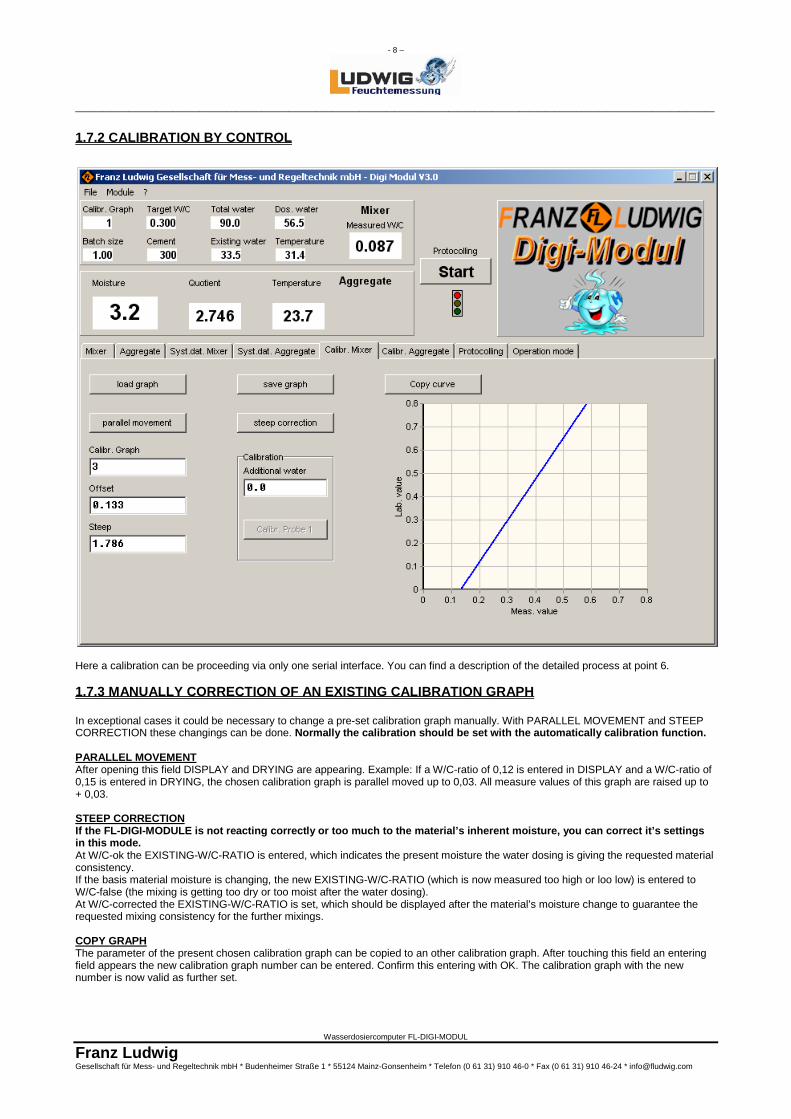
1.7.2 CALIBRATION BY CONTROL
Here a calibration can be proceeding via only one serial interface. You can find a description of the detailed process at point 6. 1.7.3 MANUALLY CORRECTION OF AN EXISTING CALIBRATION GRAPH In exceptional cases it could be necessary to change a pre-set calibration graph manually. With PARALLEL MOVEMENT and STEEP CORRECTION these changings can be done. Normally the calibration should be set with the automatically calibration function. PARALLEL MOVEMENT After opening this field DISPLAY and DRYING are appearing. Example: If a W/C-ratio of 0,12 is entered in DISPLAY and a W/C-ratio of 0,15 is entered in DRYING, the chosen calibration graph is parallel moved up to 0,03. All measure values of this graph are raised up to + 0,03. STEEP CORRECTION If the FL-DIGI-MODULE is not reacting correctly or too much to the material’s inherent moisture, you can correct it’s settings in this mode. At W/C-ok the EXISTING-W/C-RATIO is entered, which indicates the present moisture the water dosing is giving the requested material consistency. If the basis material moisture is changing, the new EXISTING-W/C-RATIO (which is now measured too high or loo low) is entered to W/C-false (the mixing is getting too dry or too moist after the water dosing). At W/C-corrected the EXISTING-W/C-RATIO is set, which should be displayed after the material’s moisture change to guarantee the requested mixing consistency for the further mixings. COPY GRAPH The parameter of the present chosen calibration graph can be copied to an other calibration graph. After touching this field an entering field appears the new calibration graph number can be entered. Confirm this entering with OK. The calibration graph with the new number is now valid as further set.
- 9 –
________________________________________________________________________
Wasserdosiercomputer FL-DIGI-MODUL
Franz Ludwig Gesellschaft für Mess- und Regeltechnik mbH * Budenheimer Straße 1 * 55124 Mainz-Gonsenheim * Telefon (0 61 31) 910 46-0 * Fax (0 61 31) 910 46-24 * [email protected]
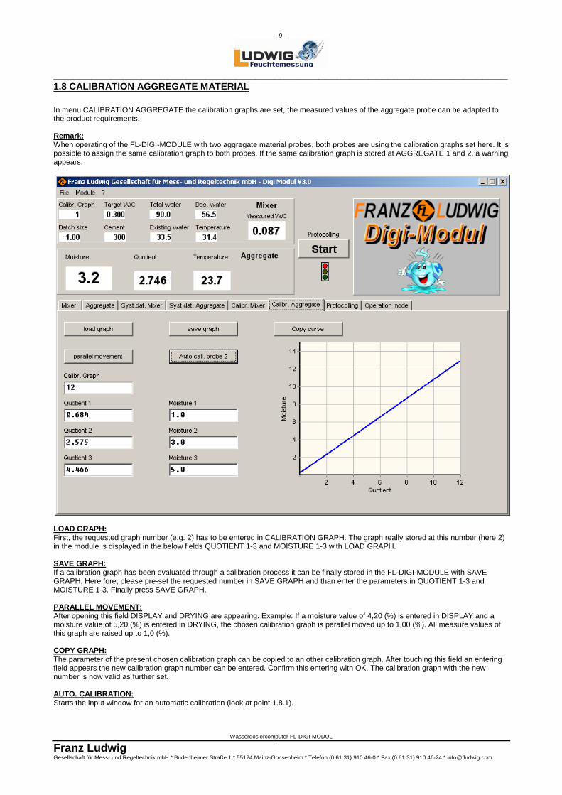
1.8 CALIBRATION AGGREGATE MATERIAL In menu CALIBRATION AGGREGATE the calibration graphs are set, the measured values of the aggregate probe can be adapted to the product requirements. Remark: When operating of the FL-DIGI-MODULE with two aggregate material probes, both probes are using the calibration graphs set here. It is possible to assign the same calibration graph to both probes. If the same calibration graph is stored at AGGREGATE 1 and 2, a warning appears.
LOAD GRAPH: First, the requested graph number (e.g. 2) has to be entered in CALIBRATION GRAPH. The graph really stored at this number (here 2) in the module is displayed in the below fields QUOTIENT 1-3 and MOISTURE 1-3 with LOAD GRAPH. SAVE GRAPH: If a calibration graph has been evaluated through a calibration process it can be finally stored in the FL-DIGI-MODULE with SAVE GRAPH. Here fore, please pre-set the requested number in SAVE GRAPH and than enter the parameters in QUOTIENT 1-3 and MOISTURE 1-3. Finally press SAVE GRAPH. PARALLEL MOVEMENT: After opening this field DISPLAY and DRYING are appearing. Example: If a moisture value of 4,20 (%) is entered in DISPLAY and a moisture value of 5,20 (%) is entered in DRYING, the chosen calibration graph is parallel moved up to 1,00 (%). All measure values of this graph are raised up to 1,0 (%). COPY GRAPH: The parameter of the present chosen calibration graph can be copied to an other calibration graph. After touching this field an entering field appears the new calibration graph number can be entered. Confirm this entering with OK. The calibration graph with the new number is now valid as further set. AUTO. CALIBRATION: Starts the input window for an automatic calibration (look at point 1.8.1).
- 10 –
________________________________________________________________________
Wasserdosiercomputer FL-DIGI-MODUL
Franz Ludwig Gesellschaft für Mess- und Regeltechnik mbH * Budenheimer Straße 1 * 55124 Mainz-Gonsenheim * Telefon (0 61 31) 910 46-0 * Fax (0 61 31) 910 46-24 * [email protected]
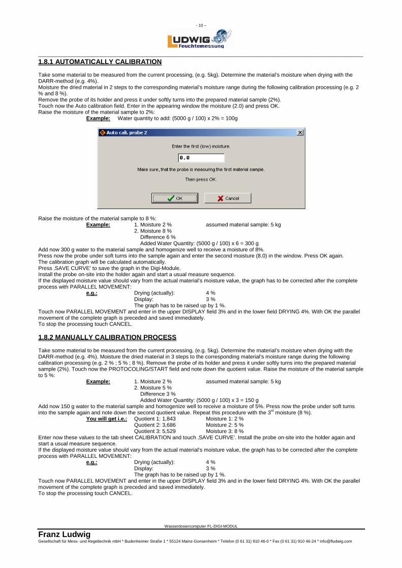
1.8.1 AUTOMATICALLY CALIBRATION Take some material to be measured from the current processing, (e.g. 5kg). Determine the material’s moisture when drying with the DARR-method (e.g. 4%). Moisture the dried material in 2 steps to the corresponding material’s moisture range during the following calibration processing (e.g. 2 % and 8 %). Remove the probe of its holder and press it under softly turns into the prepared material sample (2%). Touch now the Auto calibration field. Enter in the appearing window the moisture (2.0) and press OK. Raise the moisture of the material sample to 2%: Example: Water quantity to add: (5000 g / 100) x 2% = 100g
Raise the moisture of the material sample to 8 %: Example: 1. Moisture 2 % assumed material sample: 5 kg 2. Moisture 8 % Difference 6 % Added Water Quantity: (5000 g / 100) x 6 = 300 g Add now 300 g water to the material sample and homogenize well to receive a moisture of 8%. Press now the probe under soft turns into the sample again and enter the second moisture (8.0) in the window. Press OK again. The calibration graph will be calculated automatically. Press ‚SAVE CURVE’ to save the graph in the Digi-Module. Install the probe on-site into the holder again and start a usual measure sequence. If the displayed moisture value should vary from the actual material’s moisture value, the graph has to be corrected after the complete process with PARALLEL MOVEMENT: e.g.: Drying (actually): 4 % Display: 3 % The graph has to be raised up by 1 %. Touch now PARALLEL MOVEMENT and enter in the upper DISPLAY field 3% and in the lower field DRYING 4%. With OK the parallel movement of the complete graph is preceded and saved immediately. To stop the processing touch CANCEL. 1.8.2 MANUALLY CALIBRATION PROCESS Take some material to be measured from the current processing, (e.g. 5kg). Determine the material’s moisture when drying with the DARR-method (e.g. 4%). Moisture the dried material in 3 steps to the corresponding material’s moisture range during the following calibration processing (e.g. 2 % ; 5 % ; 8 %). Remove the probe of its holder and press it under softly turns into the prepared material sample (2%). Touch now the PROTOCOLING/START field and note down the quotient value. Raise the moisture of the material sample to 5 %: Example: 1. Moisture 2 % assumed material sample: 5 kg 2. Moisture 5 % Difference 3 % Added Water Quantity: (5000 g / 100) x 3 = 150 g Add now 150 g water to the material sample and homogenize well to receive a moisture of 5%. Press now the probe under soft turns into the sample again and note down the second quotient value. Repeat this procedure with the 3rd moisture (8 %). You will get i.e.: Quotient 1: 1,843 Moisture 1: 2 % Quotient 2: 3,686 Moisture 2: 5 % Quotient 3: 5,529 Moisture 3: 8 % Enter now these values to the tab sheet CALIBRATION and touch ‚SAVE CURVE’. Install the probe on-site into the holder again and start a usual measure sequence. If the displayed moisture value should vary from the actual material’s moisture value, the graph has to be corrected after the complete process with PARALLEL MOVEMENT: e.g.: Drying (actually): 4 % Display: 3 % The graph has to be raised up by 1 %. Touch now PARALLEL MOVEMENT and enter in the upper DISPLAY field 3% and in the lower field DRYING 4%. With OK the parallel movement of the complete graph is preceded and saved immediately. To stop the processing touch CANCEL.
- 11 –
________________________________________________________________________
Wasserdosiercomputer FL-DIGI-MODUL
Franz Ludwig Gesellschaft für Mess- und Regeltechnik mbH * Budenheimer Straße 1 * 55124 Mainz-Gonsenheim * Telefon (0 61 31) 910 46-0 * Fax (0 61 31) 910 46-24 * [email protected]
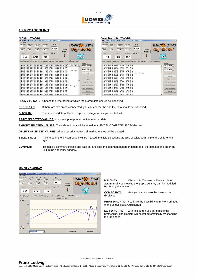
1.9 PROTOCOLING MIXER – VALUES AGGREGATE - VALUES
FROM / TO DATE: Choose the time period of which the stored data should be displayed. PROBE 1 / 2: If there are two probes connected, you can choose the one the data should be displayed. DIAGRAM: The selected data will be displayed in a diagram (see picture below). PRINT SELECTED VALUES: You see a print-preview of the selected data. EXPORT SELCTED VALUES: The selected data will be saved in an EXCEL-COMPATIBLE CSV-Format. DELETE SELECTED VALUES: After a security request all marked entries will be deleted. SELECT ALL: All entries of the chosen period will be marked. Multiple selections are also possible with help of the shift- or ctrl-
key. COMMENT: To make a comment choose one data set and click the comment button or double click the data set and enter the
text in the appearing window.
MIXER - DIAGRAM
MIN / MAX: MIN- and MAX-value will be calculated automatically by creating the graph, but they can be modified by clicking the values. COMBO BOX: Here you can choose the value to be displayed. PRINT DIAGRAM: You have the possibility to make a printout of the actual displayed diagram. EXIT DIAGRAM: With this button you get back to the protocoling. The diagram will be left automatically by changing the tab sheet.
- 12 –
________________________________________________________________________
Wasserdosiercomputer FL-DIGI-MODUL
Franz Ludwig Gesellschaft für Mess- und Regeltechnik mbH * Budenheimer Straße 1 * 55124 Mainz-Gonsenheim * Telefon (0 61 31) 910 46-0 * Fax (0 61 31) 910 46-24 * [email protected]
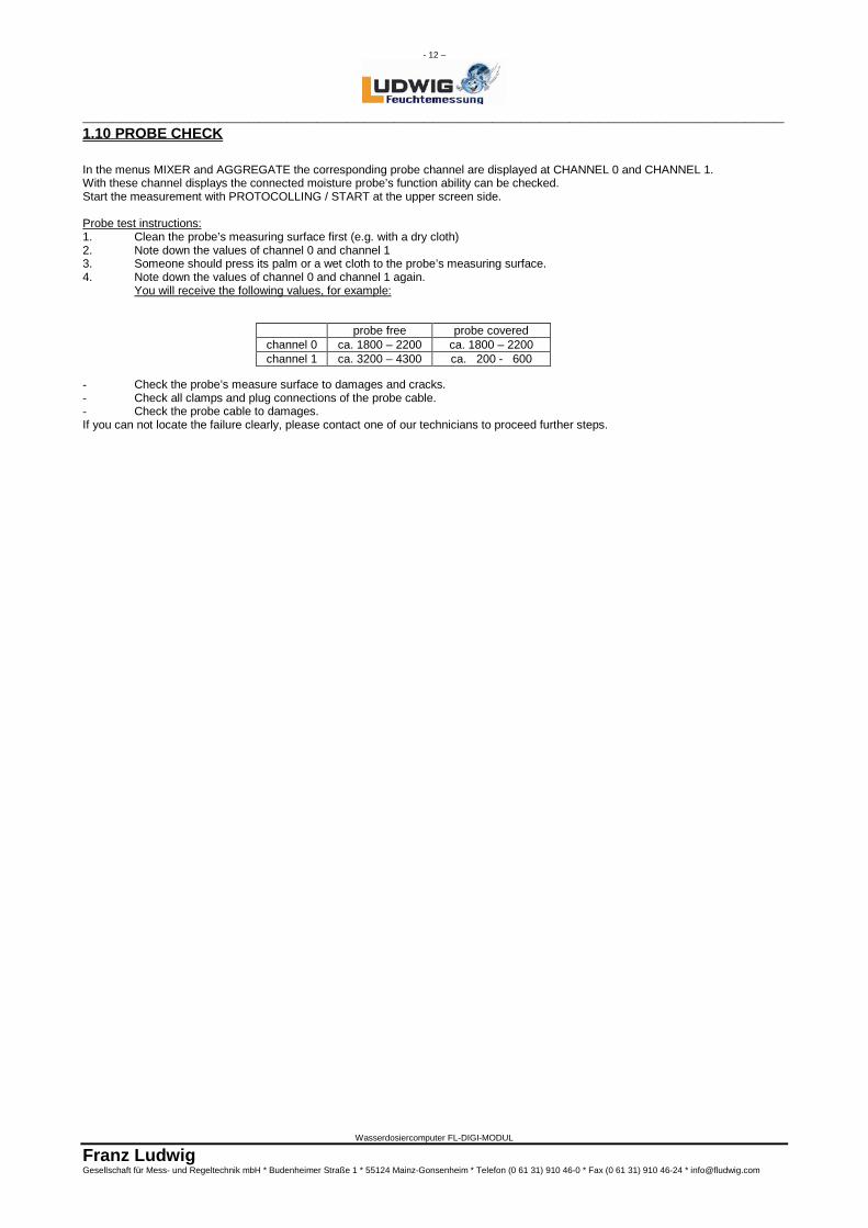
1.10 PROBE CHECK In the menus MIXER and AGGREGATE the corresponding probe channel are displayed at CHANNEL 0 and CHANNEL 1. With these channel displays the connected moisture probe’s function ability can be checked. Start the measurement with PROTOCOLLING / START at the upper screen side. Probe test instructions: 1. Clean the probe’s measuring surface first (e.g. with a dry cloth) 2. Note down the values of channel 0 and channel 1 3. Someone should press its palm or a wet cloth to the probe’s measuring surface. 4. Note down the values of channel 0 and channel 1 again.
You will receive the following values, for example:
- Check the probe’s measure surface to damages and cracks. - Check all clamps and plug connections of the probe cable. - Check the probe cable to damages. If you can not locate the failure clearly, please contact one of our technicians to proceed further steps.
probe free probe covered channel 0 ca. 1800 – 2200 ca. 1800 – 2200 channel 1 ca. 3200 – 4300 ca. 200 - 600
- 13 –
________________________________________________________________________
Wasserdosiercomputer FL-DIGI-MODUL
Franz Ludwig Gesellschaft für Mess- und Regeltechnik mbH * Budenheimer Straße 1 * 55124 Mainz-Gonsenheim * Telefon (0 61 31) 910 46-0 * Fax (0 61 31) 910 46-24 * [email protected]
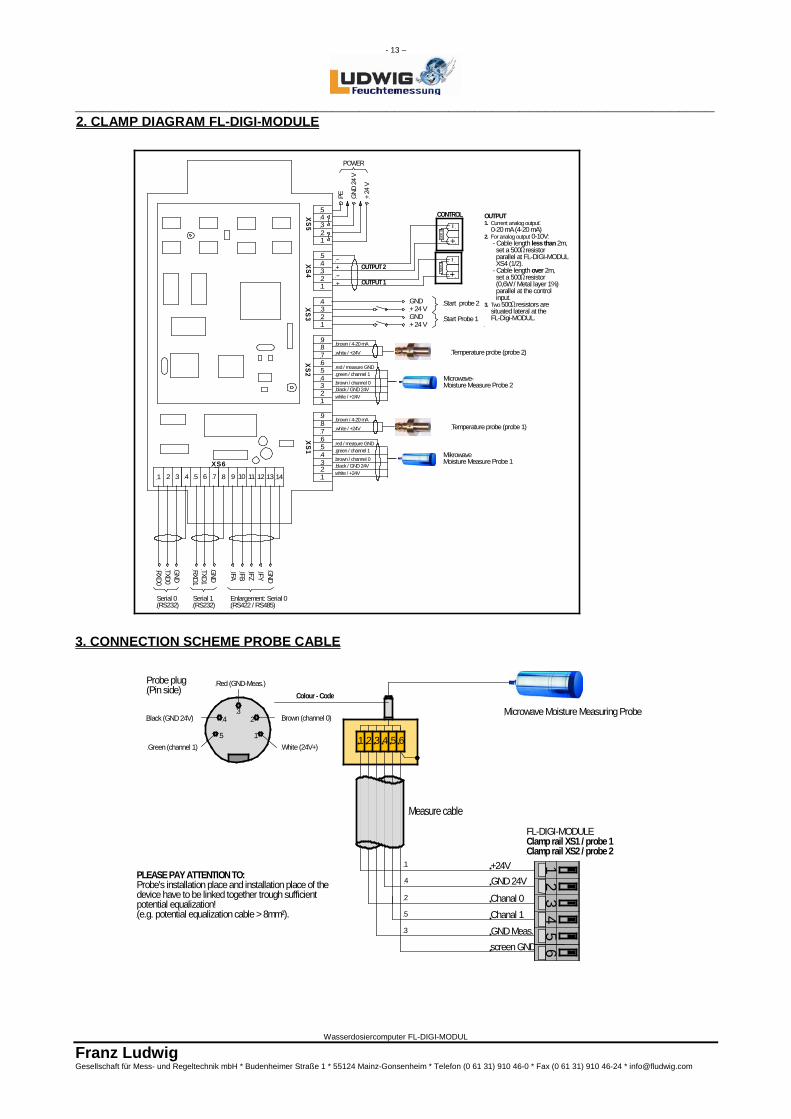
2. CLAMP DIAGRAM FL-DIGI-MODULE 3. CONNECTION SCHEME PROBE CABLE
Colour - Code
Probe plug(Pin side)
White (24V+)
Brown (channel 0)
Green (channel 1)
Black (GND 24V)
Red (GND-Meas.)
PLEASE PAY ATTENTION TO: Probe's installation place and installation place of the device have to be linked together trough sufficient potential equalization! (e.g. potential equalization cable > 8mm²).
1
4
3
1 2 3 4 5 6
2
5
1
23
4
5
screen GND
GND 24V
Chanal 1Chanal 0
GND Meas.
+24V 1 2
3 4
5 6
Microwave Moisture Measuring Probe
FL-DIGI-MODULEClamp rail XS1 / probe 1Clamp rail XS2 / probe 2
Measure cable
1 2 3 4 5 6 7 8 9 10 11 12 13
GND+ 24 VGND+ 24 V
Start probe 2
Start Probe 1
white / +24V
brown / 4-20 mA
white / +24V
brown / 4-20 mA
14
RXD0TXD0GND
GND
RXD1TXD1
IFA IFBIFZIFYGND
Serial 0(RS232)
Serial 1(RS232)
Enlargement: Serial 0(RS422 / RS485)
X S 6
white / +24Vblack / GND 24Vbrown / channel 0
green / channel 1red / measure GND
Microwave-Moisture Measure Probe 2
white / +24Vblack / GND 24Vbrown / channel 0
green / channel 1red / measure GND
Temperature probe (probe 1)
MikrowaveMoisture Measure Probe 1
Temperature probe (probe 2)
54321
54321
4321
987654321
987654321
X S 1X S 2
X S 3X S 4
X S 5
+ 24
V
GND
24 V
POWER
PE
+-
OUTPUT 1
CONTROL
OUTPUT 2+-
500 Ω
+-
500 Ω
+-
OUTPUT1. Current analog output: 0-20 mA (4-20 mA)2. For analog output 0-10V: - Cable length less than 2m, set a 500Ω resistor parallel at FL-DIGI-MODUL XS4 (1/2). - Cable length over 2m, set a 500Ω resistor (0,6W / Metal layer 1%) parallel at the control input. 3. Two 500Ω resistors are situated lateral at the FL-Digi-MODUL.
- 14 –
________________________________________________________________________
Wasserdosiercomputer FL-DIGI-MODUL
Franz Ludwig Gesellschaft für Mess- und Regeltechnik mbH * Budenheimer Straße 1 * 55124 Mainz-Gonsenheim * Telefon (0 61 31) 910 46-0 * Fax (0 61 31) 910 46-24 * [email protected]
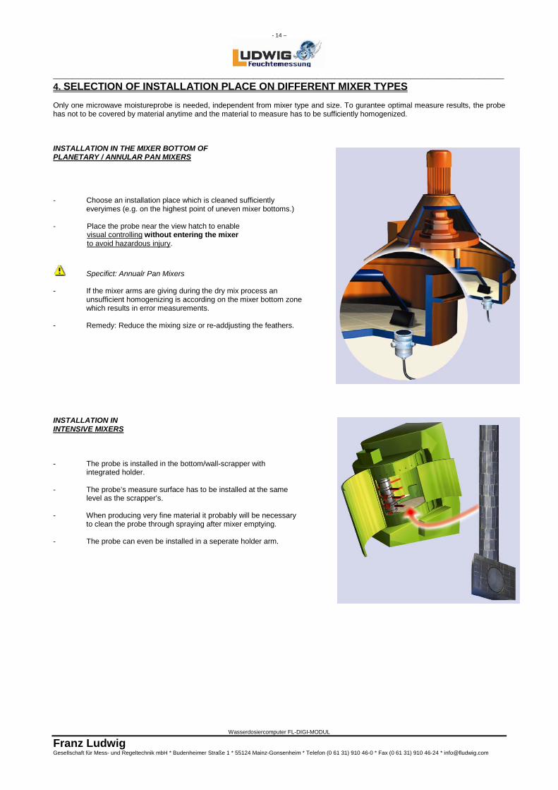
4. SELECTION OF INSTALLATION PLACE ON DIFFERENT MIXER TYPES Only one microwave moistureprobe is needed, independent from mixer type and size. To gurantee optimal measure results, the probe has not to be covered by material anytime and the material to measure has to be sufficiently homogenized. INSTALLATION IN THE MIXER BOTTOM OF PLANETARY / ANNULAR PAN MIXERS - Choose an installation place which is cleaned sufficiently
everyimes (e.g. on the highest point of uneven mixer bottoms.)
- Place the probe near the view hatch to enable visual controlling without entering the mixer to avoid hazardous injury.
Specifict: Annualr Pan Mixers - If the mixer arms are giving during the dry mix process an
unsufficient homogenizing is according on the mixer bottom zone which results in error measurements.
- Remedy: Reduce the mixing size or re-addjusting the feathers. INSTALLATION IN INTENSIVE MIXERS - The probe is installed in the bottom/wall-scrapper with integrated holder. - The probe’s measure surface has to be installed at the same level as the scrapper’s. - When producing very fine material it probably will be necessary
to clean the probe through spraying after mixer emptying. - The probe can even be installed in a seperate holder arm.
- 15 –
________________________________________________________________________
Wasserdosiercomputer FL-DIGI-MODUL
Franz Ludwig Gesellschaft für Mess- und Regeltechnik mbH * Budenheimer Straße 1 * 55124 Mainz-Gonsenheim * Telefon (0 61 31) 910 46-0 * Fax (0 61 31) 910 46-24 * [email protected]
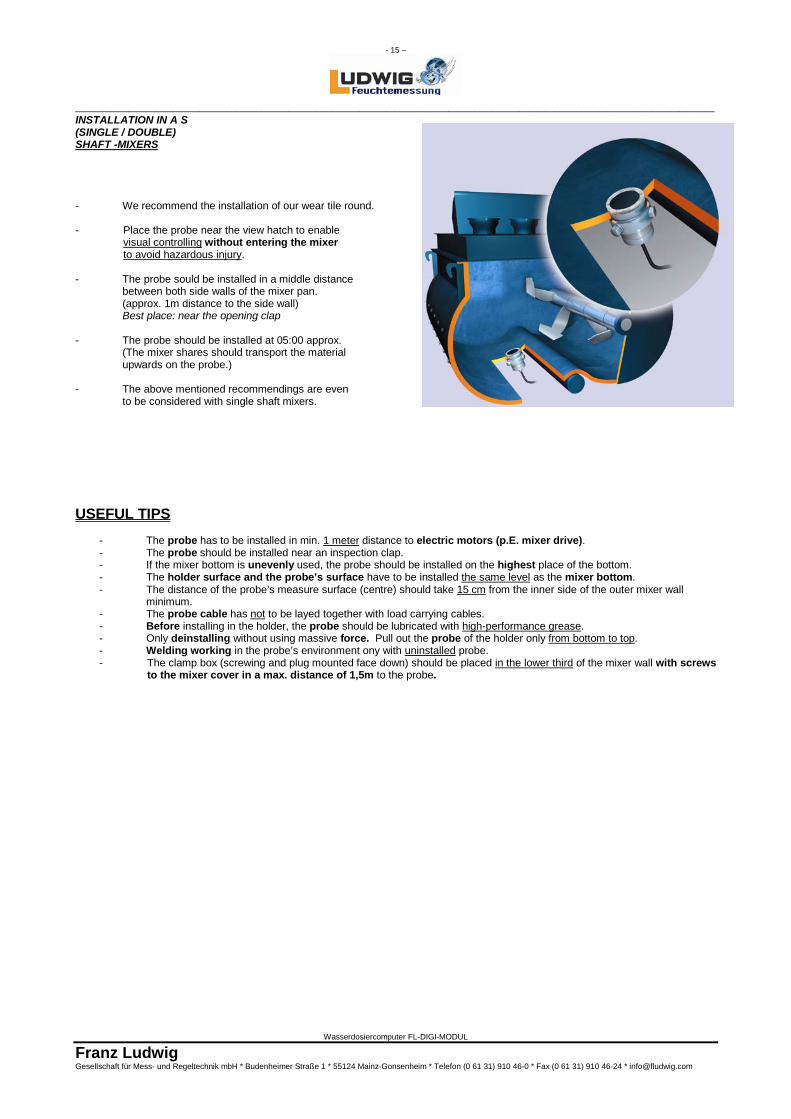
INSTALLATION IN A S (SINGLE / DOUBLE) SHAFT -MIXERS - We recommend the installation of our wear tile round. - Place the probe near the view hatch to enable
visual controlling without entering the mixer to avoid hazardous injury.
- The probe sould be installed in a middle distance
between both side walls of the mixer pan. (approx. 1m distance to the side wall) Best place: near the opening clap
- The probe should be installed at 05:00 approx. (The mixer shares should transport the material
upwards on the probe.) - The above mentioned recommendings are even
to be considered with single shaft mixers. USEFUL TIPS
- The probe has to be installed in min. 1 meter distance to electric motors (p.E. mixer drive). - The probe should be installed near an inspection clap. - If the mixer bottom is unevenly used, the probe should be installed on the highest place of the bottom. - The holder surface and the probe’s surface have to be installed the same level as the mixer bottom. - The distance of the probe’s measure surface (centre) should take 15 cm from the inner side of the outer mixer wall
minimum. - The probe cable has not to be layed together with load carrying cables. - Before installing in the holder, the probe should be lubricated with high-performance grease. - Only deinstalling without using massive force. Pull out the probe of the holder only from bottom to top. - Welding working in the probe’s environment ony with uninstalled probe. - The clamp box (screwing and plug mounted face down) should be placed in the lower third of the mixer wall with screws to the mixer cover in a max. distance of 1,5m to the probe.
- 16 –
________________________________________________________________________
Wasserdosiercomputer FL-DIGI-MODUL
Franz Ludwig Gesellschaft für Mess- und Regeltechnik mbH * Budenheimer Straße 1 * 55124 Mainz-Gonsenheim * Telefon (0 61 31) 910 46-0 * Fax (0 61 31) 910 46-24 * [email protected]
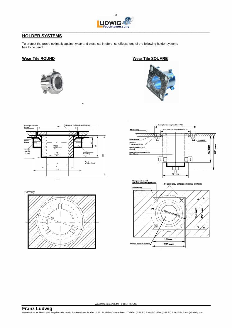
HOLDER SYSTEMS To protect the probe optimally against wear and electrical inteference effects, one of the following holder systems has to be used: Wear Tile ROUND Wear Tile SQUARE
Wear protectionlining
Fixing screwsthread
Mixer-bottom
87
76
124
Probeapplication
106
TOP VIEW
high wear resistent application
Welding ring
CUT (Side View)
20
90
108
200
153 mm
150 mm
4x bore dia. 10 mm in metal bottomMixer lining
Probe's measure surface
160 mm divided circle
Wear protection with high wear resistent application
150
mm
153
mm
87 mm
Mixer bottom
Shim of 1 mm metal sheet
Holder made of St37,zinced
Microwave MoistureprobeDia. 75 mm
Mixer lining
Nut M 10
90 m
m
200
mm
Circular mixer bottom hole Diameter 110 mm
Rectangular mixer lining hole 153 mm * 153
- 17 –
________________________________________________________________________
Wasserdosiercomputer FL-DIGI-MODUL
Franz Ludwig Gesellschaft für Mess- und Regeltechnik mbH * Budenheimer Straße 1 * 55124 Mainz-Gonsenheim * Telefon (0 61 31) 910 46-0 * Fax (0 61 31) 910 46-24 * [email protected]
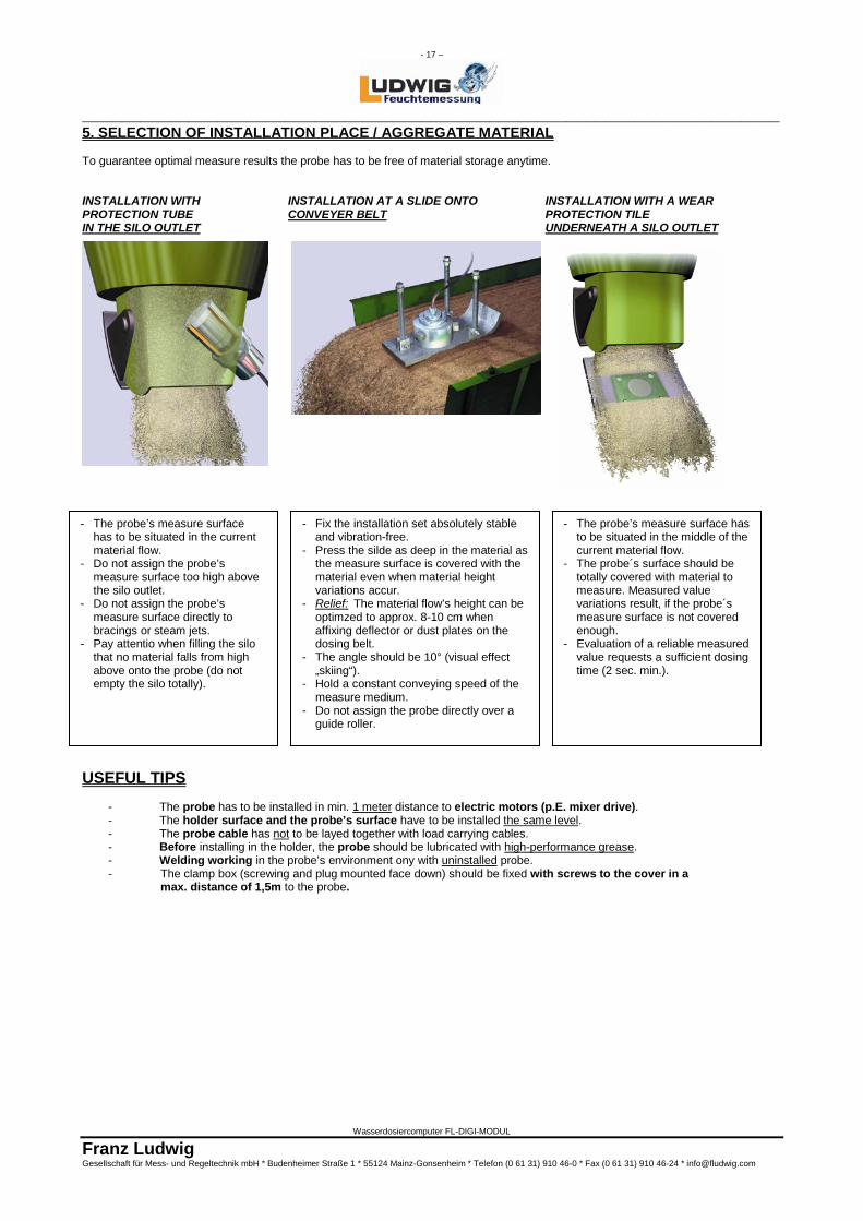
5. SELECTION OF INSTALLATION PLACE / AGGREGATE MATERIAL To guarantee optimal measure results the probe has to be free of material storage anytime. INSTALLATION WITH INSTALLATION AT A SLIDE ONTO INSTALLATION WITH A WEAR PROTECTION TUBE CONVEYER BELT PROTECTION TILE IN THE SILO OUTLET UNDERNEATH A SILO OUTLET
USEFUL TIPS
- The probe has to be installed in min. 1 meter distance to electric motors (p.E. mixer drive). - The holder surface and the probe’s surface have to be installed the same level. - The probe cable has not to be layed together with load carrying cables. - Before installing in the holder, the probe should be lubricated with high-performance grease. - Welding working in the probe’s environment ony with uninstalled probe. - The clamp box (screwing and plug mounted face down) should be fixed with screws to the cover in a
max. distance of 1,5m to the probe.
- The probe’s measure surface has to be situated in the current material flow. - Do not assign the probe’s measure surface too high above the silo outlet. - Do not assign the probe’s measure surface directly to bracings or steam jets. - Pay attentio when filling the silo that no material falls from high above onto the probe (do not empty the silo totally).
- Fix the installation set absolutely stable and vibration-free. - Press the silde as deep in the material as the measure surface is covered with the material even when material height variations accur. - Relief: The material flow’s height can be optimzed to approx. 8-10 cm when affixing deflector or dust plates on the dosing belt. - The angle should be 10° (visual effect „skiing“). - Hold a constant conveying speed of the measure medium. - Do not assign the probe directly over a guide roller.
- The probe’s measure surface has to be situated in the middle of the current material flow. - The probe´s surface should be totally covered with material to measure. Measured value variations result, if the probe´s measure surface is not covered enough. - Evaluation of a reliable measured value requests a sufficient dosing time (2 sec. min.).
- 18 –
________________________________________________________________________
Wasserdosiercomputer FL-DIGI-MODUL
Franz Ludwig Gesellschaft für Mess- und Regeltechnik mbH * Budenheimer Straße 1 * 55124 Mainz-Gonsenheim * Telefon (0 61 31) 910 46-0 * Fax (0 61 31) 910 46-24 * [email protected]
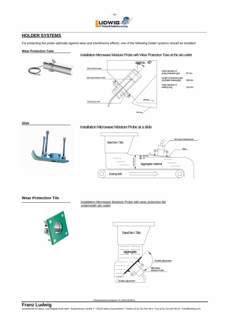
HOLDER SYSTEMS For protecting the probe optimally against wear and interference effects, one of the following holder systems should be installed: Wear Protection Tube
Slide
Wear Protection Tile Installation Microwave Moisture Probe with wear protection tile underneath silo outlet
Outer diameter ofprobe protection pipe: 87 mm Length of protection pipe(shortable individually): 300 mm
Outer diameter ofwelding ring: 124 mm
Wear protection pipe
Microwave Moisture Probe
Silo clap
openingFixing ring to weld
Installation Microwave Moisture Probe with Wear Protection Tube at the silo outlet
approx. 45°
Dosing belt
Aggregate material
Sand bin / Silo
Installation Microwave Moisture Probe at a slidem
in. 8
0 m
m
app. 20 mmapp. 10°
Microwave Moistureprobe
Slide
aggregate
Sand bin / Silo
MikrowaveMoisture Probe
Flexible adjustment!
Flexible adjustment!
- 19 –
________________________________________________________________________
Wasserdosiercomputer FL-DIGI-MODUL
Franz Ludwig Gesellschaft für Mess- und Regeltechnik mbH * Budenheimer Straße 1 * 55124 Mainz-Gonsenheim * Telefon (0 61 31) 910 46-0 * Fax (0 61 31) 910 46-24 * [email protected]
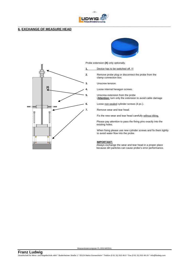
6. EXCHANGE OF MEASURE HEAD
Probe extension (X) only optionally. 1. Device has to be switched off. !!! 2. Remove probe plug or disconnect the probe from the clamp connection box. 3. Unscrew tension. 4. Loose internal hexagon screws. 5. Unscrew extension from the probe (Attention: turn only the extension to avoid cable damage 6. Loose non-sealed cylinder screws (4 pc.). 7. Remove wear and tear head. Fix the new wear and tear head carefully without tilting.
Please pay attention to pass the fixing pins exactly into the existing holes.
When fixing please use new cylinder screws and fix them tightly to avoid water flow into the probe. Sonde eindringt. IMPORTANT:
Always exchange the wear and tear head in a proper place because dirt particles can cause probe’s error performance.
(X)
- 20 –
________________________________________________________________________
Wasserdosiercomputer FL-DIGI-MODUL
Franz Ludwig Gesellschaft für Mess- und Regeltechnik mbH * Budenheimer Straße 1 * 55124 Mainz-Gonsenheim * Telefon (0 61 31) 910 46-0 * Fax (0 61 31) 910 46-24 * [email protected]
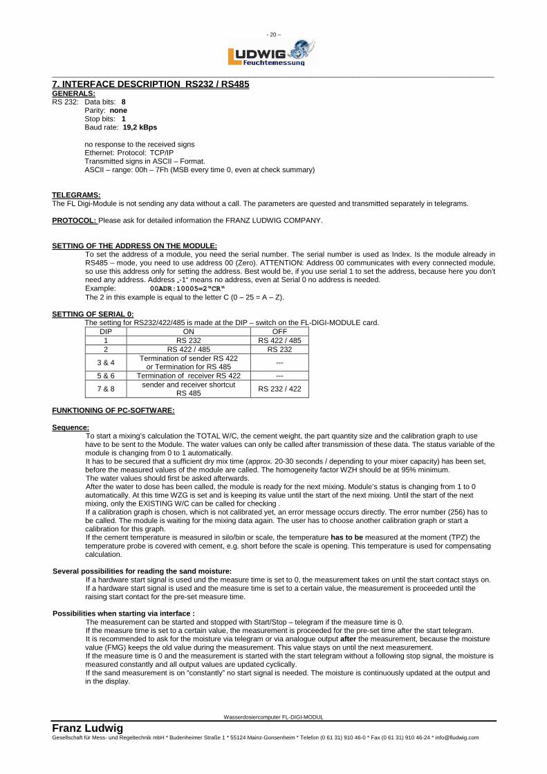
7. INTERFACE DESCRIPTION RS232 / RS485 GENERALS: RS 232: Data bits: 8
Parity: none Stop bits: 1 Baud rate: 19,2 kBps no response to the received signs Ethernet: Protocol: TCP/IP Transmitted signs in ASCII – Format. ASCII – range: 00h – 7Fh (MSB every time 0, even at check summary)
TELEGRAMS: The FL Digi-Module is not sending any data without a call. The parameters are quested and transmitted separately in telegrams. PROTOCOL: Please ask for detailed information the FRANZ LUDWIG COMPANY. SETTING OF THE ADDRESS ON THE MODULE:
To set the address of a module, you need the serial number. The serial number is used as Index. Is the module already in RS485 – mode, you need to use address 00 (Zero). ATTENTION: Address 00 communicates with every connected module, so use this address only for setting the address. Best would be, if you use serial 1 to set the address, because here you don’t need any address. Address „-1“ means no address, even at Serial 0 no address is needed. Example: 00ADR:10005=2“CR“ The 2 in this example is equal to the letter C (0 – 25 = A – Z).
SETTING OF SERIAL 0: The setting for RS232/422/485 is made at the DIP – switch on the FL-DIGI-MODULE card.
DIP ON OFF 1 RS 232 RS 422 / 485 2 RS 422 / 485 RS 232
3 & 4 Termination of sender RS 422 or Termination for RS 485 ---
5 & 6 Termination of receiver RS 422 ---
7 & 8 sender and receiver shortcut RS 485 RS 232 / 422
FUNKTIONING OF PC-SOFTWARE: Sequence:
To start a mixing’s calculation the TOTAL W/C, the cement weight, the part quantity size and the calibration graph to use have to be sent to the Module. The water values can only be called after transmission of these data. The status variable of the module is changing from 0 to 1 automatically. It has to be secured that a sufficient dry mix time (approx. 20-30 seconds / depending to your mixer capacity) has been set, before the measured values of the module are called. The homogeneity factor WZH should be at 95% minimum. The water values should first be asked afterwards. After the water to dose has been called, the module is ready for the next mixing. Module’s status is changing from 1 to 0 automatically. At this time WZG is set and is keeping its value until the start of the next mixing. Until the start of the next mixing, only the EXISTING W/C can be called for checking . If a calibration graph is chosen, which is not calibrated yet, an error message occurs directly. The error number (256) has to be called. The module is waiting for the mixing data again. The user has to choose another calibration graph or start a calibration for this graph. If the cement temperature is measured in silo/bin or scale, the temperature has to be measured at the moment (TPZ) the temperature probe is covered with cement, e.g. short before the scale is opening. This temperature is used for compensating calculation.
Several possibilities for reading the sand moisture: If a hardware start signal is used und the measure time is set to 0, the measurement takes on until the start contact stays on. If a hardware start signal is used and the measure time is set to a certain value, the measurement is proceeded until the raising start contact for the pre-set measure time.
Possibilities when starting via interface : The measurement can be started and stopped with Start/Stop – telegram if the measure time is 0. If the measure time is set to a certain value, the measurement is proceeded for the pre-set time after the start telegram. It is recommended to ask for the moisture via telegram or via analogue output after the measurement, because the moisture value (FMG) keeps the old value during the measurement. This value stays on until the next measurement. If the measure time is 0 and the measurement is started with the start telegram without a following stop signal, the moisture is measured constantly and all output values are updated cyclically. If the sand measurement is on “constantly” no start signal is needed. The moisture is continuously updated at the output and in the display.
- 21 –
________________________________________________________________________
Wasserdosiercomputer FL-DIGI-MODUL
Franz Ludwig Gesellschaft für Mess- und Regeltechnik mbH * Budenheimer Straße 1 * 55124 Mainz-Gonsenheim * Telefon (0 61 31) 910 46-0 * Fax (0 61 31) 910 46-24 * [email protected]
Calibration by control: First you need to start a regular batch. The control has to take care of dosing not the calculated, but the previously entered water amount. After dosing the water and a wet mix time of at least 50 sec., the control has to send the dosed water amount to the FL-DIGI-MODULE (TDW). The FL-DIGI-MODULE now calculates the values of the calibration graph. Are these values in a valid range, the module stores this values, else error No. 4 is set. The calculated values (if valid or not) can be read with EKSME and EKOME.
Calibration by PC-Software:
First the water to dose has to be set and the calibration has to initiated. Data to the module: 1. Next mixing is calibrated (KBN=1) 2. Additional water (ZGW) Now the module knows: 1. calculate and give out W/C-values with standard graph 2. not to transmit the evaluated water to dose but the additional water to the control 3. error message “5: too wet” is deactivated 4. status is set automatically to 2 If all mixing data are sent to the module (as the normal sequence), the status is changing its value to 3. As soon as the water to dose is called, the status is set to 4 automatically. The EXISTING-W/C of the dry material (WZG) has even to be called. After the dosing of the water you have to wait approx. 50 sec. and than call the EXISTING-W/C-value of the wet mixing (WZI). After that the calibration mode has to be set back to 0 manually (KBN=0). Herewith the status is set to 0 automatically. Now the graph values have to be calculated (here the parameter terms have been used): EKS = (ZGW / ZMI) / (IWZwet – IWZdry) EKO = IWZwet - WZS / EKS The steep has to be between 0,1 and 10 (usually between 0,5 and 3), the offset has to be between -0,5 and +0,5 (usually between 0 and 0,3). Both values have to be sent now with EKS and EKO to the module. Even EKEIN of this graph has to be set to 1 to get the graph valid and able to be used. The index shows the corresponding graph number. The graphs should even be able to be stored from the module, to be manually changed and then to be set again. Remark: Please pay attention to the chapter 1.7 Calibration Mixer.
Calibration sand: For calibration of the sand probe 6 values per graph are needed. They are corresponding to 3 value pairs form the measured quotient EKQ1…EKQ3 and corresponded moisture EKF1…EKF3. The pair values have to be raising up from 1 to 3. The index is also giving the calibration graph number. Example: Quotient 1 = 1.234 corresponds moisture 1 = 2,22% Quotient 2 = 2.468 corresponds moisture 2 = 4,44% Quotient 3 = 3.690 corresponds moisture 3 = 6,66% Remark: Please pay attention to the chapter 1.8 Calibration Aggregate Material.
- 22 –
________________________________________________________________________
Wasserdosiercomputer FL-DIGI-MODUL
Franz Ludwig Gesellschaft für Mess- und Regeltechnik mbH * Budenheimer Straße 1 * 55124 Mainz-Gonsenheim * Telefon (0 61 31) 910 46-0 * Fax (0 61 31) 910 46-24 * [email protected]
8. INTERFACE DESCRIPTION ETHERNET
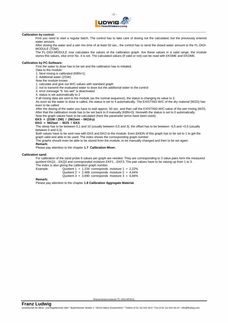
Ethernet Interface Setting Up For identification of the IP–Address the delivered „Device Installer“ is necessary to be installed. For installing this program, Microsoft DotNet Version 2.0 has to be installed in advance. Check first, if Microsoft DotNet 2.0 is installed on your PC. If not, install the delivered version 2.0 with ’dotnetfx.exe’. Follow the steps. Install now ‘Device Installer’ with ‘Setup.exe’ in the directory ‘Device Installer’ and follow the steps. Start now Device Installer and click the ‘Search’-Button:
All connected modules are now displayed. If the Sub Net Mask is not corresponding to your network the module is shown in red. To assign a new IP-Address to a module, click ‘Assign IP’. Choose ‘Assign a specific IP-Address’ and enter the new address. The Sub Net Mask is determined automatically. When clicking ‘Assign’ and ‘Finish’ the IP-Address is assigned. For setting of the ports, choose a module by opening all sub menus on the left side and open a Telenet Connection via port 9999 by choosing the tab Telnet Configuration on the right side and then clicking on Connect:
- 23 –
________________________________________________________________________
Wasserdosiercomputer FL-DIGI-MODUL
Franz Ludwig Gesellschaft für Mess- und Regeltechnik mbH * Budenheimer Straße 1 * 55124 Mainz-Gonsenheim * Telefon (0 61 31) 910 46-0 * Fax (0 61 31) 910 46-24 * [email protected]
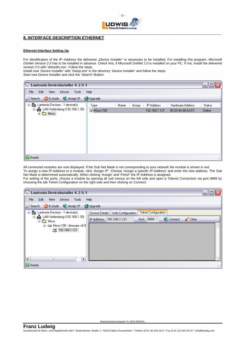
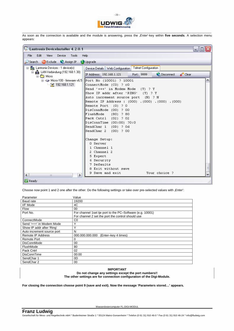
As soon as the connection is available and the module is answering, press the ‚Enter’-key within five seconds. A selection menu appears:
Choose now point 1 and 2 one after the other. Do the following settings or take over pre-selected values with ‚Enter’: Parameter Value Baud rate 19200 I/F Mode 4C Flow 00 Port No. For channel 1set tje port to the PC–Software (e.g. 10001)
For channel 2 set the port the control should use ConnectMode C0 Send ‘+++’ in Modem Mode Y Show IP addr after 'Ring’ Y Auto increment source port N Remote IP Address 000.000.000.000 (Enter–key 4 times) Remote Port 0 DisConnMode 00 FlushMode 80 Pack Cntrl 02 DisConnTime 00:00 SendChar 1 0D SendChar 2 00
IMPORTANT Do not change any settings except the port numbers!!
The other settings are for connection configuration of the Digi-Module.
For closing the connection choose point 9 (save and exit). Now the message ‘Parameters stored…’ appears.
- 24 –
________________________________________________________________________
Wasserdosiercomputer FL-DIGI-MODUL
Franz Ludwig Gesellschaft für Mess- und Regeltechnik mbH * Budenheimer Straße 1 * 55124 Mainz-Gonsenheim * Telefon (0 61 31) 910 46-0 * Fax (0 61 31) 910 46-24 * [email protected]
Go on with the next module by choosing it on the left side, until all modules are configurated and close the ‘Device Installer’.
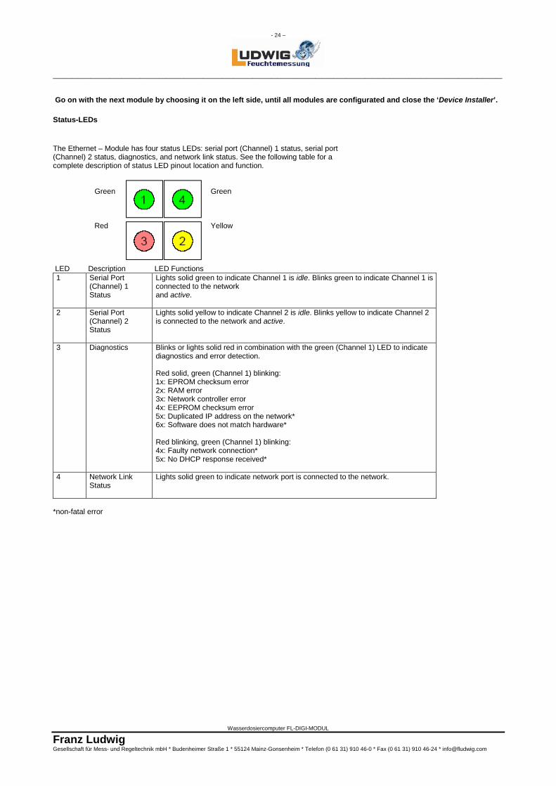
Status-LEDs The Ethernet – Module has four status LEDs: serial port (Channel) 1 status, serial port (Channel) 2 status, diagnostics, and network link status. See the following table for a complete description of status LED pinout location and function. Green Green
Red Yellow
LED Description LED Functions 1 Serial Port
(Channel) 1 Status
Lights solid green to indicate Channel 1 is idle. Blinks green to indicate Channel 1 is connected to the network and active.
2 Serial Port (Channel) 2 Status
Lights solid yellow to indicate Channel 2 is idle. Blinks yellow to indicate Channel 2 is connected to the network and active.
3 Diagnostics Blinks or lights solid red in combination with the green (Channel 1) LED to indicate diagnostics and error detection. Red solid, green (Channel 1) blinking: 1x: EPROM checksum error 2x: RAM error 3x: Network controller error 4x: EEPROM checksum error 5x: Duplicated IP address on the network* 6x: Software does not match hardware* Red blinking, green (Channel 1) blinking: 4x: Faulty network connection* 5x: No DHCP response received*
4 Network Link Status
Lights solid green to indicate network port is connected to the network.
LED Description Location LED Functions *non-fatal error
- 25 –
________________________________________________________________________
Wasserdosiercomputer FL-DIGI-MODUL
Franz Ludwig Gesellschaft für Mess- und Regeltechnik mbH * Budenheimer Straße 1 * 55124 Mainz-Gonsenheim * Telefon (0 61 31) 910 46-0 * Fax (0 61 31) 910 46-24 * [email protected]
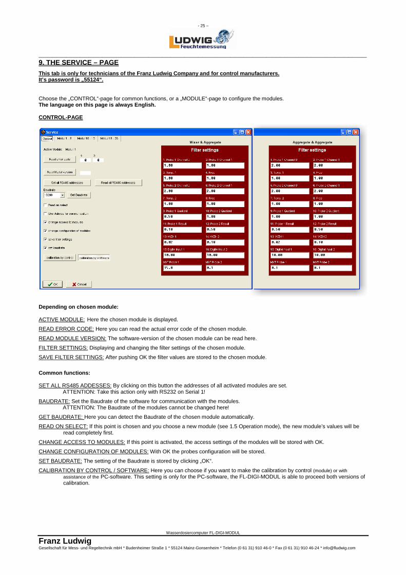
9. THE SERVICE – PAGE This tab is only for technicians of the Franz Ludwig Company and for control manufacturers. It’s password is „55124“. Choose the „CONTROL“-page for common functions, or a „MODULE“-page to configure the modules. The language on this page is always English. CONTROL-PAGE
Depending on chosen module: ACTIVE MODULE: Here the chosen module is displayed.
READ ERROR CODE: Here you can read the actual error code of the chosen module.
READ MODULE VERSION: The software-version of the chosen module can be read here.
FILTER SETTINGS: Displaying and changing the filter settings of the chosen module.
SAVE FILTER SETTINGS: After pushing OK the filter values are stored to the chosen module.
Common functions: SET ALL RS485 ADDESSES: By clicking on this button the addresses of all activated modules are set. ATTENTION: Take this action only with RS232 on Serial 1!
BAUDRATE: Set the Baudrate of the software for communication with the modules. ATTENTION: The Baudrate of the modules cannot be changed here!
GET BAUDRATE: Here you can detect the Baudrate of the chosen module automatically.
READ ON SELECT: If this point is chosen and you choose a new module (see 1.5 Operation mode), the new module’s values will be read completely first.
CHANGE ACCESS TO MODULES: If this point is activated, the access settings of the modules will be stored with OK.
CHANGE CONFIGURATION OF MODULES: With OK the probes configuration will be stored.
SET BAUDRATE: The setting of the Baudrate is stored by clicking „OK“.
CALIBRATION BY CONTROL / SOFTWARE: Here you can choose if you want to make the calibration by control (module) or with assistance of the PC-software. This setting is only for the PC-software, the FL-DIGI-MODUL is able to proceed both versions of calibration.
- 26 –
________________________________________________________________________
Wasserdosiercomputer FL-DIGI-MODUL
Franz Ludwig Gesellschaft für Mess- und Regeltechnik mbH * Budenheimer Straße 1 * 55124 Mainz-Gonsenheim * Telefon (0 61 31) 910 46-0 * Fax (0 61 31) 910 46-24 * [email protected]
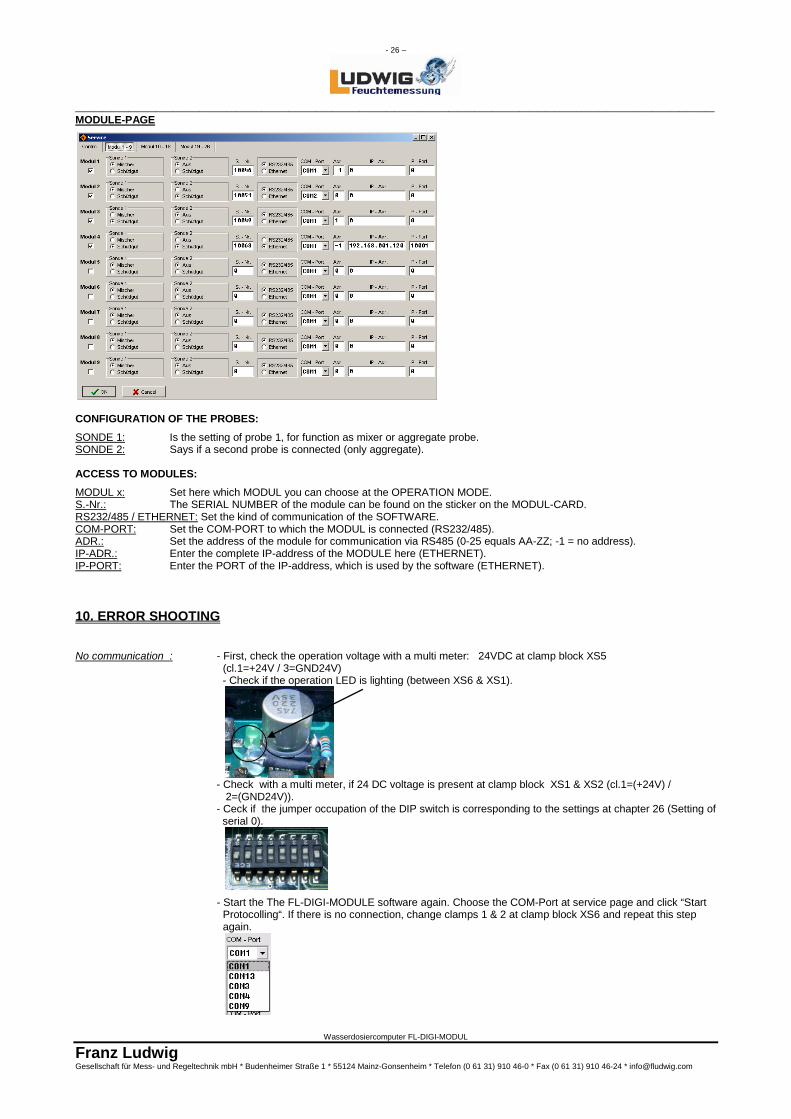
MODULE-PAGE
CONFIGURATION OF THE PROBES: SONDE 1: Is the setting of probe 1, for function as mixer or aggregate probe. SONDE 2: Says if a second probe is connected (only aggregate). ACCESS TO MODULES: MODUL x: Set here which MODUL you can choose at the OPERATION MODE. S.-Nr.: The SERIAL NUMBER of the module can be found on the sticker on the MODUL-CARD. RS232/485 / ETHERNET: Set the kind of communication of the SOFTWARE. COM-PORT: Set the COM-PORT to which the MODUL is connected (RS232/485). ADR.: Set the address of the module for communication via RS485 (0-25 equals AA-ZZ; -1 = no address). IP-ADR.: Enter the complete IP-address of the MODULE here (ETHERNET). IP-PORT: Enter the PORT of the IP-address, which is used by the software (ETHERNET). 10. ERROR SHOOTING
No communication : - First, check the operation voltage with a multi meter: 24VDC at clamp block XS5 (cl.1=+24V / 3=GND24V)
- Check if the operation LED is lighting (between XS6 & XS1).
- Check with a multi meter, if 24 DC voltage is present at clamp block XS1 & XS2 (cl.1=(+24V) / 2=(GND24V)). - Ceck if the jumper occupation of the DIP switch is corresponding to the settings at chapter 26 (Setting of serial 0).
- Start the The FL-DIGI-MODULE software again. Choose the COM-Port at service page and click “Start Protocolling“. If there is no connection, change clamps 1 & 2 at clamp block XS6 and repeat this step again.