Embed Size (px)
Citation preview
A product of SEGGER Microconroller GmbH & Co. KG
www.segger.com
FlasherUser Guide
Software Version V6.14Manual Rev. 0
Document: UM08022
Date: July 21, 2017
2
Disclaimer
Specifications written in this document are believed to be accurate, but are not guar-anteed to be entirely free of error. The information in this manual is subject tochange for functional or performance improvements without notice. Please make sureyour manual is the latest edition. While the information herein is assumed to beaccurate, SEGGER Microcontroller GmbH & Co. KG (the manufacturer) assumes noresponsibility for any errors or omissions. The manufacturer makes and you receiveno warranties or conditions, express, implied, statutory or in any communication withyou. The manufacturer specifically disclaims any implied warranty of merchantabilityor fitness for a particular purpose.
Copyright notice
You may not extract portions of this manual or modify the PDF file in any way withoutthe prior written permission of the manufacturer. The software described in this doc-ument is furnished under a license and may only be used or copied in accordancewith the terms of such a license.
© 2016 SEGGER Microcontroller GmbH & Co. KG, Hilden / Germany
Trademarks
Names mentioned in this manual may be trademarks of their respective companies.
Brand and product names are trademarks or registered trademarks of their respec-tive holders.
Contact address
SEGGER Microcontroller GmbH & Co. KG
In den Weiden 11D-40721 Hilden
Germany
Tel.+49 2103-2878-0Fax.+49 2103-2878-28Email: [email protected]: http://www.segger.com
Revisions
This manual describes the Flasher device.
For further information on topics or routines not yet specified, please contact us.
Revision Date By Explanation
V6.10a Rev. 0 160922 EL Chapter "Introduction" * Section "Flasher Portable" updated.
V6.00 Rev. 0 160715 NG Chapter "Working with Flasher" * Section "Batch Programming" added.
V5.12e Rev. 0 160511 NG
Chapter "Working with Flasher" * Section "Setting up Flasher for stand-alone mode" moved. * Section "Preparing for stand-alone operation manually" added.
V5.02f Rev. 0 151023 RHChapter "Remote control" * Section "General usage" addded.
V5.02e Rev. 0 151021 EL Chapter "Introduction" * Section "Specifications" updated for all models.
Flasher User Guide (UM08022) © 2004-2016 SEGGER Microcontroller GmbH & Co. KG
3
V5.02f Rev. 0 151014 RHChapter "Working with Flasher" * Section "Programming multiple targets" addded.
V4.50c Rev. 0 150611 ELChapter "Working with Flasher" * Section "Programming multiple targets in parallel" addded.
V4.98 Rev. 0 150205 AG
Chapter "Working with Flasher" * Section "Authorized flashing" added. * Section "Limiting the number of programming cycles" added. * Section "Operating Modes" updated
V4.86 Rev. 0 140610 AG Chapter "Working with Flasher" * Section "Newline encoding" added.
V4.80 Rev. 1 131220 AG Chapter "Working with Flasher" * Section "Multiple File Support" updated.
V4.80 Rev. 0 131031 ELChapter "Remote control" * Section "Commands to Flasher" updated. #FCRC command added.
V4.78 Rev. 0 130917 AG
Chapter "Introduction" * Section "Features of Flasher Portable" added.Chapter "Working with Flasher" * Section "Flasher Portable" added. * Section "Multiple File Support" updated.
V4.72 Rev. 0 130612 EL Chapter "Working with Flasher" * Section "Patch file support" added.
V4.64a Rev. 0 130226 EL Chapter "Working with Flasher" * Section "LED status indicators" updated.
V4.63a Rev. 0 130131 ELChapter "Remote Control" * Section "ASCII command interface" Chapter "ASCII interface via Telnet" added.
V4.62 Rev. 0 130125 EL Flasher ARM, Flasher RX and Flasher PPC manual have been combined.
V5.02 Rev 0 150807 RE New commands #FLIST and #MKDIR in ASCII com-mand interface
Revision Date By Explanation
Flasher User Guide (UM08022) © 2004-2016 SEGGER Microcontroller GmbH & Co. KG

4
Flasher User Guide (UM08022) © 2004-2016 SEGGER Microcontroller GmbH & Co. KG
5
About this document
This document describes the Flasher family (Flasher ARM, Flasher RX and FlasherPPC). It provides an overview about the major features of the Flasher, gives somebackground information about JTAG and describes Flasher related software packagesavailable from Segger. Finally, the chapter Support and FAQs on page 89 helps totroubleshoot common problems.
For simplicity, we will refer to Flasher ARM/RX/PPC as Flasher in this manual.
Typographic conventions
This manual uses the following typographic conventions:
Style Used for
Body Body text.
KeywordText that you enter at the command-prompt or that appears on the display (that is system functions, file- or pathnames).
Reference Reference to chapters, tables and figures or other documents.
GUIElement Buttons, dialog boxes, menu names, menu commands.
Table 1.1: Typographic conventions
Flasher User Guide (UM08022) © 2004-2016 SEGGER Microcontroller GmbH & Co. KG
6
EMBEDDED SOFTWARE(Middleware)
emWinGraphics software and GUIemWin is designed to provide an effi-cient, processor- and display control-ler-independent graphical user interface (GUI) for any application that operates with a graphical display. Starterkits, eval- and trial-versions are available.
embOSReal Time Operating SystemembOS is an RTOS designed to offer the benefits of a complete multitasking system for hard real time applications with minimal resources. The profiling PC tool embOSView is included.
emFileFile systememFile is an embedded file system with FAT12, FAT16 and FAT32 support. emFile has been optimized for mini-mum memory consumption in RAM and ROM while maintaining high speed. Various Device drivers, e.g. for NAND and NOR flashes, SD/MMC and Com-pactFlash cards, are available.
emUSBUSB device stackA USB stack designed to work on any embedded system with a USB client controller. Bulk communication and most standard device classes are sup-ported.
SEGGER TOOLS
Flasher Flash programmerFlash Programming tool primarily for microcon-trollers.
J-LinkJTAG emulator for ARM coresUSB driven JTAG interface for ARM cores.
J-TraceJTAG emulator with traceUSB driven JTAG interface for ARM cores with Trace memory. supporting the ARM ETM (Embed-ded Trace Macrocell).
J-Link / J-Trace Related SoftwareAdd-on software to be used with SEGGER�s indus-try standard JTAG emulator, this includes flash programming software and flash breakpoints.
SEGGER Microcontroller GmbH & Co. KG developsand distributes software development tools and ANSIC software components (middleware) for embeddedsystems in several industries such as telecom, medi-cal technology, consumer electronics, automotiveindustry and industrial automation.
SEGGER�s intention is to cut software development-time for embedded applications by offering compact flexible and easy to use middleware,allowing developers to concentrate on their application.
Our most popular products are emWin, a universal graphic software package for embed-ded applications, and embOS, a small yet efficient real-time kernel. emWin, writtenentirely in ANSI C, can easily be used on any CPU and most any display. It is comple-mented by the available PC tools: Bitmap Converter, Font Converter, Simulator andViewer. embOS supports most 8/16/32-bit CPUs. Its small memory footprint makes itsuitable for single-chip applications.
Apart from its main focus on software tools, SEGGER develops and produces programmingtools for flash microcontrollers, as well as J-Link, a JTAG emulator to assist in develop-ment, debugging and production, which has rapidly become the industry standard fordebug access to ARM cores.
Corporate Office:http://www.segger.com
United States Office:http://www.segger-us.com
Flasher User Guide (UM08022) © 2004-2016 SEGGER Microcontroller GmbH & Co. KG
7
Table of Contents
1 Introduction ....................................................................................................................11
1.1 Flasher overview .....................................................................................121.1.1 Features of Flasher ARM/PPC/RX................................................................121.1.2 Features of Flasher Portable ......................................................................131.1.3 Working environment...............................................................................131.2 Specifications..........................................................................................141.2.1 Specifications for Flasher ARM ...................................................................141.2.2 Specifications for Flasher RX .....................................................................161.2.3 Specifications for Flasher PPC....................................................................181.2.4 Specifications for Flasher Portable..............................................................20
2 Working with Flasher .....................................................................................................23
2.1 Flasher Portable ......................................................................................242.1.1 Housing & Buttons ...................................................................................252.2 Setting up the IP interface ........................................................................272.2.1 Connecting the first time ..........................................................................272.3 Operating modes .....................................................................................282.3.1 J-Link mode............................................................................................282.3.2 Stand-alone mode ...................................................................................292.3.3 MSD mode..............................................................................................312.4 Setting up Flasher for stand-alone mode.....................................................322.4.1 Preparing for stand-alone operation manually..............................................352.5 Universal Flash Loader mode.....................................................................372.5.1 Preparing manually ..................................................................................372.5.2 Preparing using the PC utility ....................................................................402.6 Multiple File Support ................................................................................412.6.1 Flasher Portable specifics .........................................................................412.6.2 Example.................................................................................................422.7 Programming multiple targets ...................................................................432.7.1 Programming multiple targets with J-Flash..................................................432.8 Batch Programming in stand-alone mode ....................................................442.8.1 Flasher Portable specifics ..........................................................................442.8.2 Examples ...............................................................................................452.9 Serial number programming......................................................................462.9.1 Serial number settings .............................................................................462.9.2 Serial number file ....................................................................................472.9.3 Serial number list file ...............................................................................472.9.4 Programming process...............................................................................482.9.5 Downloading serial number files to Flasher..................................................492.9.6 Sample setup..........................................................................................492.10 Patch file support.....................................................................................512.11 Limiting the number of programming cycles ................................................522.11.1 Changed fail/error LED indicator behavior ...................................................522.11.2 Required Flasher hardware version for Cntdown.txt support ..........................522.12 Authorized flashing ..................................................................................532.12.1 Creating / Adding the secure area..............................................................532.12.2 Moving files to the secure area ..................................................................542.12.3 Considerations to be taken when using the secure area ................................552.12.4 Required Flasher hardware version ............................................................552.13 Target interfaces .....................................................................................562.14 Supported microcontrollers .......................................................................57
Flasher User Guide (UM08022) © 2004-2016 SEGGER Microcontroller GmbH & Co. KG
8
2.14.1 Flasher .................................................................................................. 572.15 Support of external flashes....................................................................... 582.15.1 Flasher ARM ........................................................................................... 582.15.2 Flasher RX.............................................................................................. 582.15.3 Flasher PPC ............................................................................................ 582.16 Supported cores...................................................................................... 592.16.1 Flasher ARM ........................................................................................... 592.16.2 Flasher RX.............................................................................................. 592.16.3 Flasher PPC ............................................................................................ 592.17 Newline encoding .................................................................................... 602.18 Programming multiple targets in parallel .................................................... 61
3 Remote control...............................................................................................................63
3.1 Overview ............................................................................................... 643.2 Handshake control .................................................................................. 653.3 ASCII command interface......................................................................... 663.3.1 Introduction ........................................................................................... 663.3.2 General command and reply message format.............................................. 663.3.3 General usage ........................................................................................ 663.3.4 Settings for ASCII interface via RS232 ....................................................... 663.3.5 Settings for ASCII interface via Telnet........................................................ 663.3.6 Commands to Flasher .............................................................................. 673.3.7 Reply from Flasher .................................................................................. 72
4 Performance ..................................................................................................................75
4.1 Performance of MCUs with internal flash memory ........................................ 764.1.1 Flasher ARM ........................................................................................... 764.1.2 Flasher RX.............................................................................................. 764.1.3 Flasher PPC ............................................................................................ 76
5 Hardware .......................................................................................................................77
5.1 Flasher ARM 20-pin JTAG/SWD Connector .................................................. 785.1.1 Pinout JTAG............................................................................................ 785.1.2 Pinout SWD............................................................................................ 795.1.3 Target power supply ................................................................................ 795.2 Flasher RX 14-pin connector ..................................................................... 815.2.1 Target power supply ................................................................................ 815.3 Flasher PPC 14-pin connector.................................................................... 835.4 Target board design ................................................................................ 845.4.1 Pull-up/pull-down resistors ....................................................................... 845.4.2 RESET, nTRST ........................................................................................ 845.5 Adapters ................................................................................................ 855.5.1 JTAG Isolator.......................................................................................... 855.5.2 J-Link Needle Adapter .............................................................................. 865.6 How to determine the hardware version ..................................................... 87
6 Support and FAQs .........................................................................................................89
6.1 Contacting support .................................................................................. 906.2 Frequently Asked Questions...................................................................... 91
7 Background information .................................................................................................93
7.1 Flash programming ................................................................................. 947.1.1 How does flash programming via Flasher work?........................................... 947.1.2 Data download to RAM............................................................................. 947.1.3 Available options for flash programming ..................................................... 947.1.4 How does the universal flash programming work?........................................ 94
8 Glossary.........................................................................................................................95
Flasher User Guide (UM08022) © 2004-2016 SEGGER Microcontroller GmbH & Co. KG
9
9 Literature and references...............................................................................................99
Flasher User Guide (UM08022) © 2004-2016 SEGGER Microcontroller GmbH & Co. KG

10
Flasher User Guide (UM08022) © 2004-2016 SEGGER Microcontroller GmbH & Co. KG
11
Chapter 1
Introduction
This chapter gives a short overview about the different models of the Flasher familyand their features.
Flasher User Guide (UM08022) © 2004-2016 SEGGER Microcontroller GmbH & Co. KG
12 CHAPTER 1 Introduction
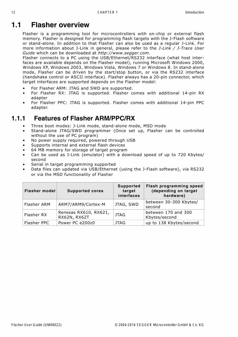
1.1 Flasher overviewFlasher is a programming tool for microcontrollers with on-chip or external flashmemory. Flasher is designed for programming flash targets with the J-Flash softwareor stand-alone. In addition to that Flasher can also be used as a regular J-Link. Formore information about J-Link in general, please refer to the J-Link / J-Trace UserGuide which can be downloaded at http://www.segger.com.Flasher connects to a PC using the USB/Ethernet/RS232 interface (what host inter-faces are available depends on the Flasher model), running Microsoft Windows 2000,Windows XP, Windows 2003, Windows Vista, Windows 7 or Windows 8. In stand-alonemode, Flasher can be driven by the start/stop button, or via the RS232 interface(handshake control or ASCII interface). Flasher always has a 20-pin connector, whichtarget interfaces are supported depends on the Flasher model:
� For Flasher ARM: JTAG and SWD are supported.� For Flasher RX: JTAG is supported. Flasher comes with additional 14-pin RX
adapter� For Flasher PPC: JTAG is supported. Flasher comes with additional 14-pin PPC
adapter.
1.1.1 Features of Flasher ARM/PPC/RX� Three boot modes: J-Link mode, stand-alone mode, MSD mode� Stand-alone JTAG/SWD programmer (Once set up, Flasher can be controlled
without the use of PC program)� No power supply required, powered through USB� Supports internal and external flash devices � 64 MB memory for storage of target program� Can be used as J-Link (emulator) with a download speed of up to 720 Kbytes/
second� Serial in target programming supported� Data files can updated via USB/Ethernet (using the J-Flash software), via RS232
or via the MSD functionality of Flasher
Flasher model Supported coresSupported
target interfaces
Flash programming speed(depending on target
hardware)
Flasher ARM ARM7/ARM9/Cortex-M JTAG, SWD between 30-300 Kbytes/second
Flasher RX Renesas RX610, RX621, RX62N, RX62T JTAG between 170 and 300
Kbytes/secondFlasher PPC Power PC e200z0 JTAG up to 138 Kbytes/second
Flasher User Guide (UM08022) © 2004-2016 SEGGER Microcontroller GmbH & Co. KG
13
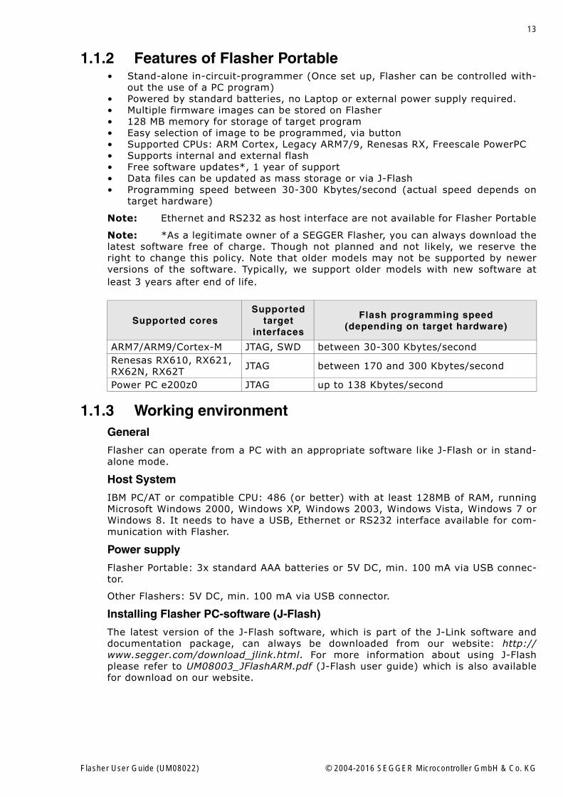
1.1.2 Features of Flasher Portable� Stand-alone in-circuit-programmer (Once set up, Flasher can be controlled with-
out the use of a PC program)� Powered by standard batteries, no Laptop or external power supply required.� Multiple firmware images can be stored on Flasher� 128 MB memory for storage of target program� Easy selection of image to be programmed, via button� Supported CPUs: ARM Cortex, Legacy ARM7/9, Renesas RX, Freescale PowerPC� Supports internal and external flash� Free software updates*, 1 year of support� Data files can be updated as mass storage or via J-Flash� Programming speed between 30-300 Kbytes/second (actual speed depends on
target hardware)
Note: Ethernet and RS232 as host interface are not available for Flasher Portable
Note: *As a legitimate owner of a SEGGER Flasher, you can always download thelatest software free of charge. Though not planned and not likely, we reserve theright to change this policy. Note that older models may not be supported by newerversions of the software. Typically, we support older models with new software atleast 3 years after end of life.
1.1.3 Working environmentGeneral
Flasher can operate from a PC with an appropriate software like J-Flash or in stand-alone mode.
Host System
IBM PC/AT or compatible CPU: 486 (or better) with at least 128MB of RAM, runningMicrosoft Windows 2000, Windows XP, Windows 2003, Windows Vista, Windows 7 orWindows 8. It needs to have a USB, Ethernet or RS232 interface available for com-munication with Flasher.
Power supply
Flasher Portable: 3x standard AAA batteries or 5V DC, min. 100 mA via USB connec-tor.
Other Flashers: 5V DC, min. 100 mA via USB connector.
Installing Flasher PC-software (J-Flash)
The latest version of the J-Flash software, which is part of the J-Link software anddocumentation package, can always be downloaded from our website: http://www.segger.com/download_jlink.html. For more information about using J-Flashplease refer to UM08003_JFlashARM.pdf (J-Flash user guide) which is also availablefor download on our website.
Supported coresSupported
target interfaces
Flash programming speed(depending on target hardware)
ARM7/ARM9/Cortex-M JTAG, SWD between 30-300 Kbytes/secondRenesas RX610, RX621, RX62N, RX62T JTAG between 170 and 300 Kbytes/second
Power PC e200z0 JTAG up to 138 Kbytes/second
Flasher User Guide (UM08022) © 2004-2016 SEGGER Microcontroller GmbH & Co. KG
14 CHAPTER 1 Introduction
1.2 Specifications
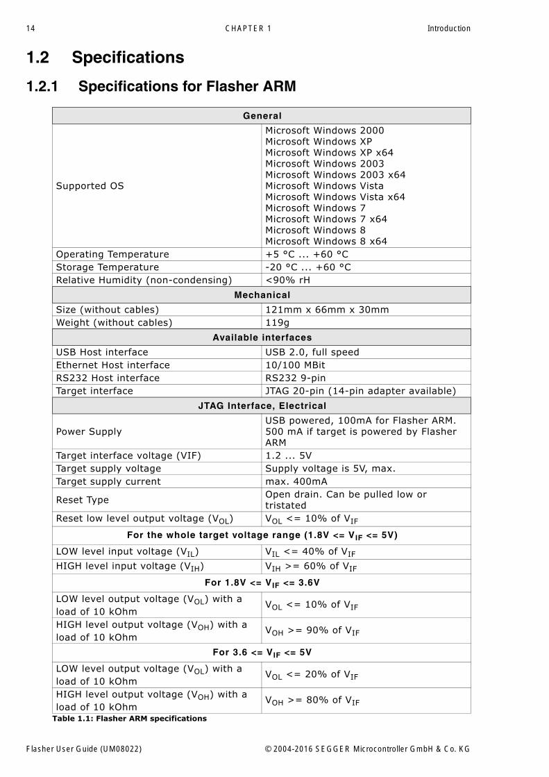
1.2.1 Specifications for Flasher ARM
General
Supported OS
Microsoft Windows 2000Microsoft Windows XPMicrosoft Windows XP x64Microsoft Windows 2003Microsoft Windows 2003 x64Microsoft Windows VistaMicrosoft Windows Vista x64Microsoft Windows 7Microsoft Windows 7 x64Microsoft Windows 8Microsoft Windows 8 x64
Operating Temperature +5 °C ... +60 °CStorage Temperature -20 °C ... +60 °CRelative Humidity (non-condensing) <90% rH
Mechanical
Size (without cables) 121mm x 66mm x 30mmWeight (without cables) 119g
Available interfaces
USB Host interface USB 2.0, full speedEthernet Host interface 10/100 MBitRS232 Host interface RS232 9-pinTarget interface JTAG 20-pin (14-pin adapter available)
JTAG Interface, Electrical
Power SupplyUSB powered, 100mA for Flasher ARM. 500 mA if target is powered by Flasher ARM
Target interface voltage (VIF) 1.2 ... 5VTarget supply voltage Supply voltage is 5V, max.Target supply current max. 400mA
Reset Type Open drain. Can be pulled low or tristated
Reset low level output voltage (VOL) VOL <= 10% of VIF
For the whole target voltage range (1.8V <= VIF <= 5V)
LOW level input voltage (VIL) VIL <= 40% of VIF
HIGH level input voltage (VIH) VIH >= 60% of VIF
For 1.8V <= VIF <= 3.6V
LOW level output voltage (VOL) with a load of 10 kOhm
VOL <= 10% of VIF
HIGH level output voltage (VOH) with a load of 10 kOhm
VOH >= 90% of VIF
For 3.6 <= VIF <= 5V
LOW level output voltage (VOL) with a load of 10 kOhm
VOL <= 20% of VIF
HIGH level output voltage (VOH) with a load of 10 kOhm
VOH >= 80% of VIF
Table 1.1: Flasher ARM specifications
Flasher User Guide (UM08022) © 2004-2016 SEGGER Microcontroller GmbH & Co. KG
15
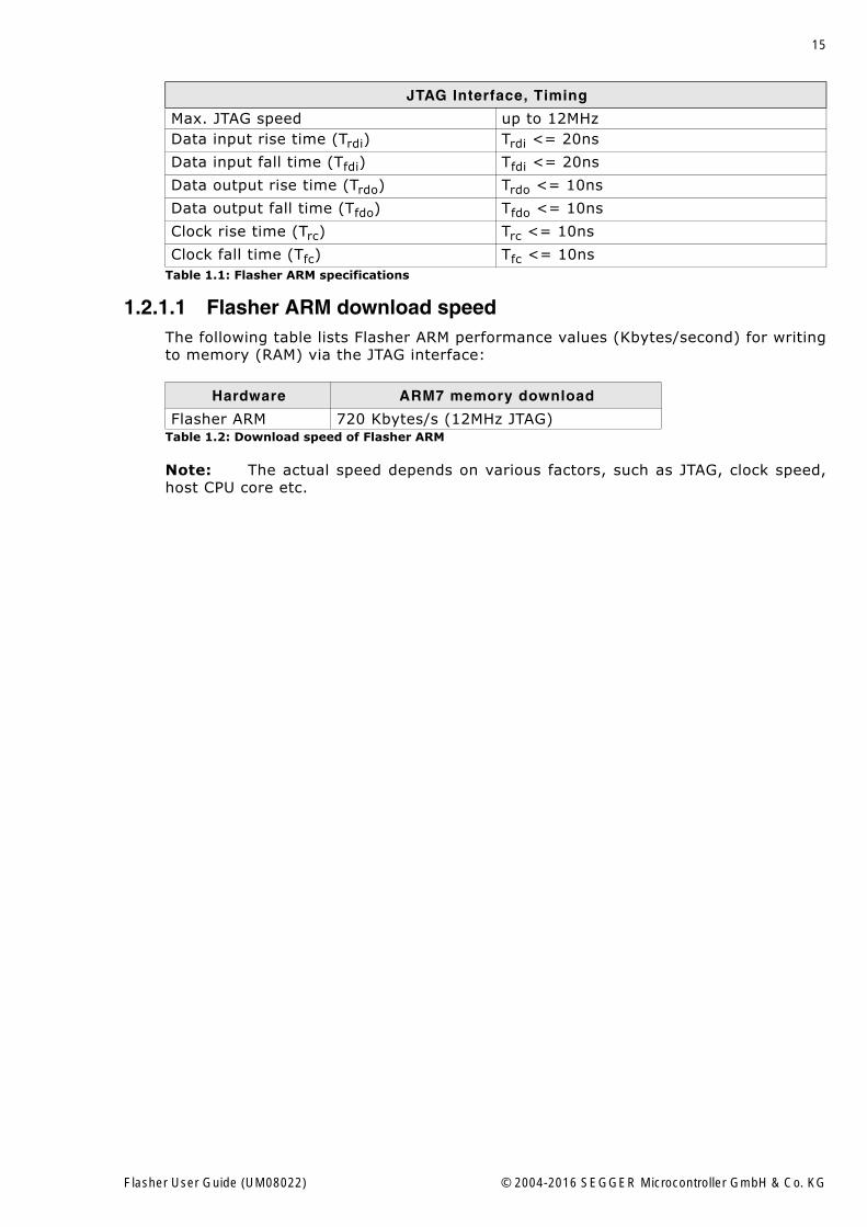
1.2.1.1 Flasher ARM download speedThe following table lists Flasher ARM performance values (Kbytes/second) for writingto memory (RAM) via the JTAG interface:
Note: The actual speed depends on various factors, such as JTAG, clock speed,host CPU core etc.
JTAG Interface, Timing
Max. JTAG speed up to 12MHzData input rise time (Trdi) Trdi <= 20ns
Data input fall time (Tfdi) Tfdi <= 20ns
Data output rise time (Trdo) Trdo <= 10ns
Data output fall time (Tfdo) Tfdo <= 10ns
Clock rise time (Trc) Trc <= 10ns
Clock fall time (Tfc) Tfc <= 10ns
Hardware ARM7 memory download
Flasher ARM 720 Kbytes/s (12MHz JTAG)Table 1.2: Download speed of Flasher ARM
Table 1.1: Flasher ARM specifications
Flasher User Guide (UM08022) © 2004-2016 SEGGER Microcontroller GmbH & Co. KG
16 CHAPTER 1 Introduction
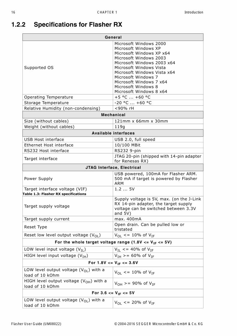
1.2.2 Specifications for Flasher RX
General
Supported OS
Microsoft Windows 2000Microsoft Windows XPMicrosoft Windows XP x64Microsoft Windows 2003Microsoft Windows 2003 x64Microsoft Windows VistaMicrosoft Windows Vista x64Microsoft Windows 7Microsoft Windows 7 x64Microsoft Windows 8Microsoft Windows 8 x64
Operating Temperature +5 °C ... +60 °CStorage Temperature -20 °C ... +60 °CRelative Humidity (non-condensing) <90% rH
Mechanical
Size (without cables) 121mm x 66mm x 30mmWeight (without cables) 119g
Available interfaces
USB Host interface USB 2.0, full speedEthernet Host interface 10/100 MBitRS232 Host interface RS232 9-pin
Target interface JTAG 20-pin (shipped with 14-pin adapter for Renesas RX)
JTAG Interface, Electrical
Power SupplyUSB powered, 100mA for Flasher ARM. 500 mA if target is powered by Flasher ARM
Target interface voltage (VIF) 1.2 ... 5V
Target supply voltage
Supply voltage is 5V, max. (on the J-Link RX 14-pin adapter, the target supply voltage can be switched between 3.3V and 5V)
Target supply current max. 400mA
Reset Type Open drain. Can be pulled low or tristated
Reset low level output voltage (VOL) VOL <= 10% of VIF
For the whole target voltage range (1.8V <= VIF <= 5V)
LOW level input voltage (VIL) VIL <= 40% of VIF
HIGH level input voltage (VIH) VIH >= 60% of VIF
For 1.8V <= VIF <= 3.6V
LOW level output voltage (VOL) with a load of 10 kOhm
VOL <= 10% of VIF
HIGH level output voltage (VOH) with a load of 10 kOhm
VOH >= 90% of VIF
For 3.6 <= VIF <= 5V
LOW level output voltage (VOL) with a load of 10 kOhm
VOL <= 20% of VIF
Table 1.3: Flasher RX specifications
Flasher User Guide (UM08022) © 2004-2016 SEGGER Microcontroller GmbH & Co. KG
17
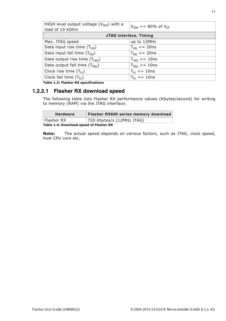
1.2.2.1 Flasher RX download speedThe following table lists Flasher RX performance values (Kbytes/second) for writingto memory (RAM) via the JTAG interface:
Note: The actual speed depends on various factors, such as JTAG, clock speed,host CPU core etc.
HIGH level output voltage (VOH) with a load of 10 kOhm
VOH >= 80% of VIF
JTAG Interface, Timing
Max. JTAG speed up to 12MHzData input rise time (Trdi) Trdi <= 20ns
Data input fall time (Tfdi) Tfdi <= 20ns
Data output rise time (Trdo) Trdo <= 10ns
Data output fall time (Tfdo) Tfdo <= 10ns
Clock rise time (Trc) Trc <= 10ns
Clock fall time (Tfc) Tfc <= 10ns
Hardware Flasher RX600 series memory download
Flasher RX 720 Kbytes/s (12MHz JTAG)Table 1.4: Download speed of Flasher RX
Table 1.3: Flasher RX specifications
Flasher User Guide (UM08022) © 2004-2016 SEGGER Microcontroller GmbH & Co. KG
18 CHAPTER 1 Introduction
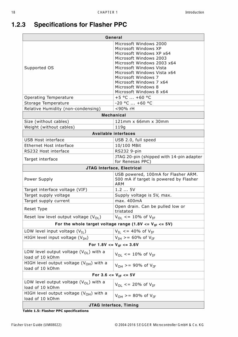
1.2.3 Specifications for Flasher PPC
General
Supported OS
Microsoft Windows 2000Microsoft Windows XPMicrosoft Windows XP x64Microsoft Windows 2003Microsoft Windows 2003 x64Microsoft Windows VistaMicrosoft Windows Vista x64Microsoft Windows 7Microsoft Windows 7 x64Microsoft Windows 8Microsoft Windows 8 x64
Operating Temperature +5 °C ... +60 °CStorage Temperature -20 °C ... +60 °CRelative Humidity (non-condensing) <90% rH
Mechanical
Size (without cables) 121mm x 66mm x 30mmWeight (without cables) 119g
Available interfaces
USB Host interface USB 2.0, full speedEthernet Host interface 10/100 MBitRS232 Host interface RS232 9-pin
Target interface JTAG 20-pin (shipped with 14-pin adapter for Renesas PPC)
JTAG Interface, Electrical
Power SupplyUSB powered, 100mA for Flasher ARM. 500 mA if target is powered by Flasher ARM
Target interface voltage (VIF) 1.2 ... 5VTarget supply voltage Supply voltage is 5V, max.Target supply current max. 400mA
Reset Type Open drain. Can be pulled low or tristated
Reset low level output voltage (VOL) VOL <= 10% of VIF
For the whole target voltage range (1.8V <= VIF <= 5V)
LOW level input voltage (VIL) VIL <= 40% of VIF
HIGH level input voltage (VIH) VIH >= 60% of VIF
For 1.8V <= VIF <= 3.6V
LOW level output voltage (VOL) with a load of 10 kOhm
VOL <= 10% of VIF
HIGH level output voltage (VOH) with a load of 10 kOhm
VOH >= 90% of VIF
For 3.6 <= VIF <= 5V
LOW level output voltage (VOL) with a load of 10 kOhm
VOL <= 20% of VIF
HIGH level output voltage (VOH) with a load of 10 kOhm
VOH >= 80% of VIF
JTAG Interface, TimingTable 1.5: Flasher PPC specifications
Flasher User Guide (UM08022) © 2004-2016 SEGGER Microcontroller GmbH & Co. KG
19
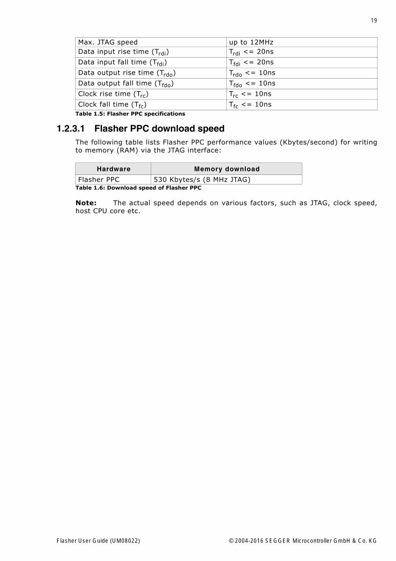
1.2.3.1 Flasher PPC download speedThe following table lists Flasher PPC performance values (Kbytes/second) for writingto memory (RAM) via the JTAG interface:
Note: The actual speed depends on various factors, such as JTAG, clock speed,host CPU core etc.
Max. JTAG speed up to 12MHzData input rise time (Trdi) Trdi <= 20ns
Data input fall time (Tfdi) Tfdi <= 20ns
Data output rise time (Trdo) Trdo <= 10ns
Data output fall time (Tfdo) Tfdo <= 10ns
Clock rise time (Trc) Trc <= 10ns
Clock fall time (Tfc) Tfc <= 10ns
Hardware Memory download
Flasher PPC 530 Kbytes/s (8 MHz JTAG)Table 1.6: Download speed of Flasher PPC
Table 1.5: Flasher PPC specifications
Flasher User Guide (UM08022) © 2004-2016 SEGGER Microcontroller GmbH & Co. KG
20 CHAPTER 1 Introduction
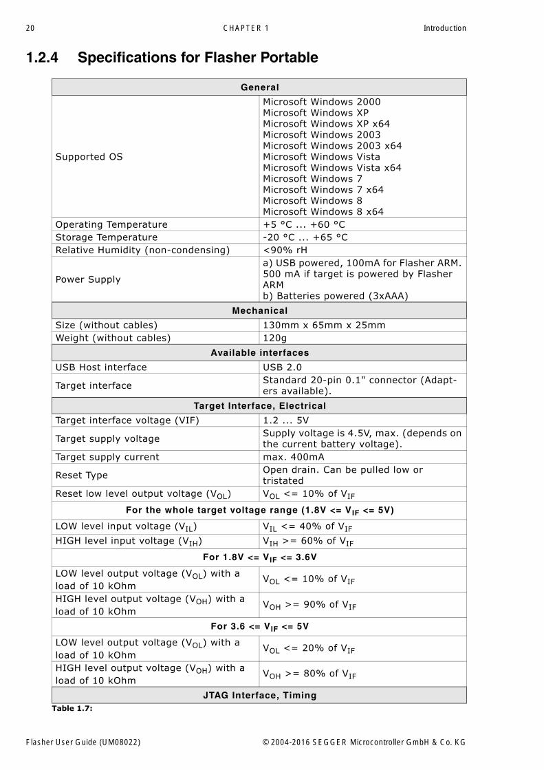
1.2.4 Specifications for Flasher Portable
General
Supported OS
Microsoft Windows 2000Microsoft Windows XPMicrosoft Windows XP x64Microsoft Windows 2003Microsoft Windows 2003 x64Microsoft Windows VistaMicrosoft Windows Vista x64Microsoft Windows 7Microsoft Windows 7 x64Microsoft Windows 8Microsoft Windows 8 x64
Operating Temperature +5 °C ... +60 °CStorage Temperature -20 °C ... +65 °CRelative Humidity (non-condensing) <90% rH
Power Supply
a) USB powered, 100mA for Flasher ARM. 500 mA if target is powered by Flasher ARMb) Batteries powered (3xAAA)
Mechanical
Size (without cables) 130mm x 65mm x 25mmWeight (without cables) 120g
Available interfaces
USB Host interface USB 2.0
Target interface Standard 20-pin 0.1" connector (Adapt-ers available).
Target Interface, Electrical
Target interface voltage (VIF) 1.2 ... 5V
Target supply voltage Supply voltage is 4.5V, max. (depends on the current battery voltage).
Target supply current max. 400mA
Reset Type Open drain. Can be pulled low or tristated
Reset low level output voltage (VOL) VOL <= 10% of VIF
For the whole target voltage range (1.8V <= VIF <= 5V)
LOW level input voltage (VIL) VIL <= 40% of VIF
HIGH level input voltage (VIH) VIH >= 60% of VIF
For 1.8V <= VIF <= 3.6V
LOW level output voltage (VOL) with a load of 10 kOhm
VOL <= 10% of VIF
HIGH level output voltage (VOH) with a load of 10 kOhm
VOH >= 90% of VIF
For 3.6 <= VIF <= 5V
LOW level output voltage (VOL) with a load of 10 kOhm
VOL <= 20% of VIF
HIGH level output voltage (VOH) with a load of 10 kOhm
VOH >= 80% of VIF
JTAG Interface, TimingTable 1.7:
Flasher User Guide (UM08022) © 2004-2016 SEGGER Microcontroller GmbH & Co. KG
21
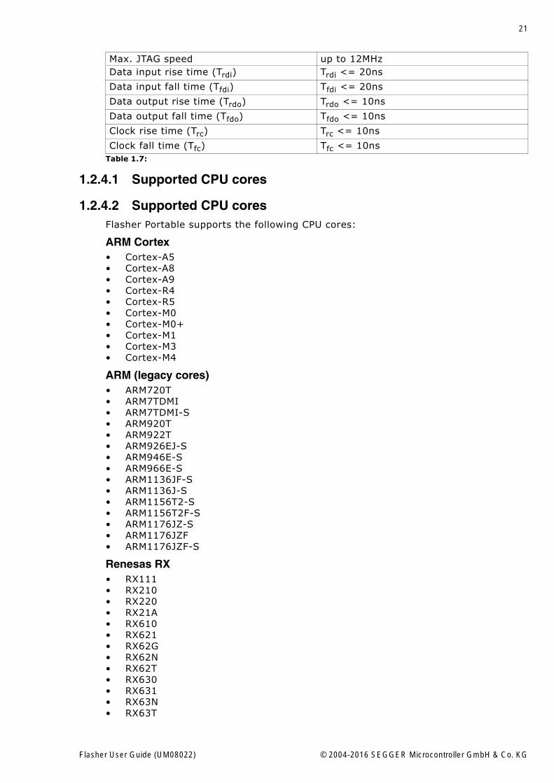
1.2.4.1 Supported CPU cores
1.2.4.2 Supported CPU coresFlasher Portable supports the following CPU cores:
ARM Cortex� Cortex-A5� Cortex-A8� Cortex-A9� Cortex-R4� Cortex-R5� Cortex-M0� Cortex-M0+� Cortex-M1� Cortex-M3� Cortex-M4
ARM (legacy cores)� ARM720T� ARM7TDMI� ARM7TDMI-S� ARM920T� ARM922T� ARM926EJ-S� ARM946E-S� ARM966E-S� ARM1136JF-S� ARM1136J-S� ARM1156T2-S� ARM1156T2F-S� ARM1176JZ-S� ARM1176JZF� ARM1176JZF-S
Renesas RX� RX111� RX210� RX220� RX21A� RX610� RX621� RX62G� RX62N� RX62T� RX630� RX631� RX63N� RX63T
Max. JTAG speed up to 12MHzData input rise time (Trdi) Trdi <= 20ns
Data input fall time (Tfdi) Tfdi <= 20ns
Data output rise time (Trdo) Trdo <= 10ns
Data output fall time (Tfdo) Tfdo <= 10ns
Clock rise time (Trc) Trc <= 10ns
Clock fall time (Tfc) Tfc <= 10nsTable 1.7:
Flasher User Guide (UM08022) © 2004-2016 SEGGER Microcontroller GmbH & Co. KG
22 CHAPTER 1 Introduction
Freescale Power PC� e200z0
1.2.4.3 Supported Target interfacesFlasher Portable supports the following target interfaces:
� JTAG� SWD� FINE� SPD
Flasher User Guide (UM08022) © 2004-2016 SEGGER Microcontroller GmbH & Co. KG
23
Chapter 2
Working with Flasher
This chapter describes functionality and how to use Flasher.
Flasher User Guide (UM08022) © 2004-2016 SEGGER Microcontroller GmbH & Co. KG
24 CHAPTER 2 Working with Flasher
2.1 Flasher PortableFlasher Portable is a portable version of SEGGERs Flasher family, which has beendesigned to fill the need of an extremely portable, production grade, Flash program-mer used for in-field firmware updates. No need to be tethered to an outlet, it ispowered by three standard AAA batteries. Flasher Portable programs flash targets instand-alone mode or via J-Flash PC software.
Furthermore Flasher Portable allows the user to select between four data images tobe programmed. The images can be easily selected by using the arrow buttons on thefront of the housing. For more information about support for multiple images, pleaserefer to Multiple File Support on page 41.
For setup and configuration purposes, the Flasher Portable connects to a PC via USBinterface, running Microsoft Windows 2000, Windows XP, Windows 2003, WindowsVista, Windows 7 or Windows 8 and has a built-in standard 20-pin J-Link target con-nector.
Note: Ethernet and RS232 as host interface are not available for Flasher Porta-ble.
Flasher User Guide (UM08022) © 2004-2016 SEGGER Microcontroller GmbH & Co. KG
25
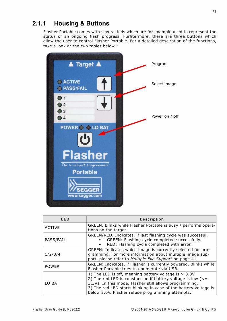
2.1.1 Housing & ButtonsFlasher Portable comes with several leds which are for example used to represent thestatus of an ongoing flash progress. Furhtermore, there are three buttons whichallow the user to control Flasher Portable. For a detailed descirption of the functions,take a look at the two tables below :
LED Description
ACTIVE GREEN. Blinks while Flasher Portable is busy / performs opera-tions on the target.
PASS/FAILGREEN/RED. Indicates, if last flashing cycle was successul.
� GREEN: Flashing cycle completed successfully.� RED: Flashing cycle completed with error.
1/2/3/4GREEN: Indicates which image is currently selected for pro-gramming. For more information about multiple image sup-port, please refer to Multiple File Support on page 41.
POWER GREEN: Indicates, if Flasher is currently powered. Blinks while Flasher Portable tries to enumerate via USB.
LO BAT
1) The LED is off, meaning battery voltage is > 3.3V2) The red LED is constant on if battery voltage is low (<= 3.3V). In this mode, Flasher still allows programming.3) The red LED starts blinking in case of the battery voltage is below 3.0V. Flasher refuse programming attempts.
Program
Select image
Power on / off
Flasher User Guide (UM08022) © 2004-2016 SEGGER Microcontroller GmbH & Co. KG
26 CHAPTER 2 Working with Flasher
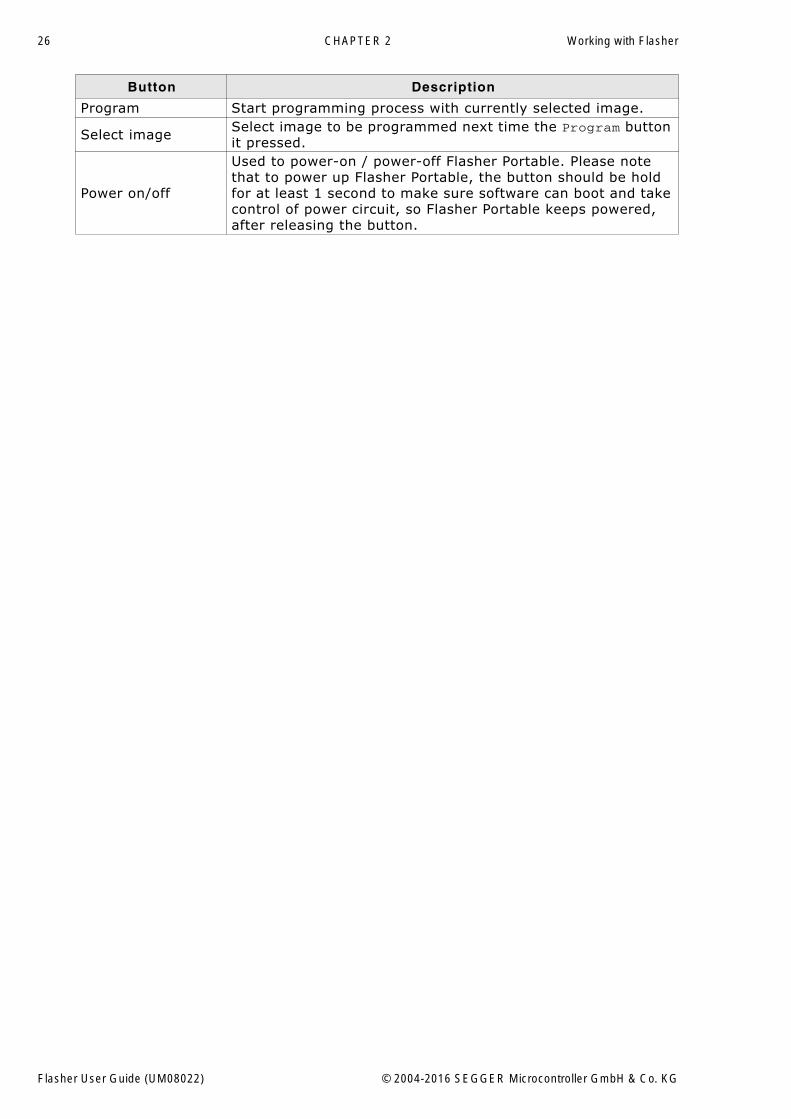
Button Description
Program Start programming process with currently selected image.
Select image Select image to be programmed next time the Program button it pressed.
Power on/off
Used to power-on / power-off Flasher Portable. Please note that to power up Flasher Portable, the button should be hold for at least 1 second to make sure software can boot and take control of power circuit, so Flasher Portable keeps powered, after releasing the button.
Flasher User Guide (UM08022) © 2004-2016 SEGGER Microcontroller GmbH & Co. KG
27
2.2 Setting up the IP interfaceSome of the Flasher models come with an additional Ethernet interface to communi-cate with the host system. These Flashers also come with a built-in webserver whichallows some basic setup of the emulator, e.g. configuring a default gateway whichallows using it even in large intranets.
2.2.1 Connecting the first timeWhen connecting Flasher the first time, it attempts to acquire an IP address viaDHCP. The recommended way for finding out which IP address has been assigned toFlasher is, to use the J-Link Configurator. The J-Link Configurator is a small GUI-based utility which shows a list of all emulator that are connected to the host PC viaUSB and Ethernet. For more information about the J-Link Configurator, please referto UM08001_JLink.pdf (J-Link / J-Trace user guide), chapter Setup, section J-LinkConfigurator. The setup of the IP interface of Flasher is the same as for other emula-tors of the J-Link family. For more information about how to setup the IP interface ofFlasher, please refer to UM08001, J-Link / J-Trace User Guide, chapter Setup, sectionSetting up the IP interface. For more information about how to use Flasher via Ether-net or prepare Flasher via Ethernet for stand-alone mode, please refer to Operatingmodes on page 28.
Flasher User Guide (UM08022) © 2004-2016 SEGGER Microcontroller GmbH & Co. KG
28 CHAPTER 2 Working with Flasher
2.3 Operating modesFlasher is able to boot in 3 different modes:
� J-Link mode� Stand-alone mode� MSD (Mass storage device) mode
Definition J-Link mode
Flasher is connected to a PC via USB/Ethernet and controlled by a PC application (J-Flash). If there is an RS232 connection to a PC, does not have any influence on if J-Link mode is entered or not. In this mode, Flasher can be used as a J-Link and con-trolled by the software in the J-Link software and documentation package (J-LinkCommander, J-Flash, ...)
Definition Stand-alone mode
This mode is entered when there is no active USB/Ethernet connection to a host PC,e.g. if Flasher is only powered via a USB power supply.
Definition MSD mode
Entered only if Flasher Start/Stop button (on Flasher Portable the "PROG" button) iskept pressed for at least 2 seconds while connection Flasher via USB. In this mode,Flasher enumerates as a mass storage device (like an USB Stick) at the host PC. Inthis mode, configuration + data files can be manually placed on the Flasher and theflasher logfile can be read out.
2.3.1 J-Link modeIf you want to use Flasher for the first time you need to install the J-Link softwareand documentation package. After installation, connect Flasher to the host PC viaUSB or Ethernet. For more information about how to install the J-Link software anddocumentation package please refer to the J-Link / J-Trace User Guide, chapterSetup which can be downloaded from http://www.segger.com/download_jlink.html.
2.3.1.1 Connecting the target systemPower-on sequence
In general, Flasher should be powered on before connecting it with the target device.That means you should first connect Flasher with the host system via USB / Ethernetand then connect Flasher with the target device via JTAG or SWD. Power-on thedevice after you connected Flasher to it. Flasher will boot in "J-Link mode".
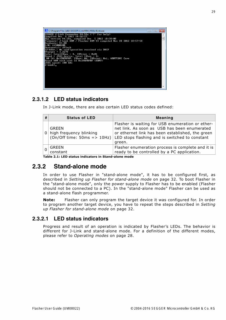
Verifying target device connection with J-Link.exe
If the USB driver is working properly and your Flasher is connected with the host sys-tem, you may connect Flasher to your target hardware. Then start the J-Link com-mand line tool JLink.exe, which should now display the normal Flasher relatedinformation and in addition to that it should report that it found a JTAG target andthe targets core ID. The screenshot below shows the output of JLink.exe.
Flasher User Guide (UM08022) © 2004-2016 SEGGER Microcontroller GmbH & Co. KG
29
2.3.1.2 LED status indicatorsIn J-Link mode, there are also certain LED status codes defined:
2.3.2 Stand-alone modeIn order to use Flasher in "stand-alone mode", it has to be configured first, asdescribed in Setting up Flasher for stand-alone mode on page 32. To boot Flasher inthe "stand-alone mode", only the power supply to Flasher has to be enabled (Flashershould not be connected to a PC). In the "stand-alone mode" Flasher can be used asa stand-alone flash programmer.
Note: Flasher can only program the target device it was configured for. In orderto program another target device, you have to repeat the steps described in Settingup Flasher for stand-alone mode on page 32.
2.3.2.1 LED status indicatorsProgress and result of an operation is indicated by Flasher�s LEDs. The behavior isdifferent for J-Link and stand-alone mode. For a definition of the different modes,please refer to Operating modes on page 28.
# Status of LED Meaning
0GREENhigh frequency blinking(On/Off time: 50ms => 10Hz)
Flasher is waiting for USB enumeration or ether-net link. As soon as USB has been enumerated or ethernet link has been established, the green LED stops flashing and is switched to constant green.
0 GREENconstant
Flasher enumeration process is complete and it is ready to be controlled by a PC application.
Table 2.1: LED status indicators in Stand-alone mode
Flasher User Guide (UM08022) © 2004-2016 SEGGER Microcontroller GmbH & Co. KG
30 CHAPTER 2 Working with Flasher
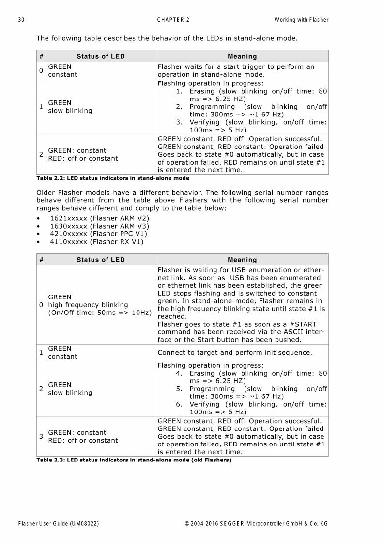
The following table describes the behavior of the LEDs in stand-alone mode.
Older Flasher models have a different behavior. The following serial number rangesbehave different from the table above Flashers with the following serial numberranges behave different and comply to the table below:
� 1621xxxxx (Flasher ARM V2)� 1630xxxxx (Flasher ARM V3)� 4210xxxxx (Flasher PPC V1)� 4110xxxxx (Flasher RX V1)
# Status of LED Meaning
0 GREENconstant
Flasher waits for a start trigger to perform an operation in stand-alone mode.
1 GREENslow blinking
Flashing operation in progress:1. Erasing (slow blinking on/off time: 80
ms => 6.25 HZ)2. Programming (slow blinking on/off
time: 300ms => ~1.67 Hz)3. Verifying (slow blinking, on/off time:
100ms => 5 Hz)
2 GREEN: constantRED: off or constant
GREEN constant, RED off: Operation successful.GREEN constant, RED constant: Operation failedGoes back to state #0 automatically, but in case of operation failed, RED remains on until state #1 is entered the next time.
Table 2.2: LED status indicators in stand-alone mode
# Status of LED Meaning
0GREENhigh frequency blinking(On/Off time: 50ms => 10Hz)
Flasher is waiting for USB enumeration or ether-net link. As soon as USB has been enumerated or ethernet link has been established, the green LED stops flashing and is switched to constant green. In stand-alone-mode, Flasher remains in the high frequency blinking state until state #1 is reached. Flasher goes to state #1 as soon as a #START command has been received via the ASCII inter-face or the Start button has been pushed.
1 GREENconstant Connect to target and perform init sequence.
2 GREENslow blinking
Flashing operation in progress:4. Erasing (slow blinking on/off time: 80
ms => 6.25 HZ)5. Programming (slow blinking on/off
time: 300ms => ~1.67 Hz)6. Verifying (slow blinking, on/off time:
100ms => 5 Hz)
3 GREEN: constantRED: off or constant
GREEN constant, RED off: Operation successful.GREEN constant, RED constant: Operation failedGoes back to state #0 automatically, but in case of operation failed, RED remains on until state #1 is entered the next time.
Table 2.3: LED status indicators in stand-alone mode (old Flashers)
Flasher User Guide (UM08022) © 2004-2016 SEGGER Microcontroller GmbH & Co. KG
31
2.3.3 MSD modeWhen pressing the Start/Stop button of Flasher while connecting it to the PC, Flasherwill boot in the "MSD mode". This mode can be used to downdate a Flasher firmwareversion if a firmware update did not work properly and it can be used to configureFlasher for the "stand-alone mode", without using J-Flash.
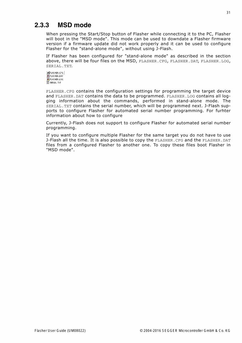
If Flasher has been configured for "stand-alone mode" as described in the sectionabove, there will be four files on the MSD, FLASHER.CFG, FLASHER.DAT, FLASHER.LOG,SERIAL.TXT.
FLASHER.CFG contains the configuration settings for programming the target deviceand FLASHER.DAT contains the data to be programmed. FLASHER.LOG contains all log-ging information about the commands, performed in stand-alone mode. TheSERIAL.TXT contains the serial number, which will be programmed next. J-Flash sup-ports to configure Flasher for automated serial number programming. For furhterinformation about how to configure
Currently, J-Flash does not support to configure Flasher for automated serial numberprogramming.
If you want to configure multiple Flasher for the same target you do not have to useJ-Flash all the time. It is also possible to copy the FLASHER.CFG and the FLASHER.DATfiles from a configured Flasher to another one. To copy these files boot Flasher in"MSD mode".
Flasher User Guide (UM08022) © 2004-2016 SEGGER Microcontroller GmbH & Co. KG
32 CHAPTER 2 Working with Flasher
2.4 Setting up Flasher for stand-alone modeIn order to set up Flasher for the stand-alone mode it needs to be configured onceusing the J-Flash software. For more information about J-Flash, please refer to the J-Flash User Guide.
After starting J-Flash, open the appropriate J-Flash project for the target Flashershall be configured for, by selecting File -> Open Project. If J-Flash does not comewith an appropriate sample project for the desired hardware, a new project needs tobe created by selecting File -> New Project.
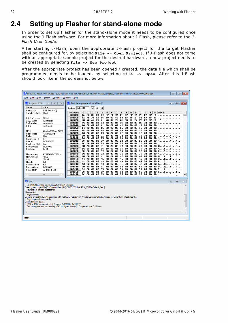
After the appropriate project has been opened / created, the data file which shall beprogrammed needs to be loaded, by selecting File -> Open. After this J-Flashshould look like in the screenshot below.
Flasher User Guide (UM08022) © 2004-2016 SEGGER Microcontroller GmbH & Co. KG
33
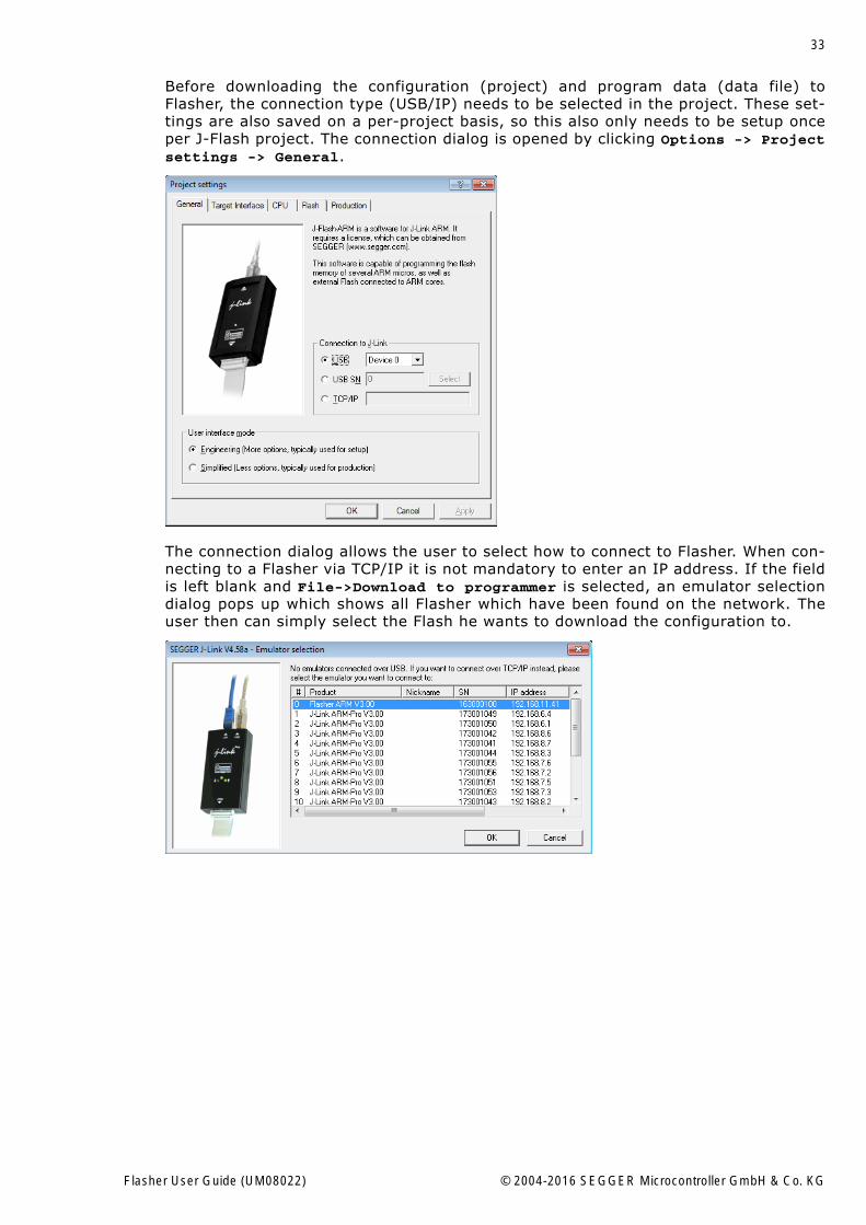
Before downloading the configuration (project) and program data (data file) toFlasher, the connection type (USB/IP) needs to be selected in the project. These set-tings are also saved on a per-project basis, so this also only needs to be setup onceper J-Flash project. The connection dialog is opened by clicking Options -> Projectsettings -> General.
The connection dialog allows the user to select how to connect to Flasher. When con-necting to a Flasher via TCP/IP it is not mandatory to enter an IP address. If the fieldis left blank and File->Download to programmer is selected, an emulator selectiondialog pops up which shows all Flasher which have been found on the network. Theuser then can simply select the Flash he wants to download the configuration to.
Flasher User Guide (UM08022) © 2004-2016 SEGGER Microcontroller GmbH & Co. KG
34 CHAPTER 2 Working with Flasher
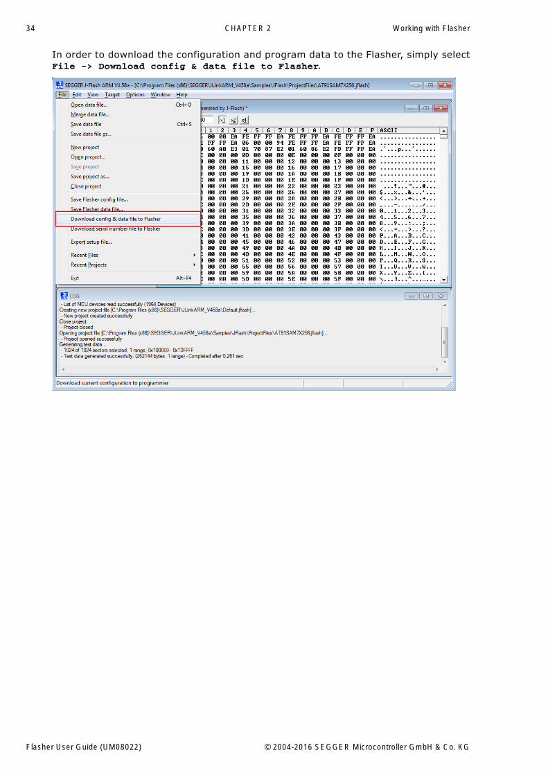
In order to download the configuration and program data to the Flasher, simply selectFile -> Download config & data file to Flasher.
Flasher User Guide (UM08022) © 2004-2016 SEGGER Microcontroller GmbH & Co. KG
35
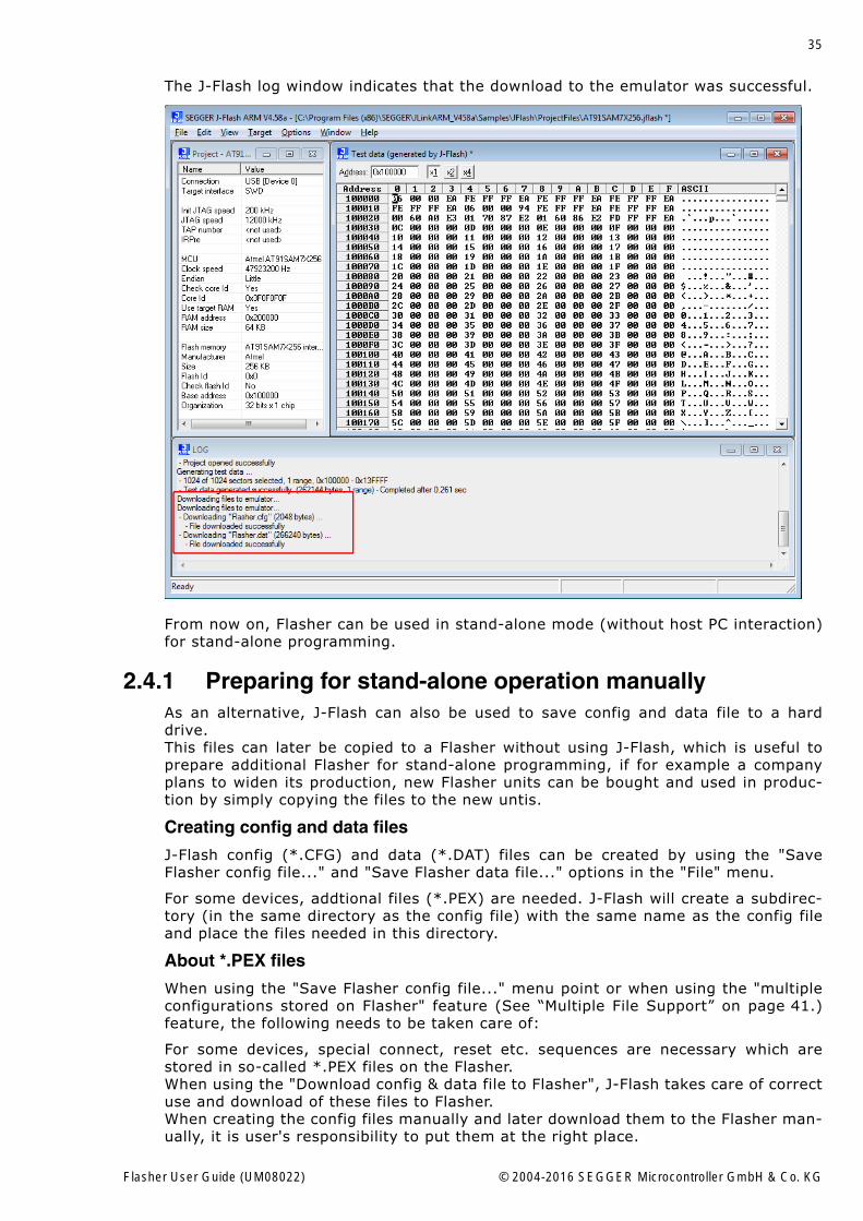
The J-Flash log window indicates that the download to the emulator was successful.
From now on, Flasher can be used in stand-alone mode (without host PC interaction)for stand-alone programming.
2.4.1 Preparing for stand-alone operation manuallyAs an alternative, J-Flash can also be used to save config and data file to a harddrive.This files can later be copied to a Flasher without using J-Flash, which is useful toprepare additional Flasher for stand-alone programming, if for example a companyplans to widen its production, new Flasher units can be bought and used in produc-tion by simply copying the files to the new untis.
Creating config and data files
J-Flash config (*.CFG) and data (*.DAT) files can be created by using the "SaveFlasher config file..." and "Save Flasher data file..." options in the "File" menu.
For some devices, addtional files (*.PEX) are needed. J-Flash will create a subdirec-tory (in the same directory as the config file) with the same name as the config fileand place the files needed in this directory.
About *.PEX files
When using the "Save Flasher config file..." menu point or when using the "multipleconfigurations stored on Flasher" feature (See �Multiple File Support� on page 41.)feature, the following needs to be taken care of:
For some devices, special connect, reset etc. sequences are necessary which arestored in so-called *.PEX files on the Flasher. When using the "Download config & data file to Flasher", J-Flash takes care of correctuse and download of these files to Flasher. When creating the config files manually and later download them to the Flasher man-ually, it is user's responsibility to put them at the right place.
Flasher User Guide (UM08022) © 2004-2016 SEGGER Microcontroller GmbH & Co. KG

36 CHAPTER 2 Working with Flasher
The *.PEX files need to be placed in a subdirectory with the same name as the corre-sponding *.cfg file. J-Flash creates a directory with the correct name automaticallywhen a config file is created.
Example:
MyConf0 is a project for a device that requires a *.PEX file for connect.MyConf1 is a project for a device that requires no *.PEX file at all.
Flasher User Guide (UM08022) © 2004-2016 SEGGER Microcontroller GmbH & Co. KG
37
2.5 Universal Flash Loader modeAs an alternative to the stand-alone mode, configured via J-Flash, there is the Uni-versal Flash Loader mode. While the normal stand-alone mode relies on using thedebug interface of the device, the Universal Flash Loader mode uses device or vendorspecific programming interfaces and protocols and therefore it is independent of theCPU core.
The Universal Flash Loader is available for the Flasher PRO and for the Flasher Porta-ble. For some of the supported devices, SEGGER offers specific adapters.
2.5.1 Preparing manuallyThe Universal Flash Loader uses an initialization file (*.UNI), a device specific flashprogramming algorithm (*.PEX) and a data file (*.HEX, *.MOT, *.BIN or *.DAT).
2.5.1.1 ConfigurationThe initialization file basically is split into three parts. The first part, the section[DEVICE], controls the generic behavior of the Universal Flash Loader. It specifies,which protocol driver and data file to use. It allows to enable and configure targetpowering. And it defines, which actions to perform. The second part consists of oneor more [BANKx] sections, which contain information about the memories. The thirdpart, the section [CONFIG], includes configuration settings for the protocol driver.
An .ini file might be as follows:
[OPTIONS]TargetPower = "0"ChipErase = "0"
[TASKS]CheckBlank = "1"Erase = "1"Program = "1"Verify = "1"
[DEVICE]Algo = "RL78.PEX"Data = "ALL_6k.mot"Offset = "0x00000000"
[BANK0]; Code FlashBase = "0x00000000"Size = "0x00004000"Sect = "0x00000400"
[BANK1]; Data FlashBase = "0x000F1000"Size = "0x00000800"Sect = "0x00000400"
[CONFIG]BaudRate = "1000000"ClearConfigOnConnect = "0x00"Security = "0xFF"ShieldStart = "0x0000"ShieldEnd = "0x000F"
[OPTIONS]
TargetPower
If set to a value >0, power is applied to the target. The value defines the delay (inms) after enabling the target power supply and before starting to communicate withthe target.
ChipErase
If set to 1, the chip erase function is called for erasing the chip.
Flasher User Guide (UM08022) © 2004-2016 SEGGER Microcontroller GmbH & Co. KG
38 CHAPTER 2 Working with Flasher
Note: Do not set enable this setting, if the flash programming algorithm does notsupport chip erase.
[TASKS]
CheckBlank
Defines if a blank check should be performed before erasing a sector.
Erase
Defines if the sector should be erased before programming.
Program
Defines if the sector should be programmed.
Verify
Defines if the sector should be verified after programming.
[DEVICE]
Algo
File name of the flash programming algorithm. This file is provided by SEGGER andwill typically support a series of devices
Data
File name of the data file to program. The flasher supports the Flasher DTA, the IntelHEX, the Motorola S-Record and the binary file format. Flasher DAT files are gener-ated by J-Flash and offer high performance together with high flexibility. The otherfile formats produce a small overhead, because they have to be parsed before thedata can be programmed.
Offset
Offset to apply when programming a binary data file. Unless specified differently,binary files start at offset 0x00000000.
[BANKx]
x blocks with configuration data for the flash banks. All three parameters (Base, Sizeand Sect) are mandatory.
Base
Base address of the flash bank.
Size
Total size of the flash bank.
Sect
Sector size of the flash bank.
[CONFIG]
This section includes specific configuration data for the flash programming algorithm.There are no general parameters.
2.5.1.2 Configuration Data for RL78/G10The RL78/G10 series does not require any configuration data.
Flasher User Guide (UM08022) © 2004-2016 SEGGER Microcontroller GmbH & Co. KG
39
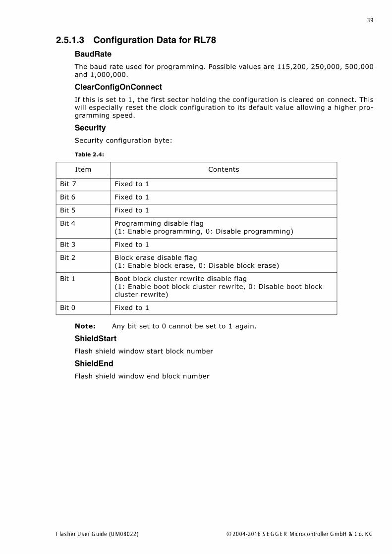
2.5.1.3 Configuration Data for RL78BaudRate
The baud rate used for programming. Possible values are 115,200, 250,000, 500,000and 1,000,000.
ClearConfigOnConnect
If this is set to 1, the first sector holding the configuration is cleared on connect. Thiswill especially reset the clock configuration to its default value allowing a higher pro-gramming speed.
Security
Security configuration byte:
Note: Any bit set to 0 cannot be set to 1 again.
ShieldStart
Flash shield window start block number
ShieldEnd
Flash shield window end block number
Table 2.4:
Item Contents
Bit 7 Fixed to 1
Bit 6 Fixed to 1
Bit 5 Fixed to 1
Bit 4 Programming disable flag(1: Enable programming, 0: Disable programming)
Bit 3 Fixed to 1
Bit 2 Block erase disable flag(1: Enable block erase, 0: Disable block erase)
Bit 1 Boot block cluster rewrite disable flag(1: Enable boot block cluster rewrite, 0: Disable boot block cluster rewrite)
Bit 0 Fixed to 1
Flasher User Guide (UM08022) © 2004-2016 SEGGER Microcontroller GmbH & Co. KG
40 CHAPTER 2 Working with Flasher
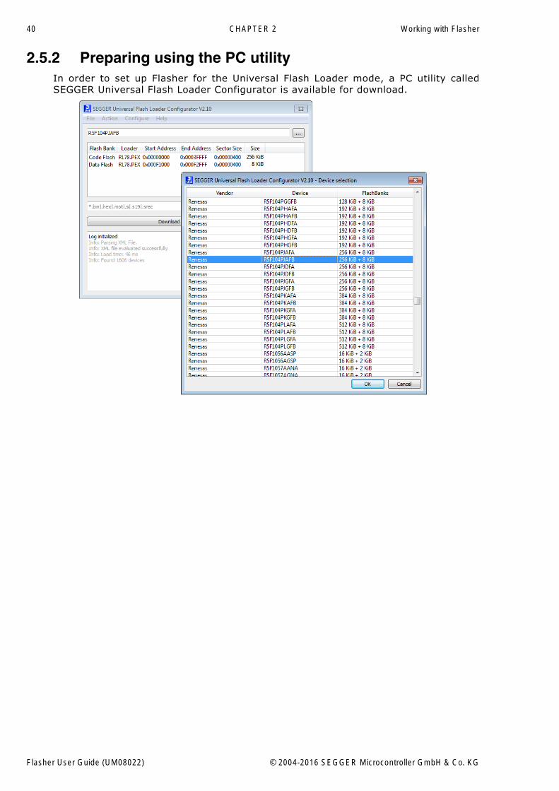
2.5.2 Preparing using the PC utilityIn order to set up Flasher for the Universal Flash Loader mode, a PC utility calledSEGGER Universal Flash Loader Configurator is available for download.
Flasher User Guide (UM08022) © 2004-2016 SEGGER Microcontroller GmbH & Co. KG
41
2.6 Multiple File SupportIt is also possible to have multiple data files and config files on Flasher, to makeFlasher more easy to use in production environment. To choose the correct configura-tion file and data file pair, a FLASHER.INI file is used. This init file contains a [FILES]section which describes which configuration file and which data file should be usedfor programming. A sample content of a FLASHER.INI file is shown below:
[FILES]DataFile = "Flasher1.dat"ConfigFile = "Flasher1.cfg"
Using this method all configuration files and data files which are used in the produc-tion only have to be downloaded once. From there on a configuration file / data filepair can be switched by simply replacing the FLASHER.INI by a new one, which con-tains the new descriptions for the configuration file and data file. The FLASHER.INIcan be replaced in two ways:
1. Boot Flasher in MSD mode in order to replace the FLASHER.INI2. If Flasher is already integrated into the production line, runs in stand-alone mode
and can not be booted in other mode: Use the file I/O commands provided by theASCII interface of Flasher, to replace the FLASHER.INI. For more informationabout the file I/O commands, please refer to File I/O commands on page 70.
Note: Flasher supports 8.3 filenames only (8 characters filename, 3 charactersfile extension). Using longer filenames may result in incorrect operation.
2.6.1 Flasher Portable specificsFlasher Portable allows to choose between four configuration and data file pairs dur-ing runtime by using the select/arrow button on the front of Flasher Portable.
Which config / data file pair is used for which image selection position is determinedby the contents of the FLASHER.INI. For this, the FLASHER.INI contents in the[FILES] section have been extended. The sample below shows how to enable theuser to select between four different images on the Flasher portable via the select /arrow button:
[FILES]DataFile = "First.dat"ConfigFile = "First.cfg"DataFile1 = "Second.dat"ConfigFile1 = "Second.cfg"DataFile2 = "Third.dat"ConfigFile2 = "Third.cfg"DataFile3 = "Fourth.dat"ConfigFile3 = "Fourth.cfg"
Using this method, all configuration files and data files which are used in the produc-tion only have to be stored on Flasher Portable via MSD mode. From there on, switch-ing between the files can be done by simply using the selection button of FlasherPortable.
Flasher User Guide (UM08022) © 2004-2016 SEGGER Microcontroller GmbH & Co. KG
42 CHAPTER 2 Working with Flasher
2.6.2 Example1 Target, 2 Datenfiles (e.g. boot loader und application) --> same configuration file(*.CFG) but different data files (*.DAT) should be used.
� Open pre-configured J-Flash project� File -> Save Flasher config file ... (DEFAULT.CFG)� Open data file 1 (boot loader)� File -> Save Flasher data file ... (BOOT.DAT)� Open data file 2 (application)� File -> Save Flasher data file ... (APP.DAT)� Create the a FLASHER.INI file (content see below)� Connect the Flasher in MSD mode to the PC� Copy DEFAULT.CFG, BOOT.DAT, APP.DAT and FLASHER.INI on the Flasher
FLASHER.INI content:
[FILES]DataFile = "BOOT.DAT"ConfigFile = "DEFAULT.CFG"DataFile1 = "APP.DAT"ConfigFile1 = "DEFAULT.CFG"
Flasher User Guide (UM08022) © 2004-2016 SEGGER Microcontroller GmbH & Co. KG
43
2.7 Programming multiple targetsIt is possible to program multiple targets which are located in a JTAG chain. The tar-gets will be programmed each with a configuration and a data file. The configurationfor the desired target must be selected before it can be programmed, this can bedone with the #SELECT command. For more information how to use the #SELECT com-mand please refer to Chapter "3.3.5 Commands to Flasher".
Example
Three devices should be programmed.
JTAG Chain: TDI --> Device2 --> Device1 --> Device0 --> TDO
Three configurations would be stored on the flasher:
Config 0: Configured to program Device0 (DEVICE0.CFG, DEVICE0.DAT)Config 1: Configured to program Device1 (DEVICE1.CFG, DEVICE1.DAT)Config 2: Configured to program Device2 (DEVICE2.CFG, DEVICE2.DAT)
Selection and programming of the target will be done via the ASCII interface:
#SELECT DEVICE0#AUTO#SELECT DEVICE1#AUTO#SELECT DEVICE2#AUTO
2.7.1 Programming multiple targets with J-FlashProgramming multiple targets can also be done via J-Flash using the command lineinterface. For this each target must be handled with its own project file.
Example
JFlash.exe -openproj"Device0.jflash" -open"Device0.hex" -auto -exitJFlash.exe -openproj"Device1.jflash" -open"Device1.hex" -auto -exitJFlash.exe -openproj"Device2.jflash" -open"Device2.hex" -auto -exit
Flasher User Guide (UM08022) © 2004-2016 SEGGER Microcontroller GmbH & Co. KG
44 CHAPTER 2 Working with Flasher
2.8 Batch Programming in stand-alone modeBatch programming allows to execute different stand-alone mode jobs in batch to beexecuted in immediate succession, without any user interaction in between. This canbe used for example to program multiple targets in a JTAG-Chain or multiple datafiles to a target. A batch may contains an unlimited number of configurations which consist of a datafile (*.DAT) and config file (*.CFG). For further information regarding config and datafiles, please refer to Preparing for stand-alone operation manually on page 35).
In order to specifiy the batch jobs, a FLASHER.INI file is used. This init file contains a[BATCH] section which describes which configuration pairs (*.DAT and *.CFG file)should be used for each batch job.A sample content of a FLASHER.INI file is shown below:
[BATCH]DataFile = "Flasher0.dat"ConfigFile = "Flasher0.cfg"DataFile1 = "Flasher1.dat"ConfigFile1 = "Flasher1.cfg"
Creating / Replacing of the FLASHER.INI file can done in two ways:
1. Boot Flasher in MSD mode in order to replace the FLASHER.INI2. If Flasher is already integrated into the production line, runs in stand-alone
modeand can not be booted in other mode: Use the file I/O commands providedby the ASCII interface of Flasher, to replace the FLASHER.INI . For more informa-tion about the file I/O commands, please refer to File I/O commands on page 70.
In case of an error occured during execution, the Flasher terminates the entire batchprocessing.
Note: Please note that the batch programming feature can not be used with themultiple file support feature. Therefore, neither the #SELECT ASCII command norethe [FILES] tag in the FLASHER.INI file can be used.
Note: Flasher supports 8.3 filenames only (8 characters filename, 3 charactersfile extension). Using longer filenames may result in incorrect operation.
2.8.1 Flasher Portable specificsFlasher Portable allows to choose between four different batches during runtime byusing the select/arrow button on the front of Flasher Portable. Which batch configu-ration is used for which image selection position is specified in the FLASHER.INI. Forthis, the FLASHER.INI contents in the [BATCH] section have been extended. Thesample below shows how to enable the user to select between four different batcheson the Flasher Portable via the select / arrow button:
[BATCH]DataFile = "Flasher0.dat"ConfigFile = "Flasher0.cfg"DataFile1 = "Flasher1.dat"ConfigFile1 = "Flasher1.cfg"DataFile2 = "Flasher2.dat"ConfigFile2 = "Flasher2.cfg"[BATCH1]DataFile = "TEST.dat"ConfigFile = "Test.cfg"[BATCH2]DataFile = "VALIDATE.dat"ConfigFile = "Flasher0.cfg"
Using this method allows to have different batches for different setups used in theproduction to be stored once on the Flasher Portable via MSD mode. From there on,switching between the batches can be done by simply using the selection button ofFlasher Portable.
Flasher User Guide (UM08022) © 2004-2016 SEGGER Microcontroller GmbH & Co. KG
45
2.8.2 ExamplesExample 1: Programming two Data files to the same target
� Open your J-Flash project.� Use File -> Save Flasher config file... to save the .CFG file (in this example:
STM32F4.CFG).� Select the first binary and use File -> Save Flasher Data file... to save the first
.DAT file (in this example: DATA0.DAT).� Select the second binary and use File -> Save Flasher Data file... to save the sec-
ond data file .DAT file (in this example: DATA1.DAT).� Copy the Files to the Flasher e.g. by using MSD mode. � Create a FLASHER.INI file in the root directory of the Flasher. � Exemplary content of FLASHER.INI:
[BATCH]DataFile = "DATA0.dat"ConfigFile = "STM32F4.cfg"DataFile1 = "DATA1.dat"ConfigFile1 = "STM32F4.cfg"
Example 2: Programming one Data file to the first target in a JTAG-Chain and thenprogramming two data files to another device in the JTAG chain.Example scenario: 2 Devices in a JTAG chain, a STM32F1 and a STM32F4.
� Follow the same as described before and additionally:� Create one project file per target (and create a .CFG file of each one).� Make sure each project file is configured correctly, especially the JTAG-Chain
position (See UM8003 "J-Flash" for more detailed info).� Exemplary content of FLASHER.INI:
[BATCH]DataFile = "F1DATA.dat"ConfigFile = "STM32F1.cfg"DataFile1 = "F4DATA0.dat"ConfigFile1 = "STM32F4.cfg"DataFile2 = "F4DATA1.dat"ConfigFile2 = "STM32F4.cfg"
Example 3: Using multiple Batch sections with Flasher Portable.Example scenario: 2 Devices in a JTAG chain, a STM32F1 and a STM32F4. Selection 1 will program the STM32F1 target.Selection 2 will program the STM32F4 target using "F4DATA0.dat".Selection 3 will program the STM32F4 target using "F4DATA1.dat".Selection 4 will execute 1, 2 and 3 in sequence.
� Exemplary content of FLASHER.INI:[BATCH]DataFile = "F1DATA.dat"ConfigFile = "STM32F1.cfg"[BATCH1]DataFile = "F4DATA0.dat"ConfigFile = "STM32F4.cfg"[BATCH2]DataFile = "F4DATA1.dat"ConfigFile = "STM32F4.cfg"[BATCH3]DataFile = "F1DATA.dat"ConfigFile = "STM32F1.cfg"DataFile1 = "F4DATA0.dat"ConfigFile1 = "STM32F4.cfg"DataFile2 = "F4DATA1.dat"ConfigFile2 = "STM32F4.cfg"
Flasher User Guide (UM08022) © 2004-2016 SEGGER Microcontroller GmbH & Co. KG
46 CHAPTER 2 Working with Flasher
2.9 Serial number programmingFlasher supports programming of serial numbers. In order to use the serial numberprogramming feature, the J-Flash project to be used as well as some files on theFlasher (depending on the configuration) need to be configured first.
In general, Flasher supports two ways of programming a serial number into the tar-get:
1. Programming continuous serial numbers. Serial number is 1-4 bytes in size. Startserial number, increment, serial number size and address is configured in the J-Flashproject.
2. Programming custom serial numbers from a serial number list file. Start line intoserial number list file to get next serial number bytes, line increment, serial num-ber size and address is configured in J-Flash project. Serial number list file needsto be specified and created by user.
In the following some generic information how to setup Flasher & the J-Flash projectfor serial number programming are given.
Note: Full serial number programming support has been introduced with V4.51dof the J-Flash software and the Flasher firmware that comes with it.
Note: Currently, programming of serial numbers is only supported for stand-alone mode. Future versions of J-Flash may also support serial number programmingin J-Link mode.
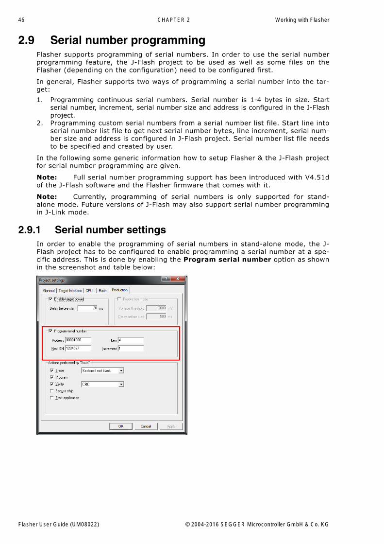
2.9.1 Serial number settingsIn order to enable the programming of serial numbers in stand-alone mode, the J-Flash project has to be configured to enable programming a serial number at a spe-cific address. This is done by enabling the Program serial number option as shownin the screenshot and table below:
Flasher User Guide (UM08022) © 2004-2016 SEGGER Microcontroller GmbH & Co. KG
47
2.9.2 Serial number fileWhen selecting File -> Download serial number file to Flasher, J-Flash will cre-ate a Serial number file named as <JFlashProjectName>_Serial.txt. This file isdownloaded as SERIAL.TXT on Flasher. The file is generated based on the serial num-ber settings in the J-Flash project and will contain the value defined by the Next SNoption. The serial number file can also be manually edited by the user, since theserial number is written ASCII encoded in the SERIAL.TXT file.
2.9.3 Serial number list fileIn order to program custom serial numbers which can not be covered by the standardserial number scheme provided by J-Flash (e.g. when programming non-continuousserial numbers or having gaps between the serial numbers), a so called serial num-ber list file needs to be created by the user.
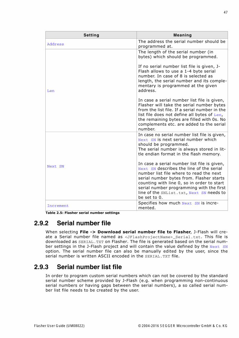
Setting Meaning
AddressThe address the serial number should be programmed at.
Len
The length of the serial number (in bytes) which should be programmed.
If no serial number list file is given, J-Flash allows to use a 1-4 byte serial number. In case of 8 is selected as length, the serial number and its comple-mentary is programmed at the given address.
In case a serial number list file is given, Flasher will take the serial number bytes from the list file. If a serial number in the list file does not define all bytes of Len, the remaining bytes are filled with 0s. No complements etc. are added to the serial number.
Next SN
In case no serial number list file is given, Next SN is next serial number which should be programmed.The serial number is always stored in lit-tle endian format in the flash memory.
In case a serial number list file is given, Next SN describes the line of the serial number list file where to read the next serial number bytes from. Flasher starts counting with line 0, so in order to start serial number programming with the first line of the SNList.txt, Next SN needs to be set to 0.
IncrementSpecifies how much Next SN is incre-mented.
Table 2.5: Flasher serial number settings
Flasher User Guide (UM08022) © 2004-2016 SEGGER Microcontroller GmbH & Co. KG
48 CHAPTER 2 Working with Flasher
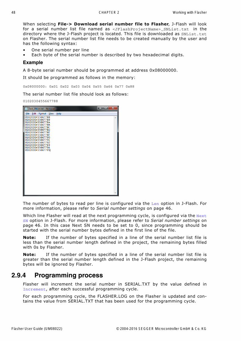
When selecting File-> Download serial number file to Flasher, J-Flash will lookfor a serial number list file named as <JFlashProjectName>_SNList.txt in thedirectory where the J-Flash project is located. This file is downloaded as SNList.txton Flasher. The serial number list file needs to be created manually by the user andhas the following syntax:
� One serial number per line� Each byte of the serial number is described by two hexadecimal digits.
Example
A 8-byte serial number should be programmed at address 0x08000000.
It should be programmed as follows in the memory:
0x08000000: 0x01 0x02 0x03 0x04 0x55 0x66 0x77 0x88
The serial number list file should look as follows:
0102030455667788
The number of bytes to read per line is configured via the Len option in J-Flash. Formore information, please refer to Serial number settings on page 46.
Which line Flasher will read at the next programming cycle, is configured via the NextSN option in J-Flash. For more information, please refer to Serial number settings onpage 46. In this case Next SN needs to be set to 0, since programming should bestarted with the serial number bytes defined in the first line of the file.
Note: If the number of bytes specified in a line of the serial number list file isless than the serial number length defined in the project, the remaining bytes filledwith 0s by Flasher.
Note: If the number of bytes specified in a line of the serial number list file isgreater than the serial number length defined in the J-Flash project, the remainingbytes will be ignored by Flasher.
2.9.4 Programming processFlasher will increment the serial number in SERIAL.TXT by the value defined inIncrement, after each successful programming cycle.
For each programming cycle, the FLASHER.LOG on the Flasher is updated and con-tains the value from SERIAL.TXT that has been used for the programming cycle.
Flasher User Guide (UM08022) © 2004-2016 SEGGER Microcontroller GmbH & Co. KG
49
Note: The serial number in SERIAL.TXT will also be incremented in case if serialnumber programming is disabled, to make sure that for the Flasher logfile there is areference which programming cycle passed and which not. As long as serial numberprogramming has not been enabled in the J-Flash project, Flasher does not mergeany serial number data into the image data to be programmed.
2.9.5 Downloading serial number files to FlasherDownloading the serial number files needs to be done explicitly by selecting File->Download serial number file to Flasher. Please note that the File -> Downloadconfig & data file to Flasher option does only download the configuration and datafile to Flasher since usually the current serial number used for programming shall notbe reset/overwritten when just updating the image Flasher shall program.
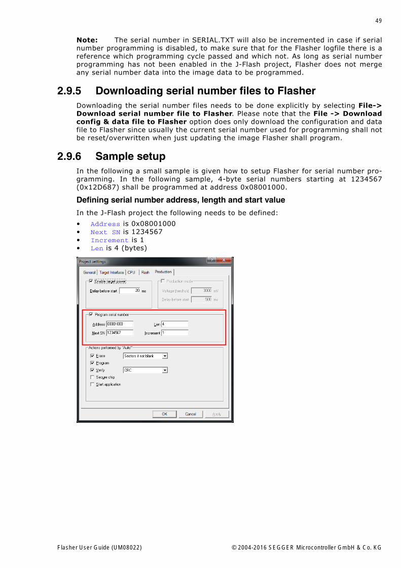
2.9.6 Sample setupIn the following a small sample is given how to setup Flasher for serial number pro-gramming. In the following sample, 4-byte serial numbers starting at 1234567(0x12D687) shall be programmed at address 0x08001000.
Defining serial number address, length and start value
In the J-Flash project the following needs to be defined:
� Address is 0x08001000� Next SN is 1234567� Increment is 1� Len is 4 (bytes)
Flasher User Guide (UM08022) © 2004-2016 SEGGER Microcontroller GmbH & Co. KG
50 CHAPTER 2 Working with Flasher
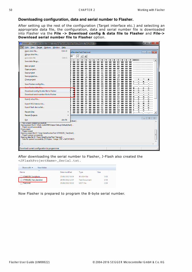
Downloading configuration, data and serial number to Flasher.
After setting up the rest of the configuration (Target interface etc.) and selecting anappropriate data file, the configuration, data and serial number file is downloadedinto Flasher via the File -> Download config & data file to Flasher and File->Download serial number file to Flasher option.
After downloading the serial number to Flasher, J-Flash also created the<JFlashProjectName>_Serial.txt.
Now Flasher is prepared to program the 8-byte serial number.
Flasher User Guide (UM08022) © 2004-2016 SEGGER Microcontroller GmbH & Co. KG
51
2.10 Patch file supportIn stand-alone mode Flasher supports patch files which allows to patch the content ofthe data to be programmed. Before starting programming process in stand-alonemode, Flasher will look for a file named Patches.txt being present on the Flasher.This file includes the patches. If this file is present, the number in Serial.txtdescribes the line number of the Patches.txt that will be used for the current cycle(line counting starts at 0).
Each line in the Patches.txt can hold up to 4 patches, where each patch can be upto 32 bytes in length.
Syntax
Each line begins with <NumPatches> followed by each patch <Addr>,<NumBytes>:<Data>in sequence and separated by commas. So the syntax for <NumPatches>==4 would beas follows:
<NumPatches>,<Addr>,<NumBytes>:<Data>,<Addr>,<NumBytes>:<Data>,<Addr>,<NumBytes>:<Data>,<Addr>,<NumBytes>:<Data>\r\n
Find below a table which describes each parameter.
Note: All values are expected in hexadecimal format (hex). <Data> section is always preceeded by ":", not ",".
Example
Please find below a sample sequence which clarifies the usage of patch files.
Patches.txt, which is located on the Flasher, contains the following line:
3,100025,3:AABBCC,100063,2:DDEE,100078,1:FF
Serial.txt contains a "0" which force the Flasher to use line 0 from Patches.txt.
After starting the programming cycle, the following data will be patched:
Addr 0x100025: 3 byte 0xAA 0xBB 0xCCAddr 0x100063: 2 byte 0xDD 0xEEAddr 0x100078: 1 byte 0xFF
Single patch via RS232
Alternatively, you can start a programming cycle with patch data that is only valid forthis one cycle (no need for a Patches.txt file):
Send the #AUTO PATCH <NumPatches>,<Addr>,<NumBytes>:<Data>
command via Flasher ASCII interface. The parameters have the same function asdescribed in the table above.
Parameter Description
<NumPatches>Describes the number of patches in this patch line. Max. value is 4.
<Addr>Describes the address to be patched. Value is expected in hex.
<NumBytes>Number of bytes for the current patch. Max. value is 20h (32 in decimal).Value is expected in hex.
<Data>Describes the data to be patched. <Data> is always expected as 2 hexa-decimal characters per byte.
Flasher User Guide (UM08022) © 2004-2016 SEGGER Microcontroller GmbH & Co. KG
52 CHAPTER 2 Working with Flasher
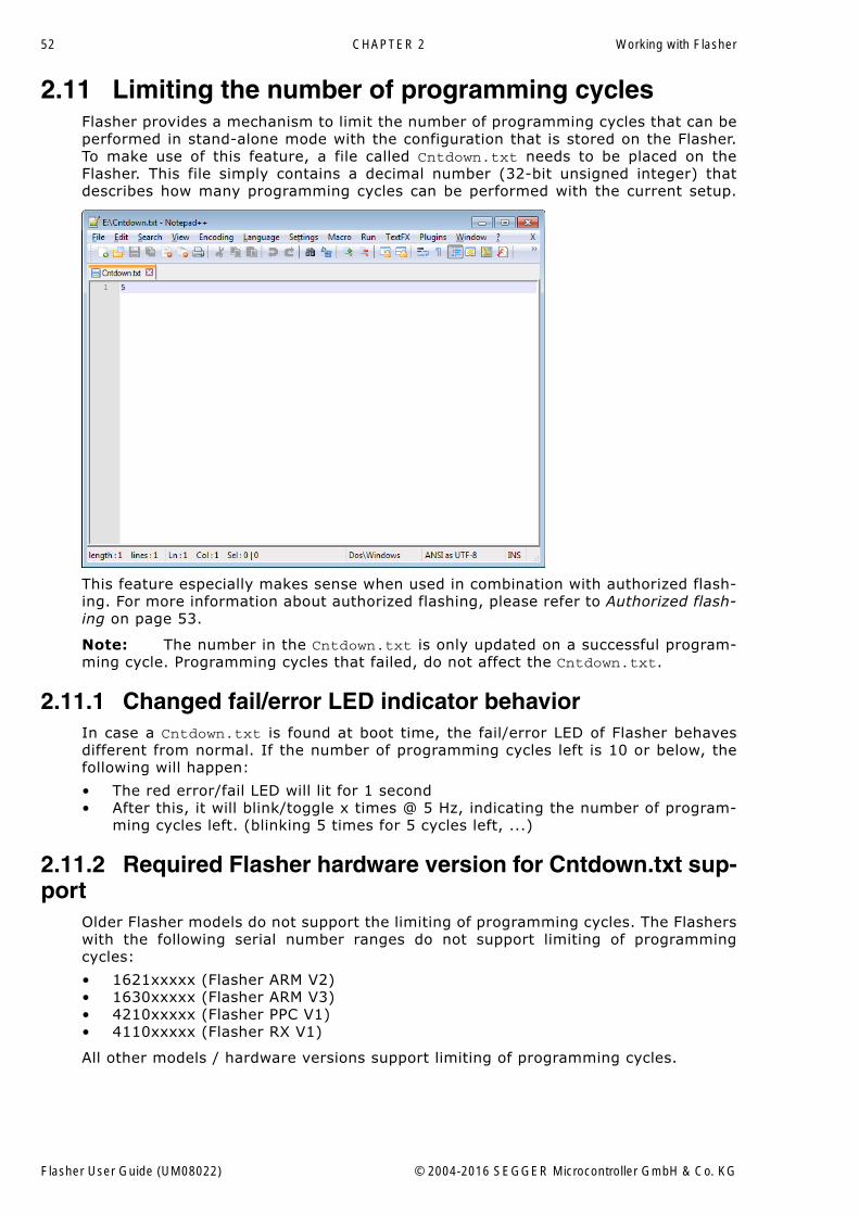
2.11 Limiting the number of programming cyclesFlasher provides a mechanism to limit the number of programming cycles that can beperformed in stand-alone mode with the configuration that is stored on the Flasher.To make use of this feature, a file called Cntdown.txt needs to be placed on theFlasher. This file simply contains a decimal number (32-bit unsigned integer) thatdescribes how many programming cycles can be performed with the current setup.
This feature especially makes sense when used in combination with authorized flash-ing. For more information about authorized flashing, please refer to Authorized flash-ing on page 53.
Note: The number in the Cntdown.txt is only updated on a successful program-ming cycle. Programming cycles that failed, do not affect the Cntdown.txt.
2.11.1 Changed fail/error LED indicator behaviorIn case a Cntdown.txt is found at boot time, the fail/error LED of Flasher behavesdifferent from normal. If the number of programming cycles left is 10 or below, thefollowing will happen:
� The red error/fail LED will lit for 1 second� After this, it will blink/toggle x times @ 5 Hz, indicating the number of program-
ming cycles left. (blinking 5 times for 5 cycles left, ...)
2.11.2 Required Flasher hardware version for Cntdown.txt sup-port
Older Flasher models do not support the limiting of programming cycles. The Flasherswith the following serial number ranges do not support limiting of programmingcycles:
� 1621xxxxx (Flasher ARM V2)� 1630xxxxx (Flasher ARM V3)� 4210xxxxx (Flasher PPC V1)� 4110xxxxx (Flasher RX V1)
All other models / hardware versions support limiting of programming cycles.
Flasher User Guide (UM08022) © 2004-2016 SEGGER Microcontroller GmbH & Co. KG
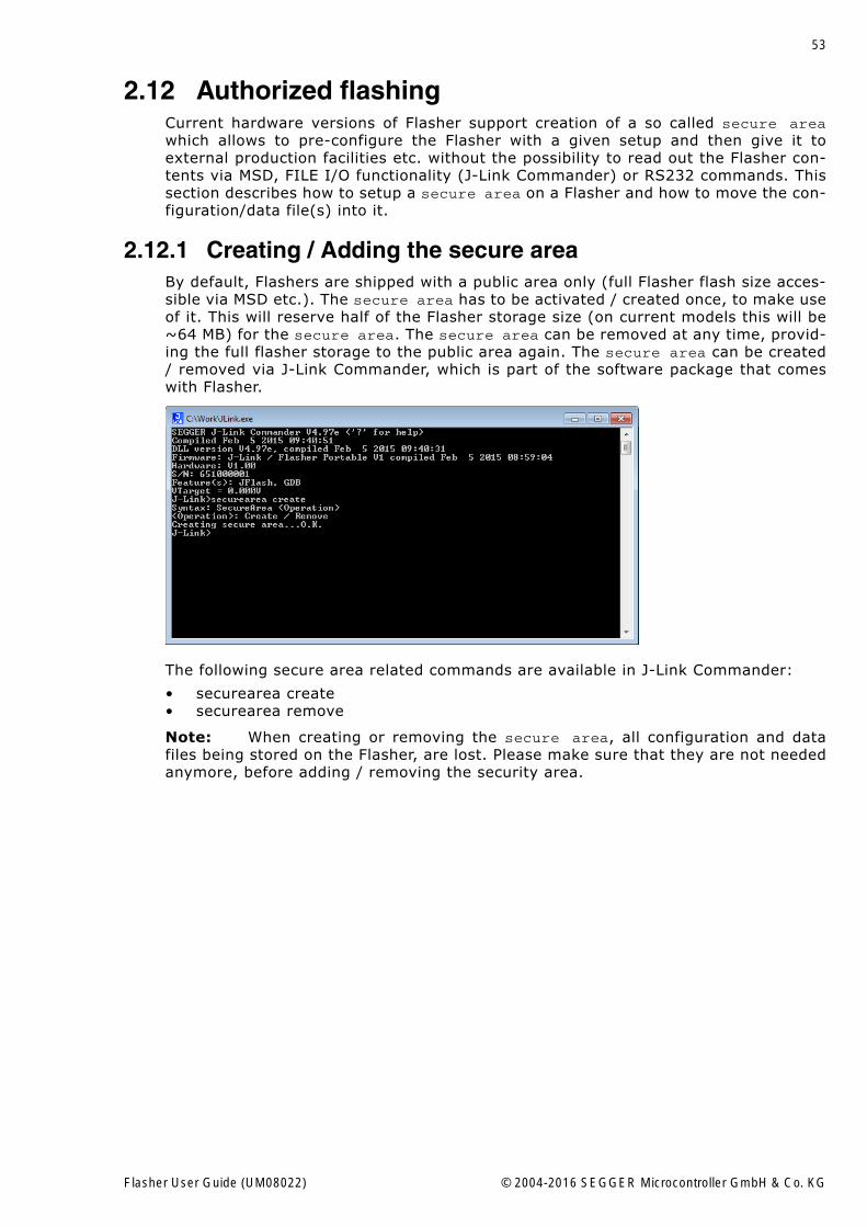
53
2.12 Authorized flashingCurrent hardware versions of Flasher support creation of a so called secure areawhich allows to pre-configure the Flasher with a given setup and then give it toexternal production facilities etc. without the possibility to read out the Flasher con-tents via MSD, FILE I/O functionality (J-Link Commander) or RS232 commands. Thissection describes how to setup a secure area on a Flasher and how to move the con-figuration/data file(s) into it.
2.12.1 Creating / Adding the secure areaBy default, Flashers are shipped with a public area only (full Flasher flash size acces-sible via MSD etc.). The secure area has to be activated / created once, to make useof it. This will reserve half of the Flasher storage size (on current models this will be~64 MB) for the secure area. The secure area can be removed at any time, provid-ing the full flasher storage to the public area again. The secure area can be created/ removed via J-Link Commander, which is part of the software package that comeswith Flasher.
The following secure area related commands are available in J-Link Commander:
� securearea create� securearea remove
Note: When creating or removing the secure area, all configuration and datafiles being stored on the Flasher, are lost. Please make sure that they are not neededanymore, before adding / removing the security area.
Flasher User Guide (UM08022) © 2004-2016 SEGGER Microcontroller GmbH & Co. KG
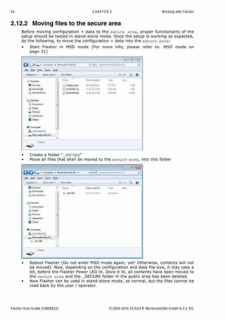
54 CHAPTER 2 Working with Flasher
2.12.2 Moving files to the secure areaBefore moving configuration + data to the secure area, proper functionality of thesetup should be tested in stand-alone mode. Once the setup is working as expected,do the following, to move the configuration + data into the secure area:
� Start Flasher in MSD mode (For more info, please refer to: MSD mode onpage 31)
� Create a folder "_SECURE"� Move all files that shall be moved to the secure area, into this folder
� Reboot Flasher (Do not enter MSD mode again, yet! Otherwise, contents will notbe moved). Now, depending on the configuration and data file size, it may take abit, before the Flasher Power LED lit. Once it lit, all contents have been moved tothe secure area and the _SECURE folder in the public area has been deleted.
� Now Flasher can be used in stand-alone mode, as normal, but the files cannot beread back by the user / operator.
Flasher User Guide (UM08022) © 2004-2016 SEGGER Microcontroller GmbH & Co. KG
55
2.12.3 Considerations to be taken when using the secure areaWhen using the secure area, some things need to be considered:
� All features like multiple file support, patch file support etc. can also be usedwhen operating from the secure area.
� The secure area cannot be read back by any utility. Solely the FLASHER.LOG isalways placed and updated in the public area, even when Flasher operates fromthe secure area.
� If there is any file/folder in the public area, except the FLASHER.LOG and there isalso any configuration / data present in the secure area, stand-alone flashingwill fail because it is not unambiguous which configuration / data shall be used.In such cases, Flashers with Ethernet / RS232 interface will output an appropri-ate error message on programming. All Flasher models will output an appropriateerror message in the FLASHER.LOG.
� Moving files from the public into the secure area can be done multiple times, asexplained in Moving files to the secure area on page 54. Each time files aremoved from the public area to the secure area, all contents of the secure areaare erased first, to make sure that no previous configuration is present there.
2.12.4 Required Flasher hardware versionOlder Flasher models do not support authorized flashing. The Flashers with the fol-lowing serial number ranges do not support authorized flashing:
� 1621xxxxx (Flasher ARM V2)� 1630xxxxx (Flasher ARM V3)� 4210xxxxx (Flasher PPC V1)� 4110xxxxx (Flasher RX V1)
All other models / hardware versions support authorized flashing.
Flasher User Guide (UM08022) © 2004-2016 SEGGER Microcontroller GmbH & Co. KG
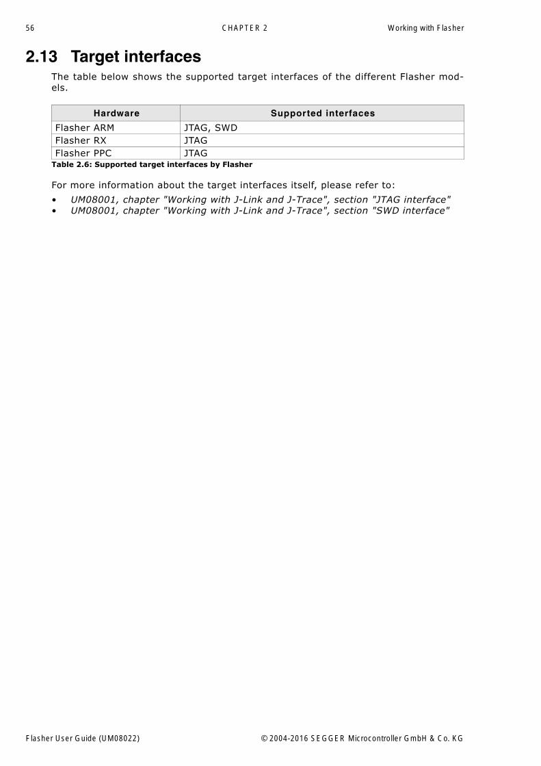
56 CHAPTER 2 Working with Flasher
2.13 Target interfacesThe table below shows the supported target interfaces of the different Flasher mod-els.
For more information about the target interfaces itself, please refer to:
� UM08001, chapter "Working with J-Link and J-Trace", section "JTAG interface"� UM08001, chapter "Working with J-Link and J-Trace", section "SWD interface"
Hardware Supported interfaces
Flasher ARM JTAG, SWDFlasher RX JTAGFlasher PPC JTAG
Table 2.6: Supported target interfaces by Flasher
Flasher User Guide (UM08022) © 2004-2016 SEGGER Microcontroller GmbH & Co. KG
57
2.14 Supported microcontrollers
2.14.1 FlasherFlasher supports download into the internal flash of a large number of microcontrol-lers. The number of supported devices is steadily growing, so you can always find thelatest list of supported devices on our website:
http://www.segger.com/supported-devices.html
Flasher User Guide (UM08022) © 2004-2016 SEGGER Microcontroller GmbH & Co. KG
58 CHAPTER 2 Working with Flasher
2.15 Support of external flashes
2.15.1 Flasher ARMIn general Flasher ARM supports programming of external flashes listed below:
� parallel NOR flash� serial NOR flash� NAND flash� DataFlash
If the parallel NOR flash device which is used is not CFI-compliant you have to selectthe flash device in J-Flash explicitly, for a list of all parallel NOR flash devices whichcan be explicitly selected in J-Flash, please refer to UM08003, J-Flash User Guide,chapter Supported Flash Devices. For serial NOR flash, NAND flash and DataFlashdevices a custom RAMCode is needed since the connection of the flash to the CPU dif-fers from device to device. The J-Flash software comes with sample projects for cus-tom RAMCodes. For a complete list of all custom RAMCode projects which come withthe J-Flash software, please refer to: http://www.segger.com/supported-devices.html
2.15.2 Flasher RXProgramming of external parallel NOR flash is currently not supported by Flasher RX.This limitation will be lifted in the near future.
2.15.3 Flasher PPCProgramming of external parallel NOR flash is currently not supported by FlasherPPC. This limitation will be lifted in the near future.
Flasher User Guide (UM08022) © 2004-2016 SEGGER Microcontroller GmbH & Co. KG
59
2.16 Supported cores
2.16.1 Flasher ARMFlasher ARM supports and has been tested with the following cores, but should workwith any ARM7/9, Cortex-M0/M1/M3/M4 core. If you experience problems with a par-ticular core, do not hesitate to contact Segger.
� ARM7TDMI (Rev 1)� ARM7TDMI (Rev 3)� ARM7TDMI-S (Rev 4)� ARM920T� ARM922T� ARM926EJ-S� ARM946E-S� ARM966E-S� Cortex-M0� Cortex-M1� Cortex-M3� Cortex-M4
2.16.2 Flasher RXFlasher RX supports and has been tested with the following cores. If you experienceproblems with a particular core, do not hesitate to contact Segger.
� RX610� RX621� RX62N� RX62T
2.16.3 Flasher PPCFlasher PPC supports and has been tested with the following cores. If you experienceproblems with a particular core, do not hesitate to contact Segger.
� e200z0
Flasher User Guide (UM08022) © 2004-2016 SEGGER Microcontroller GmbH & Co. KG
60 CHAPTER 2 Working with Flasher
2.17 Newline encodingIn general, for all patch files, init files etc. Flasher supports both newline encodings:
� Windows: \r\n� Unix/Mac: \n
All parser functionality etc. are written to be independent from the host operatingsystem.
Flasher User Guide (UM08022) © 2004-2016 SEGGER Microcontroller GmbH & Co. KG
61
2.18 Programming multiple targets in parallelTo program multiple targets in parallel, multiple Flasher will be needed (each con-necting to one CPU). This can be done using the production programming software J-Flash. For further information, please refer to Chapter "Command Line Interface"Sub-chapter "Programming multiple targets in parallel" of the J-Flash User Guide(UM08003_JFlash.pdf) which is part of the J-Link Software and Documentation pack-age.
Flasher User Guide (UM08022) © 2004-2016 SEGGER Microcontroller GmbH & Co. KG
62 CHAPTER 2 Working with Flasher
Flasher User Guide (UM08022) © 2004-2016 SEGGER Microcontroller GmbH & Co. KG
63
Chapter 3
Remote control
This chapter describes how to control Flasher via the 9-pin serial interface connector.
Flasher User Guide (UM08022) © 2004-2016 SEGGER Microcontroller GmbH & Co. KG
64 CHAPTER 3 Remote control
3.1 OverviewThere are 3 ways to control Flasher operation:
� Manual: Programming operation starts when pressing the button. The LEDs serveas visible indication.
� Via Handshake lines: 3 lines on the serial interface are used.1 line is an input and can be used to start operation,2 lines are outputs and serve as Busy and status output
� Terminal communication via RS232.
Note: All three ways to control Flasher operation are working only if Flasher is instandalone mode. In J-Link / MSD mode they have no effect.
Flasher User Guide (UM08022) © 2004-2016 SEGGER Microcontroller GmbH & Co. KG
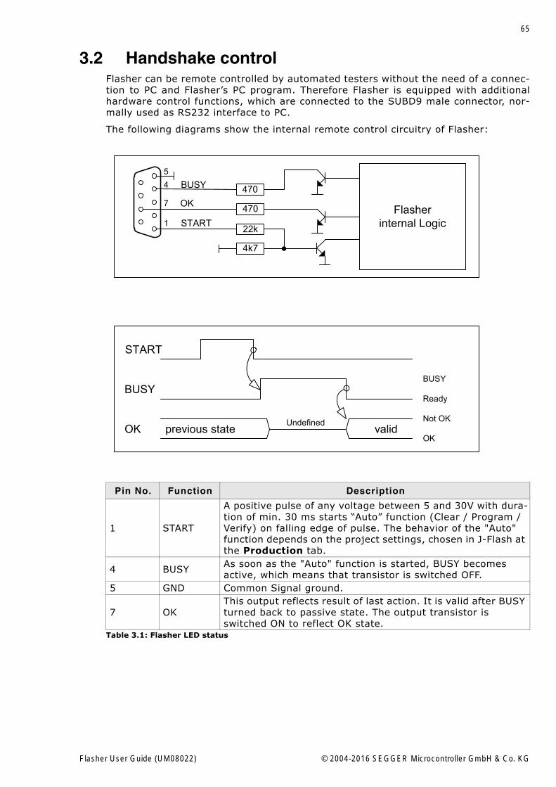
65
3.2 Handshake controlFlasher can be remote controlled by automated testers without the need of a connec-tion to PC and Flasher�s PC program. Therefore Flasher is equipped with additionalhardware control functions, which are connected to the SUBD9 male connector, nor-mally used as RS232 interface to PC.
The following diagrams show the internal remote control circuitry of Flasher:
Pin No. Function Description
1 START
A positive pulse of any voltage between 5 and 30V with dura-tion of min. 30 ms starts �Auto� function (Clear / Program / Verify) on falling edge of pulse. The behavior of the "Auto" function depends on the project settings, chosen in J-Flash at the Production tab.
4 BUSY As soon as the "Auto" function is started, BUSY becomes active, which means that transistor is switched OFF.
5 GND Common Signal ground.
7 OKThis output reflects result of last action. It is valid after BUSY turned back to passive state. The output transistor is switched ON to reflect OK state.
Table 3.1: Flasher LED status
470
470
22k
4k7
BUSY
OK
STARTFlasher
internal Logic1
4
7
5
START
BUSY
OK previous state validOK
Not OK
Ready
BUSY
Undefined
Flasher User Guide (UM08022) © 2004-2016 SEGGER Microcontroller GmbH & Co. KG
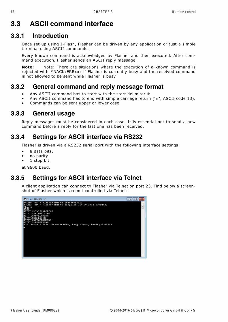
66 CHAPTER 3 Remote control
3.3 ASCII command interface
3.3.1 IntroductionOnce set up using J-Flash, Flasher can be driven by any application or just a simpleterminal using ASCII commands.
Every known command is acknowledged by Flasher and then executed. After com-mand execution, Flasher sends an ASCII reply message.
Note: Note: There are situations where the execution of a known command isrejected with #NACK:ERRxxx if Flasher is currently busy and the received commandis not allowed to be sent while Flasher is busy
3.3.2 General command and reply message format� Any ASCII command has to start with the start delimiter #.� Any ASCII command has to end with simple carriage return ('\r', ASCII code 13).� Commands can be sent upper or lower case
3.3.3 General usageReply messages must be considered in each case. It is essential not to send a newcommand before a reply for the last one has been received.
3.3.4 Settings for ASCII interface via RS232Flasher is driven via a RS232 serial port with the following interface settings:
� 8 data bits,� no parity� 1 stop bit
at 9600 baud.
3.3.5 Settings for ASCII interface via TelnetA client application can connect to Flasher via Telnet on port 23. Find below a screen-shot of Flasher which is remot controlled via Telnet:
Flasher User Guide (UM08022) © 2004-2016 SEGGER Microcontroller GmbH & Co. KG
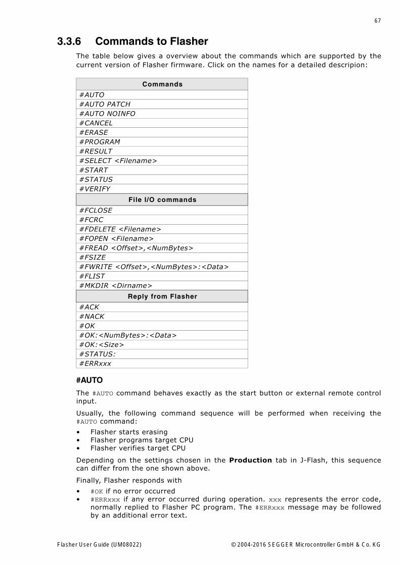
67
3.3.6 Commands to FlasherThe table below gives a overview about the commands which are supported by thecurrent version of Flasher firmware. Click on the names for a detailed descripion:
#AUTO
The #AUTO command behaves exactly as the start button or external remote controlinput.
Usually, the following command sequence will be performed when receiving the#AUTO command:
� Flasher starts erasing� Flasher programs target CPU� Flasher verifies target CPU
Depending on the settings chosen in the Production tab in J-Flash, this sequencecan differ from the one shown above.
Finally, Flasher responds with
� #OK if no error occurred� #ERRxxx if any error occurred during operation. xxx represents the error code,
normally replied to Flasher PC program. The #ERRxxx message may be followedby an additional error text.
Commands
#AUTO#AUTO PATCH#AUTO NOINFO#CANCEL#ERASE#PROGRAM#RESULT#SELECT <Filename>#START#STATUS#VERIFY
File I/O commands
#FCLOSE#FCRC#FDELETE <Filename>#FOPEN <Filename>#FREAD <Offset>,<NumBytes>#FSIZE#FWRITE <Offset>,<NumBytes>:<Data>#FLIST#MKDIR <Dirname>
Reply from Flasher
#ACK#NACK#OK#OK:<NumBytes>:<Data>#OK:<Size>#STATUS:#ERRxxx
Flasher User Guide (UM08022) © 2004-2016 SEGGER Microcontroller GmbH & Co. KG
68 CHAPTER 3 Remote control
During execution of the #AUTO command, Flasher automatically sends �status� mes-sages via RS232 to reflect the state of execution. Typically during execution of #AUTOcommand, Flasher will reply the following sequence of messages:
#ACK#STATUS:INITIALIZING#STATUS:CONNECTING#STATUS:UNLOCKING#STATUS:ERASING#STATUS:PROGRAMMING#STATUS:VERIFYING#OK (Total 13.993s, Erase 0.483s, Prog 9.183s, Verify 2.514s)
#AUTO PATCH
The #AUTO PATCH command allows to patch the content of the data to be pro-grammed.
Flasher responds with
� #OK if no error occurred� #ERRxxx if any error occurred during operation. xxx represents the error code,
normally replied to Flasher PC program. The #ERRxxx message may be followedby an additional error text.
For further information about the usage of the #AUTO PATCH command please refer toPatch file support on page 51.
#AUTO NOINFO
This command may be used instead of #AUTO, if no status messages from Flashershould be sent during execution. The NOINFO extension is also available for all othercommands.
The command ends with #OK or #ERRxxx
#BAUDRATE<Baudrate>
This command can be sent in order to change the baudrate of the UART used for theASCII command interface communication. <Baudrate> is expected in decimal format.
If this command succeeds, Flasher responds with:
#ACK#OK
Otherwise it will respond with one of the following error messages:
#ERR255: Invalid parameters
or
#ERR255: Baudrate is not supported
Note: After sending the #BAUDRATE command you will first have to wait until theFlasher responds with the #OK message. It is recommended wait 5ms before sendingthe next command with the new baudrate in order to give the Flasher the time tochange the baudrate.
#CANCEL
This command can be sent to abort a running program. It may take a while until thecurrent program is actually canceled.
Flasher will respond with:
#ERR007:CANCELED.
#ERASE
This command can be sent to erase all selected target flash sectors.
Flasher will reply the following sequence of messages:
Flasher User Guide (UM08022) © 2004-2016 SEGGER Microcontroller GmbH & Co. KG
69
#ACK#STATUS:INITIALIZING#STATUS:CONNECTING#STATUS:UNLOCKING#STATUS:ERASING#OK (Total 0.893s, Erase 0.483s)
#PROGRAM
This command can be used instead of #AUTO to program a target without erasing thetarget before programming and without performing a final verification.
#RESULT
This command can be sent any time, even during other command execution. Flasherresponds with the last result of the previously executed command.
#SELECT <Filename>
The #SELECT command is used to select a specific config and data file pair whichshould be used by Flasher to program the target. <Filename> specifies the name offile pair without extensions (.CFG and .DAT) on the Flasher which should be selected.Flasher saves the selected config and data file in the FLASHER.INI file. So this selec-tion is remembered even between power-cycling Flasher.
This may be verfy helpful in cases where several config and data files are stored onFlasher. The user can easily switch between these config and data files without con-necting Flasher to a host.
If this command succeeds, Flasher responds with:
#ACK#OK
Find below a sample sequence which shows how to use the #SELECT command:
#SELECT ATSAM7_1 // ATSAM7_1.CFG and ATSAM7_1.DAT is selected#ACK#OK#AUTO // Start auto programming#ACK#STATUS:INITIALIZING#STATUS:CONNECTING#STATUS:UNLOCKING#STATUS:ERASING#STATUS:PROGRAMMING#STATUS:VERIFYING#OK (Total 8.416s, Erase 0.005s, Prog 6.845s, Verify 0.959s)
#SELECT ATSAM7_2 // ATSAM7_2.CFG and ATSAM7_2.DAT is selected#ACK#OK#AUTO // Start auto programming#ACK#STATUS:INITIALIZING#STATUS:CONNECTING#STATUS:UNLOCKING#STATUS:ERASING#STATUS:PROGRAMMING#STATUS:VERIFYING#OK (Total 8.632s, Erase 0.005s, Prog 7.051s, Verify 0.969s)
#START
This command can be sent to release Flasher�s target interface. All signals fromFlasher to target will be set into high-Z mode, reset of target will be released. It maybe used to start target application program.
Flasher will reply with the following sequence of messages:
Flasher User Guide (UM08022) © 2004-2016 SEGGER Microcontroller GmbH & Co. KG
70 CHAPTER 3 Remote control
#ACK#STATUS:INITIALIZING#STATUS:CONNECTING#OK (Total 1.148s)
#STATUS
This command can be sent any time, even during other command execution. Flasherresponds with its current state. All defined state messages are described under Replyfrom Flasher on page 72.
#VERIFY
This command can used to verify the target Flash content against the data stored inFlasher.
3.3.6.1 File I/O commandsThe ASCII interface of Flasher also supports file I/O operations via RS232. The fol-lowing file I/O commands are supported:
#FCLOSE
The #FCLOSE command closes the file on Flasher which was opened via #FOPEN. Afterthis command has been issued further file I/O operations except #FDELETE are notallowed until the #FOPEN command is send again.
A typical sequence when using the #FCLOSE command does look like as follows:
#FCLOSE#ACK#OK
Note: When using the #FCLOSE command a file has to be open (previouslyopened by #FOPEN). Otherwise Flasher will respond with the following if no file hasbeen opened:
#ACK#ERR255:No file opened
#FCRC
The #FCRC command calculates a 32-bit CRC of the given file. This CRC can be usedto verify file integrity. This command should not be used while a file has been openedvia #FOPEN. The CRC will be also reported by J-Flash when downloading or savingfiles via J-Flash.
A typical sequence when using the #FCRC command does look like as follows:
#FCRC flasher.dat#ACK#OK:0x75BC855A
#FDELETE <Filename>
The #FDELETE command is used to delete a file on Flasher where <Filename> speci-fies the name of the file.
A typical sequence when using the #FDELETE command does look like as follows:
#FDELETE flasher.dat#ACK#OK
Note: If deletion of the file fails for example if the file does not exist, Flasher willrespond with the following sequence:
#ACK#ERR255:Failed to delete file
Flasher User Guide (UM08022) © 2004-2016 SEGGER Microcontroller GmbH & Co. KG
71
#FOPEN <Filename>
The #FOPEN command is used to open a file on Flasher for further file I/O operations.<Filename> specifies the file on the Flasher which should be opened. If <Filename>can not be found on Flasher a new one will be created.
A typical sequence using the #FOPEN command does look like as follows:
#FOPEN flasher.dat#ACK#OK
Note: Currently only one file can be open at the same time. If #FOPEN is sendand another file is already open, Flasher will respond with:
#ACK#ERR255:A file has already been opened
#FREAD <Offset>,<NumBytes>
The #FREAD command is used to read data from a file on Flasher. <Offset> specifiesthe offset in the file, at which data reading is started. <NumBytes> specifies the num-ber of bytes which should be read.
A typical sequence when using the #FREAD command does look like as follows:
#FREAD 0,4#ACK#OK:04:466c6173
If the #FREAD command succeeds, Flasher will finally respond with a #OK:<Num-Bytes>:<Data> reply message. For more information about the Flasher reply mes-sages, please refer to Reply from Flasher on page 72.
Note: In order to use the #FREAD command. A file has to be opened before, viathe #FOPEN command. Otherwise Flasher will respond with the following sequence:
#ACK#ERR255:No file opened
#FSIZE
The #FSIZE command is used to get the size of the currently opened file on Flasher.
A typical sequence when using the #FSIZE command does look like as follows:
#FSIZE#ACK#OK:10 // file on flasher which is currently open, has a size of 16 bytes
If the #FSIZE command succeeds, Flasher will respond with a #OK:<Size> reply mes-sage. For more information about the Flasher reply messages, please refer to Replyfrom Flasher on page 72.
Note: In order to use the #FREAD command. A file has to be opened before, viathe #FOPEN command. Otherwise Flasher will respond with the following sequence:
#ACK#ERR255:No file opened
#FWRITE <Offset>,<NumBytes>:<Data>
The #FWRITE command is used to write to a file on Flasher. <Offset> specifies theoffset in the file, at which data writing is started. <NumBytes> specifies the number ofbytes which are send with this command and which are written into the file onFlasher. <NumBytes> is limited to 512 bytes at once. This means, if you want to writee.g. 1024 bytes, you have to send the #FWRITE command twice, using an appropriateoffset when sending it the second time.
<Offset> and <NumBytes> are expected in hexadecimal format.
Flasher User Guide (UM08022) © 2004-2016 SEGGER Microcontroller GmbH & Co. KG
72 CHAPTER 3 Remote control
#FWRITE 0,200:<Data>#FWRITE 200,200:<Data>
The data is expected in hexadecimal format (two hexadecimal characters per byte).The following example illustrates the use of #FWRITE:
Data to be send: Hello !ASCII values: 0x48, 0x65, 0x6C, 0x6C, 0x6F, 0x20, 0x21
#FWRITE 0,7:48656C6C6F2021
Note: In order to use the #FWRITE command a file has to be opened via the#FOPEN command, first. Otherwise Flasher will respond with the following sequence:
#ACK#ERR255:No file opened
#FLIST
The #LIST command is used to list all files stored on the Flasher.
A typical sequence using the #FLIST command does look like as follows:
#FLIST#ACKFLASHER.INI Size: 60SERIAL.TXT Size: 3FLASHER.LOG Size: 207FOLDER (DIR)FOLDER\TEST1.CFG Size: 2048FOLDER\TEST1.DAT Size: 12288#OK
#MKDIR <Dirname>
The #MKDIR command is used to create a directory on Flasher. <Dirname> specifiesthe name of the new directory. <Dirname> may also specify a path to create a subdi-rectoriy.
A typical sequence using the #MKDIR command does look like as follows:
#MKDIR folder#ACK#OK
Note: If the directory can not be created because of a bad <Dirname> argument,Flasher will respond with:
#ACK#ERR255:Failed to create directory
3.3.7 Reply from FlasherThe reply messages from Flasher follow the same data format as commands. Anyreply message starts with ASCII start delimiter #, ends with simple carriage return(ASCII code 13) and is sent in uppercase. In contrast to commands, replies can befollowed by a description message, which gives more detailed information about thereply. This description is sent in mixed case. The #OK reply, for example, is such areply. It is followed by a string containing information about the performance timeneeded for the operations:
#OK (Total 13.993s, Erase 0.483s, Prog 9.183s, Verify 2.514s)
The following reply messages from Flasher are defined:
#ACK
Flasher replies with #ACK message on reception of any defined command before thecommand itself is executed.
Flasher User Guide (UM08022) © 2004-2016 SEGGER Microcontroller GmbH & Co. KG
73
#NACK
Flasher replies with #NACK, if an undefined command was received.
#OK
Flasher replies with #OK, if a command other than #STATUS or #RESULT was executedand ended with no error.
#OK:<NumBytes>:<Data>
Flasher replies with #OK:<Len>:<Data> if a #FREAD command was executed. <Num-Bytes> is the number of bytes which could be read. This value may differ from thenumber of requested bytes, for example if more bytes than available, wererequested. <NumBytes> and <Data> are send in hexadecimal format (for <Data>: twohexadecimal characters per byte).
#OK:<Size>
Flasher replies if #OK:<Size> if a #FSIZE command has been executed. <Size> is thesize (in bytes) of the currently opened file. <Size> is send in hexadecimal format.
#STATUS:
Flasher replies with its current state.
The following status messages are currently defined:
Message Description
#STATUS:READYFlasher is ready to receive a new command.
#STATUS:CONNECTINGFlasher initializes connection to tar-get CPU.
#STATUS:INITIALIZINGFlasher performs self check and internal init.
#STATUS:UNLOCKING Unlocking flash sectors.
#STATUS:ERASINGFlasher is erasing the flash of the target device.
#STATUS:PROGRAMMINGFlasher is programming the flash of the target device.
#STATUS:VERIFYINGFlasher verifies the programmed flash contents.
Table 3.2: List of status messages that are currently defined
Flasher User Guide (UM08022) © 2004-2016 SEGGER Microcontroller GmbH & Co. KG
74 CHAPTER 3 Remote control
#ERRxxx
If any command other than #STATUS or #RESULT was terminated with an error,Flasher cancels the command and replies with an error message instead of #OK mes-sage.
Some error codes may be followed by colon and an additional error text.
For example:
#ERR007:CANCELED.
The error code numbers are described in the following table:
Message Description
#ERR007Flasher received #CANCEL command and has canceled the current opera-tion.
#ERR008Flasher is already busy with execu-tion of previous command.
#ERR009 Failed to allocate memory.#ERR010 Failed to open file.#ERR011 Failed to read file.#ERR012 Failed to write file.#ERR013 Failed to delete file.
#ERR255Undefined error occurred. This reply is followed by an error string.
Table 3.3: List of error code numbers which are currently defined
Flasher User Guide (UM08022) © 2004-2016 SEGGER Microcontroller GmbH & Co. KG
75
Chapter 4
Performance
The following chapter lists programming performance of common flash devices andmicrocontrollers.
Flasher User Guide (UM08022) © 2004-2016 SEGGER Microcontroller GmbH & Co. KG
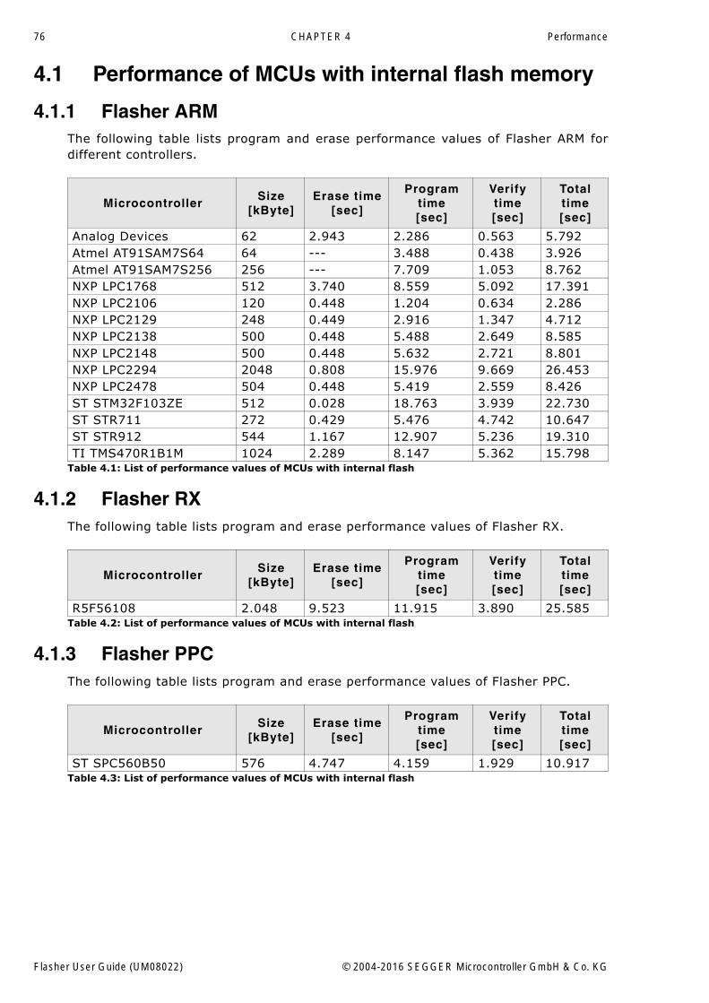
76 CHAPTER 4 Performance
4.1 Performance of MCUs with internal flash memory
4.1.1 Flasher ARMThe following table lists program and erase performance values of Flasher ARM fordifferent controllers.
4.1.2 Flasher RXThe following table lists program and erase performance values of Flasher RX.
4.1.3 Flasher PPCThe following table lists program and erase performance values of Flasher PPC.
MicrocontrollerSize
[kByte]Erase time
[sec]
Programtime[sec]
Verifytime[sec]
Total time [sec]
Analog Devices 62 2.943 2.286 0.563 5.792Atmel AT91SAM7S64 64 --- 3.488 0.438 3.926Atmel AT91SAM7S256 256 --- 7.709 1.053 8.762NXP LPC1768 512 3.740 8.559 5.092 17.391NXP LPC2106 120 0.448 1.204 0.634 2.286NXP LPC2129 248 0.449 2.916 1.347 4.712NXP LPC2138 500 0.448 5.488 2.649 8.585NXP LPC2148 500 0.448 5.632 2.721 8.801NXP LPC2294 2048 0.808 15.976 9.669 26.453NXP LPC2478 504 0.448 5.419 2.559 8.426ST STM32F103ZE 512 0.028 18.763 3.939 22.730ST STR711 272 0.429 5.476 4.742 10.647ST STR912 544 1.167 12.907 5.236 19.310TI TMS470R1B1M 1024 2.289 8.147 5.362 15.798
Table 4.1: List of performance values of MCUs with internal flash
MicrocontrollerSize
[kByte]Erase time
[sec]
Programtime[sec]
Verifytime[sec]
Total time [sec]
R5F56108 2.048 9.523 11.915 3.890 25.585Table 4.2: List of performance values of MCUs with internal flash
MicrocontrollerSize
[kByte]Erase time
[sec]
Programtime[sec]
Verifytime[sec]
Total time [sec]
ST SPC560B50 576 4.747 4.159 1.929 10.917Table 4.3: List of performance values of MCUs with internal flash
Flasher User Guide (UM08022) © 2004-2016 SEGGER Microcontroller GmbH & Co. KG
77
Chapter 5
Hardware
This chapter gives an overview about Flasher specific hardware details, such as thepinouts and available adapters.
Flasher User Guide (UM08022) © 2004-2016 SEGGER Microcontroller GmbH & Co. KG
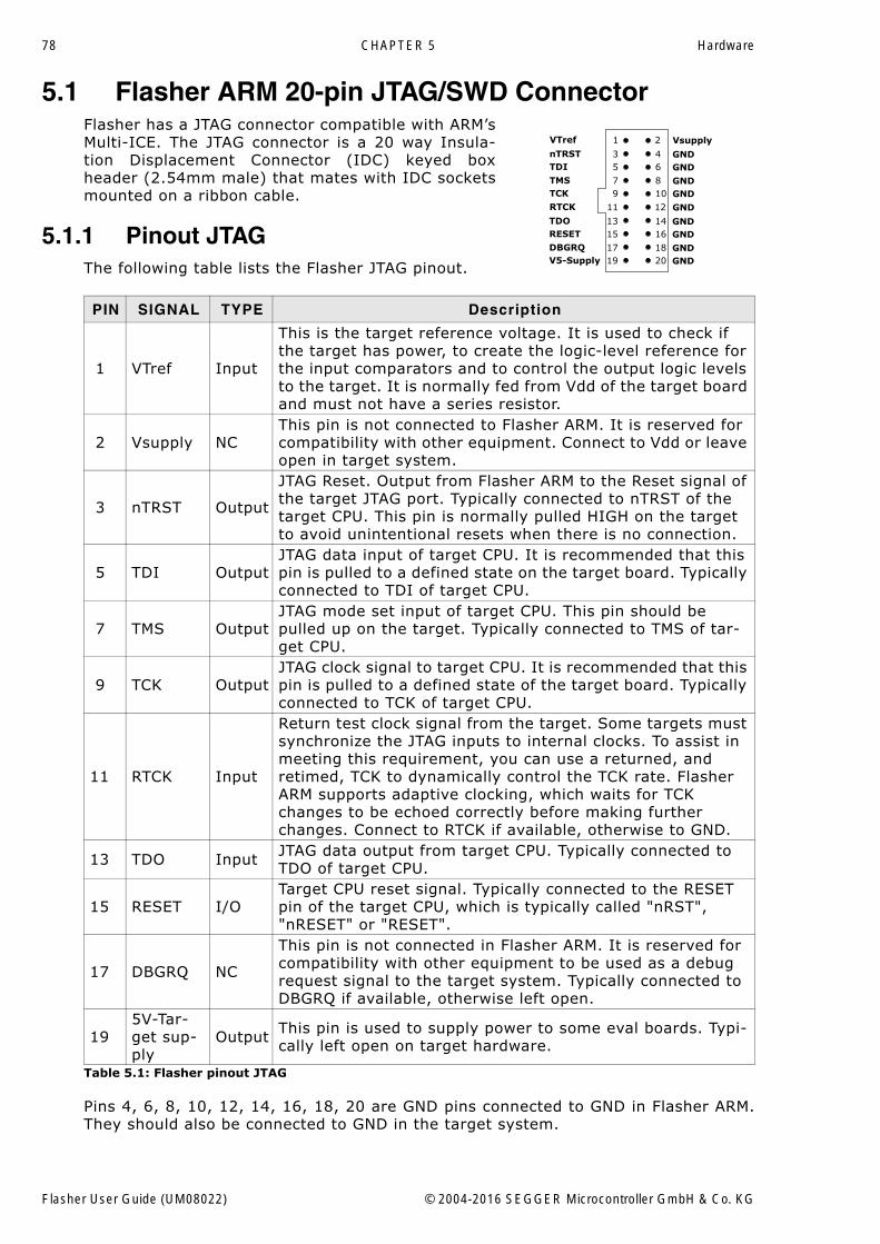
78 CHAPTER 5 Hardware
5.1 Flasher ARM 20-pin JTAG/SWD ConnectorFlasher has a JTAG connector compatible with ARM�sMulti-ICE. The JTAG connector is a 20 way Insula-tion Displacement Connector (IDC) keyed boxheader (2.54mm male) that mates with IDC socketsmounted on a ribbon cable.
5.1.1 Pinout JTAGThe following table lists the Flasher JTAG pinout.
Pins 4, 6, 8, 10, 12, 14, 16, 18, 20 are GND pins connected to GND in Flasher ARM.They should also be connected to GND in the target system.
PIN SIGNAL TYPE Description
1 VTref Input
This is the target reference voltage. It is used to check if the target has power, to create the logic-level reference for the input comparators and to control the output logic levels to the target. It is normally fed from Vdd of the target board and must not have a series resistor.
2 Vsupply NCThis pin is not connected to Flasher ARM. It is reserved for compatibility with other equipment. Connect to Vdd or leave open in target system.
3 nTRST Output
JTAG Reset. Output from Flasher ARM to the Reset signal of the target JTAG port. Typically connected to nTRST of the target CPU. This pin is normally pulled HIGH on the target to avoid unintentional resets when there is no connection.
5 TDI OutputJTAG data input of target CPU. It is recommended that this pin is pulled to a defined state on the target board. Typically connected to TDI of target CPU.
7 TMS OutputJTAG mode set input of target CPU. This pin should be pulled up on the target. Typically connected to TMS of tar-get CPU.
9 TCK OutputJTAG clock signal to target CPU. It is recommended that this pin is pulled to a defined state of the target board. Typically connected to TCK of target CPU.
11 RTCK Input
Return test clock signal from the target. Some targets must synchronize the JTAG inputs to internal clocks. To assist in meeting this requirement, you can use a returned, and retimed, TCK to dynamically control the TCK rate. Flasher ARM supports adaptive clocking, which waits for TCK changes to be echoed correctly before making further changes. Connect to RTCK if available, otherwise to GND.
13 TDO Input JTAG data output from target CPU. Typically connected to TDO of target CPU.
15 RESET I/OTarget CPU reset signal. Typically connected to the RESET pin of the target CPU, which is typically called "nRST", "nRESET" or "RESET".
17 DBGRQ NC
This pin is not connected in Flasher ARM. It is reserved for compatibility with other equipment to be used as a debug request signal to the target system. Typically connected to DBGRQ if available, otherwise left open.
195V-Tar-get sup-ply
Output This pin is used to supply power to some eval boards. Typi-cally left open on target hardware.
Table 5.1: Flasher pinout JTAG
1 2
3 45 6
7 89 10
11 12
13 1415 16
17 1819 20
VTref
nTRSTTDI
TMSTCK
RTCK
TDORESET
DBGRQV5-Supply
Vsupply
GND
GNDGND
GND
GNDGND
GNDGND
GND
Flasher User Guide (UM08022) © 2004-2016 SEGGER Microcontroller GmbH & Co. KG
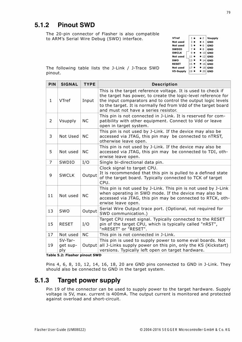
79
5.1.2 Pinout SWDThe 20-pin connector of Flasher is also compatibleto ARM�s Serial Wire Debug (SWD) interface.
The following table lists the J-Link / J-Trace SWDpinout.
Pins 4, 6, 8, 10, 12, 14, 16, 18, 20 are GND pins connected to GND in J-Link. Theyshould also be connected to GND in the target system.
5.1.3 Target power supplyPin 19 of the connector can be used to supply power to the target hardware. Supplyvoltage is 5V, max. current is 400mA. The output current is monitored and protectedagainst overload and short-circuit.
PIN SIGNAL TYPE Description
1 VTref Input
This is the target reference voltage. It is used to check if the target has power, to create the logic-level reference for the input comparators and to control the output logic levels to the target. It is normally fed from Vdd of the target board and must not have a series resistor.
2 Vsupply NCThis pin is not connected in J-Link. It is reserved for com-patibility with other equipment. Connect to Vdd or leave open in target system.
3 Not Used NCThis pin is not used by J-Link. If the device may also be accessed via JTAG, this pin may be connected to nTRST, otherwise leave open.
5 Not used NCThis pin is not used by J-Link. If the device may also be accessed via JTAG, this pin may be connected to TDI, oth-erwise leave open.
7 SWDIO I/O Single bi-directional data pin.
9 SWCLK Output
Clock signal to target CPU.It is recommended that this pin is pulled to a defined state of the target board. Typically connected to TCK of target CPU.
11 Not used NC
This pin is not used by J-Link. This pin is not used by J-Link when operating in SWD mode. If the device may also be accessed via JTAG, this pin may be connected to RTCK, oth-erwise leave open.
13 SWO Output Serial Wire Output trace port. (Optional, not required for SWD communication.)
15 RESET I/OTarget CPU reset signal. Typically connected to the RESET pin of the target CPU, which is typically called "nRST", "nRESET" or "RESET".
17 Not used NC This pin is not connected in J-Link.
195V-Tar-get sup-ply
OutputThis pin is used to supply power to some eval boards. Not all J-Links supply power on this pin, only the KS (Kickstart) versions. Typically left open on target hardware.
Table 5.2: Flasher pinout SWD
1 2
3 45 6
7 89 10
11 12
13 1415 16
17 1819 20
VTref
Not usedNot used
SWDIOSWCLK
Not used
SWORESET
Not usedV5-Supply
Vsupply
GND
GNDGND
GND
GNDGND
GNDGND
GND
Flasher User Guide (UM08022) © 2004-2016 SEGGER Microcontroller GmbH & Co. KG

80 CHAPTER 5 Hardware
Power can be controlled via the J-Link commander. The following commands areavailable to control power:
Command Explanation
power on Switch target power onpower off Switch target power offpower on perm Set target power supply default to "on"power off perm Set target power supply default to "off"
Table 5.3: Command List
Flasher User Guide (UM08022) © 2004-2016 SEGGER Microcontroller GmbH & Co. KG
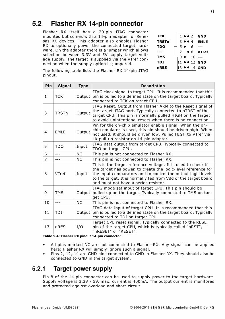
81
5.2 Flasher RX 14-pin connectorFlasher RX itself has a 20-pin JTAG connectormounted but comes with a 14-pin adapter for Rene-sas RX devices. This adapter also enables FlasherRX to optionally power the connected target hard-ware. On the adapter there is a jumper which allowsselection between 3.3V and 5V supply target volt-age supply. The target is supplied via the VTref con-nection when the supply option is jumpered.
The following table lists the Flasher RX 14-pin JTAGpinout.
� All pins marked NC are not connected to Flasher RX. Any signal can be appliedhere; Flasher RX will simply ignore such a signal.
� Pins 2, 12, 14 are GND pins connected to GND in Flasher RX. They should also beconnected to GND in the target system.
5.2.1 Target power supplyPin 8 of the 14-pin connector can be used to supply power to the target hardware.Supply voltage is 3.3V / 5V, max. current is 400mA. The output current is monitoredand protected against overload and short-circuit.
Pin Signal Type Description
1 TCK OutputJTAG clock signal to target CPU. It is recommended that this pin is pulled to a defined state on the target board. Typically connected to TCK on target CPU.
3 TRSTn Output
JTAG Reset. Output from Flasher ARM to the Reset signal of the target JTAG port. Typically connected to nTRST of the target CPU. This pin is normally pulled HIGH on the target to avoid unintentional resets when there is no connection.
4 EMLE Output
Pin for the on-chip emulator enable signal. When the on-chip emulator is used, this pin should be driven high. When not used, it should be driven low. Pulled HIGH to VTref via 1k pull-up resistor on 14-pin adapter.
5 TDO Input JTAG data output from target CPU. Typically connected to TDO on target CPU.
6 --- NC This pin is not connected to Flasher RX.7 --- NC This pin is not connected to Flasher RX.
8 VTref Input
This is the target reference voltage. It is used to check if the target has power, to create the logic-level reference for the input comparators and to control the output logic levels to the target. It is normally fed from Vdd of the target board and must not have a series resistor.
9 TMS OutputJTAG mode set input of target CPU. This pin should be pulled up on the target. Typically connected to TMS on tar-get CPU.
10 --- NC This pin is not connected to Flasher RX.
11 TDI OutputJTAG data input of target CPU. It is recommended that this pin is pulled to a defined state on the target board. Typically connected to TDI on target CPU.
13 nRES I/OTarget CPU reset signal. Typically connected to the RESET pin of the target CPU, which is typically called "nRST", "nRESET" or "RESET".
Table 5.4: Flasher RX pinout 14-pin connector
1 2
3 45 6
7 89 10
11 12
13 14
TCK
TRSTnTDO
---TMS
TDI
nRES
GND
---
VTref---
GND
GND
EMLE
Flasher User Guide (UM08022) © 2004-2016 SEGGER Microcontroller GmbH & Co. KG
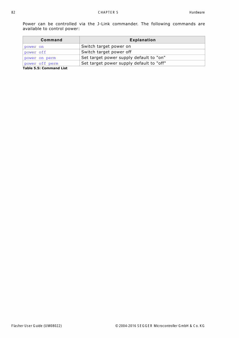
82 CHAPTER 5 Hardware
Power can be controlled via the J-Link commander. The following commands areavailable to control power:
Command Explanation
power on Switch target power onpower off Switch target power offpower on perm Set target power supply default to "on"power off perm Set target power supply default to "off"
Table 5.5: Command List
Flasher User Guide (UM08022) © 2004-2016 SEGGER Microcontroller GmbH & Co. KG
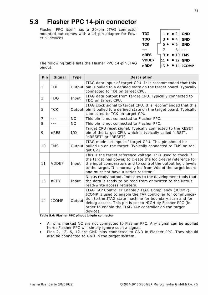
83
5.3 Flasher PPC 14-pin connectorFlasher PPC itself has a 20-pin JTAG connectormounted but comes with a 14-pin adapter for Pow-erPC devices.
The following table lists the Flasher PPC 14-pin JTAGpinout.
� All pins marked NC are not connected to Flasher PPC. Any signal can be appliedhere; Flasher PPC will simply ignore such a signal.
� Pins 2, 12, 6, 12 are GND pins connected to GND in Flasher PPC. They shouldalso be connected to GND in the target system.
Pin Signal Type Description
1 TDI OutputJTAG data input of target CPU. It is recommended that this pin is pulled to a defined state on the target board. Typically connected to TDI on target CPU.
3 TDO Input JTAG data output from target CPU. Typically connected to TDO on target CPU.
5 TCK OutputJTAG clock signal to target CPU. It is recommended that this pin is pulled to a defined state on the target board. Typically connected to TCK on target CPU.
7 --- NC This pin is not connected to Flasher PPC.8 --- NC This pin is not connected to Flasher PPC.
9 nRES I/OTarget CPU reset signal. Typically connected to the RESET pin of the target CPU, which is typically called "nRST", "nRESET" or "RESET".
10 TMS OutputJTAG mode set input of target CPU. This pin should be pulled up on the target. Typically connected to TMS on tar-get CPU.
11 VDDE7 Input
This is the target reference voltage. It is used to check if the target has power, to create the logic-level reference for the input comparators and to control the output logic levels to the target. It is normally fed from Vdd of the target board and must not have a series resistor.
13 nRDY InputNexus ready output. Indicates to the development tools that the data is ready to be read from or written to the Nexus read/write access registers.
14 JCOMP Output
JTAG TAP Controller Enable / JTAG Compliancy (JCOMP). JCOMP is used to enable the TAP controller for communica-tion to the JTAG state machine for boundary scan and for debug access. This pin is set to HIGH by Flasher PPC (in order to enable the JTAG TAP controller on the target device).
Table 5.6: Flasher PPC pinout 14-pin connector
1 2
3 45 6
7 89 10
11 12
13 14
TDI
TDOTCK
---nRES
VDDE7
nRDY
GND
GND
---TMS
GND
JCOMP
GND
Flasher User Guide (UM08022) © 2004-2016 SEGGER Microcontroller GmbH & Co. KG
84 CHAPTER 5 Hardware
5.4 Target board designWe strongly advise following the recommendations given by the chip manufacturer.These recommendations are normally in line with the recommendations. Please referto the the appropriate tables depending on the core:
� Pinout JTAG on page 78� Pinout SWD on page 79� Flasher RX 14-pin connector on page 81� Flasher PPC 14-pin connector on page 83
In case of doubt you should follow the recommendations given by the semiconductormanufacturer.
5.4.1 Pull-up/pull-down resistorsUnless otherwise specified by developer�s manual, pull-ups/pull-downs are recom-mended to be between 2.2 kOhms and 47 kOhms.
5.4.2 RESET, nTRSTThe debug logic is reset independently from the CPU core with nTRST. For the core tooperate correctly it is essential that both signals are asserted after power-up.
The advantage of having separate connection to the two reset signals is that it allowsthe developer performing software debug to setup breakpoints, which are retained bythe debug logic even when the core is reset. (For example, at the reset vectoraddress, to allow the code to be single-stepped as soon as it comes out of reset).This can be particularly useful when first trying to bring up a board with a new ASIC.
Flasher User Guide (UM08022) © 2004-2016 SEGGER Microcontroller GmbH & Co. KG
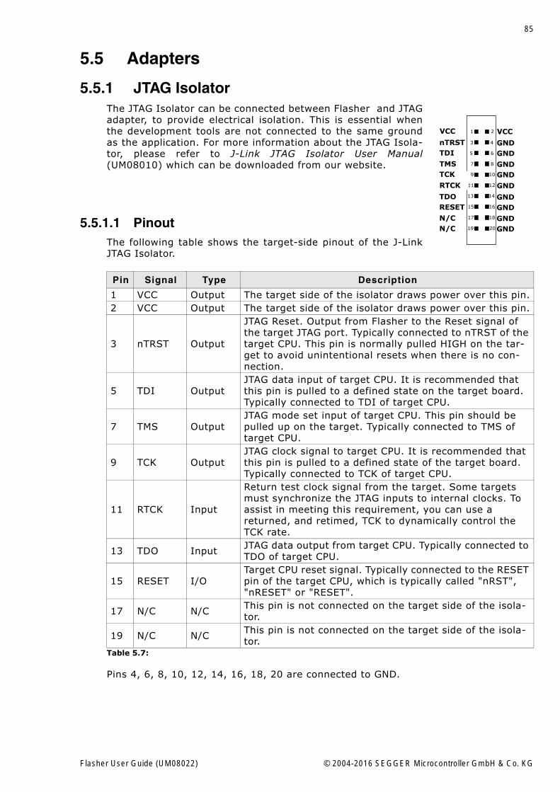
85
5.5 Adapters
5.5.1 JTAG IsolatorThe JTAG Isolator can be connected between Flasher and JTAGadapter, to provide electrical isolation. This is essential whenthe development tools are not connected to the same groundas the application. For more information about the JTAG Isola-tor, please refer to J-Link JTAG Isolator User Manual(UM08010) which can be downloaded from our website.
5.5.1.1 PinoutThe following table shows the target-side pinout of the J-LinkJTAG Isolator.
Pins 4, 6, 8, 10, 12, 14, 16, 18, 20 are connected to GND.
Pin Signal Type Description
1 VCC Output The target side of the isolator draws power over this pin.2 VCC Output The target side of the isolator draws power over this pin.
3 nTRST Output
JTAG Reset. Output from Flasher to the Reset signal of the target JTAG port. Typically connected to nTRST of the target CPU. This pin is normally pulled HIGH on the tar-get to avoid unintentional resets when there is no con-nection.
5 TDI OutputJTAG data input of target CPU. It is recommended that this pin is pulled to a defined state on the target board. Typically connected to TDI of target CPU.
7 TMS OutputJTAG mode set input of target CPU. This pin should be pulled up on the target. Typically connected to TMS of target CPU.
9 TCK OutputJTAG clock signal to target CPU. It is recommended that this pin is pulled to a defined state of the target board. Typically connected to TCK of target CPU.
11 RTCK Input
Return test clock signal from the target. Some targets must synchronize the JTAG inputs to internal clocks. To assist in meeting this requirement, you can use a returned, and retimed, TCK to dynamically control the TCK rate.
13 TDO Input JTAG data output from target CPU. Typically connected to TDO of target CPU.
15 RESET I/OTarget CPU reset signal. Typically connected to the RESET pin of the target CPU, which is typically called "nRST", "nRESET" or "RESET".
17 N/C N/C This pin is not connected on the target side of the isola-tor.
19 N/C N/C This pin is not connected on the target side of the isola-tor.
Table 5.7:
1
3
5
7
9
11
13
15
17
19
VCC
nTRSTTDI
TMSTCK
RTCK
TDORESET
N/CN/C
VCC
GND
GNDGND
GND
GNDGND
GNDGND
GND
2
4
6
8
10
12
14
16
18
20
Flasher User Guide (UM08022) © 2004-2016 SEGGER Microcontroller GmbH & Co. KG
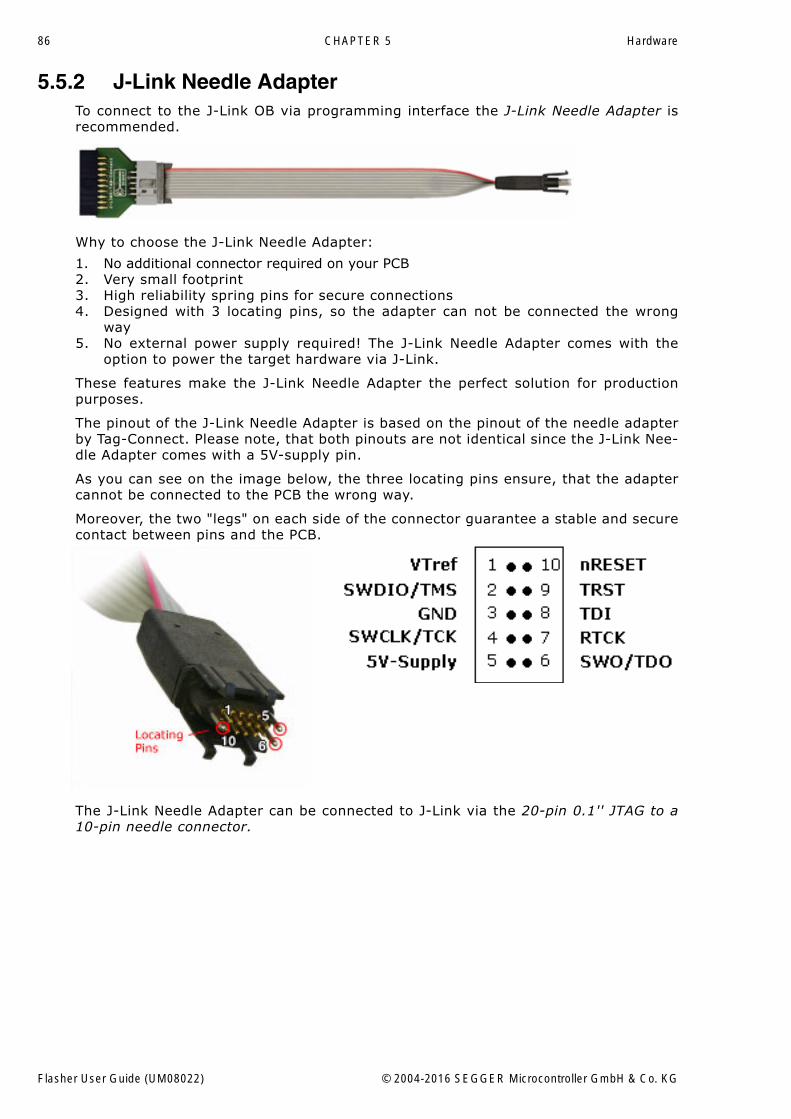
86 CHAPTER 5 Hardware
5.5.2 J-Link Needle AdapterTo connect to the J-Link OB via programming interface the J-Link Needle Adapter isrecommended.
Why to choose the J-Link Needle Adapter:
1. No additional connector required on your PCB2. Very small footprint3. High reliability spring pins for secure connections4. Designed with 3 locating pins, so the adapter can not be connected the wrong
way5. No external power supply required! The J-Link Needle Adapter comes with the
option to power the target hardware via J-Link.
These features make the J-Link Needle Adapter the perfect solution for productionpurposes.
The pinout of the J-Link Needle Adapter is based on the pinout of the needle adapterby Tag-Connect. Please note, that both pinouts are not identical since the J-Link Nee-dle Adapter comes with a 5V-supply pin.
As you can see on the image below, the three locating pins ensure, that the adaptercannot be connected to the PCB the wrong way.
Moreover, the two "legs" on each side of the connector guarantee a stable and securecontact between pins and the PCB.
The J-Link Needle Adapter can be connected to J-Link via the 20-pin 0.1'' JTAG to a10-pin needle connector.
Flasher User Guide (UM08022) © 2004-2016 SEGGER Microcontroller GmbH & Co. KG
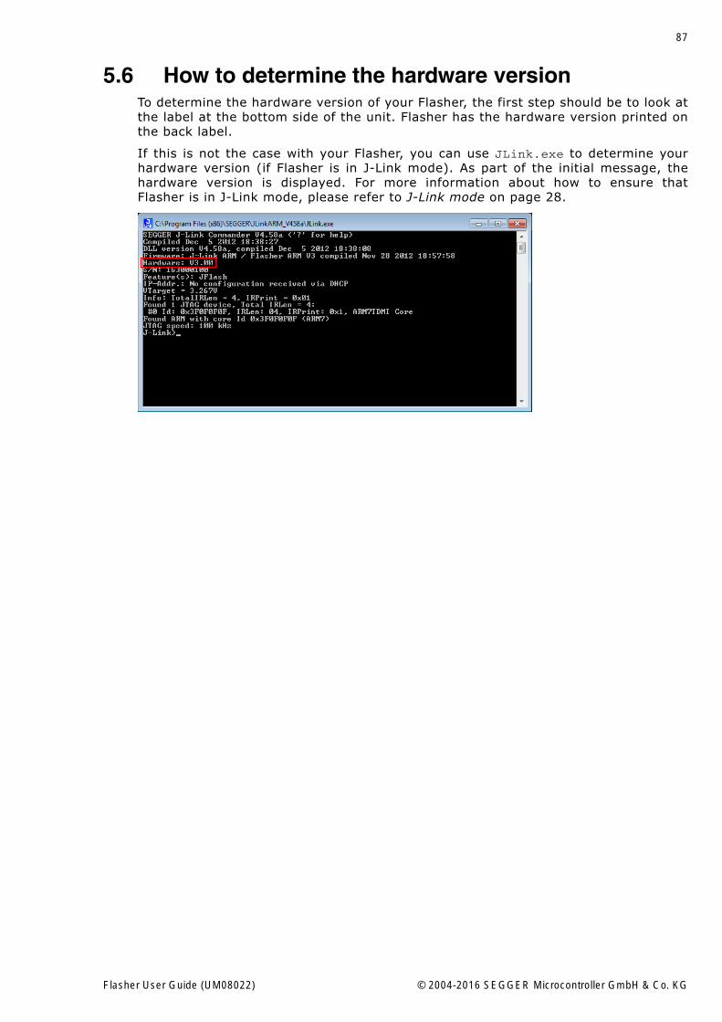
87
5.6 How to determine the hardware versionTo determine the hardware version of your Flasher, the first step should be to look atthe label at the bottom side of the unit. Flasher has the hardware version printed onthe back label.
If this is not the case with your Flasher, you can use JLink.exe to determine yourhardware version (if Flasher is in J-Link mode). As part of the initial message, thehardware version is displayed. For more information about how to ensure thatFlasher is in J-Link mode, please refer to J-Link mode on page 28.
Flasher User Guide (UM08022) © 2004-2016 SEGGER Microcontroller GmbH & Co. KG
88 CHAPTER 5 Hardware
Flasher User Guide (UM08022) © 2004-2016 SEGGER Microcontroller GmbH & Co. KG
89
Chapter 6
Support and FAQs
This chapter contains troubleshooting tips together with solutions for common prob-lems which might occur when using Flasher. There are several steps you can takebefore contacting support. Performing these steps can solve many problems andoften eliminates the need for assistance. This chapter also contains a collection offrequently asked questions (FAQs) with answers.
Flasher User Guide (UM08022) © 2004-2016 SEGGER Microcontroller GmbH & Co. KG
90 CHAPTER 6 Support and FAQs
6.1 Contacting supportBefore contacting support, make sure you tried to solve your problem by trying yourFlasher with another PC and if possible with another target system to see if it worksthere. If the device functions correctly, the USB setup on the original machine oryour target hardware is the source of the problem, not Flasher.
If you need to contact support, send the following information to [email protected]
� A detailed description of the problem� Flasher serial number� Information about your target hardware (processor, board, etc.).� FLASHER.CFG, FLASHER.DAT, FLASHER.LOG, SERIAL.TXT file from Flasher. To get
these files, Flasher has to be in MSD mode. For more information about how toboot Flasher in MSD mode, please refer to MSD mode on page 31.
Flasher is sold directly by SEGGER.
Flasher User Guide (UM08022) © 2004-2016 SEGGER Microcontroller GmbH & Co. KG
91
6.2 Frequently Asked QuestionsMaximum JTAG speed
Q: What is the maximum JTAG speed supported by Flasher?A: Flasher�s maximum supported JTAG speed is 12MHz.
Maximum download speedQ: What is the maximum download speed?A: The maximum download speed is currently about 720 Kbytes/second when down-
loading into RAM. The actual speed depends on various factors, such as JTAG,clock speed, host CPU core etc.
Flasher User Guide (UM08022) © 2004-2016 SEGGER Microcontroller GmbH & Co. KG

92 CHAPTER 6 Support and FAQs
Flasher User Guide (UM08022) © 2004-2016 SEGGER Microcontroller GmbH & Co. KG
93
Chapter 7
Background information
This chapter provides background information about flash programming in general. Italso provides information about how to replace the firmware of Flasher manually.
Flasher User Guide (UM08022) © 2004-2016 SEGGER Microcontroller GmbH & Co. KG
94 CHAPTER 7 Background information
7.1 Flash programmingFlasher comes with a DLL, which allows - amongst other functionalities - reading andwriting RAM, CPU registers, starting and stopping the CPU, and setting breakpoints.
7.1.1 How does flash programming via Flasher work?This requires extra code. This extra code typically downloads a program into the RAMof the target system, which is able to erase and program the flash. This program iscalled RAM code and "knows" how to program the flash; it contains an implementa-tion of the flash programming algorithm for the particular flash. Different flash chipshave different programming algorithms; the programming algorithm also depends onother things, such as endianess of the target system and organization of the flashmemory (for example 1 * 8 bits, 1 * 16 bits, 2 * 16 bits or 32 bits). The RAM coderequires data to be programmed into the flash memory. The data is supplied bydownloading it to RAM.
7.1.2 Data download to RAMThe data (or part of it) is downloaded to another part of the RAM of the target sys-tem. The Instruction pointer (PC) of the CPU is then set to the start address of theRam code, the CPU is started, executing the RAM code. The RAM code, which con-tains the programming algorithm for the flash chip, copies the data into the flashchip. The CPU is stopped after this. This process may have to be repeated until theentire data is programmed into the flash.
7.1.3 Available options for flash programmingIn general, there are two possibilities in order to use Flasher for flash programming:
� Using Flasher stand-alone to program the target flash memory (stand-alonemode)
� Using Flasher in combination with J-Flash to program the target flash memory(Flasher in "J-Link mode")
7.1.3.1 Using Flasher in stand-alone modeIn order to use the Flasher in stand-alone mode, it has to be configured first. Formore information about how to setup Flasher for using in "stand-alone mode", pleaserefer to Setting up Flasher for stand-alone mode on page 32.
7.1.3.2 J-Flash - Complete flash programming solutionJ-Flash is a stand-alone Windows application, which can read / write data files andprogram the flash in almost any ARM system. For more information about J-Flashplease refer to the J-Flash User Guide, which can be downloaded from our websitehttp://www.segger.com.
7.1.4 How does the universal flash programming work?In universal flash programming mode, the flasher typically communicates with a bootloader running on the device using a vendor specific protocol, rather than using thedebug interface.
Universal flash programming is available only for stand-alone mode.
Flasher User Guide (UM08022) © 2004-2016 SEGGER Microcontroller GmbH & Co. KG
95
Chapter 8
Glossary
This chapter describes important terms used throughout this manual.
Flasher User Guide (UM08022) © 2004-2016 SEGGER Microcontroller GmbH & Co. KG
96 CHAPTER 8 Glossary
Big-endian
Memory organization where the least significant byte of a word is at a higher addressthan the most significant byte. See Little-endian.
Cache cleaning
The process of writing dirty data in a cache to main memory.
Coprocessor
An additional processor that is used for certain operations, for example, for floating-point math calculations, signal processing, or memory management.
Dirty data
When referring to a processor data cache, data that has been written to the cachebut has not been written to main memory is referred to as dirty data. Only write-backcaches can have dirty data because a write-through cache writes data to the cacheand to main memory simultaneously. See also cache cleaning.
Halfword
A 16-bit unit of information.
Host
A computer which provides data and other services to another computer. Especially, acomputer providing debugging services to a target being debugged.
ICache
Instruction cache.
ID
Identifier.
IEEE 1149.1
The IEEE Standard which defines TAP. Commonly (but incorrectly) referred to asJTAG.
Image
An executable file that has been loaded onto a processor for execution.
Instruction Register
When referring to a TAP controller, a register that controls the operation of the TAP.
IR
See Instruction Register.
Joint Test Action Group (JTAG)
The name of the standards group which created the IEEE 1149.1 specification.
Little-endian
Memory organization where the least significant byte of a word is at a lower addressthan the most significant byte. See also Big-endian.
Memory coherency
A memory is coherent if the value read by a data read or instruction fetch is thevalue that was most recently written to that location. Obtaining memory coherency isdifficult when there are multiple possible physical locations that are involved, such asa system that has main memory, a write buffer, and a cache.
Flasher User Guide (UM08022) © 2004-2016 SEGGER Microcontroller GmbH & Co. KG
97
Memory management unit (MMU)
Hardware that controls caches and access permissions to blocks of memory, andtranslates virtual to physical addresses.
Memory Protection Unit (MPU)
Hardware that controls access permissions to blocks of memory. Unlike an MMU, aMPU does not translate virtual addresses to physical addresses.
RESET
Abbreviation of System Reset. The electronic signal which causes the target systemother than the TAP controller to be reset. This signal is also known as "nSRST""nSYSRST", "nRST", or "nRESET" in some other manuals. See also nTRST.
nTRST
Abbreviation of TAP Reset. The electronic signal that causes the target system TAPcontroller to be reset. This signal is known as nICERST in some other manuals. Seealso nSRST.
Open collector
A signal that may be actively driven LOW by one or more drivers, and is otherwisepassively pulled HIGH. Also known as a "wired AND" signal.
Processor Core
The part of a microprocessor that reads instructions from memory and executesthem, including the instruction fetch unit, arithmetic and logic unit, and the registerbank. It excludes optional coprocessors, caches, and the memory management unit.
Remapping
Changing the address of physical memory or devices after the application has started
executing. This is typically done to make RAM replace ROM once the initialization hasbeen done.
RTOS
Real Time Operating System.
TAP Controller
Logic on a device which allows access to some or all of that device for test purposes.The circuit functionality is defined in IEEE1149.1.
Target
The actual processor (real silicon or simulated) on which the application program isrunning.
TCK
The electronic clock signal which times data on the TAP data lines TMS, TDI, andTDO.
TDI
The electronic signal input to a TAP controller from the data source (upstream). Usu-ally, this is seen connecting the J-Link Interface Unit to the first TAP controller.
TDO
The electronic signal output from a TAP controller to the data sink (downstream).Usually, this is seen connecting the last TAP controller to the J-Link Interface Unit.
Test Access Port (TAP)
The port used to access a device's TAP Controller. Comprises TCK, TMS, TDI, TDO,and nTRST (optional).
Flasher User Guide (UM08022) © 2004-2016 SEGGER Microcontroller GmbH & Co. KG
98 CHAPTER 8 Glossary
Transistor-transistor logic (TTL)
A type of logic design in which two bipolar transistors drive the logic output to one orzero. LSI and VLSI logic often used TTL with HIGH logic level approaching +5V andLOW approaching 0V.
Word
A 32-bit unit of information. Contents are taken as being an unsigned integer unlessotherwise stated.
Flasher User Guide (UM08022) © 2004-2016 SEGGER Microcontroller GmbH & Co. KG
99
Chapter 9
Literature and references
This chapter lists documents, which we think may be useful to gain a deeper under-standing of technical details.
Flasher User Guide (UM08022) © 2004-2016 SEGGER Microcontroller GmbH & Co. KG
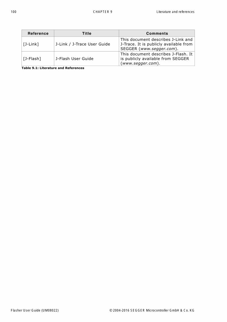
100 CHAPTER 9 Literature and references
Reference Title Comments
[J-Link] J-Link / J-Trace User GuideThis document describes J-Link and J-Trace. It is publicly available from SEGGER (www.segger.com).
[J-Flash] J-Flash User GuideThis document describes J-Flash. It is publicly available from SEGGER (www.segger.com).
Table 9.1: Literature and References
Flasher User Guide (UM08022) © 2004-2016 SEGGER Microcontroller GmbH & Co. KG
101
Index
AAdaptive clocking .................................96
CCache cleaning ....................................96Coprocessor ........................................96
DDirty data ...........................................96
HHalfword .............................................96Host ...................................................96
IICache ...............................................96ID .....................................................96IEEE 1149.1 ........................................96Image ................................................96Instruction Register ..............................96IR ......................................................96
JJ-Link
Adapters ..........................................85Features ...........................................12Specifications ....................................14Supported chips .......................... 59, 84
Joint Test Action Group (JTAG) ...............96
LLittle-endian .......................................96
MMemory coherency ...............................96Memory management unit (MMU) ..........97Memory Protection Unit (MPU) ...............97
NnTRST .......................................... 78, 97
OOpen collector .................................... 97
PProcessor Core ................................... 97
RRemapping ......................................... 97RESET ............................................... 97RTOS ................................................. 97
SSupport ........................................ 89, 95
TTAP Controller .................................... 97Target ............................................... 97TCK .............................................. 78, 97TDI .............................................. 78, 97TDO ............................................. 78, 97Test Access Port (TAP) ......................... 97Transistor-transistor logic (TTL) ............. 98
WWord ................................................. 98
Flasher User Guide (UM08022) © 2004-2016 SEGGER Microcontroller GmbH & Co. KG
102 Index
Flasher User Guide (UM08022) © 2004-2016 SEGGER Microcontroller GmbH & Co. KG