Embed Size (px)
Citation preview
ASCTB14E 202105Panasonic Corporation 2021
Contact arrangement 2:2 Form C (2 Form D)
Contact materialNil : Standard contact22 : MBB conatct (PC board terminal , (Standard/Self-clinching terminal) only)
Terminal shape / Operating function 0 : Standard PC board terminal type or Surface-mount terminal Single side stable 1 : Standard PC board terminal type or Surface-mount terminal 1 coil latching 2 : Standard PC board terminal type or Surface-mount terminal 2 coil latching (L2) 3 : PC board terminal (Self-clinching) terminal Single side stable 4 : PC board terminal (Self-clinching) terminal 1 coil latching 5 : PC board terminal (Self-clinching) terminal 2 coil latching
Packing style*3
Nil : Tube packingX : Tape and reel(picked from 1/2/3/4/5-pin side)Z : Tape and reel packing(picked from the 6/7/8/9/10-pin side)W : Tape and reel packing (picked from the 1/2/3/4/5-pin side) With humidity indicator and silica gel in moisture proof bag*4
Y : ape and reel packing (picked from the 6/7/8/9/10-pin side) With humidity indicator and silica gel in moisture proof bag*4
*1: 48 V coil type: Single side stable only*2: In case of 5 V transistor drive circuit, it is recommended to use 4.5 V type relay.*3: The “W” and “Y” at the end of the part number is only available for SA and SS.*4: Each reel is packed with humidity indicators and silica gel in the moisuture proof pack.
Rated coil voltage (DC)*1, *2
0:1.5 V, 1:3 V, 2:6 V, 3:12 V, 4:24 V,5:48 V, 6:4.5 V, 7:9 V, 9:5 V
Surface-mount typeNil : PC board terminal , (Standard/Self-clinching terminal)SA : SA typeSL : SL typeSS : SS type
2ATQ
FEATURES3 types of terminal shapes: PC board terminal (standard/self-clinching terminal) Surface-mount terminalConfort to FCC Part68: Surge withstand voltage 1,500 V (between open contacts)M.B.B. contact availableSurface-mount terminal conform to JIS C0806 standard
Flat, 5 mm 2 Form C, 2A, Surface mount terminal relaysTQ RELAYS
Signal Relays (2A or less)
TYPICAL APPLICATIONSTelecommunications and measurement equipmentTelephone related equipmentOA equipmentIndustrial machines
(Unit:mm)
Protective construction:Sealed type
99
55
1414
99
5.6
1414
ORDERING INFORMATION (PART NO. : Ordering part number for Japanese market)
industrial.panasonic.com/ac/e/2021.05 ー 1 ー
Signal Relays (2A or less) TQ RELAYS
Panasonic Corporation Electromechanical Control Business Divisionindustrial.panasonic.com/ac/e/ ASCTB14E 202105Panasonic Corporation 2021
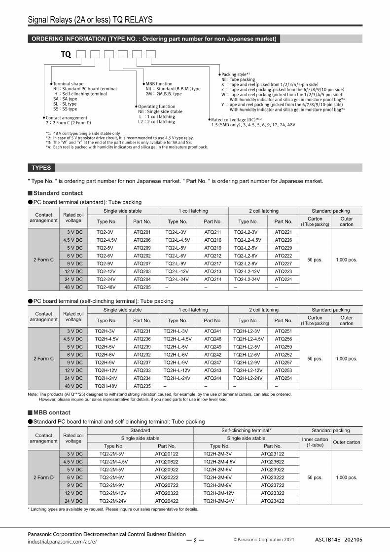
Rated coil voltage(DC)*1,2
1.5(SMD only), 3, 4.5, 5, 6, 9, 12, 24, 48V
Terminal shapeNil :Standard PC board terminal H :Self-clinching terminal
SA :SA typeSL :SL typeSS :SS type
Packing style*3
Nil : Tube packingX : Tape and reel(picked from 1/2/3/4/5-pin side)Z : Tape and reel packing(picked from the 6/7/8/9/10-pin side)W : Tape and reel packing (picked from the 1/2/3/4/5-pin side) With humidity indicator and silica gel in moisture proof bag*4
Y : ape and reel packing (picked from the 6/7/8/9/10-pin side) With humidity indicator and silica gel in moisture proof bag*4
Operating functionNil : Single side stableL : 1 coil latching
L2 : 2 coil latchingContact arrangement 2:2 Form C (2 Form D)
MBB functionNil : Standard(B.B.M.)type 2M : 2M.B.B. type
*1: 48 V coil type: Single side stable only*2: In case of 5 V transistor drive circuit, it is recommended to use 4.5 V type relay.*3: The “W” and “Y” at the end of the part number is only available for SA and SS.*4: Each reel is packed with humidity indicators and silica gel in the moisuture proof pack.
TQ
TYPES
Standard contactPC board terminal (standard): Tube packing
Contact arrangement
Rated coil voltage
Single side stable 1 coil latching 2 coil latching Standard packing
Type No. Part No. Type No. Part No. Type No. Part No. Carton(1 Tube packing)
Outer carton
2 Form C
3 V DC TQ2-3V ATQ201 TQ2-L-3V ATQ211 TQ2-L2-3V ATQ221
50 pcs. 1,000 pcs.
4.5 V DC TQ2-4.5V ATQ206 TQ2-L-4.5V ATQ216 TQ2-L2-4.5V ATQ2265 V DC TQ2-5V ATQ209 TQ2-L-5V ATQ219 TQ2-L2-5V ATQ2296 V DC TQ2-6V ATQ202 TQ2-L-6V ATQ212 TQ2-L2-6V ATQ2229 V DC TQ2-9V ATQ207 TQ2-L-9V ATQ217 TQ2-L2-9V ATQ227
12 V DC TQ2-12V ATQ203 TQ2-L-12V ATQ213 TQ2-L2-12V ATQ22324 V DC TQ2-24V ATQ204 TQ2-L-24V ATQ214 TQ2-L2-24V ATQ22448 V DC TQ2-48V ATQ205 – – – –
PC board terminal (self-clinching terminal): Tube packing
Contact arrangement
Rated coil voltage
Single side stable 1 coil latching 2 coil latching Standard packing
Type No. Part No. Type No. Part No. Type No. Part No. Carton(1 Tube packing)
Outer carton
2 Form C
3 V DC TQ2H-3V ATQ231 TQ2H-L-3V ATQ241 TQ2H-L2-3V ATQ251
50 pcs. 1,000 pcs.
4.5 V DC TQ2H-4.5V ATQ236 TQ2H-L-4.5V ATQ246 TQ2H-L2-4.5V ATQ2565 V DC TQ2H-5V ATQ239 TQ2H-L-5V ATQ249 TQ2H-L2-5V ATQ2596 V DC TQ2H-6V ATQ232 TQ2H-L-6V ATQ242 TQ2H-L2-6V ATQ2529 V DC TQ2H-9V ATQ237 TQ2H-L-9V ATQ247 TQ2H-L2-9V ATQ257
12 V DC TQ2H-12V ATQ233 TQ2H-L-12V ATQ243 TQ2H-L2-12V ATQ25324 V DC TQ2H-24V ATQ234 TQ2H-L-24V ATQ244 TQ2H-L2-24V ATQ25448 V DC TQ2H-48V ATQ235 – – – –
Note: The products (ATQ***25) designed to withstand strong vibration caused, for example, by the use of terminal cutters, can also be ordered. However, please inquire our sales representative for details, if you need parts for use in low level load.
MBB contactStandard PC board terminal and self-clinching terminal: Tube packing
Contact arrangement
Rated coil voltage
Standard Self-clinching terminal* Standard packingSingle side stable Single side stable Inner carton
(1-tube) Outer cartonType No. Part No. Type No. Part No.
2 Form D
3 V DC TQ2-2M-3V ATQ20122 TQ2H-2M-3V ATQ23122
50 pcs. 1,000 pcs.
4.5 V DC TQ2-2M-4.5V ATQ20622 TQ2H-2M-4.5V ATQ236225 V DC TQ2-2M-5V ATQ20922 TQ2H-2M-5V ATQ239226 V DC TQ2-2M-6V ATQ20222 TQ2H-2M-6V ATQ232229 V DC TQ2-2M-9V ATQ20722 TQ2H-2M-9V ATQ23722
12 V DC TQ2-2M-12V ATQ20322 TQ2H-2M-12V ATQ2332224 V DC TQ2-2M-24V ATQ20422 TQ2H-2M-24V ATQ23422
* Latching types are available by request. Please inquire our sales representative for details.
ORDERING INFORMATION (TYPE NO. : Ordering part number for non Japanese market)
" Type No. " is ordering part number for non Japanese market. " Part No. " is ordering part number for Japanese market.
ー 2 ー
Signal Relays (2A or less) TQ RELAYS
Panasonic Corporation Electromechanical Control Business Divisionindustrial.panasonic.com/ac/e/ ASCTB14E 202105Panasonic Corporation 2021
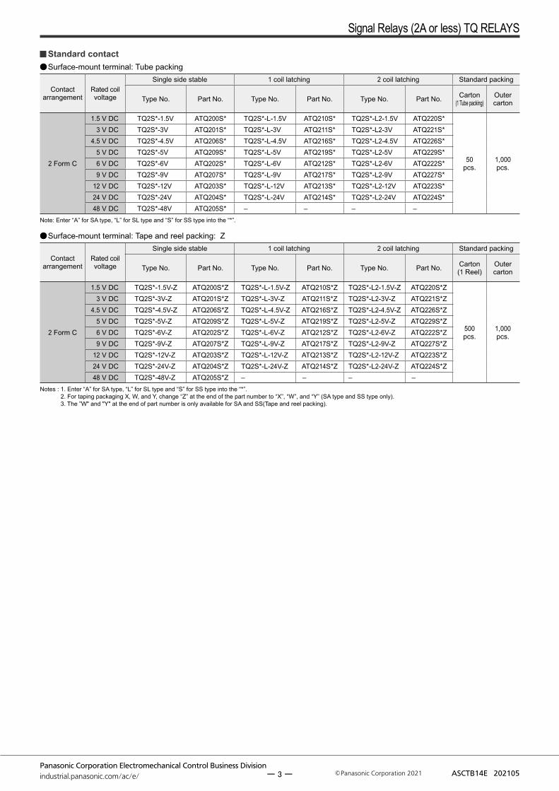
Standard contactSurface-mount terminal: Tube packing
Contact arrangement
Rated coil voltage
Single side stable 1 coil latching 2 coil latching Standard packing
Type No. Part No. Type No. Part No. Type No. Part No. Carton (1 Tube packing)
Outer carton
2 Form C
1.5 V DC TQ2S*-1.5V ATQ200S* TQ2S*-L-1.5V ATQ210S* TQ2S*-L2-1.5V ATQ220S*
50pcs.
1,000 pcs.
3 V DC TQ2S*-3V ATQ201S* TQ2S*-L-3V ATQ211S* TQ2S*-L2-3V ATQ221S*4.5 V DC TQ2S*-4.5V ATQ206S* TQ2S*-L-4.5V ATQ216S* TQ2S*-L2-4.5V ATQ226S*
5 V DC TQ2S*-5V ATQ209S* TQ2S*-L-5V ATQ219S* TQ2S*-L2-5V ATQ229S*6 V DC TQ2S*-6V ATQ202S* TQ2S*-L-6V ATQ212S* TQ2S*-L2-6V ATQ222S*9 V DC TQ2S*-9V ATQ207S* TQ2S*-L-9V ATQ217S* TQ2S*-L2-9V ATQ227S*
12 V DC TQ2S*-12V ATQ203S* TQ2S*-L-12V ATQ213S* TQ2S*-L2-12V ATQ223S*24 V DC TQ2S*-24V ATQ204S* TQ2S*-L-24V ATQ214S* TQ2S*-L2-24V ATQ224S*48 V DC TQ2S*-48V ATQ205S* – – – –
Note: Enter “A” for SA type, “L” for SL type and “S” for SS type into the “*”.
Surface-mount terminal: Tape and reel packing: Z
Contact arrangement
Rated coil voltage
Single side stable 1 coil latching 2 coil latching Standard packing
Type No. Part No. Type No. Part No. Type No. Part No. Carton (1 Reel)
Outer carton
2 Form C
1.5 V DC TQ2S*-1.5V-Z ATQ200S*Z TQ2S*-L-1.5V-Z ATQ210S*Z TQ2S*-L2-1.5V-Z ATQ220S*Z
500pcs.
1,000 pcs.
3 V DC TQ2S*-3V-Z ATQ201S*Z TQ2S*-L-3V-Z ATQ211S*Z TQ2S*-L2-3V-Z ATQ221S*Z4.5 V DC TQ2S*-4.5V-Z ATQ206S*Z TQ2S*-L-4.5V-Z ATQ216S*Z TQ2S*-L2-4.5V-Z ATQ226S*Z
5 V DC TQ2S*-5V-Z ATQ209S*Z TQ2S*-L-5V-Z ATQ219S*Z TQ2S*-L2-5V-Z ATQ229S*Z6 V DC TQ2S*-6V-Z ATQ202S*Z TQ2S*-L-6V-Z ATQ212S*Z TQ2S*-L2-6V-Z ATQ222S*Z9 V DC TQ2S*-9V-Z ATQ207S*Z TQ2S*-L-9V-Z ATQ217S*Z TQ2S*-L2-9V-Z ATQ227S*Z
12 V DC TQ2S*-12V-Z ATQ203S*Z TQ2S*-L-12V-Z ATQ213S*Z TQ2S*-L2-12V-Z ATQ223S*Z24 V DC TQ2S*-24V-Z ATQ204S*Z TQ2S*-L-24V-Z ATQ214S*Z TQ2S*-L2-24V-Z ATQ224S*Z48 V DC TQ2S*-48V-Z ATQ205S*Z – – – –
Notes : 1. Enter “A” for SA type, “L” for SL type and “S” for SS type into the “*”. 2. For taping packaging X, W, and Y, change “Z” at the end of the part number to “X”, “W”, and “Y” (SA type and SS type only). 3. The ”W" and "Y" at the end of part number is only available for SA and SS(Tape and reel packing).
ー 3 ー
Signal Relays (2A or less) TQ RELAYS
Panasonic Corporation Electromechanical Control Business Divisionindustrial.panasonic.com/ac/e/ ASCTB14E 202105Panasonic Corporation 2021
Coil data
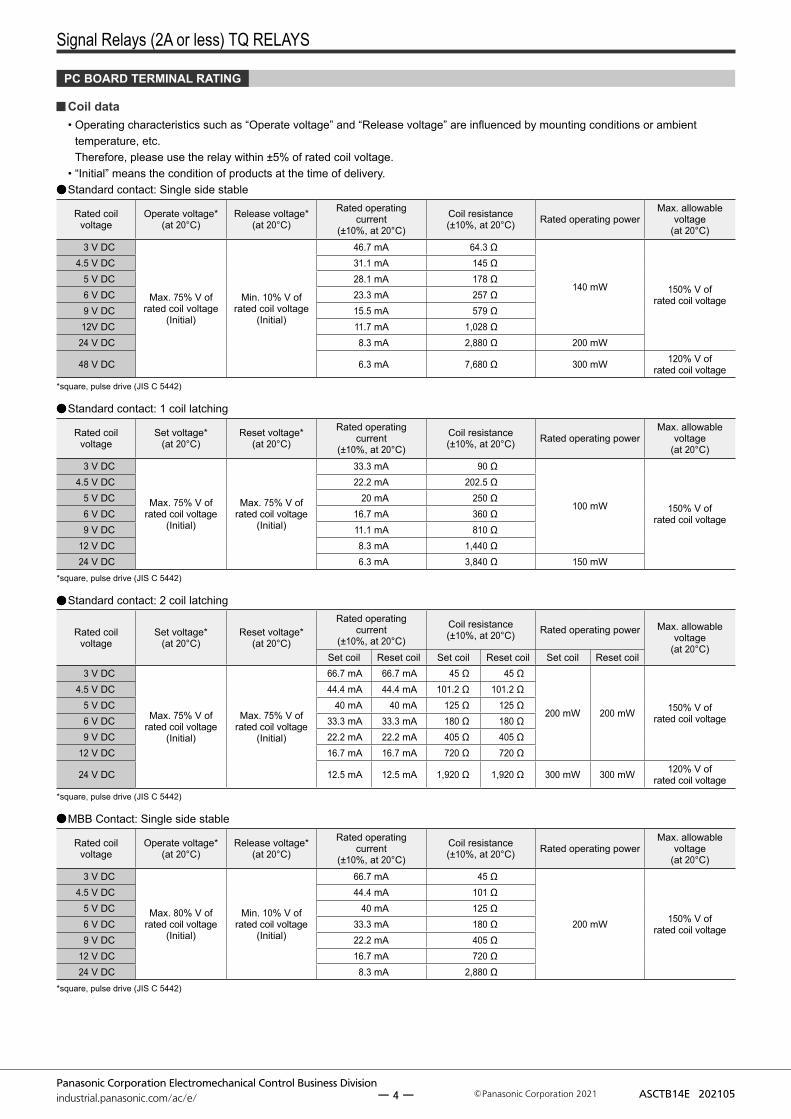
PC BOARD TERMINAL RATING
• Operating characteristics such as “Operate voltage” and “Release voltage” are influenced by mounting conditions or ambient temperature, etc. Therefore, please use the relay within ±5% of rated coil voltage.
• “Initial” means the condition of products at the time of delivery.Standard contact: Single side stable
Rated coil voltage
Operate voltage* (at 20°C)
Release voltage* (at 20°C)
Rated operating current
(±10%, at 20°C)
Coil resistance (±10%, at 20°C) Rated operating power
Max. allowable voltage
(at 20°C)3 V DC
Max. 75% V of rated coil voltage
(Initial)
Min. 10% V of rated coil voltage
(Initial)
46.7 mA 64.3 Ω
140 mW 150% V of rated coil voltage
4.5 V DC 31.1 mA 145 Ω5 V DC 28.1 mA 178 Ω6 V DC 23.3 mA 257 Ω9 V DC 15.5 mA 579 Ω12V DC 11.7 mA 1,028 Ω
24 V DC 8.3 mA 2,880 Ω 200 mW
48 V DC 6.3 mA 7,680 Ω 300 mW 120% V of rated coil voltage
*square, pulse drive (JIS C 5442)
Standard contact: 1 coil latching
Rated coil voltage
Set voltage* (at 20°C)
Reset voltage* (at 20°C)
Rated operating current
(±10%, at 20°C)
Coil resistance (±10%, at 20°C) Rated operating power
Max. allowable voltage
(at 20°C)3 V DC
Max. 75% V of rated coil voltage
(Initial)
Max. 75% V of rated coil voltage
(Initial)
33.3 mA 90 Ω
100 mW 150% V of rated coil voltage
4.5 V DC 22.2 mA 202.5 Ω5 V DC 20 mA 250 Ω6 V DC 16.7 mA 360 Ω9 V DC 11.1 mA 810 Ω
12 V DC 8.3 mA 1,440 Ω24 V DC 6.3 mA 3,840 Ω 150 mW
*square, pulse drive (JIS C 5442)
Standard contact: 2 coil latching
Rated coil voltage
Set voltage* (at 20°C)
Reset voltage* (at 20°C)
Rated operating current
(±10%, at 20°C)
Coil resistance (±10%, at 20°C) Rated operating power Max. allowable
voltage(at 20°C)
Set coil Reset coil Set coil Reset coil Set coil Reset coil3 V DC
Max. 75% V of rated coil voltage
(Initial)
Max. 75% V of rated coil voltage
(Initial)
66.7 mA 66.7 mA 45 Ω 45 Ω
200 mW 200 mW 150% V of rated coil voltage
4.5 V DC 44.4 mA 44.4 mA 101.2 Ω 101.2 Ω5 V DC 40 mA 40 mA 125 Ω 125 Ω6 V DC 33.3 mA 33.3 mA 180 Ω 180 Ω9 V DC 22.2 mA 22.2 mA 405 Ω 405 Ω
12 V DC 16.7 mA 16.7 mA 720 Ω 720 Ω
24 V DC 12.5 mA 12.5 mA 1,920 Ω 1,920 Ω 300 mW 300 mW 120% V of rated coil voltage
*square, pulse drive (JIS C 5442)
MBB Contact: Single side stable
Rated coil voltage
Operate voltage* (at 20°C)
Release voltage* (at 20°C)
Rated operating current
(±10%, at 20°C)
Coil resistance (±10%, at 20°C) Rated operating power
Max. allowable voltage
(at 20°C)3 V DC
Max. 80% V of rated coil voltage
(Initial)
Min. 10% V of rated coil voltage
(Initial)
66.7 mA 45 Ω
200 mW 150% V of rated coil voltage
4.5 V DC 44.4 mA 101 Ω5 V DC 40 mA 125 Ω6 V DC 33.3 mA 180 Ω9 V DC 22.2 mA 405 Ω
12 V DC 16.7 mA 720 Ω24 V DC 8.3 mA 2,880 Ω
*square, pulse drive (JIS C 5442)
ー 4 ー
Signal Relays (2A or less) TQ RELAYS
Panasonic Corporation Electromechanical Control Business Divisionindustrial.panasonic.com/ac/e/ ASCTB14E 202105Panasonic Corporation 2021
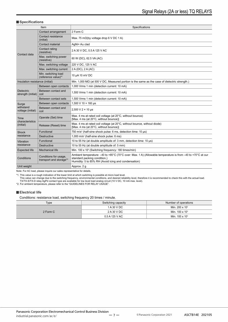
SpecificationsItem Specifications
Contact data
Contact arrangement 2 Form C 2 Form D (M.B.B. contact)Contact resistance(initial) Max. 50 mΩ (by voltage drop 6 V DC 1 A)
Contact material Ag + Au cladContact rating(resistive) 1 A 30 V DC, 0.5 A 125 V AC
Max. switching power (resistive) 30 W (DC), 62.5 VA (AC)
Max. switching voltage 110 V DC, 125 V ACMax. switching current 1 A (DC), 1 A (AC)Min. switching load(reference value)*1 10 μA 10 mV DC
Insulation resistance (initial) Min. 1,000 MΩ (at 500 V DC, Measured portion is the same as the case of dielectric strength.)
Dielectric strength (initial)
Between open contacts 750 Vrms for 1 min (detection current: 10 mA) 300 Vrms for 1 min (detection current: 10 mA)Between contact and coil 1,000 Vrms for 1 min (detection current: 10 mA)
Between contact sets 1,000 Vrms for 1 min (detection current: 10 mA)Surge withstand voltage (initial)
Between open contacts 1,500 V 10 × 160 μs
Time characteristics (initial)
Operate (Set) time Max. 3 ms at rated coil voltage (at 20°C, without bounce)[Max. 3 ms (at 20°C, without bounce)]
Release (Reset) time Max. 3 ms at rated coil voltage (at 20°C, without bounce, without diode)[Max. 3 ms (at 20°C, without bounce)]
Shock resistance
Functional 490 m/s2 (half-sine shock pulse: 11 ms, detection time: 10 μs)Destructive 980 m/s2 (half-sine shock pulse: 6 ms)
Vibration resistance
Functional 10 to 55 Hz (at double amplitude of: 3 mm, detection time: 10 μs)Destructive 10 to 55 Hz (at double amplitude of: 5 mm)
Expected life Mechanical life Min. 100 x 106 (switching frequency: 180 times/min) Min. 10 x 106 (switching frequency: 180 times/min)
Conditions Conditions for usage, transport and storage*2
Ambient temperature: –40 to +70°C(Allowable temperature is from –40 to +60°C at our standard packing condition.) Humidity: 5 to 85% RH(Avoid icing and condensation)
Ambient temperature: –40 to +50°C(Allowable temperature is from –40 to +50°C at our standard packing condition.) Humidity: 5 to 85% RH(Avoid icing and condensation)
Unit weight Approx. 1.5 gNote: For AC load, please inquire our sales representative for details.*1. This value is a rough indication of the lower limit at which switching is possible at micro load level.
This value can change due to the switching frequency, environmental conditions, and desired reliability level, therefore it is recommended to check this with the actual load. TX/TX-S/TX-D relay AgPd contact type are available for low level load analog circuit (10 V DC, 10 mA max. level).
*2. For ambient temperature, please refer to the “GUIDELINES FOR RELAY USAGE”.
Electrical lifeConditions: resistance load, switching frequency 20 times / minute.
Type Switching capacity Number of operations
2 Form C Standard contact1 A 30 V DC Min. 200 x 103
0.5 A 125 V DC Min. 100 x 103
2 Form D M.B.B. contact 1 A 30 V DC Min. 100 x 103
ー 5 ー
Signal Relays (2A or less) TQ RELAYS
Panasonic Corporation Electromechanical Control Business Divisionindustrial.panasonic.com/ac/e/ ASCTB14E 202105Panasonic Corporation 2021
Coil data
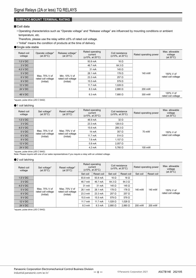
SURFACE-MOUNT TERMINAL RATING
• Operating characteristics such as “Operate voltage” and “Release voltage” are influenced by mounting conditions or ambient temperature, etc. Therefore, please use the relay within ±5% of rated coil voltage.
• “Initial” means the condition of products at the time of delivery.Single side stable
Rated coil voltage
Operate voltage* (at 20°C)
Release voltage* (at 20°C)
Rated operating current
(±10%, at 20°C)
Coil resistance (±10%, at 20°C) Rated operating power
Max. allowable voltage
(at 20°C)1.5 V DC
Max. 75% V of rated coil voltage
(Initial)
Min. 10% V of rated coil voltage
(Initial)
93.8 mA 16 Ω
140 mW 150% V of rated coil voltage
3 V DC 46.7 mA 64.3 Ω4.5 V DC 31 mA 145 Ω
5 V DC 28.1 mA 178 Ω6 V DC 23.3 mA 257 Ω9 V DC 15.5 mA 579 Ω
12 V DC 11.7 mA 1,028 Ω24 V DC 8.3 mA 2,880 Ω 200 mW
48 V DC 6.3 mA 7,680 Ω 300 mW 120% V of rated coil voltage
*square, pulse drive (JIS C 5442)
1 coil latching
Rated coil voltage
Set voltage* (at 20°C)
Reset voltage* (at 20°C)
Rated operating current
(±10%, at 20°C)
Coil resistance (±10%, at 20°C) Rated operating power
Max. allowable voltage
(at 20°C)1.5 V DC
Max. 75% V of rated coil voltage
(Initial)
Max. 75% V of rated coil voltage
(Initial)
46.9 mA 32 Ω
70 mW 150% V of rated coil voltage
3 V DC 23.3 mA 128.6 Ω4.5 V DC 15.6 mA 289.3 Ω
5 V DC 14 mA 357 Ω6 V DC 11.7 mA 514 Ω9 V DC 7.8 mA 1,157 Ω
12 V DC 5.8 mA 2,057 Ω24 V DC 4.2 mA 5,760 Ω 100 mW
*square, pulse drive (JIS C 5442)Note: Please inquire with one of our sales representatives if you require a relay with an unlisted voltage.
2 coil latching
Rated coil voltage
Set voltage* (at 20°C)
Reset voltage* (at 20°C)
Rated operating current
(±10%, at 20°C)
Coil resistance (±10%, at 20°C) Rated operating power Max. allowable
voltage(at 20°C)
Set coil Reset coil Set coil Reset coil Set coil Reset coil1.5 V DC
Max. 75% V of rated coil voltage
(Initial)
Max. 75% V of rated coil voltage
(Initial)
93.8 mA 93.8 mA 16 Ω 16 Ω
140 mW 140 mW 150% V of rated coil voltage
3 V DC 46.7 mA 46.7 mA 64.3 Ω 64.3 Ω4.5 V DC 31 mA 31 mA 145 Ω 145 Ω
5 V DC 28.1 mA 28.1 mA 178 Ω 178 Ω6 V DC 23.3 mA 23.3 mA 257 Ω 257 Ω9 V DC 15.5 mA 15.5 mA 579 Ω 579 Ω
12 V DC 11.7 mA 11.7 mA 1,028 Ω 1,028 Ω24 V DC 8.3 mA 8.3 mA 2,880 Ω 2,880 Ω 200 mW 200 mW
*square, pulse drive (JIS C 5442)
ー 6 ー
Signal Relays (2A or less) TQ RELAYS
Panasonic Corporation Electromechanical Control Business Divisionindustrial.panasonic.com/ac/e/ ASCTB14E 202105Panasonic Corporation 2021
SpecificationsItem Specifications
Contact data
Contact arrangement 2 Form CContact resistance(initial) Max. 75 mΩ(by voltage drop 6 V DC 1 A)
Contact material AgNi+ Au cladContact rating(resistive) 2 A 30 V DC, 0.5 A 125 V AC
Max. switching power (resistive) 60 W (DC), 62.5 VA (AC)
Max. switching voltage 220 V DC, 125 V ACMax. switching current 2 A (DC), 2 A (AC)Min. switching load(reference value)*1 10 μA 10 mV DC
Insulation resistance (initial) Min. 1,000 MΩ (at 500 V DC, Measured portion is the same as the case of dielectric strength.)
Dielectric strength (initial)
Between open contacts 1,000 Vrms 1 min (detection current: 10 mA)Between contact and coil 1,500 Vrms 1 min (detection current: 10 mA)
Between contact sets 1,500 Vrms 1 min (detection current: 10 mA)
Surge withstand voltage (initial)
Between open contacts 1,500 V 10 × 160 μsBetween contact andcoil 2,500 V 2 × 10 μs
Time characteristics (initial)
Operate (Set) time Max. 4 ms at rated coil voltage (at 20°C, without bounce)[Max. 4 ms (at 20°C, without bounce)]
Release (Reset) time Max. 4 ms at rated coil voltage (at 20°C, without bounce, without diode)[Max. 4 ms (at 20°C, without bounce)]
Shock resistance
Functional 750 m/s2 (half-sine shock pulse: 6 ms, detection time: 10 μs)Destructive 1,000 m/s2 (half-sine shock pulse: 6 ms)
Vibration resistance
Functional 10 to 55 Hz (at double amplitude of: 3 mm, detection time: 10 μs)Destructive 10 to 55 Hz (at double amplitude of: 5 mm)
Expected life Mechanical life Min. 100 x 106 (Switching frequency: 180 times/min)
Conditions Conditions for usage, transport and storage*2
Ambient temperature: –40 to +85°C (70°C over: Max. 1 A) (Allowable temperature is from –40 to +70°C at our standard packing condition.)Humidity: 5 to 85% RH (Avoid icing and condensation)
Unit weight Approx. 2 gNote: For AC load, please inquire our sales representative for details.*1. This value is a rough indication of the lower limit at which switching is possible at micro load level.
This value can change due to the switching frequency, environmental conditions, and desired reliability level, therefore it is recommended to check this with the actual load. TX/TX-S/TX-D relay AgPd contact type are available for low level load analog circuit (10 V DC, 10 mA max. level).
*2. For ambient temperature, please refer to the “GUIDELINES FOR RELAY USAGE”.
Electrical lifeConditions: resistance load, switching frequency 20 times / minute.
Type Switching capacity Number of operations
2 Form C1 A 30 V DC Min. 200 x 103
2 A 30 V DC Min. 100 x 103
0.5 A 125 V AC Min. 100 x 103
ー 7 ー
Signal Relays (2A or less) TQ RELAYS
Panasonic Corporation Electromechanical Control Business Divisionindustrial.panasonic.com/ac/e/ ASCTB14E 202105Panasonic Corporation 2021
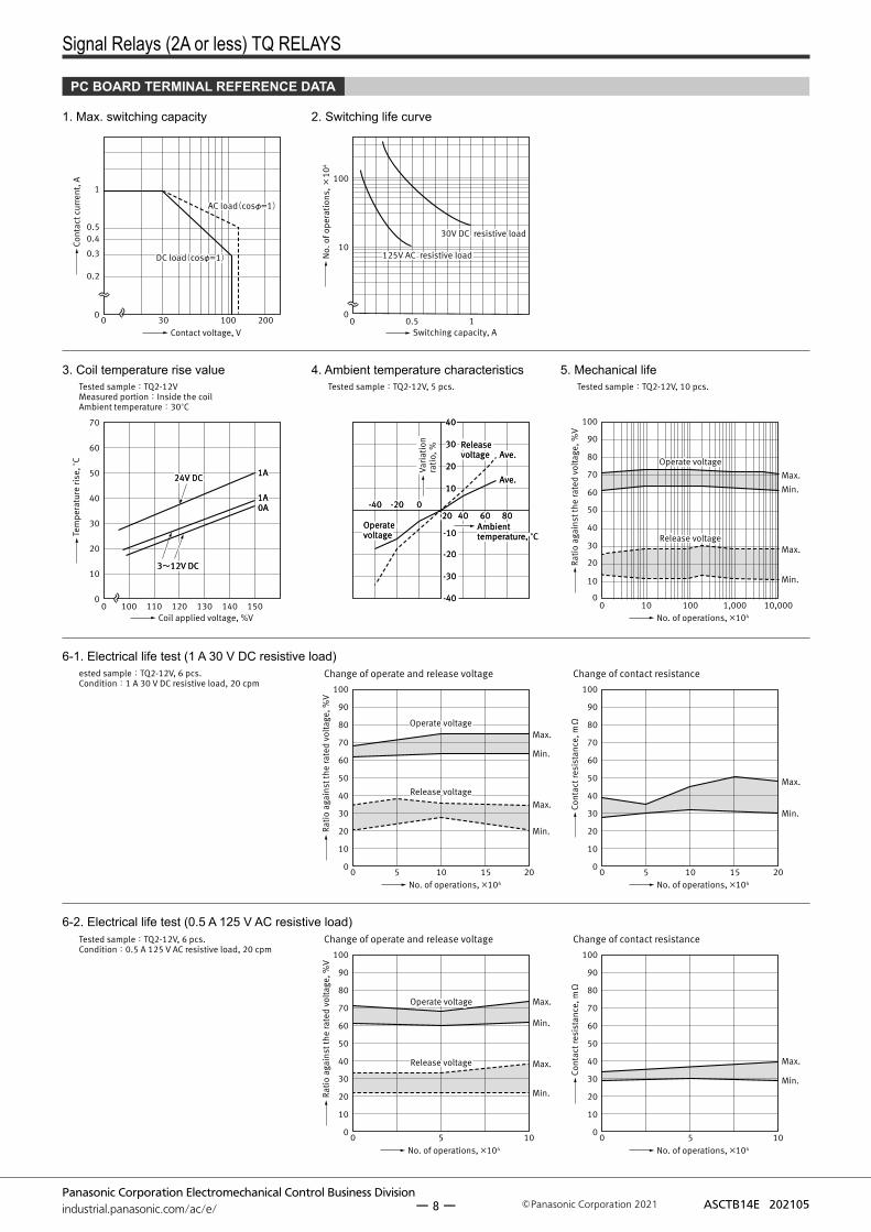
PC BOARD TERMINAL REFERENCE DATA
1. Max. switching capacity
300 100 200
1
0.50.4
0.3
0.2
0
Contact voltage, V
AC load(cosφ=1)AC load(cosφ=1)
DC load(cosφ=1)DC load(cosφ=1)
Cont
act c
urre
nt, A
2. Switching life curve
0 0.5 1
100
10
0
Switching capacity, A
125V AC resistive load 125V AC resistive load
30V DC resistive load30V DC resistive load
No.
of o
pera
tions
, ×10
4
3. Coil temperature rise value
Coil applied voltage, %V120110 1301000 140 150
70
60
50
40
30
20
10
0
1A1A
1A1A0A0A
Tested sample:TQ2-12VMeasured portion:Inside the coil Ambient temperature:30°C
24V DC24V DC
3~12V DC3~12V DC
Tem
pera
ture
rise
, °C
4. Ambient temperature characteristics
8080
Release voltageRelease voltage
Operate voltageOperate voltage
2020-40-40 -20-20 00
4040 6060
2020
1010
3030
4040
-10-10
-30-30
-40-40
-20-20
Ambienttemperature, °C Ambienttemperature, °C
Varia
tion
ratio
, %
Tested sample:TQ2-12V, 5 pcs.
Ave.Ave.
Ave.Ave.
5. Mechanical life
100
90
80
70
60
50
40
30
20
10
0100 100 1,000 10,000
Release voltageRelease voltage
Operate voltageOperate voltageMax.
Min.
Max.
Min.
No. of operations, ×104
Ratio
aga
inst
the
rate
d vo
ltage
, %V
Tested sample:TQ2-12V, 10 pcs.
6-1. Electrical life test (1 A 30 V DC resistive load)
0 2010 155 2010 1550
10
30
40
60
80
20
50
70
90
100
00
10
30
40
60
80
20
50
70
90
100
ested sample:TQ2-12V, 6 pcs.Condition:1 A 30 V DC resistive load, 20 cpm
Release voltageRelease voltage
Operate voltageOperate voltageMax.
Min.
Max.
Min.Max.
Min.
No. of operations, ×104 No. of operations, ×104
Change of operate and release voltage Change of contact resistance
Ratio
aga
inst
the
rate
d vo
ltage
, %V
Cont
act r
esis
tanc
e, mΩ
6-2. Electrical life test (0.5 A 125 V AC resistive load)
0 5 100
10
30
40
60
80
20
50
70
90
100
0 1050
10
30
40
60
80
20
50
70
90
100
Tested sample:TQ2-12V, 6 pcs.Condition:0.5 A 125 V AC resistive load, 20 cpm
Release voltageRelease voltage
Operate voltageOperate voltage Max.
Min.
Max.
Min.
Max.
Min.
Change of operate and release voltage Change of contact resistance
No. of operations, ×104 No. of operations, ×104
Ratio
aga
inst
the
rate
d vo
ltage
, %V
Cont
act r
esis
tanc
e, mΩ
ー 8 ー
Signal Relays (2A or less) TQ RELAYS
Panasonic Corporation Electromechanical Control Business Divisionindustrial.panasonic.com/ac/e/ ASCTB14E 202105Panasonic Corporation 2021
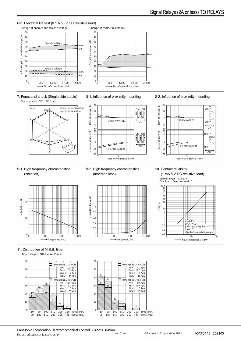
6-3. Electrical life test (0.1 A 53 V DC resistive load)
0 500 1,000 1,500 2,0000
10
20
30
40
50
60
70
80
90
100
Max.Min.
Release voltageRelease voltage
Operate voltageOperate voltage
Max.Min.
0 500 1,000 1,500 2,0000
10
20
30
40
50
60
70
80
90
100
Max.
Min.
Change of operate and release voltage Change of contact resistance
No. of operations, ×104 No. of operations, ×104
Ratio
aga
inst
the
rate
d vo
ltage
, %V
Cont
act r
esis
tanc
e, mΩ
7. Functional shock (Single side stable)
Y
Z
X’
Y’
Z’
X
Y’
YZ’
X
X’
Z
980[m/s2] Deenergized conditionEnergized condition
Tested sample:TQ2-12V, 6 pcs.
8-1. Influence of proximity mounting
0 5
-10
-20
0
10
20
-10
-20
0
1020
ON ON
ℓ ℓ
OFF
ON
OFF OFF
ℓ ℓ
Operate voltageOperate voltage
Release voltageRelease voltage
nter-relay distance ℓ , mm
Rate
of c
hang
e, %
Rate
of c
hang
e, %
8-2. Influence of proximity mounting
ON
ON
ONℓ
ℓ
OFF
OFF
OFFℓ
ℓ
0 5
-10
-20
0
10
20
-10
-20
0
1020
Operate voltageOperate voltage
Release voltageRelease voltage
nter-relay distance ℓ , mmRa
te o
f cha
nge,
%Ra
te o
f cha
nge,
%
9-1. High frequency characteristics (Isolation)
10 100 1,000
50
100
00
Frequency, MHz
Isol
atio
n, d
B
9-2. High frequency characteristics (Insertion loss)
0.2
0.4
0.6
0.8
1
10 100 1,00000
Frequency, MHz
Inse
rtio
n lo
ass,
dB
10. Contact reliability (1 mA 5 V DC resistive load)
0.1
0.2
0.5
1
2
5
10
305070
9599
99.9
1 10 100
Tested sample:TQ2-12V Condition:Detection level 10
No. of operations, ×106
m=2.15μ=2.7×10⁷
95% reliability limit = 7.6×10⁶
(Weibull probability paper)
F(t)
, %
11. Distribution of M.B.B. time
50~
100100~
150150~
200200~
250250~
300300μs min.~
350μs max.300μs min.~
350μs max.10~
50
4141
3535
1212
31312727
1010
44
77
11 22
15151919 2121
2626
1919
3030
1111
1717
44 2266
0
10
20
30
40
50
60
Tested sample:TQ2-2M-5V, 85 pcs.
50~
100100~
150150~
200200~
250250~
30010~
50
0
10
20
30
40
50
60Terminal No.2-3-4 ON
Terminal No.7-8-9 ON
Ave. : 105.6 μs3σn-1 : 163.8 μsMin. : 23 μsMax. : 243 μs
Ave. : 115.6 μs3σn-1 : 167.3 μsMin. : 35 μsMax. : 254 μs
Terminal No.2-3-4 ON
Terminal No.7-8-9 ON
Ave. : 71.6 μs3σn-1 : 127.1 μsMin. : 17 μsMax. : 187 μs
Ave. : 80.7 μs3σn-1 : 156.7 μsMin. : 29 μsMax. : 298 μs
ー 9 ー
Signal Relays (2A or less) TQ RELAYS
Panasonic Corporation Electromechanical Control Business Divisionindustrial.panasonic.com/ac/e/ ASCTB14E 202105Panasonic Corporation 2021
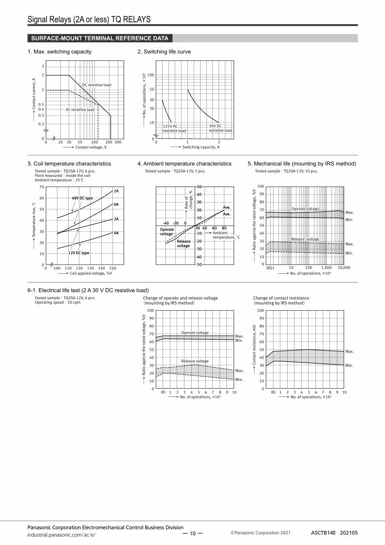
SURFACE-MOUNT TERMINAL REFERENCE DATA
1. Max. switching capacity
Contact voltage, V
0.2
020 30 50 100 200 3000
0.3
0.40.5
1
2
3
DC resistive loadDC resistive load
AC resistive loadAC resistive loadCont
act c
urre
nt, A
2. Switching life curve
100
50
30
20
10
10 20
125V AC resistive load125V AC resistive load
30V DC resistive load30V DC resistive load
Switching capacity, AN
o. o
f ope
ratio
ns, ×
104
3. Coil temperature characteristics
Coil applied voltage, %V120110 1301000 140 150
70
60
50
40
30
20
10
0
2A2A
0A0A
2A2A
0A0A
Tested sample:TQ2SA-12V, 6 pcs. Point measured:Inside the coil Ambient temperature:25°C
48V DC type48V DC type
12V DC type12V DC type
Tem
pera
ture
rise
, °C
4. Ambient temperature characteristics
Rate
of
chan
ge, %
8080Operate voltageOperate voltage
Release voltageRelease voltage
2020-40-40 -20-20 00
4040 6060
2020
1010
4040
5050
3030
-40-40
-20-20
-10-10
-30-30
-50-50
Tested sample:TQ2SA-12V, 5 pcs.
Ambienttemperature, °C
Ave.Ave.
Ave.Ave.
5. Mechanical life (mounting by IRS method)
100
90
80
70
60
50
40
30
20
10
010 100 1,000 10,000IRS1
Release voltageRelease voltage
Operate voltageOperate voltageMax.
Min.
Max.
Min.
No. of operations, ×104
Tested sample:TQ2SA-12V, 10 pcs.
Ratio
aga
inst
the
rate
d vo
ltage
, %V
6-1. Electrical life test (2 A 30 V DC resistive load)
10IRS 2 3 4 5 6 7 8 91 10IRS 2 3 4 5 6 7 8 910
10
30
40
60
80
20
50
70
90
100
0
10
30
40
60
80
20
50
70
90
100
Tested sample:TQ2SA-12V, 6 pcs.Operating speed:20 cpm
Release voltageRelease voltage
Operate voltageOperate voltageMax.Min.
Max.
Min.Max.
Min.
No. of operations, ×104 No. of operations, ×104
Change of operate and release voltage (mounting by IRS method)
Change of contact resistance(mounting by IRS method)
Ratio
aga
inst
the
rate
d vo
ltage
, %V
Cont
act r
esis
tanc
e, mΩ
ー 10 ー
Signal Relays (2A or less) TQ RELAYS
Panasonic Corporation Electromechanical Control Business Divisionindustrial.panasonic.com/ac/e/ ASCTB14E 202105Panasonic Corporation 2021
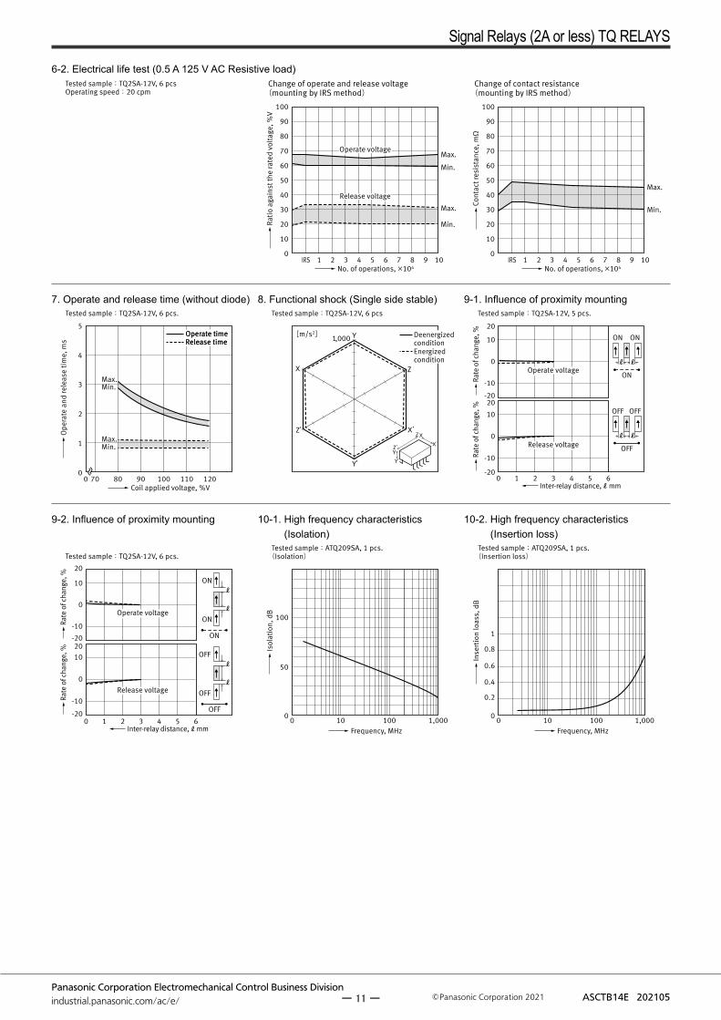
6-2. Electrical life test (0.5 A 125 V AC Resistive load)
10IRS 2 3 4 5 6 7 8 91 10IRS 2 3 4 5 6 7 8 910
10
30
40
60
80
20
50
70
90
100
0
10
30
40
60
80
20
50
70
90
100
Max.
Min.
Tested sample:TQ2SA-12V, 6 pcsOperating speed:20 cpm
Release voltageRelease voltage
Operate voltageOperate voltageMax.
Min.
Max.
Min.
No. of operations, ×104 No. of operations, ×104
Change of operate and release voltage (mounting by IRS method)
Change of contact resistance(mounting by IRS method)
Ratio
aga
inst
the
rate
d vo
ltage
, %V
Cont
act r
esis
tanc
e, mΩ
7. Operate and release time (without diode)
100 120700 80 90 1100
1
3
4
2
5
Max.Min.
Max.Min.
Coil applied voltage, %V
Operate timeRelease time Operate timeRelease time
Tested sample:TQ2SA-12V, 6 pcs.
Ope
rate
and
rele
ase
time,
ms
8. Functional shock (Single side stable)
Y
Z
X’
Y’
Z’
X
Y’
YZ’
X
X’
Z
1,000[m/s2] DeenergizedconditionEnergizedcondition
Tested sample:TQ2SA-12V, 6 pcs
9-1. Influence of proximity mounting
-10
0
10
20
-10
-20
20-20
0
10
ON ON
ℓ ℓ
OFF
ON
OFF OFF
ℓ ℓ
531 2 40 6
Operate voltageOperate voltage
Release voltageRelease voltage
Tested sample:TQ2SA-12V, 5 pcs.
Inter-relay distance, ℓ mm
Rate
of c
hang
e, %
Rate
of c
hang
e, %
9-2. Influence of proximity mounting
ON
ON
ONℓ
ℓ
OFF
OFF
OFFℓ
ℓ
531 2 40 6
-10
-20
0
10
20
-10
-20
0
1020
Operate voltageOperate voltage
Release voltageRelease voltage
Tested sample:TQ2SA-12V, 6 pcs.
Inter-relay distance, ℓ mm
Rate
of c
hang
e, %
Rate
of c
hang
e, %
10-1. High frequency characteristics (Isolation)
10 100 1,000
50
100
00
Frequency, MHz
Tested sample:ATQ209SA, 1 pcs.(Isolation)
Isol
atio
n, d
B
10-2. High frequency characteristics (Insertion loss)
0.2
0.4
0.6
0.8
1
10 100 1,00000
Frequency, MHz
Tested sample:ATQ209SA, 1 pcs.(Insertion loss)
Inse
rtio
n lo
ass,
dB
ー 11 ー
Signal Relays (2A or less) TQ RELAYS
Panasonic Corporation Electromechanical Control Business Divisionindustrial.panasonic.com/ac/e/ ASCTB14E 202105Panasonic Corporation 2021
0 .25
0 .25
0.5 0.257.62
9
2.54
3.5
5+0.4
ー0.2
(4.7
5)
14
General tolerance:±0.3
0 .25
0 .25
0.5 0.257.62
9
2.54
3.5
5+0.4
ー0.2
(4.7
5)
14
General tolerance:±0.3
2 .54
7 .62
2.5410.16
10-1.0 dia.
Tolerance:±0.1
Direction indication
-
+
1
10 78
4
9
2
6
53
Direction indication
-+
-+
1
10 78
4
9
2
6
53
Direction indication
+
-
1
10 78
4
9
2
6
53
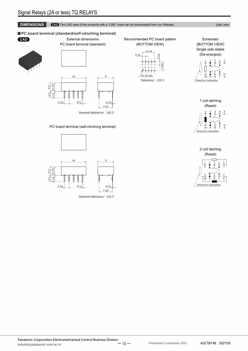
DIMENSIONS CAD The CAD data of the products with a “CAD” mark can be downloaded from our Website. Unit: mm
CAD External dimensionsPC board terminal (standard)
Recommended PC board pattern(BOTTOM VIEW)
PC board terminal (standard/self-clinching terminal)Schematic
(BOTTOM VIEW)Single side stable
(De-energize)
1 coil latching(Reset)
PC board terminal (self-clinching terminal)
2 coil latching(Reset)
ー 12 ー

Signal Relays (2A or less) TQ RELAYS
Panasonic Corporation Electromechanical Control Business Divisionindustrial.panasonic.com/ac/e/ ASCTB14E 202105Panasonic Corporation 2021
Direction indication
+
-
10
1 43
7
2
9
5
68
Direction indication
-
-
+
+
10
1 43
7
2
9
5
68
Direction indication
-
+
10
1 43
7
2
9
5
68
CADSurface-mount terminal
Type External dimensionsRecommended PC board
pattern(TOP VIEW)
SA
General tolerance :±0.3
0.52.540.
25 .
6
14
9
0.25
11.5±0.57.62
4.9
9 .56
2.541
2.94
Tolerance :±0.1
SL
General tolerance :±0.3
0.52.54
Max
.7.5
14
9
0.25
11.5±0.57.62
4.9
9 .56
2.541
2.94
Tolerance :±0.1
SS
General tolerance :±0.3
0.52.54
Max
.7.5
14
9
0.25
9.3±0.57.62
4.9
8 .46
2.541
1.84
Tolerance :±0.1
Schematic(TOP VIEW)
Single side stable(De-energize)
1 coil latching(Reset)
2 coil latching(Reset)
Tube packing
Stopper(gray)
Orientation(indicates PIN No.1)stripe
Stopper(green)
1. The relay is packing in a tube with the relay orientation mark on the left side,as shown in the figure below. Be sure to maintain relays in the correct orientation when mounting on PC boards.
2. Conditions for operation, transport and storage : –40 to 60°C.
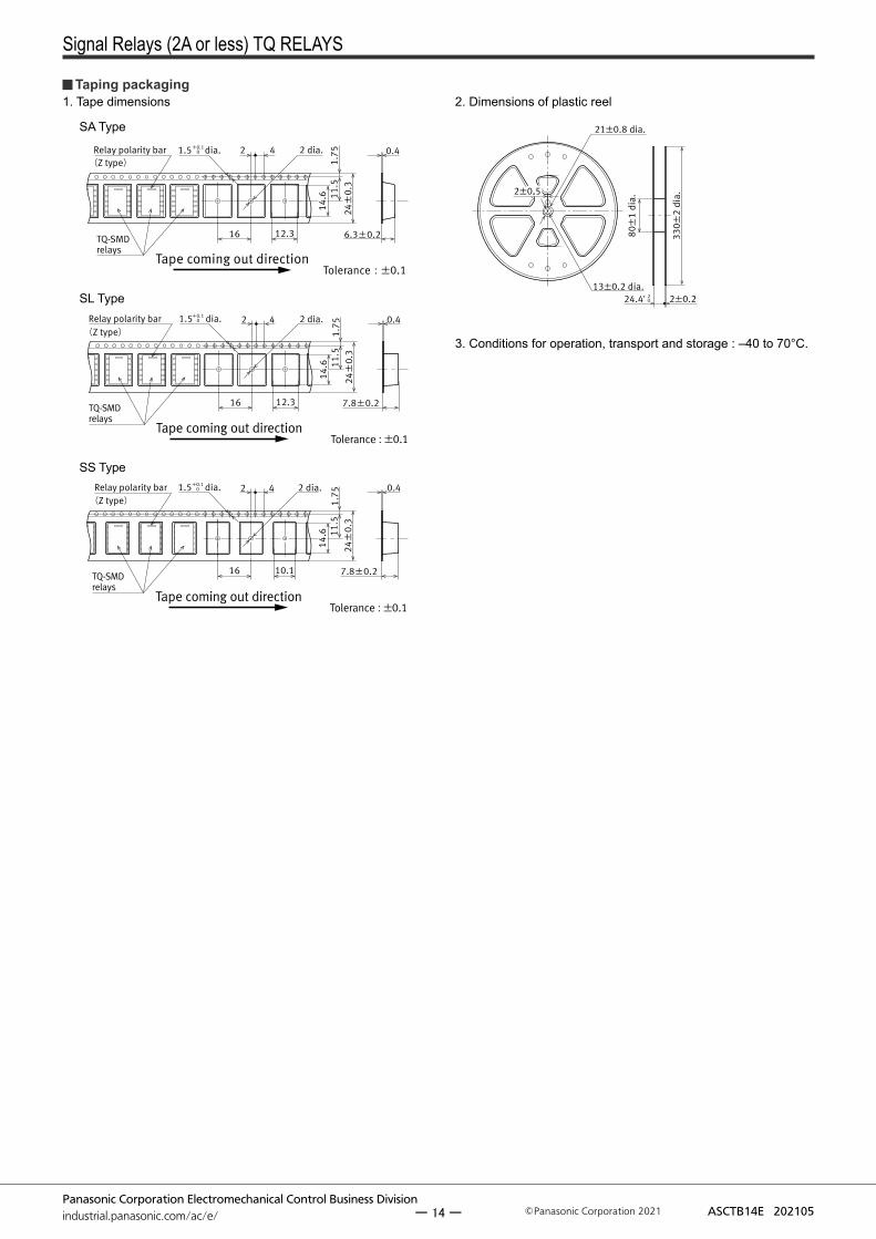
PACKING STYLE Unit: mm
ー 13 ー
Signal Relays (2A or less) TQ RELAYS
Panasonic Corporation Electromechanical Control Business Divisionindustrial.panasonic.com/ac/e/ ASCTB14E 202105Panasonic Corporation 2021
Relay polarity bar
TQ-SMD relays
1.5 2 dia.4 0.4
1.75
11.5
14.6
14.6
6.3±0.2
24±
0 .3
2
16 12.3
+0.1 0
Tolerance :±0.1Tape coming out direction
(Z type)dia.
Relay polarity bar
TQ-SMD relays
1.5 2 dia.4 0.41.
7511
.514
.614
.6
7.8±0.2
24±
0 .3
2
16 12.3
+0.1 0
Tolerance:±0.1Tape coming out direction
(Z type)dia.
Relay polarity bar
TQ-SMD relays
1.5 2 dia.4 0.4
1.75
11.5
14.6
14.6
7.8±0.2
24±
0 .3
2
16 10.1
+0.1 0
(Z type)
Tolerance:±0.1Tape coming out direction
dia.
330±
2 di
a.
80±
1 di
a.
24.4 2±0.2
2±0.52±0.5
13±0.2 dia.
21±0.8 dia.
+ 2 0
3. Conditions for operation, transport and storage : –40 to 70°C.
SA Type
SL Type
SS Type
1. Tape dimensions 2. Dimensions of plastic reel Taping packaging
ー 14 ー
Signal Relays (2A or less) TQ RELAYS
Panasonic Corporation Electromechanical Control Business Divisionindustrial.panasonic.com/ac/e/ ASCTB14E 202105Panasonic Corporation 2021
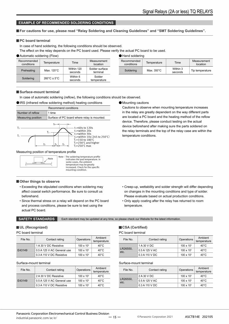
NoteNote:The soldering temperature profile
indicates the pad temperature. In some cases, the ambient temperature may be greatly increased. Check for the specific mounting condition.
T3
T2
T1
t 1=60s to 120s t 2=within 20s t 3=within 30s t 4=within 10s(245 to 250°C)T1=150 to 180°CT2=230°C and higherT3=250°C max t1 t3t2
t4
EXAMPLE OF RECOMMENDED SOLDERING CONDITIONS
For cautions for use, please read “Relay Soldering and Cleaning Guidelines” and “SMT Soldering Guidelines”.
PC board terminalIn case of hand soldering, the following conditions should be observed.The effect on the relay depends on the PC board used. Please verify the actual PC board to be used.Automatic soldering (Flow)
Recommended conditions Temperature Time Measurement
location
Preheating Max. 120°C Within 120 seconds
Solder surface terminal
Soldering 260°C ± 5°C Within 6 seconds
Solder temperature
Hand solderingRecommended
conditions Temperature Time Measurement location
Soldering Max. 350°C Within 3 seconds Tip temperature
Surface-mount terminalIn case of automatic soldering (reflow), the following conditions should be observed.IRS (infrared reflow soldering method) heating conditions
Recommend conditionsNumber of reflow 1 timeMeasuring position Surface of PC board where relay is mounted.
Mounting cautionsCautions to observe when mounting temperature increases in the relay are greatly dependent on the way different parts are located a PC board and the heating method of the reflow device. Therefore, please conduct testing on the actual device beforehand after making sure the parts soldered on the relay terminals and the top of the relay case are within the temperature conditions.
Measuring position of temperature profile
Other things to observe• Exceeding the stipulated conditions when soldering may
affect coaxial switch performance. Be sure to consult us beforehand.
• Since thermal stress on a relay will depend on the PC board and process conditions, please be sure to test using the actual PC board.
• Creep-up, wettability and solder strength will differ depending on changes in the mounting conditions and type of solder. Please evaluate based on actual production conditions.
• Only apply coating after the relay has returned to room temperature.
UL (Recognized)PC board terminal
File No. Contact rating Operations Ambienttemperature
E431491 A 30 V DC Resistive 100 x 103 40°C0.5 A 125 V AC General use 100 x 103 40°C0.3 A 110 V DC Resistive 100 x 103 40°C
Surface-mount terminal
File No. Contact rating Operations Ambienttemperature
E431492 A 30 V DC Resistive 100 x 103 40°C0.5 A 125 V AC General use 100 x 103 40°C0.3 A 110 V DC Resistive 100 x 103 40°C
CSA (Certified)PC board terminal
File No. Contact rating Operations Ambienttemperature
LR26550, etc.
1 A 30 V DC 100 x 103 40°C0.5 A 125 V AC 100 x 103 40°C0.3 A 110 V DC 100 x 103 40°C
Surface-mount terminal
File No. Contact rating Operations Ambienttemperature
LR26550, etc.
2 A 30 V DC 100 x 103 40°C0.5 A 125 V AC 100 x 103 40°C0.3 A 110 V DC 100 x 103 40°C
SAFETY STANDARDS Each standard may be updated at any time, so please check our Website for the latest information.
ー 15 ー
Signal Relays (2A or less) TQ RELAYS
Panasonic Corporation Electromechanical Control Business Divisionindustrial.panasonic.com/ac/e/ ASCTB14E 202105Panasonic Corporation 2021
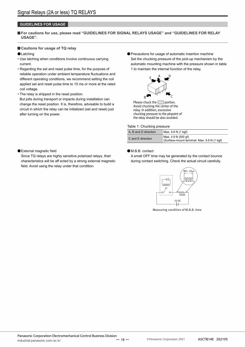
Please chuck the portion.Avoid chucking the center of the relay. In addition, excessive chucking pressure to the pinpoint of the relay should be also avoided.
E A
C
D
B
GUIDELINES FOR USAGE
For cautions for use, please read “GUIDELINES FOR SIGNAL RELAYS USAGE” and “GUIDELINES FOR RELAY USAGE”.
Cautions for usage of TQ relay Latching
• Use latching when conditions involve continuous carrying current.
• Regarding the set and reset pulse time, for the purpose of reliable operation under ambient temperature fluctuations and different operating conditions, we recommend setting the coil applied set and reset pulse time to 10 ms or more at the rated coil voltage.
• The relay is shipped in the reset position. But jolts during transport or impacts during installation can change the reset position. It is, therefore, advisable to build a circuit in which the relay can be initialized (set and reset) just after turning on the power.
Precautions for usage of automatic insertion machineSet the chucking pressure of the pick-up mechanism by the automatic mounting machine with the pressure shown in table 1 to maintain the internal function of the relay.
Table 1: Chucking pressureA, B and D direction Max. 9.8 N (1 kgf)
C and E direction Max. 4.9 N (500 gf) (Surface-mount terminal: Max. 9.8 N (1 kgf)
5V DC
Min. 10µs
500Ω
Measuring condition of M.B.B. time
External magnetic fieldSince TQ relays are highly sensitive polarized relays, their characteristics will be aff ected by a strong external magnetic field. Avoid using the relay under that condition.
M.B.B. contactA small OFF time may be generated by the contact bounce during contact switching. Check the actual circuit carefully.
ー 16 ー
Panasonic Corporation Electromechanical Control Business Divisionindustrial.panasonic.com/ac/e/ Panasonic Corporation 2021 ASCTB414E 202104
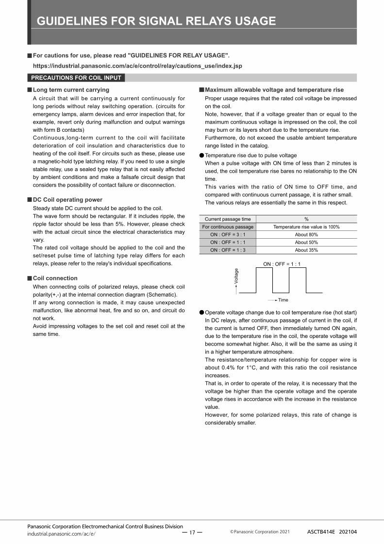
ON : OFF = 1 : 1
Volta
ge
Time
GUIDELINES FOR SIGNAL RELAYS USAGE
PRECAUTIONS FOR COIL INPUT
For cautions for use, please read "GUIDELINES FOR RELAY USAGE". https://industrial.panasonic.com/ac/e/control/relay/cautions_use/index.jsp
Long term current carryingA circuit that will be carrying a current continuously for long periods without relay switching operation. (circuits for emergency lamps, alarm devices and error inspection that, for example, revert only during malfunction and output warnings with form B contacts) Continuous,long-term current to the coil will facilitate deterioration of coil insulation and characteristics due to heating of the coil itself. For circuits such as these, please use a magnetic-hold type latching relay. If you need to use a single stable relay, use a sealed type relay that is not easily affected by ambient conditions and make a failsafe circuit design that considers the possibility of contact failure or disconnection.
DC Coil operating powerSteady state DC current should be applied to the coil. The wave form should be rectangular. If it includes ripple, the ripple factor should be less than 5%. However, please check with the actual circuit since the electrical characteristics may vary. The rated coil voltage should be applied to the coil and the set/reset pulse time of latching type relay differs for each relays, please refer to the relay's individual specifications.
Coil connectionWhen connecting coils of polarized relays, please check coil polarity(+,-) at the internal connection diagram (Schematic). If any wrong connection is made, it may cause unexpected malfunction, like abnormal heat, fire and so on, and circuit do not work.Avoid impressing voltages to the set coil and reset coil at the same time.
Maximum allowable voltage and temperature riseProper usage requires that the rated coil voltage be impressed on the coil.Note, however, that if a voltage greater than or equal to the maximum continuous voltage is impressed on the coil, the coil may burn or its layers short due to the temperature rise.Furthermore, do not exceed the usable ambient temperature range listed in the catalog.
Temperature rise due to pulse voltageWhen a pulse voltage with ON time of less than 2 minutes is used, the coil temperature rise bares no relationship to the ON time. This varies with the ratio of ON time to OFF time, and compared with continuous current passage, it is rather small. The various relays are essentially the same in this respect.
Operate voltage change due to coil temperature rise (hot start)In DC relays, after continuous passage of current in the coil, if the current is turned OFF, then immediately turned ON again, due to the temperature rise in the coil, the operate voltage will become somewhat higher. Also, it will be the same as using it in a higher temperature atmosphere.The resistance/temperature relationship for copper wire is about 0.4% for 1°C, and with this ratio the coil resistance increases.That is, in order to operate of the relay, it is necessary that the voltage be higher than the operate voltage and the operate voltage rises in accordance with the increase in the resistance value.However, for some polarized relays, this rate of change is considerably smaller.
Current passage time %For continuous passage Temperature rise value is 100%
ON : OFF = 3 : 1 About 80%ON : OFF = 1 : 1 About 50%ON : OFF = 1 : 3 About 35%
ー 17 ー

GUIDELINES FOR RELAY USAGE
Panasonic Corporation Electromechanical Control Business Divisionindustrial.panasonic.com/ac/e/ Panasonic Corporation 2021 ASCTB414E 202104
5
85
Humidity (% RH)
Avoid icingwhen used attemperatureslower than 0°C
Avoid con-densation when used at tem-peratures higher than 0°C
Allowable range
Ambient temperature (℃)0 85-40
NOTES
Usage, Storage, and Transport ConditionsDuring usage, storage, or transportation, avoid locations subject to direct sunlight and maintain normal temperature, humidity, and pressure conditions.The allowable specifications for environments suitable for usage, storage, and transportation are given below.
1) Temperature: The allowable temperature range differs for each relay, so refer to the relay’s individual specifications. In addition, when transporting or storing relays while they are tube packaged, there are cases when the temperature may differ from the allowable range. In this situation, be sure to consult the individual specifications.
2) Humidity: 5 to 85% RHThe humidity range varies with the temperature. Use within the range indicated in the graph. (The allowable temperature depends on the relays.)
3) Pressure: 86 to 106 kPa
CondensationCondensation occurs when the ambient temperature drops suddenly from a high temperature and humidity, or the relay and microwave device is suddenly transferred from a low ambient temperature to a high temperature and humidity.Condensation causes the failures like insulation deterioration, wire disconnection and rust etc.Panasonic Corporation does not guarantee the failures caused by condensation.The heat conduction by the equipment may accelerate the cooling of device itself, and the condensation may occur.Please conduct product evaluations in the worst condition of the actual usage. (Special attention should be paid when high temperature heating parts are close to the device. Also please consider the condensation may occur inside of the device.)
IcingCondensation or other moisture may freeze on relays when the temperature become lower than 0°C.This icing causes the sticking of movable portion, the operation delay and the contact conduction failure etc. Panasonic Corporation does not guarantee the failures caused by the icing.The heat conduction by the equipment may accelerate the cooling of relay itself and the icing may occur.Please conduct product evaluations in the worst condition of the actual usage.
Low temperature and low humidityThe plastic becomes brittle if the switch is exposed to a low temperature, low humidity environment for long periods of time.
High temperature and high humidityStorage for extended periods of time (including transportation periods) at high temperature or high humidity levels or in atmospheres with organic gases or sulfide gases may cause a sulfide film or oxide film to form on the surfaces of the contacts and/or it may interfere with the functions. Check out the atmosphere in which the units are to be stored and transported.
PackageIn terms of the packing format used, make every effort to keep the effects of moisture, organic gases and sulfide gases to the absolute minimum.
ー 18 ー
GUIDELINES FOR RELAY USAGE
Panasonic Corporation Electromechanical Control Business Divisionindustrial.panasonic.com/ac/e/ Panasonic Corporation 2021 ASCTB414E 202104
5% 10% 60%
Spot
Humidity indicator card
SiliconWhen a source of silicone substances (silicone rubber, silicone oil,silicone coating materials and silicone filling materials etc.) is used around the relay, the silicone gas (low molecular siloxane etc.) may be produced This silicone gas may penetrate into the inside of the relay. When the relay is kept and used in this condition, silicone compound may adhere to the relay contacts which may cause the contact failure. Do not use any sources of silicone gas around the relay (Including plastic seal types).
NOx GenerationWhen relay is used in an atmosphere high in humidity to switch a load which easily produces an arc, the NOx created by the arc and the water absorbed from outside the relay combine to produce nitric acid.This corrodes the internal metal parts and adversely affects operation.Avoid use at an ambient humidity of 85% RH or higher (at 20°C). If use at high humidity is unavoidable, please contact our sales representative.
5% 10% 60% Bake treatment necessity judgment
Ⅰ ● ● ● No need to bakeⅡ ○ ● ● No need to bakeⅢ ○ ○ ● Need to bakeⅣ ○ ○ ○ Need to bake
Storage requirementsSince the surface-mount terminal type is sensitive to humidity it is packaged with tightly sealed anti-humidity packaging. However, when storing, please be careful of the following.
1) Please use promptly once the anti-humidity pack is opened.(within 72 hours, Max. 30°C / 70% RH). If left with the pack open, the relay will absorb moisture which will cause thermal stress when reflow mounting and thus cause the case to expand. As a result, the seal may break.
2) If relays will not be used within 72 hours, please store relays in a humidity controlled desiccator or in an anti-humidity bag to which silica gel has been added.* If the relay is to be soldered after it has been exposed to excessive humidity
atmosphere, cracks and leaks can occur. Be sure to mount the relay under the required mounting conditions.
3) When relays (which is packaged with humidity indicator and silica gel) meeting one of below criteria, please bake (dry) before use.
<Baking (Drying) conditions>With reel : 45°C, 96 hours or more.
Without reel (including relay only) : 60°C, 35 hours or more.
● : indicate brown, ○ : Other than brown (blueish color)
4) The following cautionary label is affixed to the anti-humidity
pack.
When the storage conditions specified in 1) are exceeded. When humidity indicator is in Ⅲ or Ⅳ status according to judgement standard.
<How to judge>Please check humidity indicator color and decide if baking is necessary or not.
ー 19 ー
GUIDELINES FOR RELAY USAGE
Panasonic Corporation Electromechanical Control Business Divisionindustrial.panasonic.com/ac/e/ Panasonic Corporation 2021 ASCTB414E 202104
OTHERS
Cleaning1) Although the environmentally sealed type relay (plastic sealed
type,etc.) can be cleaned, avoid immersing the relay into cold liquid (such as cleaning solvent) immediately after soldering. Doing so may deteriorate the sealing performance.
2) Surface-mount terminal type relay is sealed type and it can be cleaned by immersion. Use pure water or alcohol-based cleaning solvent.
3) Cleaning with the boiling method is recommended (The temperature of cleaning liquid should be 40°C or lower). Avoid ultrasonic cleaning on relays. Use of ultrasonic cleaning may cause breaks in the coil or slight sticking of the contacts due to the ultrasonic energy.
Please refer to "the latest product specifications"when designing your product.•Requests to customers:https://industrial.panasonic.com/ac/e/salespolicies/
ー 20 ー

Please contact ..........
Electromechanical Control Business Division
industral.panasonic.com/ac/e/
Specifications are subject to change without notice.
1006, Oaza Kadoma, Kadoma-shi, Osaka 571-8506, Japan
©Panasonic Corporation 2021
ASCTB14E 202105


![[ 3000 Series Time Delay Relays and Measuring Relays ... · [ 3000 Series Time Delay Relays and Measuring Relays ] ... Measuring Relays ] • Time Delay Relays ... Dear Reader, Dear](https://img.pdfslide.net/doc/110x75/5b85683b7f8b9aec488e43dd/-3000-series-time-delay-relays-and-measuring-relays-3000-series-time.jpg)