Embed Size (px)
Citation preview
USER GUIDE
FLAT ROOFDESIGN ASSISTANT™
2
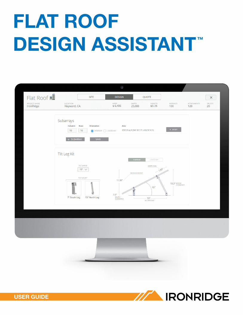
GET STARTED
1. START DESIGN ASSISTANT
Go to the IronRidge home page at ironridge.com, then hover over the "Flat Roofs" menu at the top and click the blue "Design Assistant" button.
2. SIGN UP FOR AN ACCOUNT
If you don't have an account, click the blue sign up link at the bottom of the page. If you already have an account click the sign in link.
í Having a Design Assistant account allows you to save all of your quoted projects in one location, share projects with other Design Assistant users, and receive important updates.
3. FILL OUT AND SUBMIT FORM
Fill out the web form as required, agree to the IronRidge terms of service, and then click the "submit" button. You will then be logged into the Flat Roof Design Assistant.
4. CONFIRM YOUR ACCOUNT
Click the "confirm my account" link in your confirmation email. You will be automatically signed in. Now you're ready to create a new project.
1
2
3
4
3
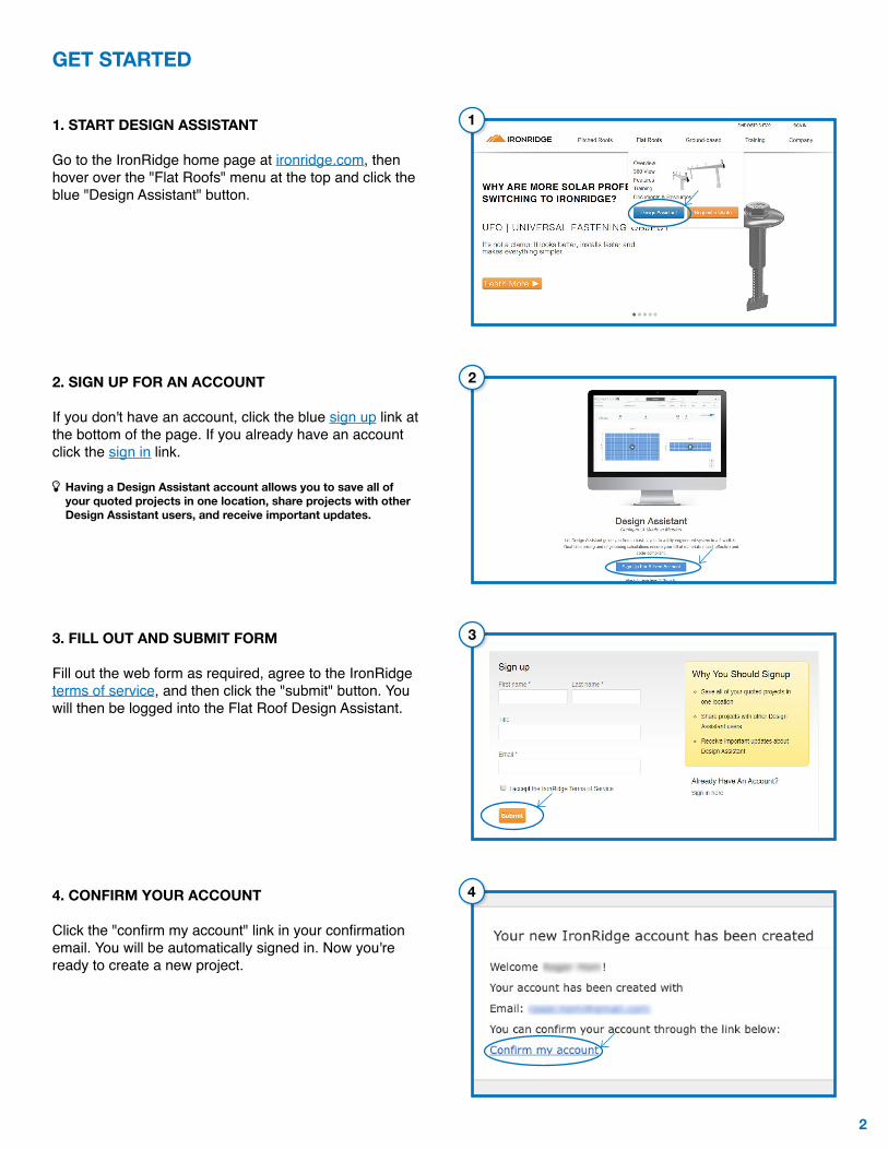
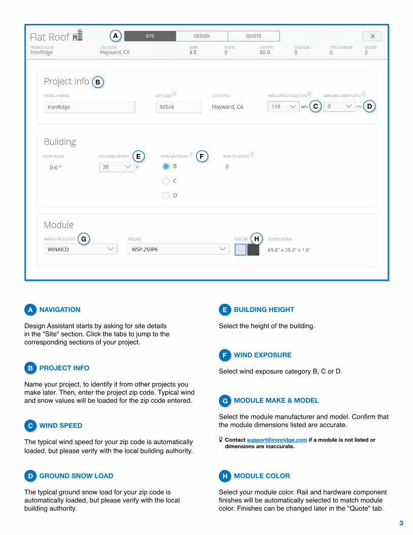
NAVIGATION Design Assistant starts by asking for site details in the "Site" section. Click the tabs to jump to the corresponding sections of your project.
PROJECT INFO Name your project, to identify it from other projects you make later. Then, enter the project zip code. Typical wind and snow values will be loaded for the zip code entered.
WIND SPEED The typical wind speed for your zip code is automatically loaded, but please verify with the local building authority.
GROUND SNOW LOAD The typical ground snow load for your zip code is automatically loaded, but please verify with the local building authority.
BUILDING HEIGHT Select the height of the building.
WIND EXPOSURE
Select wind exposure category B, C or D.
MODULE MAKE & MODEL
Select the module manufacturer and model. Confirm that the module dimensions listed are accurate.
í Contact [email protected] if a module is not listed or dimensions are inaccurate.
MODULE COLOR Select your module color. Rail and hardware component finishes will be automatically selected to match module color. Finishes can be changed later in the "Quote" tab.
B
HG
A
C D
E F
A
B
C
E
F
H
G
D
4
A
B
C
D
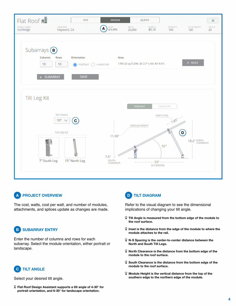
PROJECT OVERVIEW The cost, watts, cost per watt, and number of modules, attachments, and splices update as changes are made.
SUBARRAY ENTRY Enter the number of columns and rows for each subarray. Select the module orientation, either portrait or landscape.
TILT ANGLE Select your desired tilt angle.
í Flat Roof Design Assistant supports a tilt angle of 4-30° for portrait orientation, and 6-30° for landscape orientation.
TILT DIAGRAM Refer to the visual diagram to see the dimensional implications of changing your tilt angle.
í Tilt Angle is measured from the bottom edge of the module to the roof surface.
í Inset is the distance from the edge of the module to where the module attaches to the rail.
í N-S Spacing is the center-to-center distance between the North and South Tilt Legs.
í North Clearance is the distance from the bottom edge of the module to the roof surface.
í South Clearance is the distance from the bottom edge of the module to the roof surface.
í Module Height is the vertical distance from the top of the southern edge to the northern edge of the module.
A
B
C
D
5
E
G
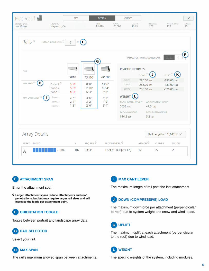
ATTACHMENT SPAN Enter the attachment span.
í Larger attachment spans reduce attachments and roof penetrations, but but may require larger rail sizes and will increase the loads per attachment point.
ORIENTATION TOGGLE Toggle between portrait and landscape array data.
RAIL SELECTOR Select your rail.
MAX SPAN The rail’s maximum allowed span between attachments.
MAX CANTILEVER The maximum length of rail past the last attachment.
DOWN (COMPRESSIVE) LOAD The maximum downforce per attachment (perpendicular to roof) due to system weight and snow and wind loads.
UPLIFT The maximum uplift at each attachment (perpendicular to the roof) due to wind load.
WEIGHT
The specific weights of the system, including modules.
L
E
F
I
K
J
G
J
H
I
F
H
K
L
6
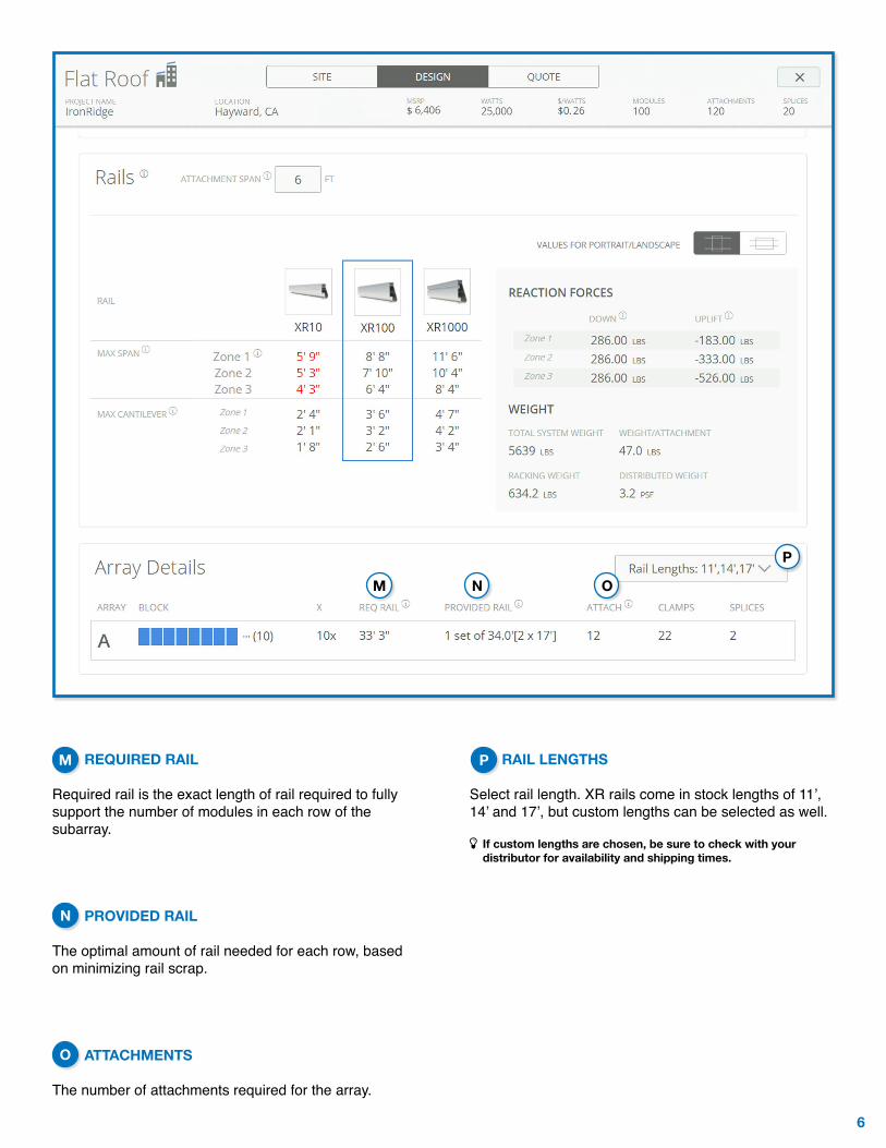
REQUIRED RAIL Required rail is the exact length of rail required to fully support the number of modules in each row of the subarray.
PROVIDED RAIL The optimal amount of rail needed for each row, based on minimizing rail scrap.
ATTACHMENTS
The number of attachments required for the array.
RAIL LENGTHS Select rail length. XR rails come in stock lengths of 11’, 14’ and 17’, but custom lengths can be selected as well.
í If custom lengths are chosen, be sure to check with your distributor for availability and shipping times.
M
N
P
O
M N O
P
7
A
B
C
D
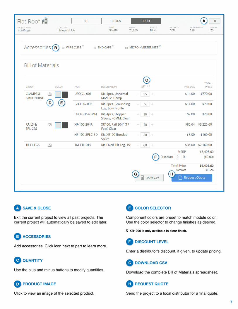
SAVE & CLOSE Exit the current project to view all past projects. The current project will automatically be saved to edit later.
ACCESSORIES Add accessories. Click icon next to part to learn more.
QUANTITY Use the plus and minus buttons to modify quantities.
PRODUCT IMAGE Click to view an image of the selected product.
COLOR SELECTOR Component colors are preset to match module color. Use the color selector to change finishes as desired.
í XR1000 is only available in clear finish.
DISCOUNT LEVEL Enter a distributor's discount, if given, to update pricing.
DOWNLOAD CSV
Download the complete Bill of Materials spreadsheet.
REQUEST QUOTE Send the project to a local distributor for a final quote.
A
B
C
E
F
H
G
F
H
E
D
G
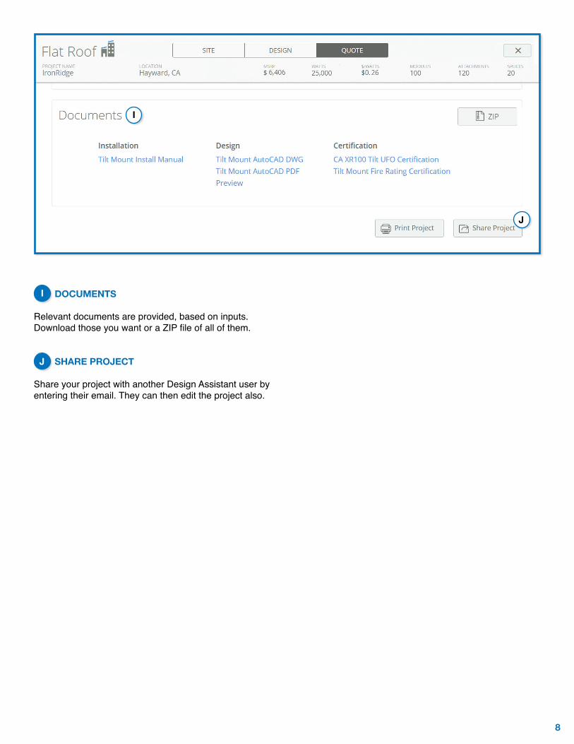
8
DOCUMENTS Relevant documents are provided, based on inputs. Download those you want or a ZIP file of all of them.
SHARE PROJECT
Share your project with another Design Assistant user by entering their email. They can then edit the project also.
I
J
I
J
IronRidge.com/design
© 2016 IRONRIDGE, INC. U.S. PATENT 8,826,163. VERSION 1.10