Embed Size (px)
Citation preview
Flaw Tolerance Assessments for ISI Relief
Request on Weldment of Main Steam Line
Branch Connection Weldolets
Jun-Seog Yang (Korea Hydro & Nuclear Power Co., Ltd)
Nam-Su Huh (SEOULTECH)
Yun-Jae Kim (Korea University)
1st KEPIC/ASME Joint Seminar on
In-service Inspection (ASME BPV XI / KEPIC-MI)
September 5, 2017
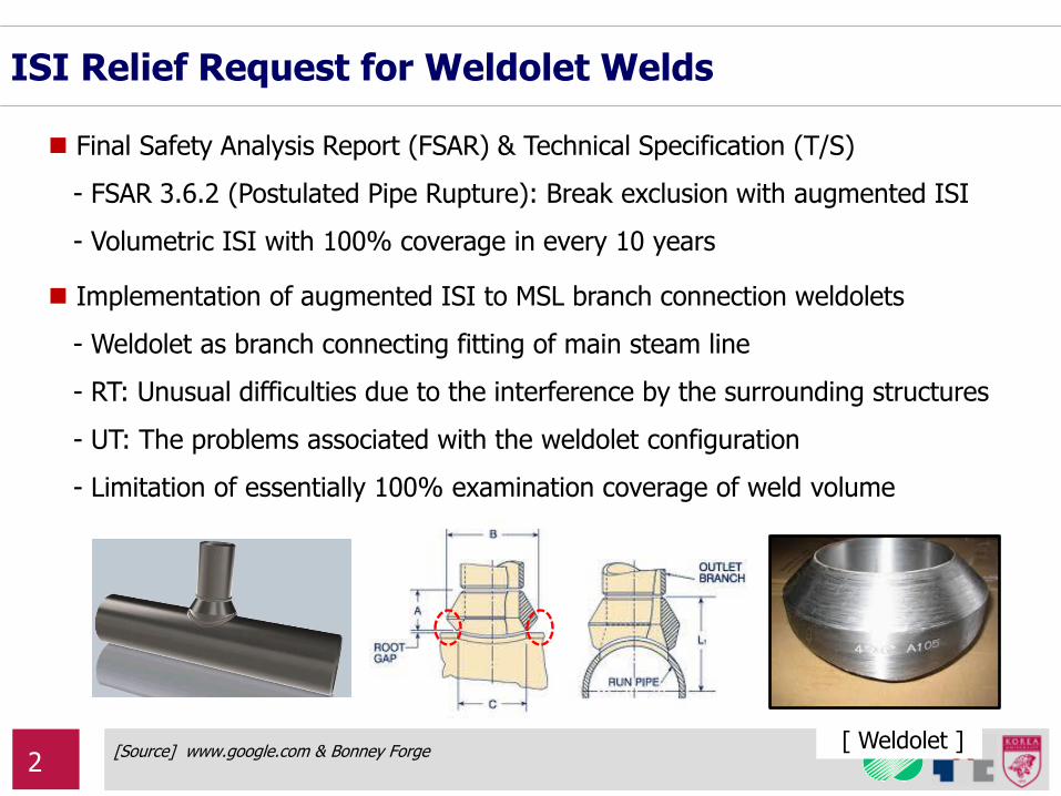
ISI Relief Request for Weldolet Welds
[Source] www.google.com & Bonney Forge [ Weldolet ]
Implementation of augmented ISI to MSL branch connection weldolets
- Weldolet as branch connecting fitting of main steam line
- RT: Unusual difficulties due to the interference by the surrounding structures
- UT: The problems associated with the weldolet configuration
- Limitation of essentially 100% examination coverage of weld volume
Final Safety Analysis Report (FSAR) & Technical Specification (T/S)
- FSAR 3.6.2 (Postulated Pipe Rupture): Break exclusion with augmented ISI
- Volumetric ISI with 100% coverage in every 10 years
2
Objectives
Alternative approaches for the ISI relief request for weldolet welds
- UT with various transducers as for non-destructive examination
- Probabilistic safety analysis
- Flaw tolerance assessment based on the deterministic fracture mechanics
(This presentation)
3
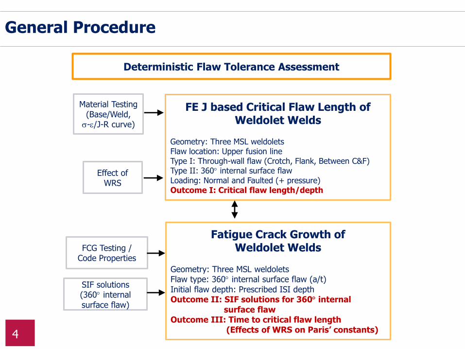
General Procedure
Deterministic Flaw Tolerance Assessment
Material Testing (Base/Weld, -/J-R curve)
Fatigue Crack Growth of Weldolet Welds
Geometry: Three MSL weldolets Flaw type: 360 internal surface flaw (a/t) Initial flaw depth: Prescribed ISI depth Outcome II: SIF solutions for 360 internal surface flaw Outcome III: Time to critical flaw length (Effects of WRS on Paris’ constants)
FE J based Critical Flaw Length of Weldolet Welds
Geometry: Three MSL weldolets Flaw location: Upper fusion line Type I: Through-wall flaw (Crotch, Flank, Between C&F) Type II: 360 internal surface flaw Loading: Normal and Faulted (+ pressure) Outcome I: Critical flaw length/depth
FCG Testing / Code Properties
Effect of WRS
SIF solutions (360 internal surface flaw)
4
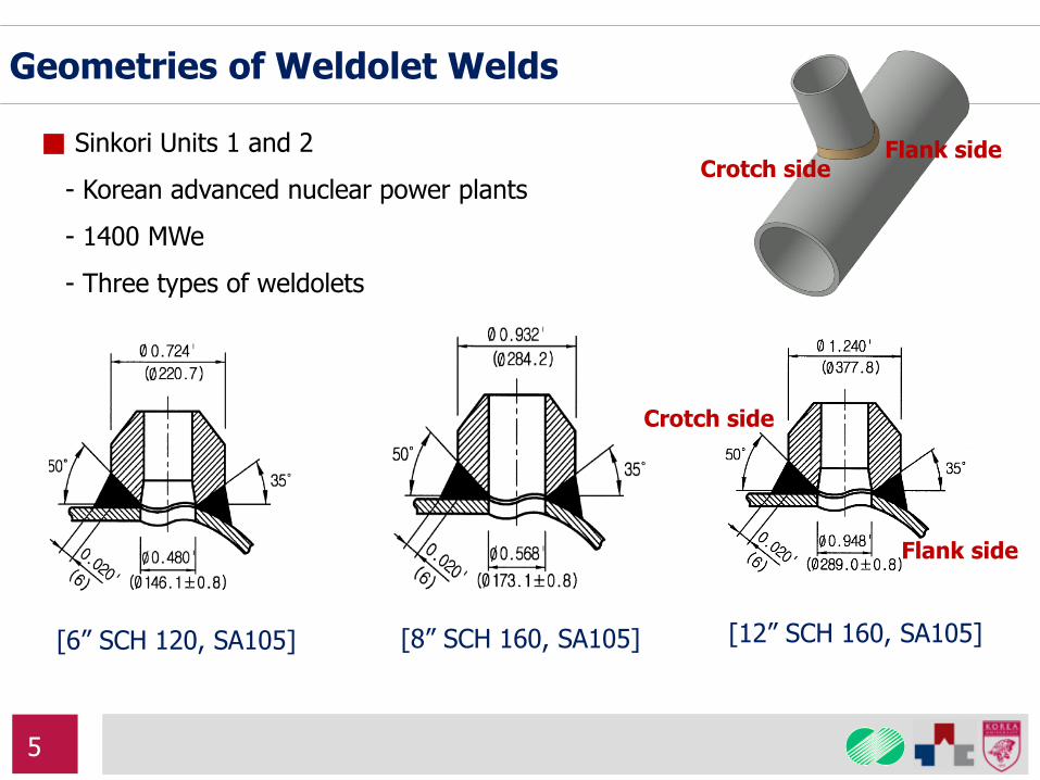
Geometries of Weldolet Welds
[6” SCH 120, SA105] [8” SCH 160, SA105] [12” SCH 160, SA105]
■ Sinkori Units 1 and 2
- Korean advanced nuclear power plants
- 1400 MWe
- Three types of weldolets
Flank side
Crotch side
Crotch side Flank side
5
1
2
3
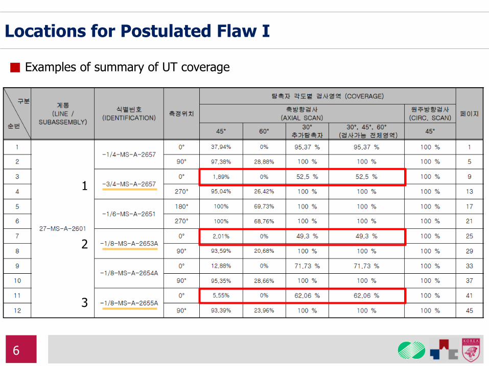
Locations for Postulated Flaw I
■ Examples of summary of UT coverage
6
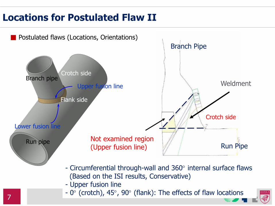
Not examined region (Upper fusion line) Run Pipe
Branch Pipe
Weldment
Crotch side
Flank side
Upper fusion line
Lower fusion line
Run pipe
Branch pipe
- Circumferential through-wall and 360 internal surface flaws (Based on the ISI results, Conservative) - Upper fusion line - 0 (crotch), 45, 90 (flank): The effects of flaw locations
Crotch side
Locations for Postulated Flaw II
■ Postulated flaws (Locations, Orientations)
7

Flaw Location
Weld Zone
Upper fusion
line flaw
Projected flaw
Main Pipe
Main Pipe
Maximum K
■ Upper fusion line flaw vs. Run pipe OD surface flaw (Branch weldolet)
- Comparisons of stress intensity factors according to the flaw locations
Flaw is postulated along the upper fusion line
Locations for Postulated Flaw III
Projected flaw
Upper fusion line flaw
8
Ro
Rm Ri
t
① 50°
②
Ri
Ro
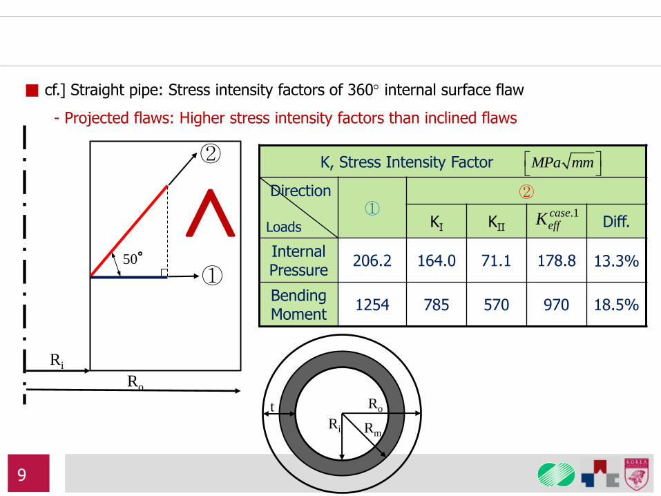
K, Stress Intensity Factor
Direction
Loads
① ②
KI KII Diff.
Internal Pressure
206.2 164.0 71.1 178.8 13.3%
Bending Moment
1254 785 570 970 18.5%
MPa mm
.1caseeffK
■ cf.] Straight pipe: Stress intensity factors of 360 internal surface flaw
- Projected flaws: Higher stress intensity factors than inclined flaws
9
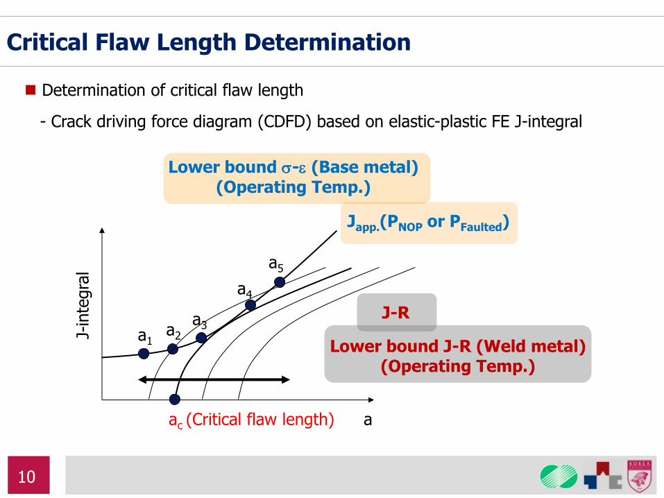
Critical Flaw Length Determination
Determination of critical flaw length
- Crack driving force diagram (CDFD) based on elastic-plastic FE J-integral
J-in
tegra
l
a ac (Critical flaw length)
J-R
Japp.(PNOP or PFaulted)
a1 a2
a3
a4
a5
Lower bound - (Base metal) (Operating Temp.)
Lower bound J-R (Weld metal) (Operating Temp.)
10
Upper fusion line
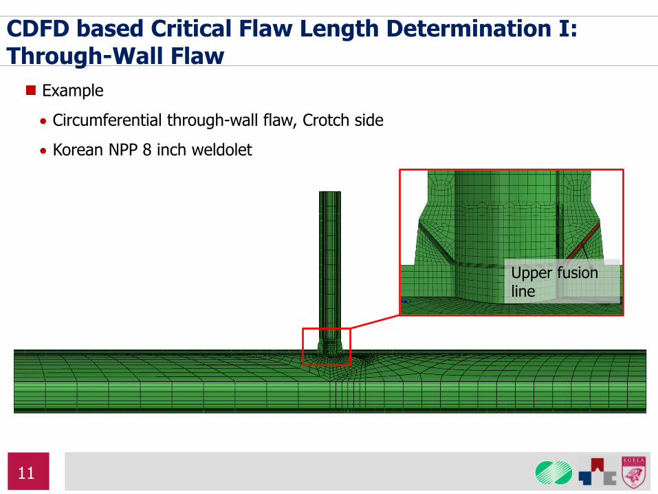
CDFD based Critical Flaw Length Determination I: Through-Wall Flaw
Example
Circumferential through-wall flaw, Crotch side
Korean NPP 8 inch weldolet
11
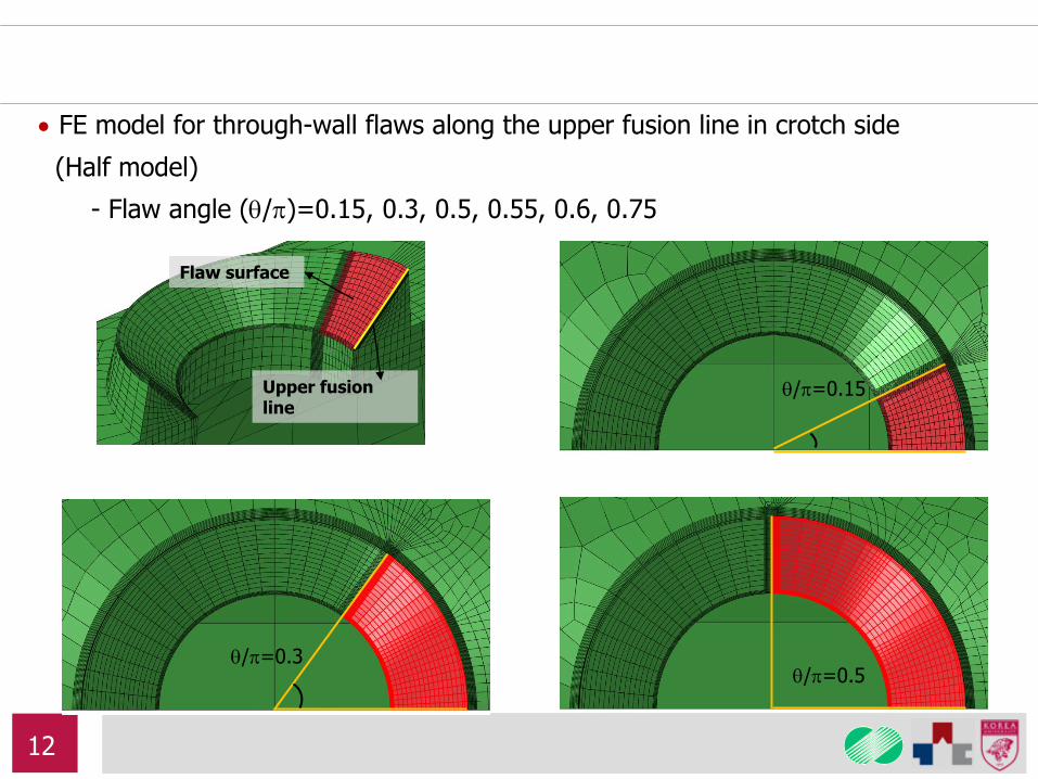
FE model for through-wall flaws along the upper fusion line in crotch side
(Half model)
- Flaw angle (/)=0.15, 0.3, 0.5, 0.55, 0.6, 0.75
Upper fusion line
Flaw surface
/=0.15
/=0.3 /=0.5
12
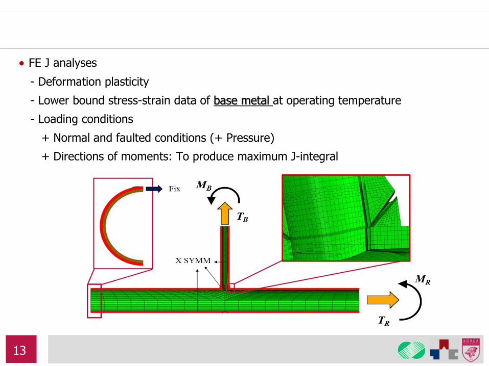
FE J analyses
- Deformation plasticity
- Lower bound stress-strain data of base metal at operating temperature
- Loading conditions
+ Normal and faulted conditions (+ Pressure)
+ Directions of moments: To produce maximum J-integral
13
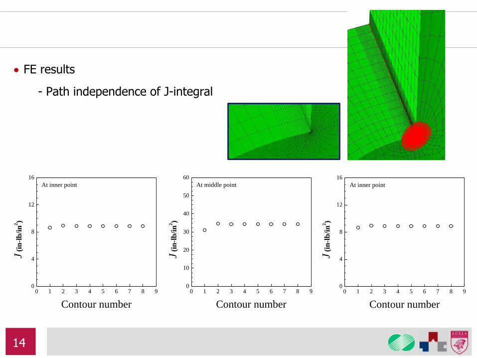
FE results
- Path independence of J-integral
0 1 2 3 4 5 6 7 8 90
4
8
12
16
At inner point
J (i
n-l
b/i
n2)
Contour number
0 1 2 3 4 5 6 7 8 90
10
20
30
40
50
60
At middle point
J (i
n-l
b/i
n2)
Contour number
0 1 2 3 4 5 6 7 8 90
4
8
12
16
At inner point
J (i
n-l
b/i
n2)
Contour number
14
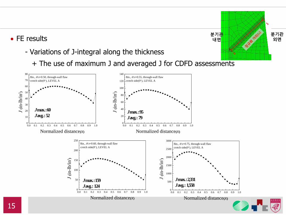
FE results
- Variations of J-integral along the thickness
+ The use of maximum J and averaged J for CDFD assessments
J max. : 60
J avg. : 52 J max. : 95
J avg. : 79
J max. : 159
J avg. : 124
J max. : 2,331
J avg. : 1,558
0.0 0.1 0.2 0.3 0.4 0.5 0.6 0.7 0.8 0.9 1.00
500
1000
1500
2000
2500
3000
8in., /=0.75, through-wall flaw
crotch side(0), LEVEL A
J (i
n-l
b/i
n2)
Normalized distance(x)
0.0 0.1 0.2 0.3 0.4 0.5 0.6 0.7 0.8 0.9 1.00
50
100
150
200
250
8in., /=0.60, through-wall flaw
crotch side(0), LEVEL A
J (i
n-l
b/i
n2)
Normalized distance(x)
0.0 0.1 0.2 0.3 0.4 0.5 0.6 0.7 0.8 0.9 1.00
20
40
60
80
100
120
140
8in., /=0.55, through-wall flaw
crotch side(0), LEVEL A
J (i
n-l
b/i
n2)
Normalized distance(x)
0.0 0.1 0.2 0.3 0.4 0.5 0.6 0.7 0.8 0.9 1.00
10
20
30
40
50
60
70
80
8in., /=0.50, through-wall flaw
crotch side(0), LEVEL A
J (i
n-l
b/i
n2)
Normalized distance(x)
15
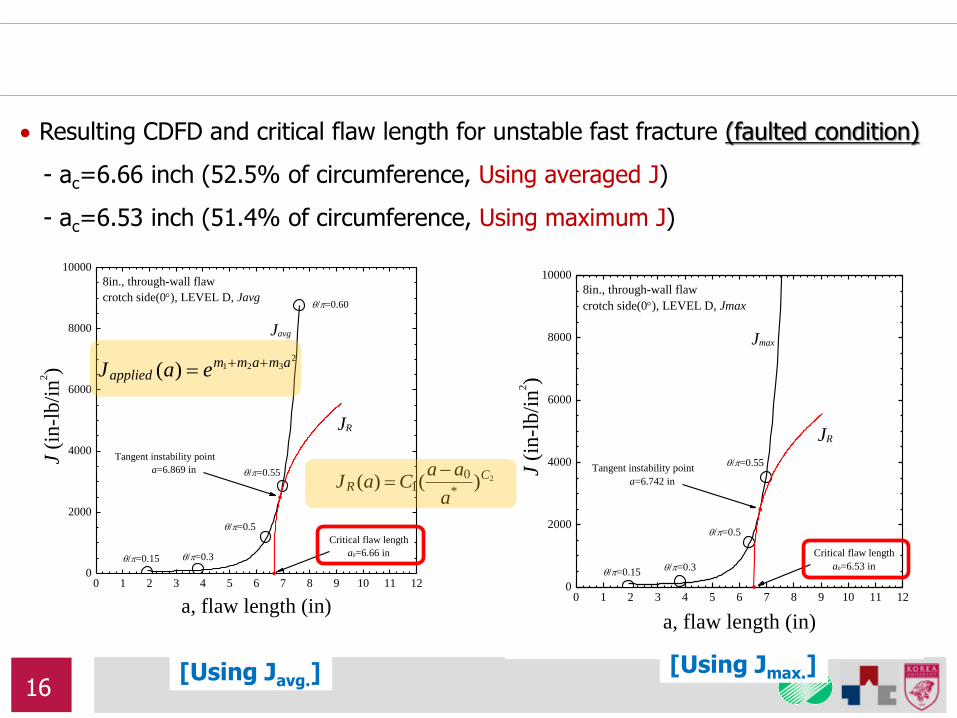
0 1 2 3 4 5 6 7 8 9 10 11 120
2000
4000
6000
8000
10000
/=0.60
8in., through-wall flaw
crotch side(0), LEVEL D, Javg
J (i
n-l
b/i
n2)
a, flaw length (in)
/=0.55
/=0.15
/=0.5
/=0.3
JR
Javg
Critical flaw length
a0=6.66 in
Tangent instability point
a=6.869 in
0 1 2 3 4 5 6 7 8 9 10 11 120
2000
4000
6000
8000
10000
8in., through-wall flaw
crotch side(0), LEVEL D, Jmax
J (i
n-l
b/i
n2)
a, flaw length (in)
/=0.55
/=0.5
/=0.3/=0.15
Jmax
JR
Critical flaw length
a0=6.53 in
Tangent instability point
a=6.742 in
Resulting CDFD and critical flaw length for unstable fast fracture (faulted condition)
- ac=6.66 inch (52.5% of circumference, Using averaged J)
- ac=6.53 inch (51.4% of circumference, Using maximum J)
2321)( amamm
applied eaJ
2)()(*
01
CR
a
aaCaJ
[Using Javg.] [Using Jmax.] 16

A
A’
A A’
Upper fusion line
Flaw Surface
Example
360 internal surface flaw
Korean NPP 8 inch weldolet
CDFD based Critical Flaw Length Determination II: 360 Internal Surface Flaw
17
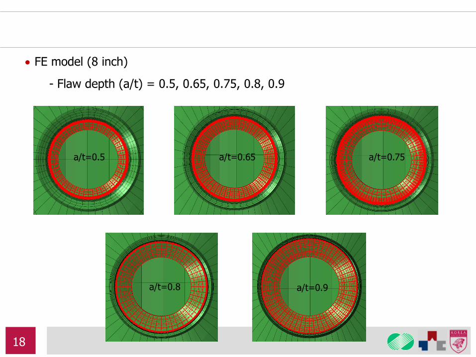
a/t=0.5 a/t=0.65 a/t=0.75
a/t=0.9 a/t=0.8
FE model (8 inch)
- Flaw depth (a/t) = 0.5, 0.65, 0.75, 0.8, 0.9
18
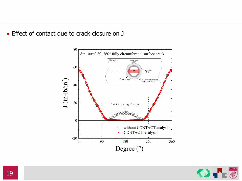
Effect of contact due to crack closure on J
19
1.6 1.8 2.0 2.2 2.4 2.6 2.8 3.00
500
1000
1500
2000
2500
3000
3500
4000
J (i
n-l
b/i
n2)
a, flaw depth (in)
8in., 360 fully circumferential surface flaw
Jmax
Tangent instability point
a=3.01 in
a/t=0.50 a/t=0.65 a/t=0.75 a/t=0.80
a/t=0.90J
R
Critical flaw depth
a0=2.97 in
3.11 inch
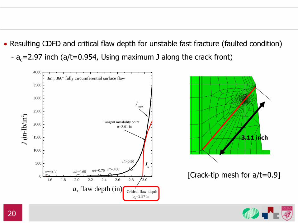
Resulting CDFD and critical flaw depth for unstable fast fracture (faulted condition)
- ac=2.97 inch (a/t=0.954, Using maximum J along the crack front)
[Crack-tip mesh for a/t=0.9]
20
Through-wall flaws (percentage of the circumference)
- 6 & 8 inch: about 50% (faulted) ~ 70% (normal)
- 12 inch: about 45% (faulted) ~ 55% (normal)
- The effects of flaw locations (crotch, flank, middle): Not significant
360 internal surface flaws
- 6, 8, & 12 inch: over a/t=0.9 (both normal and faulted)
Summary of Critical Flaw Length Determinations
21
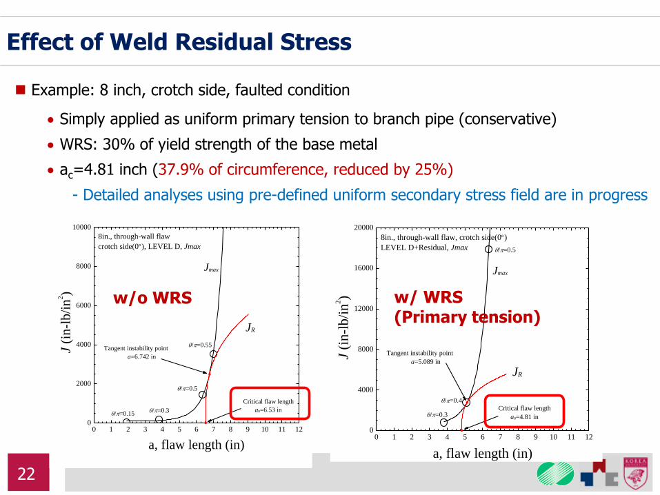
Example: 8 inch, crotch side, faulted condition
Simply applied as uniform primary tension to branch pipe (conservative)
WRS: 30% of yield strength of the base metal
ac=4.81 inch (37.9% of circumference, reduced by 25%)
- Detailed analyses using pre-defined uniform secondary stress field are in progress
0 1 2 3 4 5 6 7 8 9 10 11 120
4000
8000
12000
16000
20000
J (i
n-l
b/i
n2)
a, flaw length (in)
Jmax
/=0.5
/=0.4
/=0.3
JR
Tangent instability point
a=5.089 in
Critical flaw length
a0=4.81 in
8in., through-wall flaw, crotch side(0)
LEVEL D+Residual, Jmax
Effect of Weld Residual Stress
0 1 2 3 4 5 6 7 8 9 10 11 120
2000
4000
6000
8000
10000
8in., through-wall flaw
crotch side(0), LEVEL D, Jmax
J (i
n-l
b/i
n2)
a, flaw length (in)
/=0.55
/=0.5
/=0.3/=0.15
Jmax
JR
Critical flaw length
a0=6.53 in
Tangent instability point
a=6.742 in
w/o WRS w/ WRS (Primary tension)
22
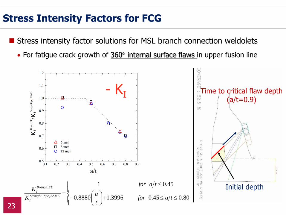
Initial depth
Time to critical flaw depth (a/t=0.9)
For fatigue crack growth of 360 internal surface flaws in upper fusion line
Stress intensity factor solutions for MSL branch connection weldolets
Stress Intensity Factors for FCG
,
,
1 0.45
0.8880 1.3996 0.45 0.80
Branch FE
I
Straight Pipe ASME
I
for a tK
afor a tK
t
- KI
23
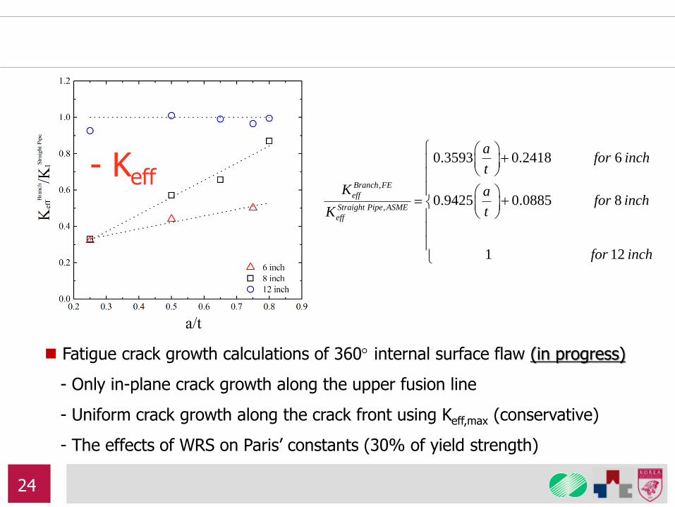
,
,
0.3593 0.2418 6
0.9425 0.0885 8
1 12
Branch FE
eff
Straight Pipe ASME
eff
afor inch
t
K afor inch
tK
for inch
- Keff
Fatigue crack growth calculations of 360 internal surface flaw (in progress)
- Only in-plane crack growth along the upper fusion line
- Uniform crack growth along the crack front using Keff,max (conservative)
- The effects of WRS on Paris’ constants (30% of yield strength)
24