Embed Size (px)
Citation preview

FLENDER supplies
Gear-rim system
for DMG2 gear unit
Assembly instructionsMA 5150.1 EN 12/2010

2 / 34MA 5150.1 EN 12/2010
Gear-rim system
for DMG2 gear unit
Assembly instructions
Translation of the original assembly instructions
Technical data
Spare parts,customer service
Maintenanceand repair
Faults, causesand remedy
Operation
Startup
Fitting
Technicaldescription
Transport andstorage
Safety instructions
General notes
1
11
10
9
8
7
6
5
4
3
2

3 / 34MA 5150.1 EN 12/2010
Notes and symbols in these assembly and operating instructions
Note: The term "Assembly and operating instructions" will in the following also be shortened to "instructions"or "manual".
Legal notes
Warning-note concept
This manual comprises notes which must be observed for your personal safety and for preventing material damage.Notes for your personal safety are marked with a warning triangle or an "Ex" symbol (when applyingDirective 94/9/EC), those only for preventing material damage with a "STOP" sign.
WARNING! Imminent explosion!
The notes indicated by this symbol are given to prevent explosion damage.Disregarding these notes may result in serious injury or death.
WARNING! Imminent personal injury!
The notes indicated by this symbol are given to prevent personal injury.Disregarding these notes may result in serious injury or death.
WARNING! Imminent damage to the product!
The notes indicated by this symbol are given to prevent damage to the product.Disregarding these notes may result in material damage.
NOTE!
The notes indicated by this symbol must be treated as general operating information.Disregarding these notes may result in undesirable results or conditions.
WARNING! Hot surfaces!
The notes indicated by this symbol are made to prevent risk of burns due to hot surfacesand must always be observed.Disregarding these notes may result in light or serious injury.
Where there is more than one hazard, the warning note for whichever hazard is the most serious is always used.If in a warning note a warning triangle is used to warn of possible personal injury, a warning of material damage maybe added to the same warning note.
Qualified personnel
The product or system to which these instructions relate may be handled only by persons qualified for the workconcerned and in accordance with the instructions relating to the work concerned, particularly the safety andwarning notes contained in those instructions. Qualified personnel must be specially trained and have theexperience necessary to recognise risks associated with these products or systems and to avoid possible hazards.
4 / 34MA 5150.1 EN 12/2010
Intended use of Siemens products
Observe also the following:
Siemens products must be used only for the applications provided for in the catalogue and the relevanttechnical documentation. If products and components of other makes are used, they must berecommended or approved by Siemens. The faultfree, safe operation of the products calls for propertransport, proper storage, erection, assembly, installation, startup, operation and maintenance. Thepermissible ambient conditions must be adhered to. Notes in the relevant documentations must beobserved.
Trademarks
All designations indicated with the registered industrial property mark ® are registered trademarks of Siemens AG.Other designations used in these instructions may be trademarks the use of which by third parties for their ownpurposes may infringe holders’ rights.
Exclusion of liability
We have checked the content of the instructions for compliance with the hard and software described.Nevertheless, variances may occur, and so we can offer no warranty for complete agreement. The informationgiven in these instructions is regularly checked, and any necessary corrections are included in subsequent editions.
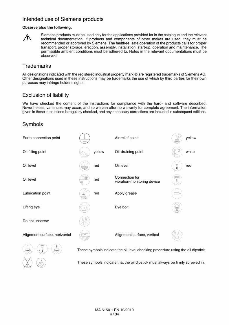
Symbols
Earth connection point Air relief point yellow
Oilfilling point yellow Oildraining point white
Oil level red Oil level red
Oil level redConnection forvibrationmonitoring device
Lubrication point red Apply grease
Lifting eye Eye bolt
Do not unscrew
Alignment surface, horizontal Alignment surface, vertical
These symbols indicate the oillevel checking procedure using the oil dipstick.
These symbols indicate that the oil dipstick must always be firmly screwed in.

5 / 34MA 5150.1 EN 12/2010
Contents
1. Technical data 7. . . . . . . . . . . . . . . . . . . . . . . . . . . . . . . . . . . . . . . . . . . . . . . . . . . . . . 1.1 General technical data 7. . . . . . . . . . . . . . . . . . . . . . . . . . . . . . . . . . . . . . . . . . . . . . . . . . . . . . . . . . . . . . .
1.2 Measuringsurface soundpressure level 7. . . . . . . . . . . . . . . . . . . . . . . . . . . . . . . . . . . . . . . . . . . . . . .
1.3 Weights 7. . . . . . . . . . . . . . . . . . . . . . . . . . . . . . . . . . . . . . . . . . . . . . . . . . . . . . . . . . . . . . . . . . . . . . . . . . .
2. General notes 8. . . . . . . . . . . . . . . . . . . . . . . . . . . . . . . . . . . . . . . . . . . . . . . . . . . . . . 2.1 Introduction 8. . . . . . . . . . . . . . . . . . . . . . . . . . . . . . . . . . . . . . . . . . . . . . . . . . . . . . . . . . . . . . . . . . . . . . . .
2.2 Copyright 8. . . . . . . . . . . . . . . . . . . . . . . . . . . . . . . . . . . . . . . . . . . . . . . . . . . . . . . . . . . . . . . . . . . . . . . . . .
3. Safety instructions 9. . . . . . . . . . . . . . . . . . . . . . . . . . . . . . . . . . . . . . . . . . . . . . . . . . 3.1 Obligations of the user 9. . . . . . . . . . . . . . . . . . . . . . . . . . . . . . . . . . . . . . . . . . . . . . . . . . . . . . . . . . . . . . .
3.2 Environmental protection 10. . . . . . . . . . . . . . . . . . . . . . . . . . . . . . . . . . . . . . . . . . . . . . . . . . . . . . . . . . . . .
3.3 Special dangers and personal protective equipment 10. . . . . . . . . . . . . . . . . . . . . . . . . . . . . . . . . . . . .
4. Transport and storage 11. . . . . . . . . . . . . . . . . . . . . . . . . . . . . . . . . . . . . . . . . . . . . . 4.1 Scope of supply 11. . . . . . . . . . . . . . . . . . . . . . . . . . . . . . . . . . . . . . . . . . . . . . . . . . . . . . . . . . . . . . . . . . . .
4.2 Transport 11. . . . . . . . . . . . . . . . . . . . . . . . . . . . . . . . . . . . . . . . . . . . . . . . . . . . . . . . . . . . . . . . . . . . . . . . . .
4.3 Storage of the gearrim system 12. . . . . . . . . . . . . . . . . . . . . . . . . . . . . . . . . . . . . . . . . . . . . . . . . . . . . . .
4.4 Standard coating and preservation 12. . . . . . . . . . . . . . . . . . . . . . . . . . . . . . . . . . . . . . . . . . . . . . . . . . . .
5. Technical description 13. . . . . . . . . . . . . . . . . . . . . . . . . . . . . . . . . . . . . . . . . . . . . . . 5.1 General description 13. . . . . . . . . . . . . . . . . . . . . . . . . . . . . . . . . . . . . . . . . . . . . . . . . . . . . . . . . . . . . . . . .
5.2 Gear rim 13. . . . . . . . . . . . . . . . . . . . . . . . . . . . . . . . . . . . . . . . . . . . . . . . . . . . . . . . . . . . . . . . . . . . . . . . . . .
5.3 Hood 13. . . . . . . . . . . . . . . . . . . . . . . . . . . . . . . . . . . . . . . . . . . . . . . . . . . . . . . . . . . . . . . . . . . . . . . . . . . . . .
5.4 Sealing system 14. . . . . . . . . . . . . . . . . . . . . . . . . . . . . . . . . . . . . . . . . . . . . . . . . . . . . . . . . . . . . . . . . . . . .
5.4.1 Function of the sealing system 14. . . . . . . . . . . . . . . . . . . . . . . . . . . . . . . . . . . . . . . . . . . . . . . . . . . . . . . .
5.4.1.1 Oil seal 14. . . . . . . . . . . . . . . . . . . . . . . . . . . . . . . . . . . . . . . . . . . . . . . . . . . . . . . . . . . . . . . . . . . . . . . . . . . .
5.4.1.2 Centrifugal ring 14. . . . . . . . . . . . . . . . . . . . . . . . . . . . . . . . . . . . . . . . . . . . . . . . . . . . . . . . . . . . . . . . . . . . .
5.4.1.3 Dust protection 14. . . . . . . . . . . . . . . . . . . . . . . . . . . . . . . . . . . . . . . . . . . . . . . . . . . . . . . . . . . . . . . . . . . . .
6. Fitting 15. . . . . . . . . . . . . . . . . . . . . . . . . . . . . . . . . . . . . . . . . . . . . . . . . . . . . . . . . . . . . . 6.1 General information on fitting 15. . . . . . . . . . . . . . . . . . . . . . . . . . . . . . . . . . . . . . . . . . . . . . . . . . . . . . . . .
6.2 Unpacking 16. . . . . . . . . . . . . . . . . . . . . . . . . . . . . . . . . . . . . . . . . . . . . . . . . . . . . . . . . . . . . . . . . . . . . . . . .
6.3 Fitting the twopart gear rim 17. . . . . . . . . . . . . . . . . . . . . . . . . . . . . . . . . . . . . . . . . . . . . . . . . . . . . . . . . .
6.3.1 Preparing the mill flange 17. . . . . . . . . . . . . . . . . . . . . . . . . . . . . . . . . . . . . . . . . . . . . . . . . . . . . . . . . . . . .
6.3.2 Preparing the gear rim 18. . . . . . . . . . . . . . . . . . . . . . . . . . . . . . . . . . . . . . . . . . . . . . . . . . . . . . . . . . . . . . .
6.3.3 First gearrim half 18. . . . . . . . . . . . . . . . . . . . . . . . . . . . . . . . . . . . . . . . . . . . . . . . . . . . . . . . . . . . . . . . . . .
6.3.4 Second gearrim half 18. . . . . . . . . . . . . . . . . . . . . . . . . . . . . . . . . . . . . . . . . . . . . . . . . . . . . . . . . . . . . . . .
6.3.5 Tightening the connecting elements on the part surfaces of the gear rim 18. . . . . . . . . . . . . . . . . . . .
6.3.5.1 Procedure of tightening the SUPERBOLT clamping elements 19. . . . . . . . . . . . . . . . . . . . . . . . . . . . .
6.3.5.2 Setting the gear rim 20. . . . . . . . . . . . . . . . . . . . . . . . . . . . . . . . . . . . . . . . . . . . . . . . . . . . . . . . . . . . . . . . .
6.3.6 Tightening torques and initialtensioning forces 22. . . . . . . . . . . . . . . . . . . . . . . . . . . . . . . . . . . . . . . . . .
6.4 Fitting and setting the type "DMG2" gear unit 23. . . . . . . . . . . . . . . . . . . . . . . . . . . . . . . . . . . . . . . . . . . .
6.5 Mounting the hood 23. . . . . . . . . . . . . . . . . . . . . . . . . . . . . . . . . . . . . . . . . . . . . . . . . . . . . . . . . . . . . . . . . .
6.5.1 Checking the dimensions before fitting the hood 23. . . . . . . . . . . . . . . . . . . . . . . . . . . . . . . . . . . . . . . . .
6.5.2 Fitting the lower foot segments 23. . . . . . . . . . . . . . . . . . . . . . . . . . . . . . . . . . . . . . . . . . . . . . . . . . . . . . . .
6.5.3 Fitting the hood segments 25. . . . . . . . . . . . . . . . . . . . . . . . . . . . . . . . . . . . . . . . . . . . . . . . . . . . . . . . . . . .
6.6 Fitting the sealing system 27. . . . . . . . . . . . . . . . . . . . . . . . . . . . . . . . . . . . . . . . . . . . . . . . . . . . . . . . . . . .
6.6.1 Fitting the centrifugal ring 27. . . . . . . . . . . . . . . . . . . . . . . . . . . . . . . . . . . . . . . . . . . . . . . . . . . . . . . . . . . .
6.6.2 Fitting the oil seal and the dust protection 27. . . . . . . . . . . . . . . . . . . . . . . . . . . . . . . . . . . . . . . . . . . . . . .
6.6.3 Fitting the outer hood plates 28. . . . . . . . . . . . . . . . . . . . . . . . . . . . . . . . . . . . . . . . . . . . . . . . . . . . . . . . . .
6.6.4 Fitting the seal between the hood and the gear unit 28. . . . . . . . . . . . . . . . . . . . . . . . . . . . . . . . . . . . . .
7. Startup 29. . . . . . . . . . . . . . . . . . . . . . . . . . . . . . . . . . . . . . . . . . . . . . . . . . . . . . . . . . . .
8. Operation 29. . . . . . . . . . . . . . . . . . . . . . . . . . . . . . . . . . . . . . . . . . . . . . . . . . . . . . . . . . 8.1 Irregularities 29. . . . . . . . . . . . . . . . . . . . . . . . . . . . . . . . . . . . . . . . . . . . . . . . . . . . . . . . . . . . . . . . . . . . . . . .
6 / 34MA 5150.1 EN 12/2010
9. Faults, causes and remedy 30. . . . . . . . . . . . . . . . . . . . . . . . . . . . . . . . . . . . . . . . . . 9.1 General information on faults and malfunctions 30. . . . . . . . . . . . . . . . . . . . . . . . . . . . . . . . . . . . . . . . . .
9.2 Possible faults 30. . . . . . . . . . . . . . . . . . . . . . . . . . . . . . . . . . . . . . . . . . . . . . . . . . . . . . . . . . . . . . . . . . . . . .
10. Maintenance and repair 32. . . . . . . . . . . . . . . . . . . . . . . . . . . . . . . . . . . . . . . . . . . . . 10.1 General 32. . . . . . . . . . . . . . . . . . . . . . . . . . . . . . . . . . . . . . . . . . . . . . . . . . . . . . . . . . . . . . . . . . . . . . . . . . .
10.2 Inspection 32. . . . . . . . . . . . . . . . . . . . . . . . . . . . . . . . . . . . . . . . . . . . . . . . . . . . . . . . . . . . . . . . . . . . . . . . .
11. Spare parts, customerservice 33. . . . . . . . . . . . . . . . . . . . . . . . . . . . . . . . . . . . . . . 11.1 Stocking spare parts 33. . . . . . . . . . . . . . . . . . . . . . . . . . . . . . . . . . . . . . . . . . . . . . . . . . . . . . . . . . . . . . . .
11.2 Spare parts and customerservice addresses 33. . . . . . . . . . . . . . . . . . . . . . . . . . . . . . . . . . . . . . . . . . .
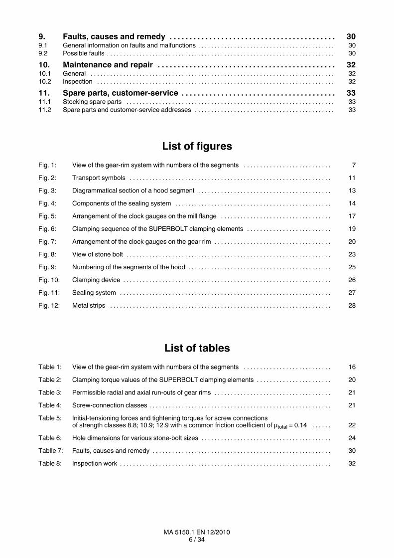
List of figures
Fig. 1: View of the gearrim system with numbers of the segments 7. . . . . . . . . . . . . . . . . . . . . . . . . . .
Fig. 2: Transport symbols 11. . . . . . . . . . . . . . . . . . . . . . . . . . . . . . . . . . . . . . . . . . . . . . . . . . . . . . . . . . . . . .
Fig. 3: Diagrammatical section of a hood segment 13. . . . . . . . . . . . . . . . . . . . . . . . . . . . . . . . . . . . . . . . .
Fig. 4: Components of the sealing system 14. . . . . . . . . . . . . . . . . . . . . . . . . . . . . . . . . . . . . . . . . . . . . . . .
Fig. 5: Arrangement of the clock gauges on the mill flange 17. . . . . . . . . . . . . . . . . . . . . . . . . . . . . . . . . .
Fig. 6: Clamping sequence of the SUPERBOLT clamping elements 19. . . . . . . . . . . . . . . . . . . . . . . . . .
Fig. 7: Arrangement of the clock gauges on the gear rim 20. . . . . . . . . . . . . . . . . . . . . . . . . . . . . . . . . . . .
Fig. 8: View of stone bolt 23. . . . . . . . . . . . . . . . . . . . . . . . . . . . . . . . . . . . . . . . . . . . . . . . . . . . . . . . . . . . . . .
Fig. 9: Numbering of the segments of the hood 25. . . . . . . . . . . . . . . . . . . . . . . . . . . . . . . . . . . . . . . . . . . .
Fig. 10: Clamping device 26. . . . . . . . . . . . . . . . . . . . . . . . . . . . . . . . . . . . . . . . . . . . . . . . . . . . . . . . . . . . . . . .
Fig. 11: Sealing system 27. . . . . . . . . . . . . . . . . . . . . . . . . . . . . . . . . . . . . . . . . . . . . . . . . . . . . . . . . . . . . . . . .
Fig. 12: Metal strips 28. . . . . . . . . . . . . . . . . . . . . . . . . . . . . . . . . . . . . . . . . . . . . . . . . . . . . . . . . . . . . . . . . . . .
List of tables
Table 1: View of the gearrim system with numbers of the segments 16. . . . . . . . . . . . . . . . . . . . . . . . . . .
Table 2: Clamping torque values of the SUPERBOLT clamping elements 20. . . . . . . . . . . . . . . . . . . . . . .
Table 3: Permissible radial and axial runouts of gear rims 21. . . . . . . . . . . . . . . . . . . . . . . . . . . . . . . . . . . .
Table 4: Screwconnection classes 21. . . . . . . . . . . . . . . . . . . . . . . . . . . . . . . . . . . . . . . . . . . . . . . . . . . . . . . .
Table 5: Initialtensioning forces and tightening torques for screw connectionsof strength classes 8.8; 10.9; 12.9 with a common friction coefficient of μtotal = 0.14 22. . . . . .
Table 6: Hole dimensions for various stonebolt sizes 24. . . . . . . . . . . . . . . . . . . . . . . . . . . . . . . . . . . . . . . .
Tablle 7: Faults, causes and remedy 30. . . . . . . . . . . . . . . . . . . . . . . . . . . . . . . . . . . . . . . . . . . . . . . . . . . . . . .
Table 8: Inspection work 32. . . . . . . . . . . . . . . . . . . . . . . . . . . . . . . . . . . . . . . . . . . . . . . . . . . . . . . . . . . . . . . . .
7 / 34MA 5150.1 EN 12/2010
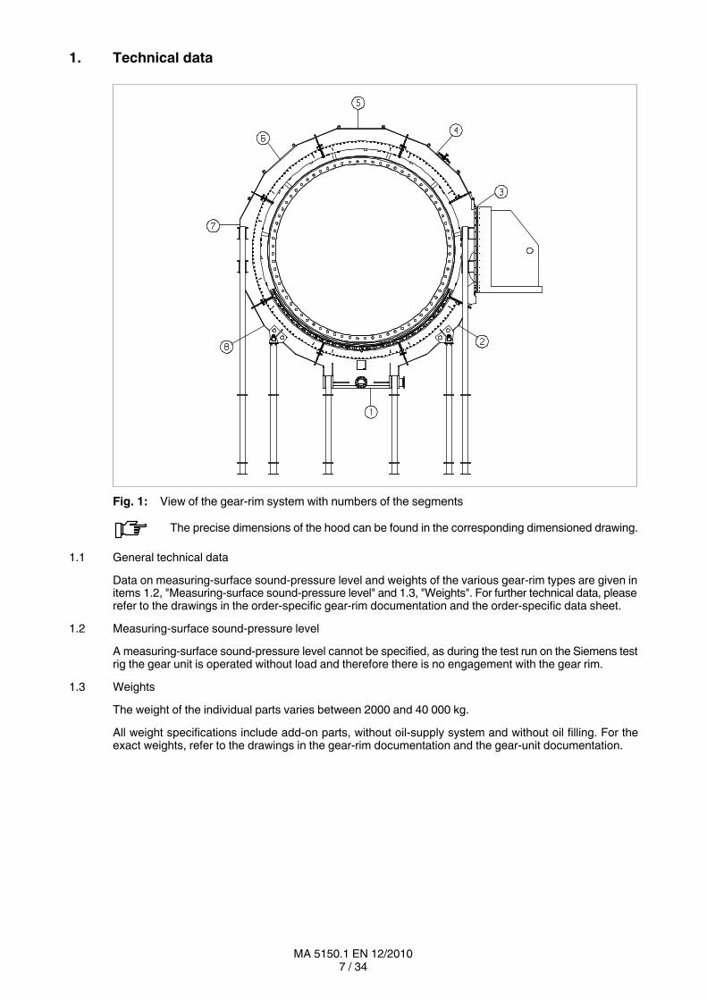
1. Technical data
Fig. 1: View of the gearrim system with numbers of the segments
The precise dimensions of the hood can be found in the corresponding dimensioned drawing.
1.1 General technical data
Data on measuringsurface soundpressure level and weights of the various gearrim types are given initems 1.2, "Measuringsurface soundpressure level" and 1.3, "Weights". For further technical data, pleaserefer to the drawings in the orderspecific gearrim documentation and the orderspecific data sheet.
1.2 Measuringsurface soundpressure level
A measuringsurface soundpressure level cannot be specified, as during the test run on the Siemens testrig the gear unit is operated without load and therefore there is no engagement with the gear rim.
1.3 Weights
The weight of the individual parts varies between 2000 and 40 000 kg.
All weight specifications include addon parts, without oilsupply system and without oil filling. For theexact weights, refer to the drawings in the gearrim documentation and the gearunit documentation.
8 / 34MA 5150.1 EN 12/2010
2. General notes
2.1 Introduction
These instructions are an integral part of the delivery of the gearrim system and must be kept in its vicinityfor reference at all times.
All persons carrying out work on the gearrim system must have read and understoodthese instructions and must adhere to them. Siemens accepts no responsibility fordamage or disruption caused by disregard of these instructions.
The "Gearrim system" described in these instructions has been designed to protect the gear rim and theoiltight guidance of the oil out of the gear unit around the gear rim. Possible areas of use for this gearrimsystem are in particular the cement and oreprocessing industries.
The gearrim system has been designed only for the area of application specified in section 1, "Technicaldata". Other operating conditions must be contractually agreed.
The gearrim system has been manufactured in accordance with the state of the art and is delivered in acondition for safe and reliable use.
The gearrim system must be used and operated strictly in accordance with the conditions laid down in thecontract governing performance and supply agreed by Siemens and the customer.
The gearrim system described in these instructions reflects the state of technical development at the timethese instructions went to print.
In the interest of technical progress we reserve the right to make changes to the individual assemblies andaccessories which we regard as necessary to preserve their essential characteristics and improve theirefficiency and safety.
2.2 Copyright
The copyright to these instructions is held by Siemens AG.
These instructions must not be wholly or partly reproduced for competitive purposes, used in anyunauthorised way or made available to third parties without our agreement.
Technical enquiries should be addressed to the following works or to one of our customer services:
Siemens AGAlfred-Flender-Straße 7746395 Bocholt
Tel.: +49 (0)2871 / 92-0Fax: +49 (0)2871 / 92-2596E-Mail: [email protected]

9 / 34MA 5150.1 EN 12/2010
3. Safety instructions
Entry to the gearrim system and its added components is not permitted duringoperation!Entry for maintenance and repair work is only permitted when the gear unit is ata standstill!Caution! Risk of falling!
Any changes on the part of the user are not permitted. This applies equally to safetyfeatures designed to prevent accidental contact.
3.1 Obligations of the user
• The operator must ensure that everyone carrying out work on the gearrim system has read andunderstood these instructions and is adhering to them in every point in order to:
─ avoid injury or damage,
─ ensure the safety and reliability of the gearrim system,
─ avoid disruptions and environmental damage through incorrect use.
• During transport, assembly, installation, dismantling, operation and maintenance of the unit, therelevant safety and environmental regulations must be complied with at all times.
• The gearrim system may only be operated, maintained and/or repaired by persons qualified for thework concerned (see "Qualified personnel" on page 3 of this manual).
• The gearrim system must not be cleaned with highpressure cleaning equipment.
• All work must be carried out with great care and with due regard to safety.
All work on the gearrim system must be carried out only when it is not in operation.The drive unit of the gearrim system must be secured against being switched onaccidentally (e.g. by locking the key switch or removing the fuses from the powersupply). A notice should be attached to the start switch stating clearly that work is inprogress on the gearrim system.
• No electrical welding work must be done at all on the gearrim system. The drives must not be used asan earthing point for welding operations. Toothed parts and bearings may be irreparably damaged bywelding.
• A potential equalisation in accordance with the applying regulations and directives must be carried out!If no threaded holes for earth connection are available on the gearrim system, other appropriatemeasures must be taken. This work must always be done by specialist electricians.
Rotating and/or movable drive components must be fitted with suitable safehoods toprevent contact.
If any inexplicable changes are noticed during operation of the gearrim system, suchas an important oil leakage or unusual noises, the drive assembly must be switchedoff immediately.
When the gearrim system is incorporated in plant or machinery, the manufacturer ofsuch plant or machinery must ensure that the contents of these instructions areincorporated in his own instructions.
• Before beginning work on pressure lines and electrical systems it must be ensured that pressure linesare not under pressure and electrical systems are disconnected from the power mains.
10 / 34MA 5150.1 EN 12/2010
• When removing the safety equipment the fixation means should be stored for later use.Removed safety equipment must be reinstalled prior to starting up.
• Notices attached to the gearrim system, such as rating plate and direction arrows, must always beobserved. They must be kept free from dirt and paint at all times. Missing plates must be replaced.
• Screws which have been damaged during assembly or disassembly work must be replaced with newones of the same strength class and type.
• Spare parts should always be obtained from Siemens (refer also to section 11).
3.2 Environmental protection
• Dispose of any packing material in accordance with regulations or separate it for recycling.
• When changing oil, the used oil must be collected in suitable containers. Any pools of oil which mayhave collected should be removed at once with an oilbinding agent.
• Preservative agents should be stored separately from used oil.
• Used oil, preservative agents, oilbinding agents and oilsoaked cloths must be disposed of inaccordance with environmental legislation.
• Disposal of the gearrim system after its useful life:
─ Drain all the operating oil, preservative agent and/or cooling agent from the gearrim system anddispose of in accordance with regulations.
─ Depending on national regulations, components of the gearrim system and/or addon parts mayhave to be disposed of in different manners or be separated for recycling.
3.3 Special dangers and personal protective equipment
• Depending on operating conditions, the surface of the gearrim system may heat up or cool down toextreme temperatures.
In case of hot surfaces (> 55 °C) there is a risk of burns!
In case of cold surfaces (< 0 °C) there is a risk of frost injury (pain, numbness,frostbite)!
During oil changes there is a risk of scalding from escaping oil!
Small foreign matter such as sand, dust, etc. can get into the cover plates of therotating parts and be thrown back by these.Risk of eye injury!
In addition to any generally prescribed personal safety equipment (such as safety shoes,safety clothing, helmet) handling the gearrim system requires wearing suitable safetygloves and suitable safety glasses!
The gearrim system does not comply with the requirements in Directive 94/9/EC andmust therefore, in the area of applicability of this directive, not be used in potentiallyexplosive areas.
Caution, serious danger!
Should the gearrim system be used outside the area of applicability ofDirective 94/9/EC within potentially explosive areas, the nationally applyingprotective prescriptions with regard to explosion protection must always beobserved.
11 / 34MA 5150.1 EN 12/2010
4. Transport and storage
Observe the instructions in section 3, "Safety instructions"!
4.1 Scope of supply
The products supplied are listed in the despatch papers. Check immediately on receipt to ensure that allthe products listed have actually been delivered. Parts damaged and/or missing parts must be reportedto Siemens in writing immediately.
If there is any visible damage, the gearrim system must not be put into operation.
4.2 Transport
When transporting our products, use only lifting and handling equipment of sufficientloadbearing capacity!Observe the notes regarding load distribution on the packing.
The gearrim system is delevered disassembled in single components. Additional items are deliveredseparately packaged, if applicable.
Different forms of packaging may be used, depending on the size of the gearrim system and the methodof transport. Unless otherwise agreed, the packaging complies with the HPE Packaging Guidelines.
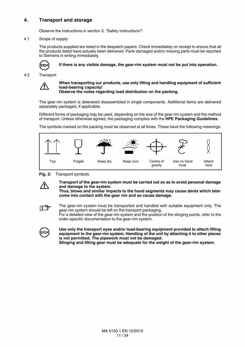
The symbols marked on the packing must be observed at all times. These have the following meanings:
Top Fragile Keep dry Keep cool Centre ofgravity
Use no handhook
Attachhere
Fig. 2: Transport symbols
Transport of the gearrim system must be carried out so as to avoid personal damageand damage to the system.Thus, blows and similar impacts to the hood segments may cause dents which latercome into contact with the gear rim and so cause damage.
The gearrim system must be transported and handled with suitable equipment only. Thegearrim system should be left on the transport packaging.For a detailed view of the gearrim system and the position of the slinging points, refer to theorderspecific documentation to the gearrim system.
Use only the transport eyes and/or loadbearing equipment provided to attach liftingequipment to the gearrim system. Handling of the unit by attaching it to other placesis not permitted. The pipework must not be damaged.Slinging and lifting gear must be adequate for the weight of the gearrim system.
12 / 34MA 5150.1 EN 12/2010
4.3 Storage of the gearrim system
The gearrim system must be stored in the position of the original packaging or in the position of use, ina sheltered place; it must be placed on a vibrationfree, dry base and covered over. If using covers, caremust be taken that no condensation forms under the cover.
When temporarily storing the gearrim system and any single components suppliedwith it, the preservative agent should be left on them. It must not be damaged,otherwise there is a risk of corrosion.
Segments or parts of the gearrim system must not be stacked one on top of the other.
If the gearrim system is being stored out of doors, it must be particularly carefullycovered, and care must be taken that neither moisture nor foreign material can collecton the system. Do avoid waterlogging (Siemens must be consulted).
Unless otherwise agreed by contract, the gearrim system must not be exposed to harmfulenvironmental factors such as corrosive chemical products, a high air pollution, high airhumidity and/or ambient temperatures outside the range of 0 to + 40 °C.Provision for special environmental conditions during transport (e.g. transport by ship) andstorage (climate, termites, etc.) must be contractually agreed.
4.4 Standard coating and preservation
The gearrim system is preserved with a protective agent.
The characteristics of the protective preservation depend on the ambient conditions stipulated in the orderrelating to method of transport, storage and area of application.
The gearrim system is normally delivered completely ready, with a priming anda finish coat.
Where gearrim systems are delivered with a priming coat only, it is necessary to applya finishing coat in accordance with directives applying to the specific application. Thepriming coat alone is not suitable to provide a sufficient longterm corrosionprotection.
Ensure that the coat is not damaged!
Any damage may cause failure of the external protective coating and corrosion.
Unless otherwise contractually agreed, the exterior preservation is guaranteed for 24 months,provided that storage is in dry, frostfree sheds.
The guarantee period starts on the date of delivery or that of the notice that the item is readyfor shipment.
The exterior protection should be checked in case of protracted intermediate storage.
13 / 34MA 5150.1 EN 12/2010
5. Technical description
Observe the instructions in section 3, "Safety instructions"!
5.1 General description
The gearrim system completes a tubular mill, which is operated with a type "DMG2" gear unit.
The following contains the technical descriptions of the individual elements of the gearrim system. Thesystem is made up of three individual systems:
─ the gear rim
─ the hood
─ the sealing system
Operation and maintenance must be in accordance with all operating instructionssupplied. For technical data, refer to the orderspecific documents.
5.2 Gear rim
The gear rim is fastened to the tubular mill by means of a flanged connection. Through this the type DMG2gear unit drives the tubular mill. On the gear rim are the sealing surfaces for the sealing system fitted to thehood.
Fitting of the gear rim is described in item 6.3, "Fitting the gear rim".
5.3 Hood
The hood shown here is an integral part of a tubularmill drive. It is intended for use on a type DMG2FLENDER gear unit and must perform the following functions:
• Protect against unintentional contact with the rotating gear rim.
• Ensure the oiltightness and the accurate drainage of the oil in the compressedoil lubricated gear unitand that of the gear rim.The oil is fed back into the oilsupply system.
• Sealing of the total system by the seals applied.
The hood is placed on feet and connected to the gear unit by an elastic seal.
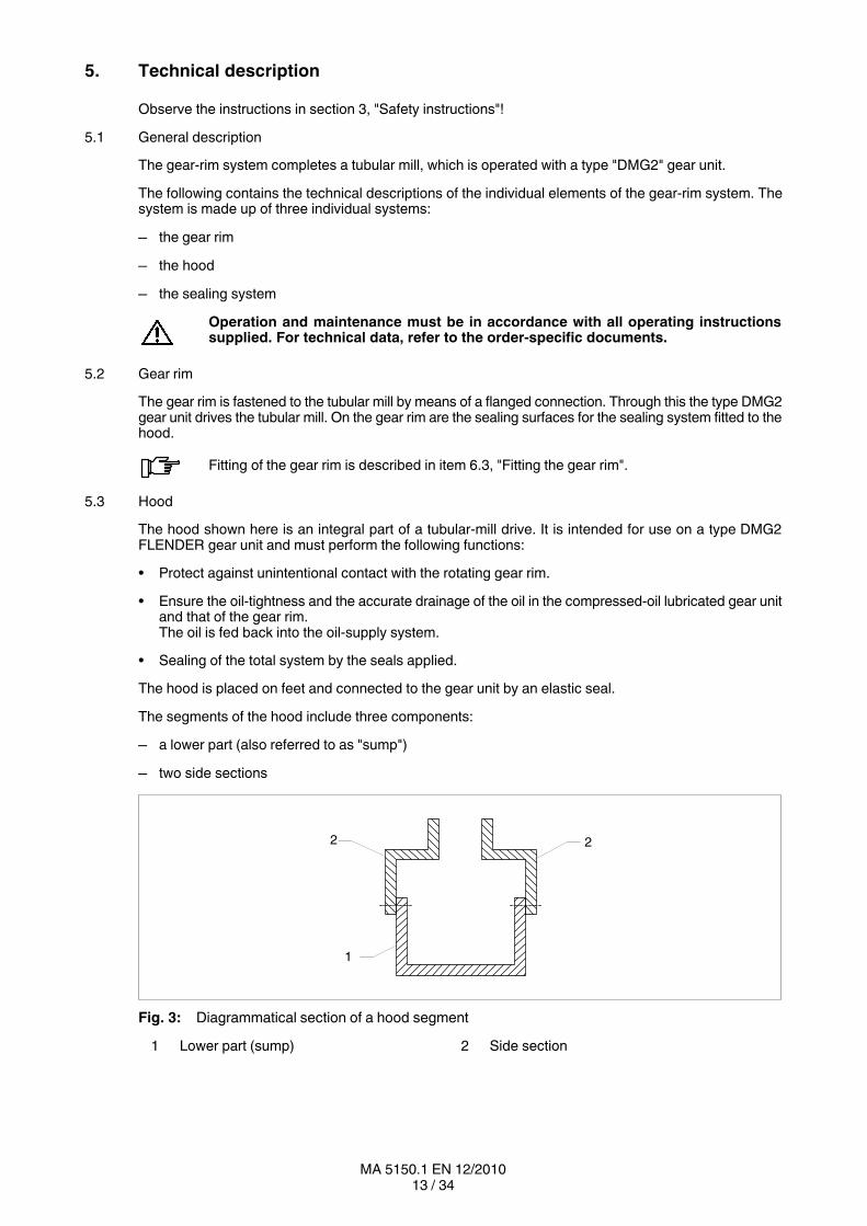
The segments of the hood include three components:
─ a lower part (also referred to as "sump")
─ two side sections
2 2
1
Fig. 3: Diagrammatical section of a hood segment
1 Lower part (sump) 2 Side section
14 / 34MA 5150.1 EN 12/2010
A sealing paste is to be used to seal the space between the segments.
The fitting of the hood is described in item 6.5, "Fitting the protective cover".
5.4 Sealing system
The sealing system includes three elements:
─ Centrifugal ring
─ Doublelip seal
─ Dust protection
The fitting of the sealing system is described in item 6.6, "Fitting the sealing system".
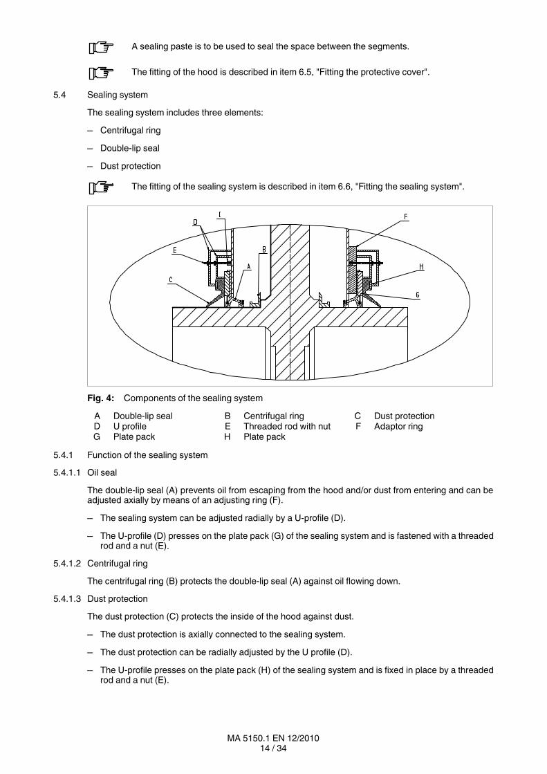
Fig. 4: Components of the sealing system
A Doublelip seal B Centrifugal ring C Dust protectionD U profile E Threaded rod with nut F Adaptor ringG Plate pack H Plate pack
5.4.1 Function of the sealing system
5.4.1.1 Oil seal
The doublelip seal (A) prevents oil from escaping from the hood and/or dust from entering and can beadjusted axially by means of an adjusting ring (F).
─ The sealing system can be adjusted radially by a Uprofile (D).
─ The Uprofile (D) presses on the plate pack (G) of the sealing system and is fastened with a threadedrod and a nut (E).
5.4.1.2 Centrifugal ring
The centrifugal ring (B) protects the doublelip seal (A) against oil flowing down.
5.4.1.3 Dust protection
The dust protection (C) protects the inside of the hood against dust.
─ The dust protection is axially connected to the sealing system.
─ The dust protection can be radially adjusted by the U profile (D).
─ The Uprofile presses on the plate pack (H) of the sealing system and is fixed in place by a threadedrod and a nut (E).
15 / 34MA 5150.1 EN 12/2010
6. Fitting
Observe the instructions in section 3, "Safety instructions"!
6.1 General information on fitting
When transporting the hood system observe the notes in section 4, "Transport and storage".
The hood system must be slung by the points marked (see section 4, "Transport andstorage").
Fitting work must be done with great care by authorised, trained and qualified personnel. The manufacturercannot be held liable for damage caused by incorrect assembly and installation.
During the planning phase sufficient space must be left around the hood for later care and maintenancework.
Adequate lifting equipment must be available before beginning the fitting work.
During operation the unit must not be allowed to heat up through exposure to heatfrom external sources such as sunlight, and suitable measures must be taken toprevent this!Do avoid a heat concentration!
The operator should ensure that no foreign bodies affect the proper function of thehood system (e.g. falling objects or heaping over).
No welding work at all must be done on the hood system.The hood system must not be used as an earthing point for welding operations.Toothed parts and bearings may be irreparably damaged by welding.
For fastening down, the information given in the dimensioned drawing, foundationand installation plan and in the installation instructions for the gearrim system mustbe observed.
The drawings are included in the documentation to the gearrim system.
All the fastening points provided by the design of the unit must be used.Screws which have been damaged during assembly or disassembly work must be replacedwith new ones of the same strength class and type.
To ensure proper lubrication during operation, the mounting position specified on the drawingsmust always be observed.
16 / 34MA 5150.1 EN 12/2010
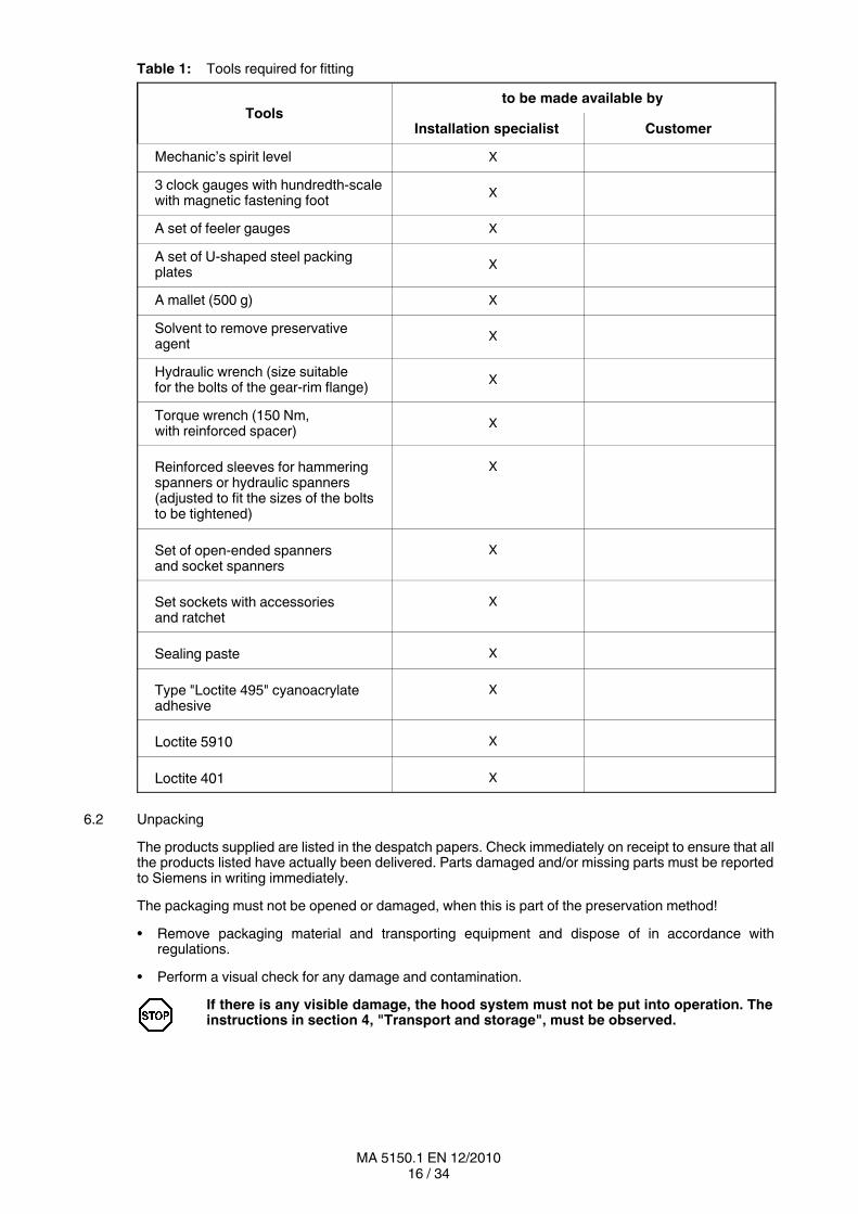
Table 1: Tools required for fitting
Toolsto be made available by
Installation specialist Customer
Mechanic’s spirit level X
3 clock gauges with hundredthscalewith magnetic fastening foot
X
A set of feeler gauges X
A set of Ushaped steel packingplates
X
A mallet (500 g) X
Solvent to remove preservativeagent
X
Hydraulic wrench (size suitablefor the bolts of the gearrim flange)
X
Torque wrench (150 Nm,with reinforced spacer)
X
Reinforced sleeves for hammeringspanners or hydraulic spanners(adjusted to fit the sizes of the boltsto be tightened)
X
Set of openended spannersand socket spanners
X
Set sockets with accessoriesand ratchet
X
Sealing paste X
Type "Loctite 495" cyanoacrylateadhesive
X
Loctite 5910 X
Loctite 401 X
6.2 Unpacking
The products supplied are listed in the despatch papers. Check immediately on receipt to ensure that allthe products listed have actually been delivered. Parts damaged and/or missing parts must be reportedto Siemens in writing immediately.
The packaging must not be opened or damaged, when this is part of the preservation method!
• Remove packaging material and transporting equipment and dispose of in accordance withregulations.
• Perform a visual check for any damage and contamination.
If there is any visible damage, the hood system must not be put into operation. Theinstructions in section 4, "Transport and storage", must be observed.
17 / 34MA 5150.1 EN 12/2010
6.3 Fitting the twopart gear rim
The required work material must be placed ready in preparation for fitting the gear rim (see material list inthe documentation to the gearrim system).
Note correct mating of the two gearrim halves.For this the marks made at the respective joining points to clearly indicate positionsmust be noted.
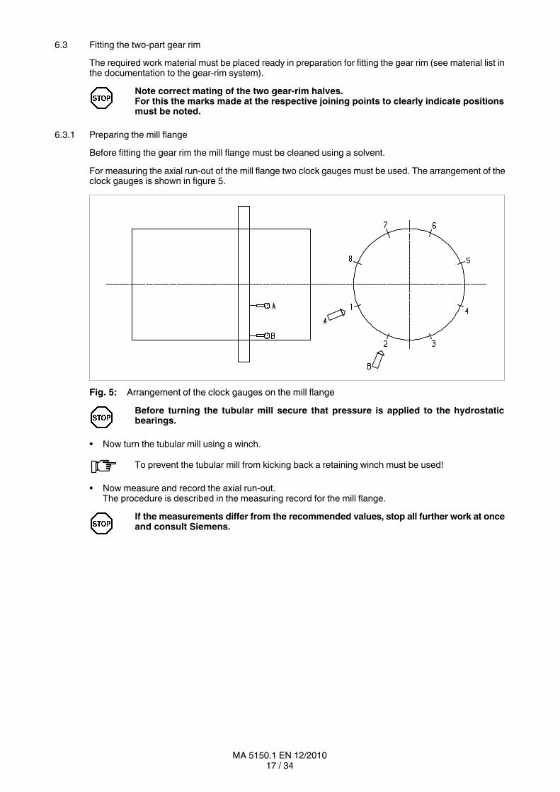
6.3.1 Preparing the mill flange
Before fitting the gear rim the mill flange must be cleaned using a solvent.
For measuring the axial runout of the mill flange two clock gauges must be used. The arrangement of theclock gauges is shown in figure 5.
Fig. 5: Arrangement of the clock gauges on the mill flange
Before turning the tubular mill secure that pressure is applied to the hydrostaticbearings.
• Now turn the tubular mill using a winch.
To prevent the tubular mill from kicking back a retaining winch must be used!
• Now measure and record the axial runout.The procedure is described in the measuring record for the mill flange.
If the measurements differ from the recommended values, stop all further work at onceand consult Siemens.
18 / 34MA 5150.1 EN 12/2010
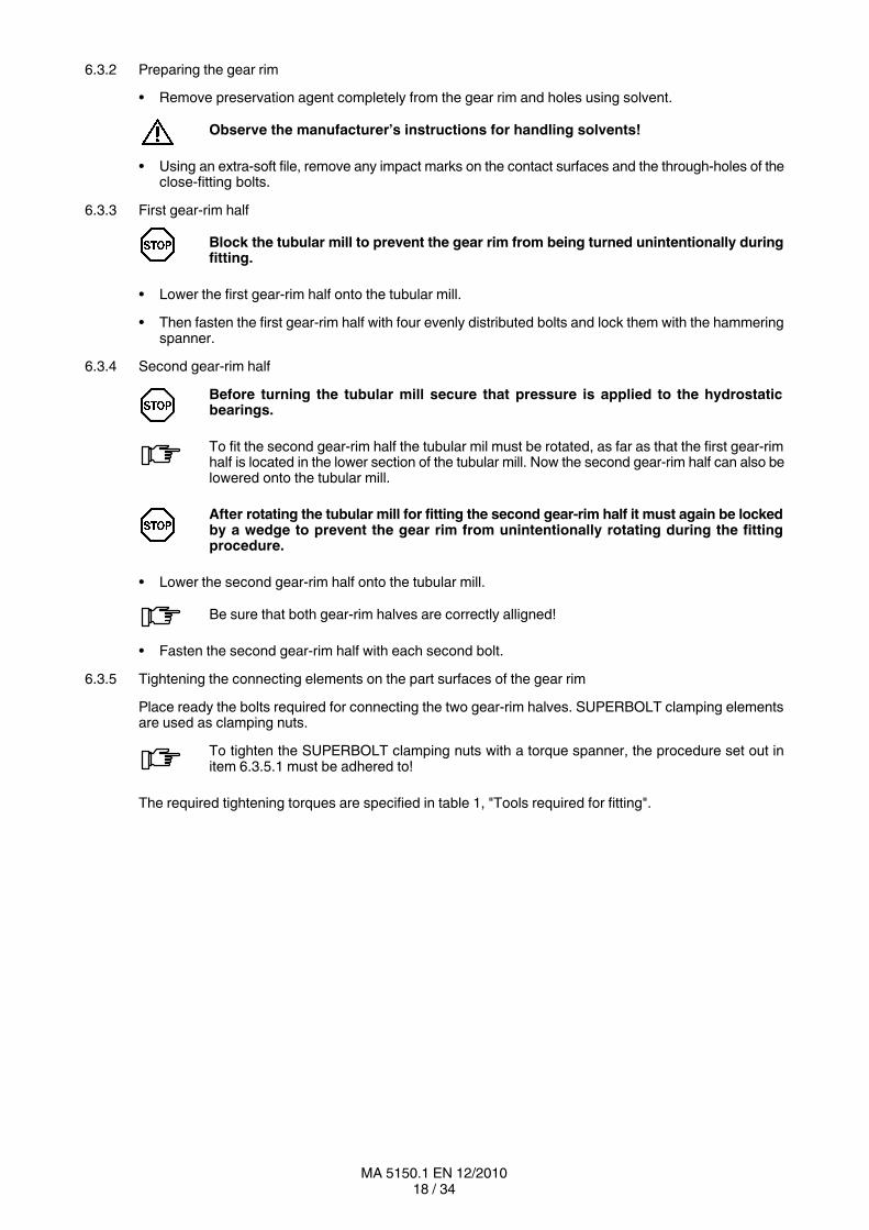
6.3.2 Preparing the gear rim
• Remove preservation agent completely from the gear rim and holes using solvent.
Observe the manufacturer’s instructions for handling solvents!
• Using an extrasoft file, remove any impact marks on the contact surfaces and the throughholes of theclosefitting bolts.
6.3.3 First gearrim half
Block the tubular mill to prevent the gear rim from being turned unintentionally duringfitting.
• Lower the first gearrim half onto the tubular mill.
• Then fasten the first gearrim half with four evenly distributed bolts and lock them with the hammeringspanner.
6.3.4 Second gearrim half
Before turning the tubular mill secure that pressure is applied to the hydrostaticbearings.
To fit the second gearrim half the tubular mil must be rotated, as far as that the first gearrimhalf is located in the lower section of the tubular mill. Now the second gearrim half can also belowered onto the tubular mill.
After rotating the tubular mill for fitting the second gearrim half it must again be lockedby a wedge to prevent the gear rim from unintentionally rotating during the fittingprocedure.
• Lower the second gearrim half onto the tubular mill.
Be sure that both gearrim halves are correctly alligned!
• Fasten the second gearrim half with each second bolt.
6.3.5 Tightening the connecting elements on the part surfaces of the gear rim
Place ready the bolts required for connecting the two gearrim halves. SUPERBOLT clamping elementsare used as clamping nuts.
To tighten the SUPERBOLT clamping nuts with a torque spanner, the procedure set out initem 6.3.5.1 must be adhered to!
The required tightening torques are specified in table 1, "Tools required for fitting".

19 / 34MA 5150.1 EN 12/2010
6.3.5.1 Procedure of tightening the SUPERBOLT clamping elements
Preparatory work:
• Thoroughly clean the threads and contact surfaces.
• Make sure that the pressure bolts do not project and that they are well greased.
• If required, lubricate the screw thread of the pressure bolts with special graphite grease (not containingmolybdenum sulphide).
• Screw the nut up by hand until the support washers lock.
• Then undo the nut about half a turn and leave about 1 to 3 mm play between the support washer andthe nut body of the SUPERBOLT.
Tightening:
Step 1: Tighten four pressure screws (see 1 to 4 in figure 6) crosswise by hand so as to centrethe
main screw thread and eliminate any play.
Step 2: The screws tightened in step 1 must now be tightened crosswise at 50 % of theprescribed
torque (see table 2, "Clamping torque values of the SUPERBOLT clamping elements").
Step 3: The screws tightened in step 2 must now be tightened diagonally at 100 % of theprescribed clamping torque.
Step 4: Then tighten all pressure bolts in clockwise direction to 100 % of the recommendedclamping toruqe.
It may be required to repeat step 4 must several times until the pressure bolts are evenlytightened (less than 20° remaining angular backlash). Normally 2 to 3 turns suffice for this, inthe case of long screws correspondingly more.
“A” “B”
Fig. 6: Clamping sequence of the SUPERBOLT clamping elements
A Tightening sequence for steps 1, 2 and 3 B Tightening sequence for step 4
20 / 34MA 5150.1 EN 12/2010
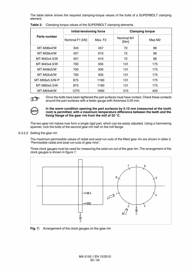
The table below shows the required clampingtorque values of the bolts of a SUPERBOLT clampingelement.
Table 2: Clamping torque values of the SUPERBOLT clamping elements
Parts number
Initialtensioning force Clamping torque
Nominal F1 [kN] Max. F2Nominal M1
[Nm]Max M2
MT-M36x4/W 343 457 72 96
MT-M39x4/W 457 610 72 96
MT-M42x4.5/W 457 610 72 96
MT-M45x4.5/W 700 935 131 175
MT-M48x5/W 700 935 131 175
MT-M52x5/W 700 935 131 175
MT-M56x5.5/W-P 875 1160 131 175
MT-M60x5.5/W 875 1160 131 175
MT-M64x6/W 1270 1690 315 420
Once the bolts have been tightened the part surfaces must have contact. Check these contactsaround the part surfaces with a feeler gauge with thickness 0.05 mm.
In the warm condition opening the part surfaces by 0.10 mm (measured at the toothroot) is permitted, with a maximum temperature difference between the teeth and thefixing flange of the gear rim from the mill of 20 °C.
The two gearrim halves now form a single rigid part, which can be easily adjusted. Using a hammeringspanner, lock the bolts of the second gearrim half on the mill flange.
6.3.5.2 Setting the gear rim
The maximum permissible values of radial and axial runouts of the fitted gear rim are shown in table 3,"Permissible radial and axial runouts of gear rims".
Three clock gauges must be used for measuring the axial runout of the gear rim. The arrangement of theclock gauges is shown in figure 7.
Fig. 7: Arrangement of the clock gauges on the gear rim

21 / 34MA 5150.1 EN 12/2010
Before turning the tubular mill secure that pressure is applied to the hydrostaticbearings.
• Now turn the tubular mill using a winch.
To prevent the tubular mill from kicking back a retaining winch must be used!
The radial and axial runout of the gear rim must not exceed the values specified intable 3, "Permissible radial and axial runouts of gear rims". If the values are exceededthe gear rim must be adjusted again!
• Now the radial and axial runout must be measured and the result recorded.The procedure is described in the measurement record for the gear rim.
Only the final condition must be recorded (after tightening all bolts).
Table 3: Permissible radial and axial runouts of gear rims
Tipcircle diameter of the gear rim[m]
Permissible radial runout[mm]
Permissible axial runout[mm]
≤ 5.0 0.8 0.8
> 5.0 1.0 1.0
A deviation exceeding 0.2 mm from one point to the next (e.g. between points 4 and 5)is not permitted.
To adjust the gear rim, Ushaped metal plates must be placed around the bolts at the places to be adjustedbetween the gearrim flange and the mill flange. Enough filling plates must be fitted until it is shown byremeasurement that the permitted radial and axial runout values have been achieved.
By means of the torque wrench finally tighten the bolts for attaching the gear rim to the mill flange in thefollowing order:
• every 8th bolt,
• every 4th bolt,
• then all remaining bolts.
Finally the radial and axial runouts of the gear rim must be measured and recorded in the measurementrecord.
Table 4: Screwconnection classes
Screwconnectionclass
Distributionof emitted torque
on the tool
Tightening procedure(Usually the tightening processes lie within the stated
tool distribution)
C ± 5 % up to ± 10 %
‐ hydraulic tightening with mechanical screwdriver torquecontrolled tightening with torque wrench
or signalemitting torque wrench tightening with precision mechanical screwdriver
with dynamic torque measuring
D ± 10 % up to ± 20 % ‐ torquecontrolled tightening with mechanical screwdriver
E ± 20 % up to ± 50 %
‐ tightening with pulse screwdriver or impact wrenchwithout adjustment checking device
tightening by hand, using a spanner without torquemeasuring device

22 / 34MA 5150.1 EN 12/2010
6.3.6 Tightening torques and initialtensioning forces
The tightening torques apply to friction coefficients of μtotal = 0.14. The frictioncoefficient μtotal = 0.14 applies here to lightly oiled steel bolts, blackannealed or phosphatisedand dry, cut mating threads in steel or cast iron. Lubricants which alter the friction coefficientmust not be used and may overload the screw connection.
Table 5: Initialtensioning forces and tightening torques for screw connections of strength classes8.8; 10.9; 12.9 with a common friction coefficient of μtotal = 0.14
Nominalthread
diameter
d
Strengthclass ofthe bolt
Initialtensioning forcefor screwconnection classes
from table 4
Tightening torquefor screwconnection classes
from table 4
Surface pressure under
the bolt head
C D E C D EHexagon
head bolt
DIN 931
Cheese
head bolt
DIN 912
mm FM min. in N MA in Nm pact. in N/mm2
M12
8.8 20600 13200 8200 87,1 75,0 66,9 348 366
10.9 30300 19400 12100 128 110 98,5 512 538
12.9 35400 22600 14200 150 129 115 598 629
M36
8.8 194000 142000 78000 2420 2170 1860 362 319
10.9 276000 177000 111000 3450 2970 2660 516 454
12.9 323000 207000 129000 4040 3480 3100 604 531
M42
8.8 261000 167000 105000 3810 3280 2930 323 306
10.9 372000 238000 149000 5420 4670 4180 460 436
12.9 435000 278000 174000 6340 5460 4880 538 510
M48
8.8 332000 212000 133000 5540 4770 4260 320 301
10.9 473000 303000 189000 7890 6800 6070 456 430
12.9 554000 354000 222000 9240 7960 7100 534 503
M56
8.8 449000 287000 180000 8710 7500 6700 389 313
10.9 638000 408000 255000 12400 10700 9520 553 444
12.9 750000 480000 300000 14600 12500 11200 650 523
M64
8.8 588000 376000 235000 13000 11200 9960 416 300
10.9 838000 536000 335000 18500 15900 14200 593 428
12.9 975000 624000 390000 21500 18500 16500 690 498
The tightening torque determined by the nominal diameter and the quality of the bolts used(for example, 2080 Nm for an M36 bolt in class 8.8) must be adhered to; see table 5, "Initialtensioning forces and tightening torques for screw connections".
Check correct seating of all the bolts.
Check radial and axial runouts of the fitted gear rims another time. If the values obtainedexceed the tolerances, the setting procedures must be repeated. Otherwise the values arerecorded in the measurement record.
23 / 34MA 5150.1 EN 12/2010
6.4 Fitting and setting the type "DMG2" gear unit
Once the gear rim has been fitted the gear unit must be fitted and set. Fitting and setting the gear unit mustonly be done by qualified personnel properly trained by Siemens AG.
Prior to putting the mill in operation the hood with its sealing system must have beenfitted (see items 6.5, "Fitting the protective cover" and 6.6, "Fitting the sealingsystem") and the lubrication system of the gearrim gear unit have been checked.
6.5 Mounting the hood
Before the hood can be fitted, the centrifugal ring must be fitted onto the sealing surface around the gearrim (see item 6.6.1, "Fitting the centrifugal ring").
6.5.1 Checking the dimensions before fitting the hood
The precise dimensions of the hood can be found in the corresponding dimensioned drawingin the orderspecific documentation.
The following dimensions must be checked:
• The vertical distance between the foot plates on the floor and the horizontal mill axis.
• The foot dimensions between the differently shaped foot plates on the foundation.
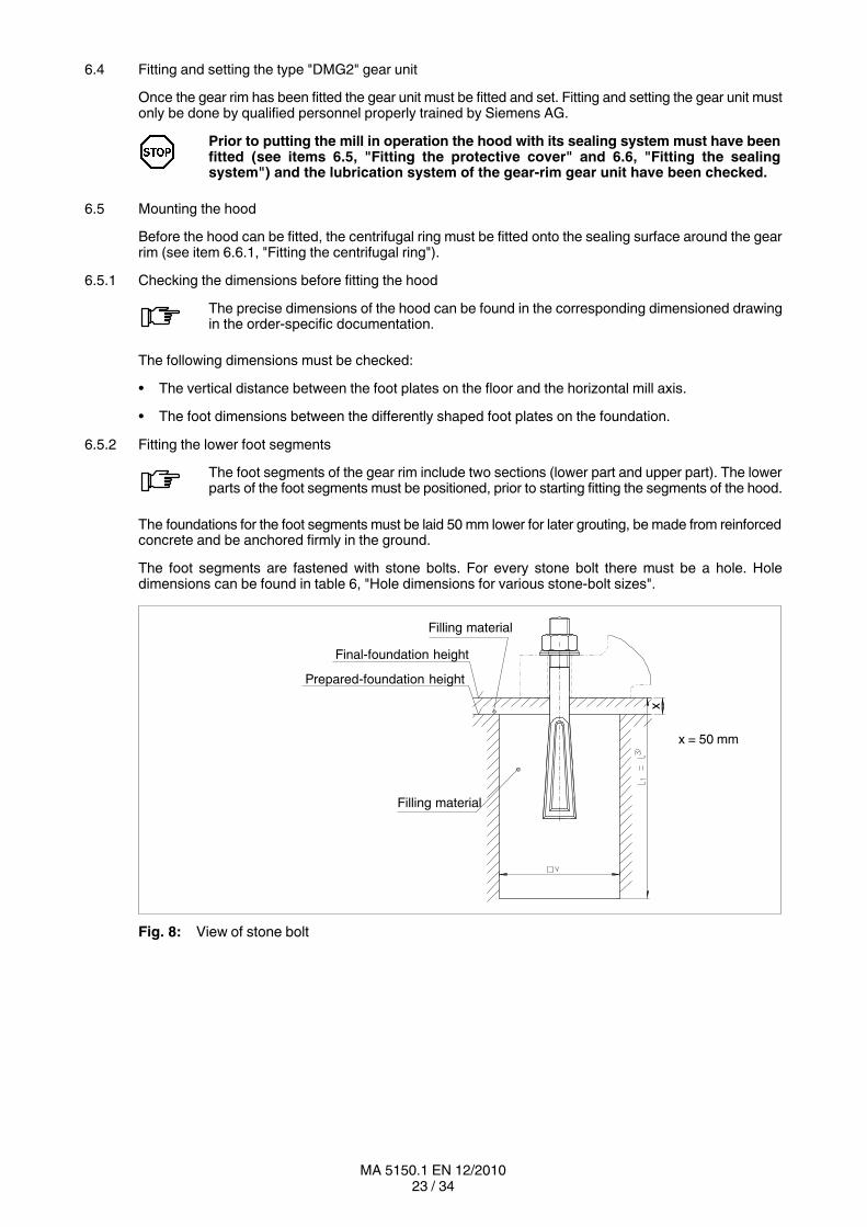
6.5.2 Fitting the lower foot segments
The foot segments of the gear rim include two sections (lower part and upper part). The lowerparts of the foot segments must be positioned, prior to starting fitting the segments of the hood.
The foundations for the foot segments must be laid 50 mm lower for later grouting, be made from reinforcedconcrete and be anchored firmly in the ground.
The foot segments are fastened with stone bolts. For every stone bolt there must be a hole. Holedimensions can be found in table 6, "Hole dimensions for various stonebolt sizes".
Filling material
Finalfoundation height
Preparedfoundation height
Filling material
x
x = 50 mm
Fig. 8: View of stone bolt

24 / 34MA 5150.1 EN 12/2010
Table 6: Hole dimensions for various stonebolt sizes
Stone boltsd x l
Fitting dimensions/hole dimensions
v x v x l1
Stone boltsd x l
Fitting dimensions/hole dimensions
v x v x l1
M8 x 125 35 x 35 x 125 M20 x 250 60 x 60 250
M10 x 160 40 x 40 x 160 M20 x 400 60 x 60 x 400
M12 x 200 40 x 40 x 200 M24 x 500 70 x 70 x 500
M16 x 250 50 x 50 x 250 M30 x 500 90 x 90 x 500
M16 x 400 50 x 50 x 400 M30 x 630 90 x 90 x 630
Procedure:
• Place the lower part of the foot segment on the floor.
• Insert the stone bolt through the hole in the foot.
• Screw the nut on by hand until about halfway along the stone bolt thread.
• Grout fitting hole together with stone bolt.
• Repeat this procedure for each stone bolt.
Fit and align the hood as described in item 6.5.3!
• After fitting and aligning the hood fill up the remaining 50 mm of the foundation.
The filling material for the prepared foundation must be completely set before the remaining50 mm are grouted!

25 / 34MA 5150.1 EN 12/2010
6.5.3 Fitting the hood segments
The hood must be fitted from below upwards (see step 1 to step 5). The numbering of the segments of thehood can be found in table 9, "Numbering of the segments of the protective cover".
The hood segments must be fitted in exactly the same order as in the trial construction.The segments have been marked to show clearly their fitting positions. These markedcomponent parts must be fitted as stated on the drawing (see figure 9 "Numbering ofthe segments of the hood").
a
b
Fig. 9: Numbering of the segments of the hood
a Lower section of the foot segment b Upper section of the foot segment
Step 1: Screw the bottom three sump segments (segment 1, 2 and 3) together on the floor andthen, using a fork stacker, place them as a unit on the bottom foot segments.
When transporting our products, use only lifting and handling equipment of sufficientloadbearing capacity!Observe the notes regarding load distribution on the packing.
Step 2: Screw the side section onto the sump segments which have been fitted in step 1(segments 1, 2 and 8). Thus is formed the substructure of the hood.
Step 3: Fit the twopiece segment 3. Segment 3 will later serve to connect the gear unit.Using a crane, place the two sump parts around the gear rim from the side and fit themto the bottom sump segments and the foot segments provided for this. Prefasten all thesegments to the flange faces with positioning pins and then tighten.
26 / 34MA 5150.1 EN 12/2010
Step 4: Fit segment 7.The sump must first be placed on its intended foot, fastened to the flange face ofsegment 8 with positioning pins and then screwed up tight. Then fit the two sidesegments.
Step 5: Screw the three top sump segments (segment 4, 5 and 6) together on the floor and then,using a crane, place them as a unit on the flange face of hood segments number 3 and7 from above. Fasten the segments with positioning pins and then screw up tight.Next, fit the intended side parts to the sump segments.Finally fit the seal between the gear unit and the hood (see item 6.6, "Fitting the sealingsystem").
All the elements must be aligned with one another with positioning pins.
To adjust the height of the feet, the foot plates can be adjusted with the aid of the stone bolts.It is further possible to insert spacing plates between the two foot segments.
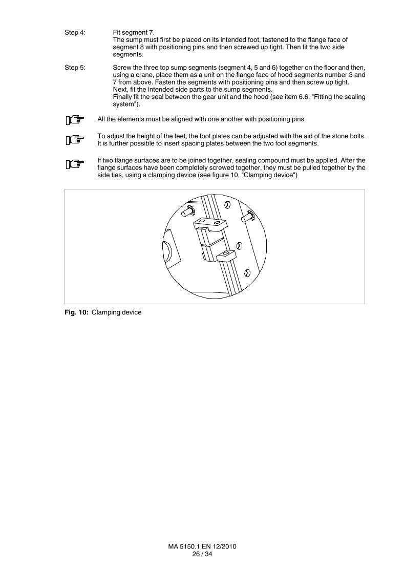
If two flange surfaces are to be joined together, sealing compound must be applied. After theflange surfaces have been completely screwed together, they must be pulled together by theside ties, using a clamping device (see figure 10, "Clamping device")
Fig. 10: Clamping device

27 / 34MA 5150.1 EN 12/2010
6.6 Fitting the sealing system
Fig. 11: Sealing system
A Doublelip seal B Centrifugal ring C Dust protectionD U profile E Threaded rod with nut F Adaptor ringG Plate pack H Plate pack
6.6.1 Fitting the centrifugal ring
When the gear rim has been completely fitted, the centrifugal ring (B) must be fitted.
The centrifugal ring must be cut open in one place for easier fitting.
• Push the centrifugal ring onto the sealing surface of the gear rim as far as the stop.
• Pull tight at the parting point and bond together with Loctite 2701.
6.6.2 Fitting the oil seal and the dust protection
• When the hood has been completely fitted, screw the threaded rods into the nuts provided for this onthe wall of the protective hood.
• Place the doublelip seal (A) with inserted springs around the sealing surface and onto the wall of thehood.
• Fit a plate pack (G) into the Ushaped notch on the neck of the doublelip seal.
• Now initially fasten by placing the small Uprofile (D) through the threaded rod (E) and fasten it witha nut.
• Now align the doublelip seal with the sealing surface.
Repeat this procedure until the oil seal is aligned all the way round.
• Place the dust cover (C) on the plate pack (G) of the doublelip seal (A) and fasten it with the largerUprofile (D).
• Finally, cut the dust cover open about 300 mm in the centre to allow impurities inside to escape.

28 / 34MA 5150.1 EN 12/2010
6.6.3 Fitting the outer hood plates
Seven identically constructed hood plates must be fitted per side in the upper part of the hood(at positions 8 o’clock to 4 o’clock).
• Fit the hood plates at the places provided for them and screw up tight.
6.6.4 Fitting the seal between the hood and the gear unit
• Lay the sealing band around the two sealing faces of the gear unit and hood segment 3.
Take care that the holes in the sealing band are aligned with those in the two sealing surfaces.Also take care that the sealing flap overlaps itself completely in two layers on the upper side.
• Next, lay the metal strips (see figure 12) on the sealing band and screw together.
To adjust the gear rim, Ushaped metal plates must be placed around the bolts at the places to be adjustedbetween the gearrim flange and the mill flange. Enough filling plates must be fitted until it is shown byremeasurement that the permitted radial and axial runout values have been achieved.
“A”
“A”
1
Fig. 12: Metal strips
1 Metal strips
29 / 34MA 5150.1 EN 12/2010
7. Startup
Observe the instructions in section 3, "Safety instructions"!
The gear rim must not be started up, if the required instructions are not available.
A precondition of the warranty is initial startup by Siemens specialists or suitably trained specialistsauthorised by Siemens. Siemens urgently recommend initially driving the tubular mill via the main drivelikewise under the supervision of the abovementioned specialists.
Any setting of the drive in motion represents a startup!
For this reason the gearunit instructions must be adhered to, particularly if maintenance work is carriedout on the tubular mill during which this is rotated and the gear unit along with it.
Additional instructions regarding startup can be found in the gearunit documentation.
8. Operation
Observe the instructions in section 3, "Safety instructions", in section 9, "Faults, causes and remedy", andin section 10, "Maintenance and repair"!
To achieve a satisfactory and troublefree operation of the equipment, be certain to observe the workingvalues specified in section 1, "Technical Data" of the gearunit documentation, as well as the informationgiven in the operating instructions of the oilsupply system and the gear unit.
During operation the gearrim system must be monitored for:
• Operating temperature An oilsupply temperature with the following values should aimed for:40 °C up to 45 °C.The maximum permissible oilsupply temperature is:55 °C (applies to mineral oil)60 °C (applies to synthetic oil)At higher temperatures the gearrim system must be shut down andSiemens should be consulted.
The lubricating oil in the lubrication circuit must be filtered during operation (nominal filterfineness 25 μm).
8.1 Irregularities
If any irregularities are noticed during operation, the drive assembly must be switchedoff at once.
Determine the cause of the fault, using table 7, "Faults, causes and remedy"(see item 9.2).
Table 7, "Faults, causes and remedy", contains a list of possible faults, their causesand suggested remedies.
If the cause cannot be found, a specialist from one of our customerservice centresshould be called in (see section 2, "General notes").
30 / 34MA 5150.1 EN 12/2010
9. Faults, causes and remedy
Observe the instructions in section 3, "Safety instructions", and in section 10, "Maintenance and repair"!Observe also the section "Faults, causes and remedy" in the documentation to the gearunit and that tothe oilsupply system.
9.1 General information on faults and malfunctions
Faults and malfunctions occurring during the guarantee period and requiring repair work on thegearrim system must be carried out only by Siemens specialists.For the case of faults and malfunctions occurring after the guarantee period and whose causecannot be precisely identified or whose remedy requires intervention on the gearrim system,we advise our customers to call in our Siemens specialists.
Siemens will not be bound by the terms of the guarantee or otherwise be responsiblefor proper function iof the gearrim system in cases of improper use of the gearrimsystem, modifications to the gearrim system carried out without the agreement ofSiemens or use of spare parts not supplied by Siemens.
To remedy faults and malfunctions, the gearrim system must always be taken out ofservice.Secure the drive assembly to prevent it from being started up accidentally.Attach a warning notice to the start switch.
9.2 Possible faults
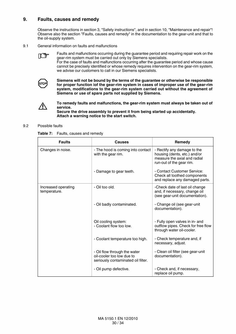
Table 7: Faults, causes and remedy
Faults Causes Remedy
Changes in noise. - The hood is coming into contactwith the gear rim.
- Damage to gear teeth.
- Rectify any damage to thehousing (dents, etc.) and/ormeasure the axial and radialrunout of the gear rim.
- Contact Customer Service:Check all toothed componentsand replace any damaged parts.
Increased operatingtemperature.
- Oil too old.
- Oil badly contaminated.
Oil cooling system:‐ Coolant flow too low.
- Coolant temperature too high.
- Oil flow through the wateroilcooler too low due toseriously contaminated oil filter.
- Oil pump defective.
-Check date of last oil changeand, if necessary, change oil(see gearunit documentation).
- Change oil (see gearunitdocumentation).
- Fully open valves in in andoutflow pipes. Check for free flowthrough water oilcooler.
- Check temperature and, ifnecessary, adjust.
- Clean oil filter (see gearunitdocumentation).
- Check and, if necessary,replace oil pump.
31 / 34MA 5150.1 EN 12/2010
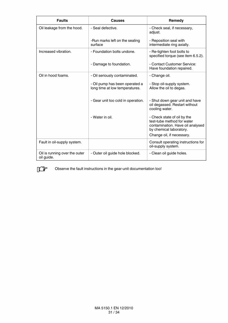
Faults RemedyCauses
Oil leakage from the hood. - Seal defective.
-Run marks left on the sealingsurface
- Check seal, if necessary,adjust.
- Reposition seal withintermediate ring axially.
Increased vibration. - Foundation bolts undone.
- Damage to foundation.
- Retighten foot bolts tospecified torque (see item 6.5.2).
- Contact Customer Service:Have foundation repaired.
Oil in hood foams. - Oil seriously contaminated.
- Oil pump has been operated along time at low temperatures.
- Gear unit too cold in operation.
- Water in oil.
- Change oil.
- Stop oilsupply system.Allow the oil to degas.
- Shut down gear unit and haveoil degassed. Restart withoutcooling water.
- Check state of oil by thetesttube method for watercontamination. Have oil analysedby chemical laboratory.
Change oil, if necessary.
Fault in oilsupply system. Consult operating instructions foroilsupply system.
Oil is running over the outeroil guide.
- Outer oil guide hole blocked. - Clean oil guide holes.
Observe the fault instructions in the gearunit documentation too!
32 / 34MA 5150.1 EN 12/2010
10. Maintenance and repair
Observe the instructions in section 3, "Safety instructions", and in section 9, "Faults, causes and remedy"!
10.1 General
Maintenance comprises all measures for preserving and restoring the required condition and forascertaining and assessing the actual condition of the technical means of a system.
In this sense maintenance is a comprehensive generic concept which can be subdivided into three areas:inspection; maintenance, including lubrication; and repair.
Before starting any maintenance work, repairs or other work on the gearrim system,the operator of the system must ensure that the drive motors (main and auxiliary drivemotor) are secured against unintentional starting.The tubular mill must be swung out and secured with the holding brake!
The gearrim system must be protected against falling objects.
Protective devices for rotating parts must be checked for correct seating. Contact withrotating parts is not permitted.
For operation and maintenance the technical data, lists of equipment and drawingsprepared specifically under the order and appended to the operating instructionsmust be taken into consideration.
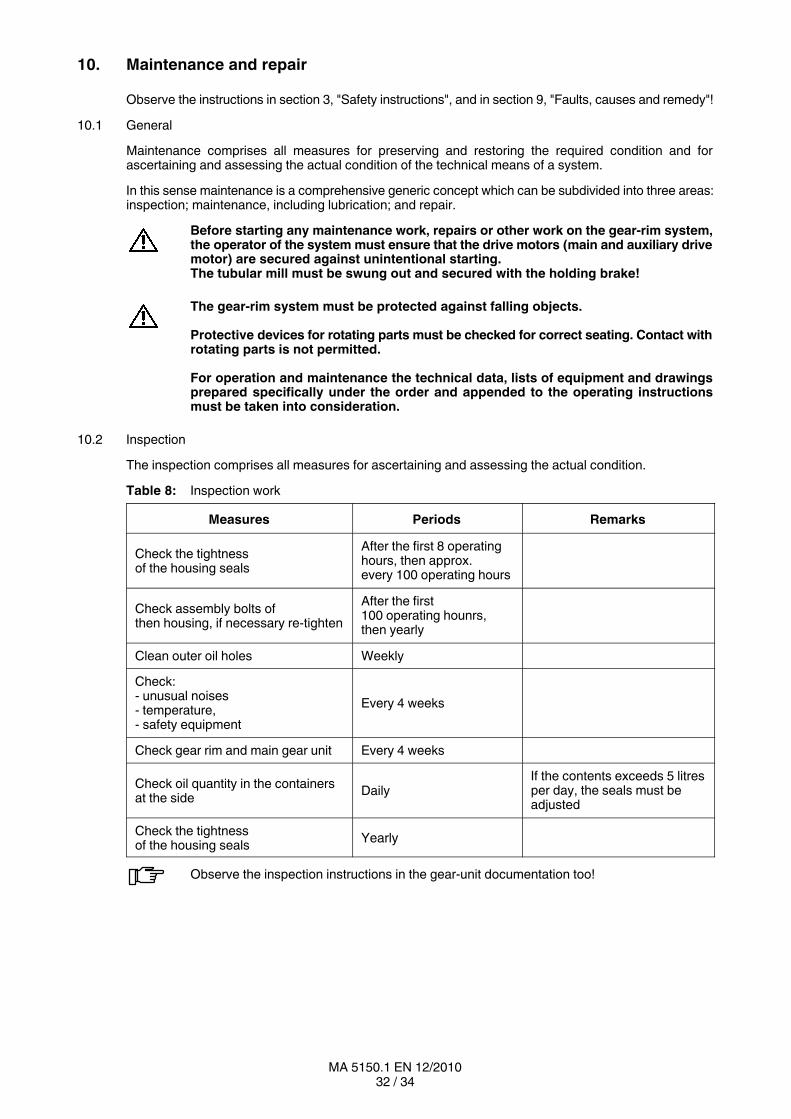
10.2 Inspection
The inspection comprises all measures for ascertaining and assessing the actual condition.
Table 8: Inspection work
Measures Periods Remarks
Check the tightnessof the housing seals
After the first 8 operatinghours, then approx.every 100 operating hours
Check assembly bolts ofthen housing, if necessary retighten
After the first100 operating hounrs,then yearly
Clean outer oil holes Weekly
Check: unusual noises temperature, safety equipment
Every 4 weeks
Check gear rim and main gear unit Every 4 weeks
Check oil quantity in the containersat the side
DailyIf the contents exceeds 5 litresper day, the seals must beadjusted
Check the tightnessof the housing seals
Yearly
Observe the inspection instructions in the gearunit documentation too!
33 / 34MA 5150.1 EN 12/2010
11. Spare parts, customerservice
11.1 Stocking spare parts
By stocking the most important spare and wearing parts on site you can ensure that the gearrim systemis ready for use at any time.
To order spare parts, refer to the spareparts list.
For further information refer to the spareparts drawing stated in the spare parts list.
We guarantee only the original spare parts supplied by us. Nonoriginal spare partshave not been tested or approved by us. They may alter technical characteristics ofthe gearrim system, thereby posing an active or passive risk to safety. Siemens willassume no liability or guarantee for damage any caused by spare parts not suppliedby Siemens. The same applies to any accessories not supplied by Siemens.
Please note that certain components often have special production and supply specifications and that wesupply you with spare parts which comply fully with the current state of technical development as well ascurrent legislation.
When ordering spare parts, always state the following:
Order number, item Type, sizePart number Quantity
11.2 Spare parts and customerservice addresses
When ordering spare parts or requesting a service specialist, please contact Siemens first (see section 2,"General notes").

Siemens AGIndustry SectorMechanical DrivesAlfred-Flender-Straße 7746395 BocholtGERMANY
www.siemens.com/drivetechnology
Subject to modifications
© Siemens AG 2010