Embed Size (px)
Citation preview
FLEX-SQUARE FLEX Light: Dynamic White Pool & Spa
© 2021 Q-Tran Inc. All rights reserved | 155 Hill St. Milford, CT 06460 | 203-367-8777 | [email protected] | www.q-tran.com Specification subject to change. Rev-08-02-21
COMPLIANT
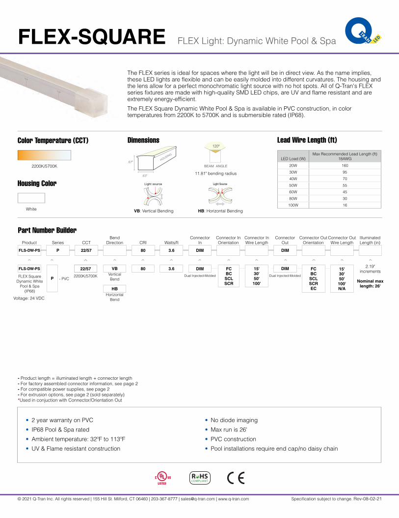
The FLEX series is ideal for spaces where the light will be in direct view. As the name implies, these LED lights are flexible and can be easily molded into different curvatures. The housing and the lens allow for a perfect monochromatic light source with no hot spots. All of Q-Tran's FLEX series fixtures are made with high-quality SMD LED chips, are UV and flame resistant and are extremely energy-efficient.
The FLEX Square Dynamic White Pool & Spa is available in PVC construction, in color temperatures from 2200K to 5700K and is submersible rated (IP68).
Part Number Builder
2200K/5700K
22/57
.67"
.63"
HOUSING
LIGHT SOURCE
120º
BEAM ANGLE
11.81" bending radius
Light SourceLight source
Color Temperature (CCT)
2200K/5700K
VB: Vertical Bending HB: Horizontal Bending
Housing Color
White
Voltage: 24 VDC
FLEX SquareDynamic White
Pool & Spa(IP68)
VBVertical Bend
HBHorizontal
Bend
2.19" increments
Nominal max length: 26'
Illuminated Length (in)
Connector In
Connector Out
DIM DIM
CCT
22/57
Series
P
P - PVC
FLS-DW-PS
Product
FLS-DW-PS
Watts/ftCRIBend
Direction
3.680 15'30'50'
100'
DIM
3.680
FCBC
SCLSCR
DIM
• 2 year warranty on PVC
• IP68 Pool & Spa rated
• Ambient temperature: 32ºF to 113ºF
• UV & Flame resistant construction
• No diode imaging
• Max run is 26'
• PVC construction
• Pool installations require end cap/no daisy chain
FCBC
SCLSCREC
15'30'50'
100'N/A
- Product length = illuminated length + connector length- For factory assembled connector information, see page 2- For compatible power supplies, see page 2- For extrusion options, see page 2 (sold separately)*Used in conjuction with Connector/Orientation Out
Dual Injected-Molded Dual Injected-Molded
Connector InOrientation
Connector OutOrientation
Connector InWire Length
Connector Out Wire Length
Dimensions Lead Wire Length (ft)
LED Load (W)Max Recommended Lead Length (ft)
18AWG
20W 160
30W 95
40W 70
50W 55
60W 45
80W 30
100W 16
FLEX-SQUARE FLEX Light: Dynamic White Pool & Spa
© 2021 Q-Tran Inc. All rights reserved | 155 Hill St. Milford, CT 06460 | 203-367-8777 | [email protected] | www.q-tran.com Specification subject to change. Rev-08-02-21
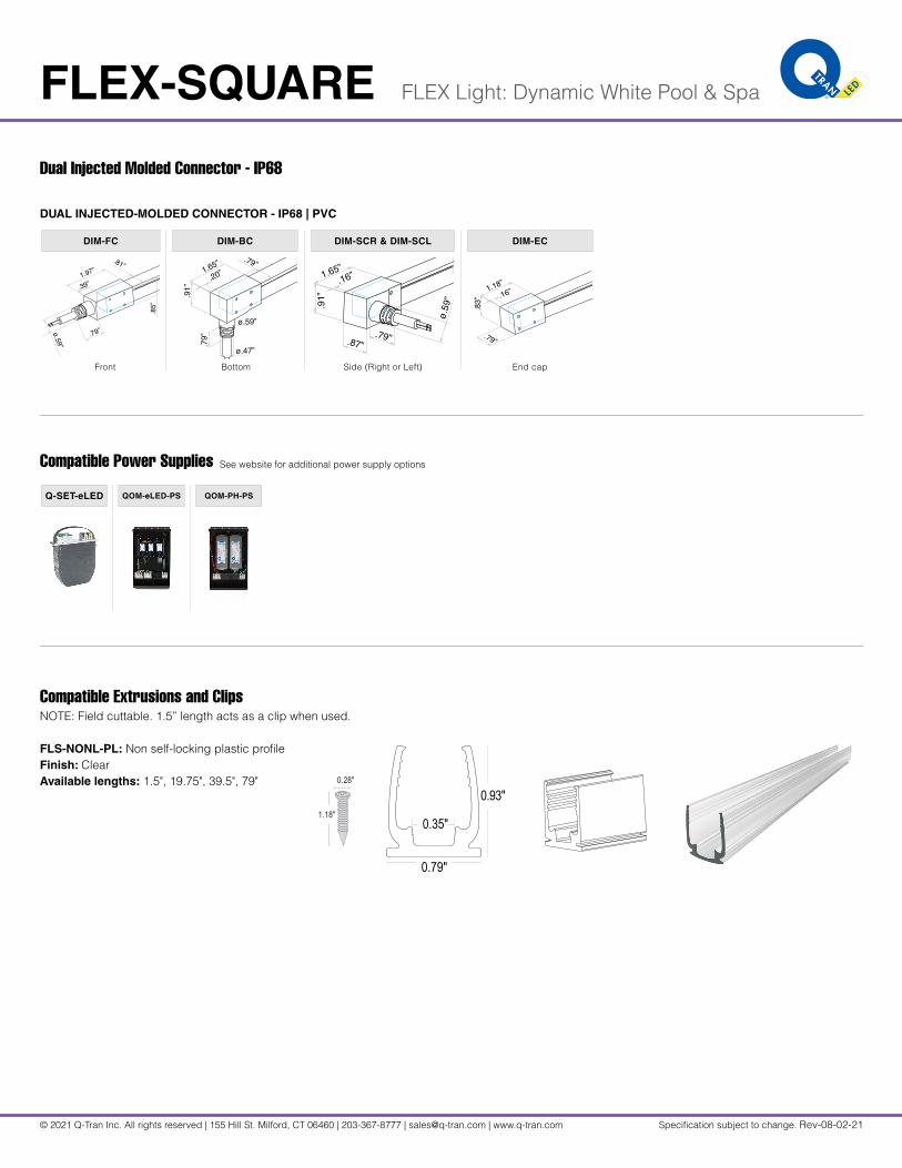
Dual Injected Molded Connector - IP68
DUAL INJECTED-MOLDED CONNECTOR - IP68 | PVC
Front Bottom Side (Right or Left) End cap
DIM-FC DIM-BC DIM-SCR & DIM-SCL DIM-EC
.85”
1.97”
.81”
.39”
.79”ø.59”
.79”
.91”
1.65”
.20”
.79”
ø.59”
ø.47”
.83”
.79”
1.18”
.16”
.91”
.87”
1.65”.16”
.79”
ø.59”
Compatible Power Supplies See website for additional power supply options
QOM-eLED-PS QOM-PH-PSQ-SET-eLED
Compatible Extrusions and ClipsNOTE: Field cuttable. 1.5” length acts as a clip when used.
0.35"
0.79"
0.93"
FLS-NONL-PL: Non self-locking plastic profileFinish: ClearAvailable lengths: 1.5", 19.75", 39.5", 79" 0.28"
1.18"
© 2020 Q-Tran Inc. All rights reserved | 155 Hill St. Milford, CT 06460 | 203-367-8777 | [email protected] | www.q-tran.com Specification subject to change. Rev-02-17-21
INSTALLATION FLEX Light - FLEX Square
NOTES: • Field modifications must comply with Q-Tran’s installation methods otherwise warranty is null and void
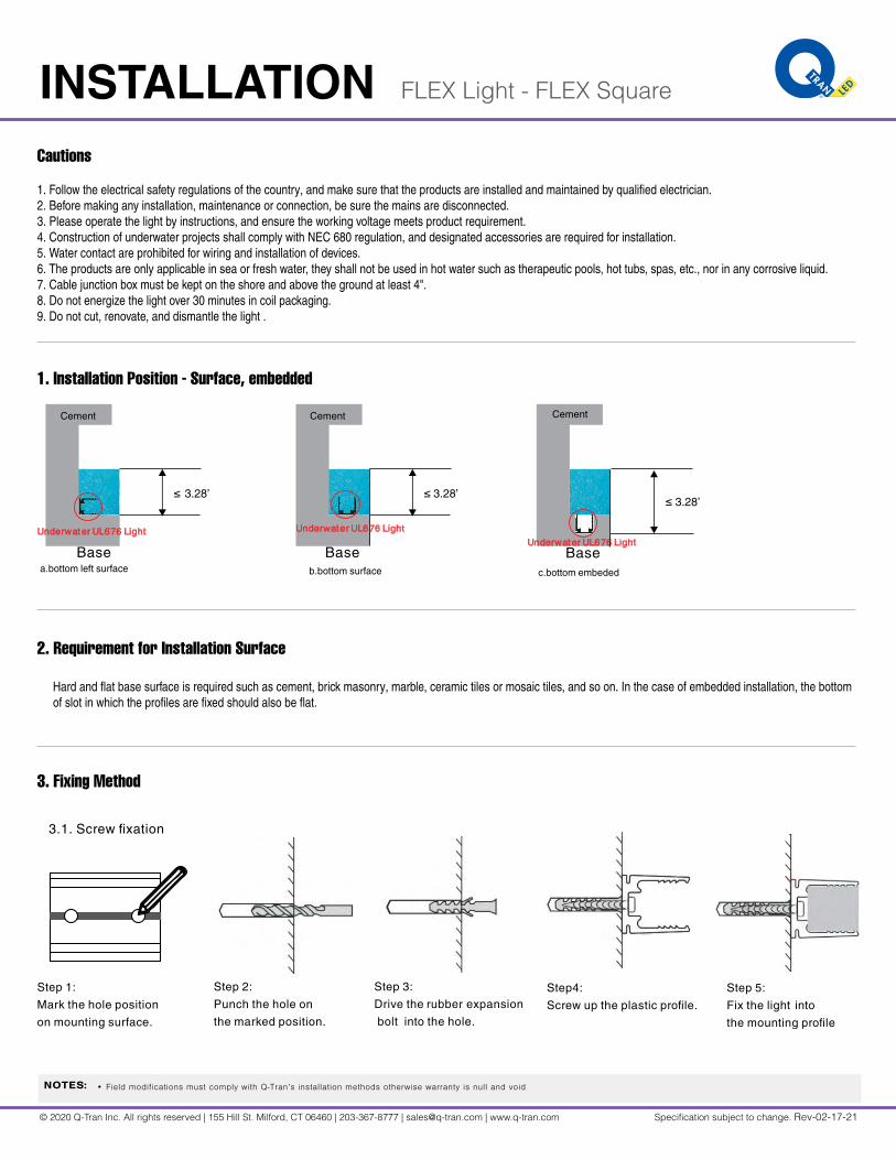
Cautions
1. Installation Position - Surface, embedded
2. Requirement for Installation Surface
Hard and flat base surface is required such as cement, brick masonry, marble, ceramic tiles or mosaic tiles, and so on. In the case of embedded installation, the bottom of slot in which the profiles are fixed should also be flat.
3. Fixing Method
1. Follow the electrical safety regulations of the country, and make sure that the products are installed and maintained by qualified electrician.2. Before making any installation, maintenance or connection, be sure the mains are disconnected.3. Please operate the light by instructions, and ensure the working voltage meets product requirement.4. Construction of underwater projects shall comply with NEC 680 regulation, and designated accessories are required for installation.5. Water contact are prohibited for wiring and installation of devices.6. The products are only applicable in sea or fresh water, they shall not be used in hot water such as therapeutic pools, hot tubs, spas, etc., nor in any corrosive liquid.7. Cable junction box must be kept on the shore and above the ground at least 4".8. Do not energize the light over 30 minutes in coil packaging.9. Do not cut, renovate, and dismantle the light .
≤
Cement
Underwater UL676 Light
Baseb.bottom surface
≤
Underwater UL676 LightBase
c.bottom embeded
Cement
Underwater UL676 Light
Base
Cement
a.bottom left surface
≤ 3.28’ 3.28’3.28’
Step 2:
Punch the hole on
the marked position.
Step 3:
Drive the expansion
bolt into the hole.
rubber Step4:
Screw up the plastic profile.
Step 5:
Fix the light into
the mounting profile
Step 1:
Mark the hole position
on mounting surface.
3.1. Screw fixation
© 2020 Q-Tran Inc. All rights reserved | 155 Hill St. Milford, CT 06460 | 203-367-8777 | [email protected] | www.q-tran.com Specification subject to change. Rev-02-17-21
INSTALLATION FLEX Light - FLEX Square
NOTES: • Field modifications must comply with Q-Tran’s installation methods otherwise warranty is null and void
3. Fixing Method
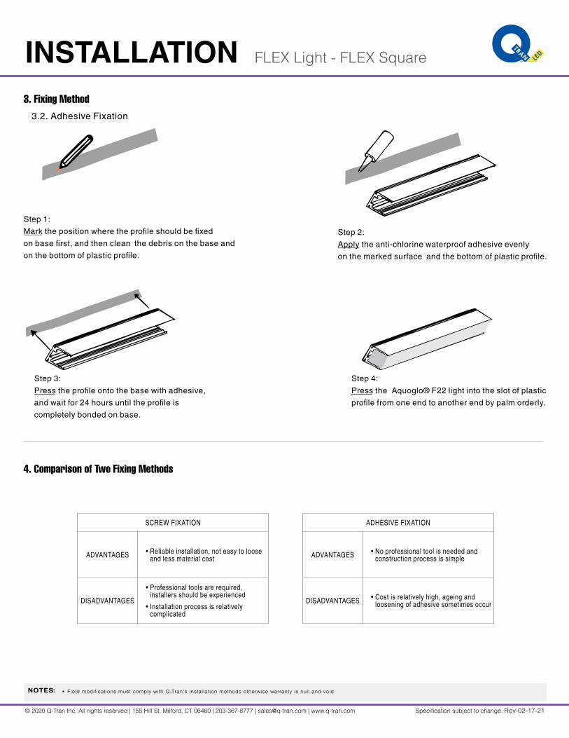
4. Comparison of Two Fixing Methods
3.2. Adhesive Fixation
Step 1:
Mark the position where the profile should be fixed
on base first, and then clean the debris on the base and
on the bottom of plastic profile.
Step 2:
Apply the anti-chlorine waterproof adhesive evenly
on the marked surface and the bottom of plastic profile.
Step 3:
Press the profile onto the base with adhesive,
and wait for 24 hours until the profile is
completely bonded on base.
Step 4:
Press the Aquoglo® F22 light into the slot of plastic
profile from one end to another end by palm orderly.
SCREW FIXATION
ADVANTAGES • Reliable installation, not easy to loose and less material cost
DISADVANTAGES
• Professional tools are required, installers should be experienced
• Installation process is relatively complicated
ADHESIVE FIXATION
ADVANTAGES • No professional tool is needed and construction process is simple
DISADVANTAGES • Cost is relatively high, ageing and loosening of adhesive sometimes occur
© 2020 Q-Tran Inc. All rights reserved | 155 Hill St. Milford, CT 06460 | 203-367-8777 | [email protected] | www.q-tran.com Specification subject to change. Rev-02-17-21
INSTALLATION FLEX Light - FLEX Square
NOTES: • Field modifications must comply with Q-Tran’s installation methods otherwise warranty is null and void
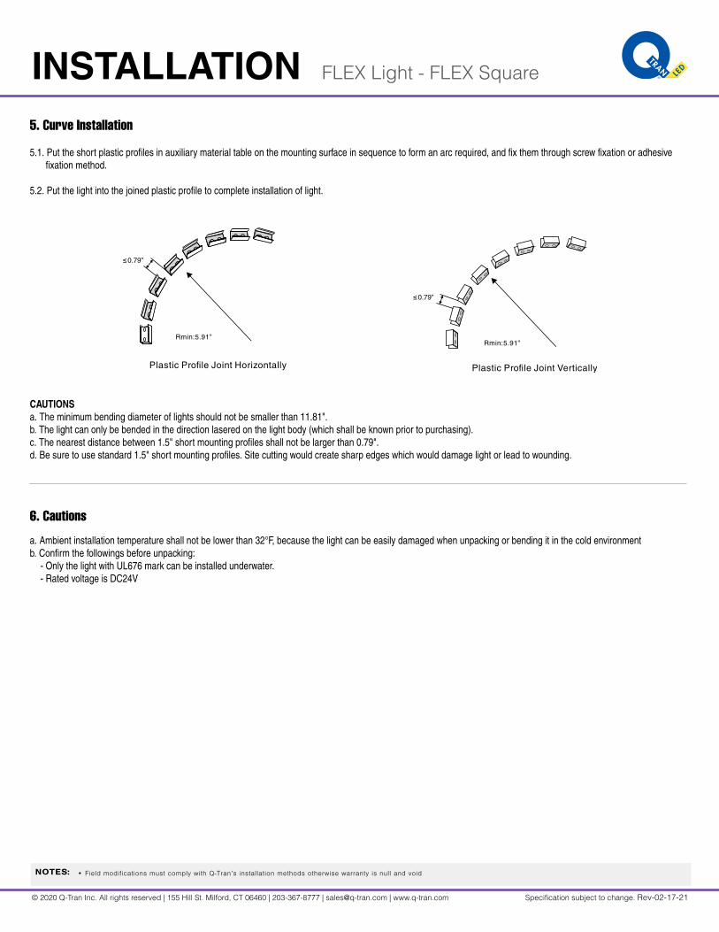
5. Curve Installation
6. Cautions
5.1. Put the short plastic profiles in auxiliary material table on the mounting surface in sequence to form an arc required, and fix them through screw fixation or adhesivefixation method.
5.2. Put the light into the joined plastic profile to complete installation of light.
CAUTIONSa. The minimum bending diameter of lights should not be smaller than 11.81". b. The light can only be bended in the direction lasered on the light body (which shall be known prior to purchasing).c. The nearest distance between 1.5" short mounting profiles shall not be larger than 0.79".d. Be sure to use standard 1.5" short mounting profiles. Site cutting would create sharp edges which would damage light or lead to wounding.
Plastic Profile Joint Horizontally Plastic Profile Joint Vertically
Rmin:5.91”Rmin:5.91”
≤0.79”
≤0.79”
a. Ambient installation temperature shall not be lower than 32°F, because the light can be easily damaged when unpacking or bending it in the cold environmentb. Confirm the followings before unpacking:
- Only the light with UL676 mark can be installed underwater.- Rated voltage is DC24V
© 2020 Q-Tran Inc. All rights reserved | 155 Hill St. Milford, CT 06460 | 203-367-8777 | [email protected] | www.q-tran.com Specification subject to change. Rev-02-17-21
INSTALLATION FLEX Light - FLEX Square
NOTES: • Field modifications must comply with Q-Tran’s installation methods otherwise warranty is null and void
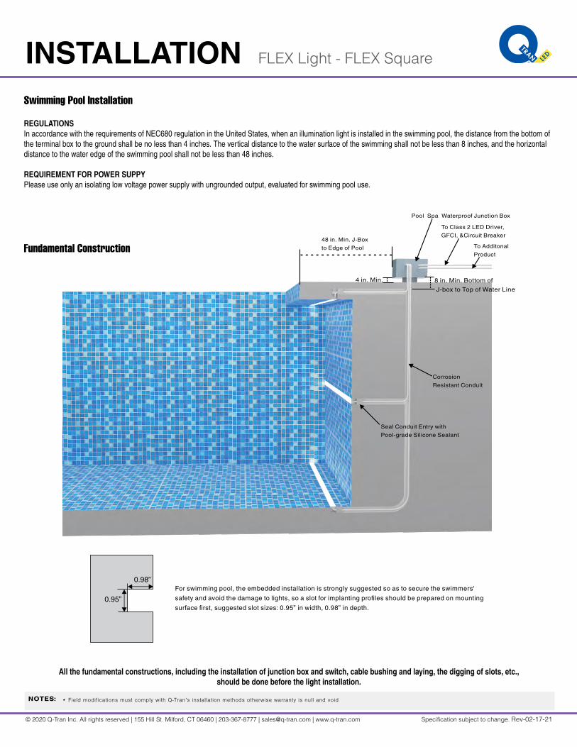
Swimming Pool Installation
Fundamental Construction
REGULATIONSIn accordance with the requirements of NEC680 regulation in the United States, when an illumination light is installed in the swimming pool, the distance from the bottom of the terminal box to the ground shall be no less than 4 inches. The vertical distance to the water surface of the swimming shall not be less than 8 inches, and the horizontal distance to the water edge of the swimming pool shall not be less than 48 inches.
REQUIREMENT FOR POWER SUPPYPlease use only an isolating low voltage power supply with ungrounded output, evaluated for swimming pool use.
All the fundamental constructions, including the installation of junction box and switch, cable bushing and laying, the digging of slots, etc., should be done before the light installation.
Pool Spa Waterproof Junction Box
Corrosion
Resistant Conduit
8 in. Min. Bottom of
J-box to Top of Water Line
48 in. Min. J-Box
to Edge of Pool
Seal Conduit Entry with
Pool-grade Silicone Sealant
To Class 2 LED Driver,
GFCI, &Circuit Breaker
To Additonal
Product
4 in. Min.
For swimming pool, the embedded installation is strongly suggested so as to secure the swimmers'
safety and avoid the damage to lights, so a slot for implanting profiles should be prepared on mounting
surface first, suggested slot sizes: 0.95” in width, 0.98” in depth.
0.98”
0.95”
© 2020 Q-Tran Inc. All rights reserved | 155 Hill St. Milford, CT 06460 | 203-367-8777 | [email protected] | www.q-tran.com Specification subject to change. Rev-02-17-21
INSTALLATION FLEX Light - FLEX Square
NOTES: • Field modifications must comply with Q-Tran’s installation methods otherwise warranty is null and void
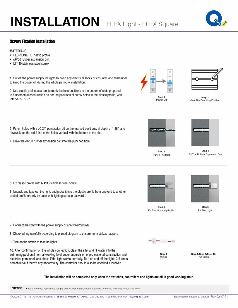
Screw Fixation Installation
MATERIALS• FLS-NONL-PL Plastic profile• ø6*30 rubber expansion bolt• M4*30 stainless steel screw
1. Cut off the power supply for lights to avoid any electrical shock or casualty, and remember to keep the power off during the whole period of installation.
2. Use plastic profile as a tool to mark the hole positions in the bottom of slots prepared in fundamental construction as per the positions of screw holes in the plastic profile, with interval of 7.87".
3. Punch holes with a ø0.24" percussion bit on the marked positions, at depth of 1.38", and always keep the axial line of the holes vertical with the bottom of the slot.
4. Drive the ø6*30 rubber expansion bolt into the punched hole.
5. Fix plastic profile with M4*30 stainless steel screw.
6. Unpack and take out the light, and press it into the plastic profile from one end to another end of profile orderly by palm with lighting surface outwards.
7. Connect the light with the power supply or controller/dimmer.
8. Check wiring carefully according to planed diagram to ensure no mistakes happen.
9. Turn on the switch to test the lights.
10. After confirmation of the whole connection, clean the site, and fill water into the swimming pool until normal working level under supervision of professional construction and electrical personnel, and check if the light works normally. Turn on and off the lights 3-5 times and observe if there's any abnormality. The controller should also be checked if involved.
The installation will be completed only when the switches, controllers and lights are all in good working state.
Step 1Power Off
Step 2Mark The Punching Position
Step 3Punch The Hole
Step 4Fit The Rubber Expansion Bolt
Step 5Fix The Mounting Profile
Step 6Fix The Light
Step 7Wiring
Step 8/Step 9/Step 10 Checkup

© 2020 Q-Tran Inc. All rights reserved | 155 Hill St. Milford, CT 06460 | 203-367-8777 | [email protected] | www.q-tran.com Specification subject to change. Rev-02-17-21
INSTALLATION FLEX Light - FLEX Square
NOTES: • Field modifications must comply with Q-Tran’s installation methods otherwise warranty is null and void
Other Installation Cases
Troubleshooting
Referring to the above installation guidance of swimming pool, the primary procedures include:
1. Read the user manual carefully, and remember the relevant safety clauses included.
2. Make the installation plan, such as wiring diagram, selection of power supply and controller, wire gauge and length, etc.
3. Installation:• Mounting Position: surface or embedded• Fixation Method: screw or adhesive• Installation Procedure:
• Mark the places where the profiles should be fixed• Fix plastic profiles through screw or adhesive• Put lights into mounting profiles properly• Connect light with power supply
4. Check, power on and test.
5. Clear the site.
TROUBLE SOLUTION
Brightness and Color Temperature Drift
• Check if the wiring cable is too thin in conductor section or too long in length.
• Check if the line has other abnormal voltage drop, and if terminal voltage is lower than 22.5V.
Some LED light sources are dark • Check if light is over bended which results in damage of inner circuit.
Light flickers abnormally• Check if power supply and dimmer are selected properly.
• Check if connection of route is in poor contact state.
Light is on and off repeatedly • Check if driver is overloaded and if the terminal voltage is lower than 22.5V.