Embed Size (px)
Citation preview
Structural Engineering Earthquake Simulation
Laboratory
212 Ketter Hall, North Campus, Buffalo, NY 14260-4300 Fax: (716) 645-3733 Tel: (716) 645 2114 X 2400
http://www.civil.buffalo.edu
S.E.E.S.L.
SEISMIC QUALIFICATION TESTS OF SPRINKLER SYSTEMS
A STUDY FOR FLEXHEAD INDUSTRIES
PART 1
Summary Report to Sponsor:
FlexHead Industries
56 Lowland Street
Holliston, MA 01746
Prepared By:
Cevdet K. Gulec, M.S., Graduate Research Assistant
Andrew Whittaker, Ph.D, S.E.
Department of Civil, Structural and Environmental Engineering
State University of New York
University at Buffalo, Buffalo, New York
October 7, 2005

Structural Engineering Earthquake Simulation
Laboratory i
S.E.E.S.L.
TABLE OF CONTENTS
TABLE OF CONTENTS i
1. INTRODUCTION 1 1.1 General 1
2. EXPERIMENTAL FIXTURE AND TEST SPECIMENS 2 2.1 Earthquake Simulator 2 2.2 Test Frame 2 2.3 Instrumentation 3 2.4 Specimen Description 8
2.4.1 Introduction 8 2.4.2 FlexHead System 1 12 2.4.3 FlexHead System 2 14
3. SEISMIC QUALIFICATION AND EARTHQUAKE HISTORIES 16 3.1 Introduction 16 3.2 Seismic Qualification of the Sprinkler and Ceiling Systems 16
3.2.1 ICC Requirements for Seismic Qualification of Nonstructural Components 16 3.2.2 Limit States of Response 16 3.2.3 Horizontal and Vertical Target Spectra for Qualification 16 3.2.4 Description of Simulation Tests 20
3.3 Earthquake Histories 21 3.3.1 White Noise 21 3.3.2 Response Spectrum Matching Procedure and Earthquake Histories 21 3.3.2.1 Ground Motion Generation 21 3.3.2.2 Ground Motion Scaling and Filtering 21 3.3.2.3 Ground Motion Generation 23 3.3.2.4 Ground Motion Scaling and Filtering 23 3.3.2.5 Earthquake Simulator Motion Verification and Analysis 23
4. SUMMARY RESULTS 26 REFERENCES 27
1
1. INTRODUCTION
1.1 General
This report describes the seismic performance of two FlexHead Industries sprinkler systems tested
together with Armstrong World Industry Inc. suspended ceiling systems at the University at Buffalo
between August 18 and August 24, 2005. The testing protocol adopted for the full-scale tests described in
this summary report is that prepared by the International Code Council, which is entitled ICC AC156,
Seismic Qualification Testing of Nonstructural Components (ICC, 2004), which is denoted hereafter as
AC156.
A number of studies related to the seismic performance of Armstrong World Industry Inc. suspended
ceiling systems have been completed in recent years (incl. Repp et al., 2003a, 2003b; Badillo et al., 2002,
2003a, 2003b; Kusumastuti et al., 2002; Cyr et al., 2004; Gulec et al. 2005). However, the studies
reported herein are the first conducted on a large-scale ceiling assembly including lay-in tiles and
sprinkler lines and heads.
Chapter 2 of the report describes the earthquake simulator, the test frame and the FlexHead systems.
Chapter 3 introduces the topic of seismic qualification and describes the earthquake histories used in the
testing program. Summary results are presented in Chapter 4. References are provided following Chapter
4.
Additional information on the tests reported herein will be presented in SEESL technical reports that are
being prepared at the time of this writing.
2
2. EXPERIMENTAL FIXTURE AND TEST SPECIMENS
2.1 Earthquake Simulator
One of the two six degrees-of-freedom earthquake simulators in the Structural Engineering and
Earthquake Simulation Laboratory (SEESL) of the State University of New York at Buffalo was used to
evaluate the FlexHead sprinkler systems. These two simulators can be rapidly repositioned from directly
adjacent to one another to positions up to 100 ft (30.48 m) apart. Together, these tables can host
specimens of up to 220.5 kips (981 kN) and as long as 120 ft (36.6 m), and subject them fully in-phase or
totally uncorrelated dynamic excitations. Each earthquake simulator has plan dimensions of 11.8 ft x 11.8
ft (3.6 m x 3.6 m) and is made of a welded steel construction with a weight of approximately 17.6 kips
(78 kN). A steel testing platform of plan dimensions 23 ft. (7.01 m) by 23 ft. (7.01 m) extends the useful
testing area of the simulator. The Hydraulic Power Supply (HPS) subsystem for both simulators consists
of four MTS Model 506.92 pumps rated at 185 gpm (700 lpm) at 3,000 psi (207 bar) each. Additional
information can be found at www.nees.buffalo.edu.
The two six degrees-of-freedom earthquake simulators are designed for the nominal performance shown
in Table 2.1. These performance data are based on uniaxial sinusoidal motion of the simulator with a rigid
44.1 kip (196 kN) payload. System performance levels are reduced with payloads larger than a nominal
payload. Acceptance testing of the simulators has verified a frequency response of 0-100 Hz with the bare
platform and 0-50 Hz with a 44.1 kip (196 kN) payload. Input or command signals to the table can be of
the following types: harmonic motions (sinusoidal, square, and triangular), random motions, and any
recorded earthquake history.
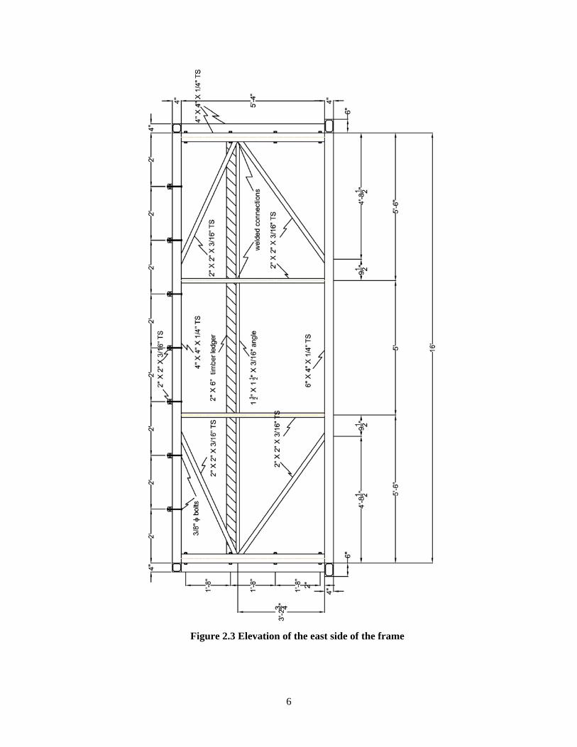
2.2 Test Frame
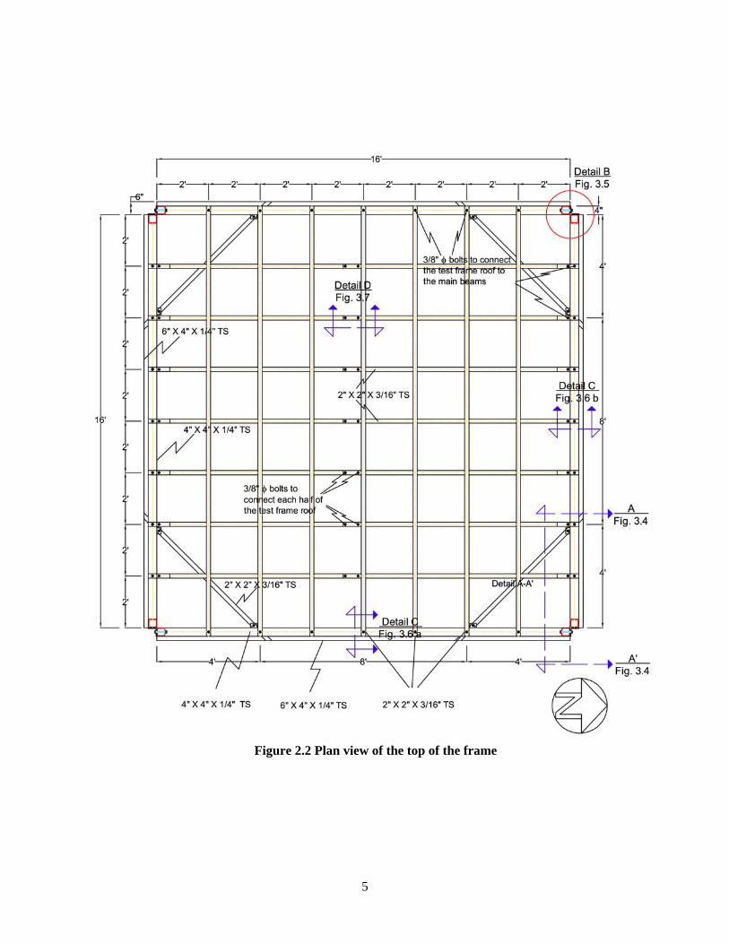
A 16 ft. (4.88 m) by 16 ft. (4.88 m) square frame of ASTM Grade 50 steel was used to test all eight
FlexHead systems. Figures 2.1 through 2.3 present detailed information on the frame. Figure 2.1 is a plan
view of the base of the frame. The frame was attached to the simulator platform using 1 in. (25 mm)
diameter bolts in the beams that were oriented in the east-west direction. Figure 2.2 shows the details of
the top of the frame. The ceiling and sprinkler systems were installed then constructed inside of the test
frame. Some ceiling systems were attached to the inside face of the 2 in. x 6 in. (51 mm x 152 mm)
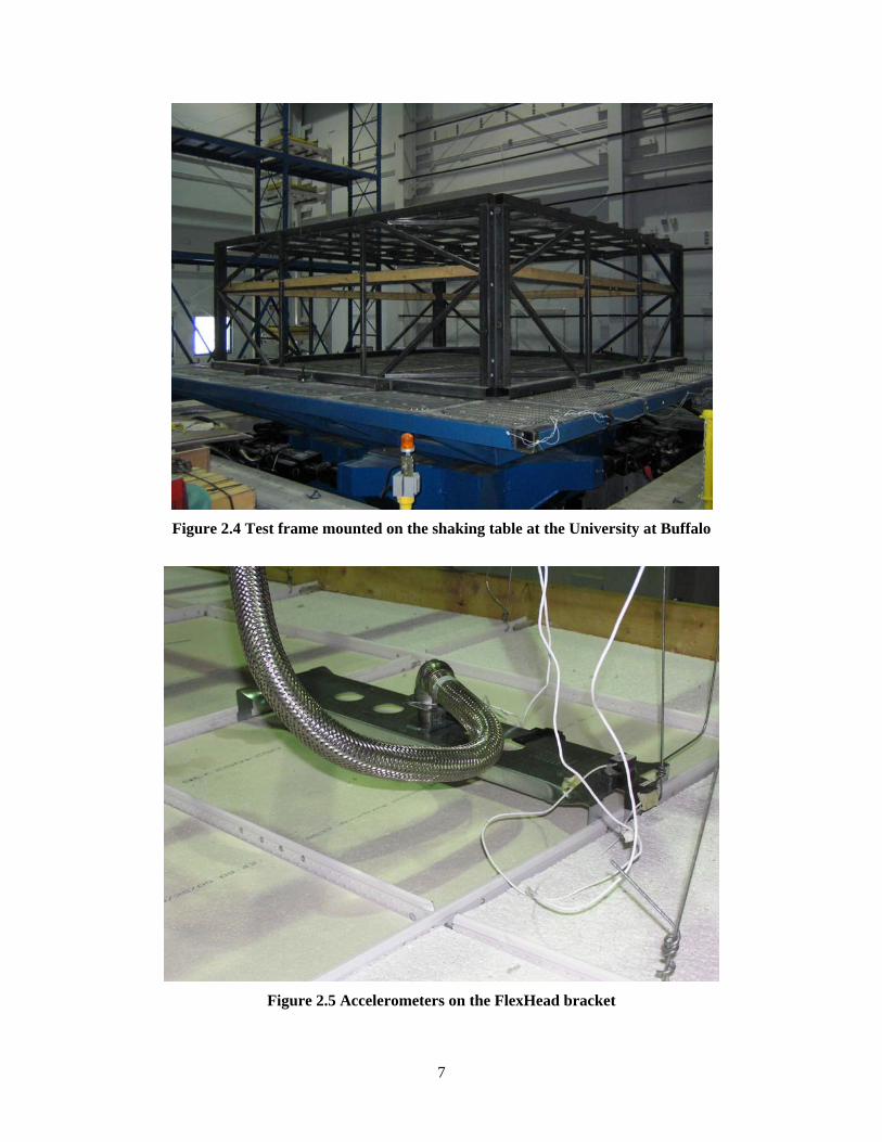
timber ledger shown in Figure 2.3. Figure 2.4 is a photograph of the test frame mounted on the earthquake
simulator.
3
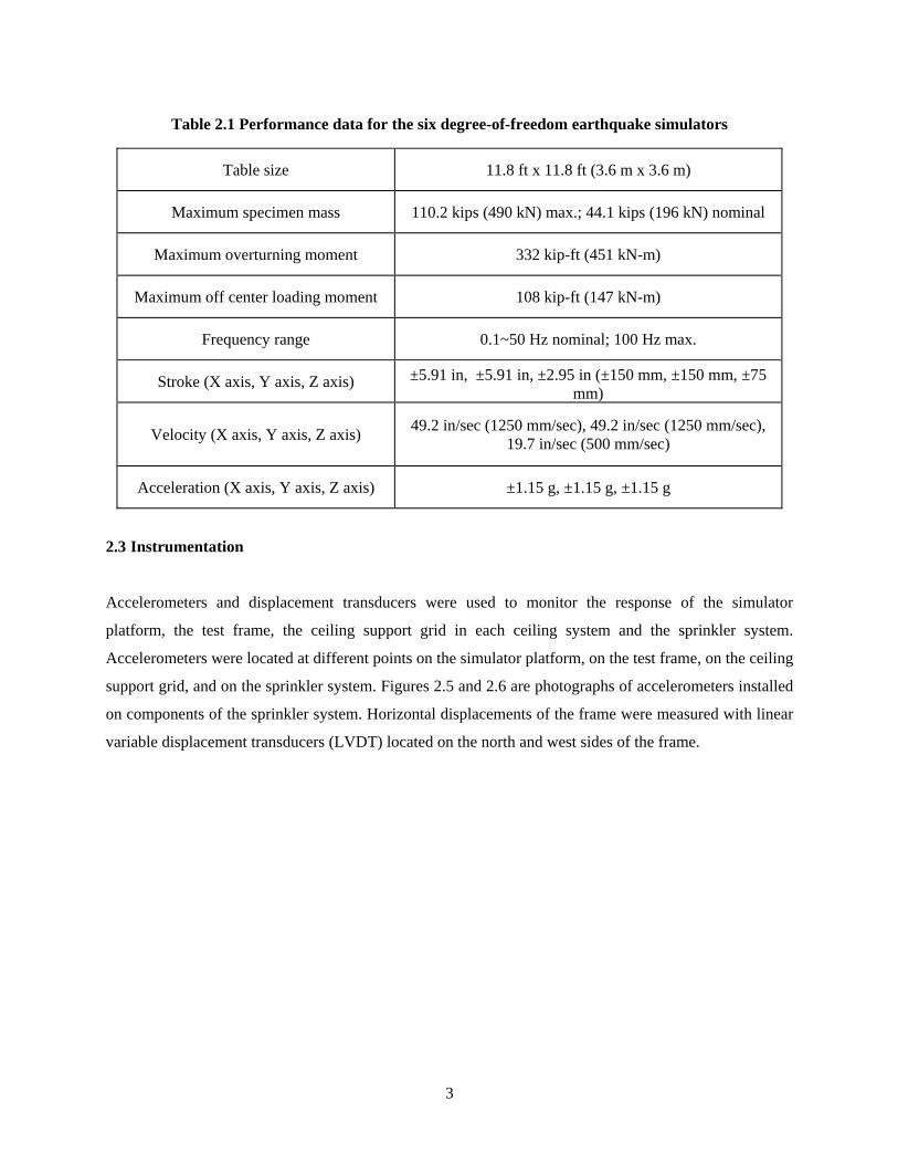
Table 2.1 Performance data for the six degree-of-freedom earthquake simulators
Table size 11.8 ft x 11.8 ft (3.6 m x 3.6 m)
Maximum specimen mass 110.2 kips (490 kN) max.; 44.1 kips (196 kN) nominal
Maximum overturning moment 332 kip-ft (451 kN-m)
Maximum off center loading moment 108 kip-ft (147 kN-m)
Frequency range 0.1~50 Hz nominal; 100 Hz max.
Stroke (X axis, Y axis, Z axis) ±5.91 in, ±5.91 in, ±2.95 in (±150 mm, ±150 mm, ±75 mm)
Velocity (X axis, Y axis, Z axis) 49.2 in/sec (1250 mm/sec), 49.2 in/sec (1250 mm/sec), 19.7 in/sec (500 mm/sec)
Acceleration (X axis, Y axis, Z axis) ±1.15 g, ±1.15 g, ±1.15 g
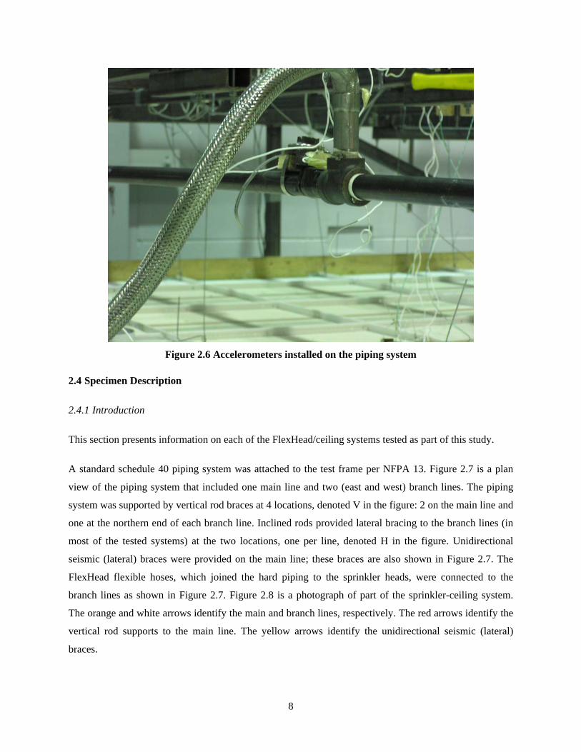
2.3 Instrumentation
Accelerometers and displacement transducers were used to monitor the response of the simulator
platform, the test frame, the ceiling support grid in each ceiling system and the sprinkler system.
Accelerometers were located at different points on the simulator platform, on the test frame, on the ceiling
support grid, and on the sprinkler system. Figures 2.5 and 2.6 are photographs of accelerometers installed
on components of the sprinkler system. Horizontal displacements of the frame were measured with linear
variable displacement transducers (LVDT) located on the north and west sides of the frame.

4
Figure 2.1 Plan view of the base of the frame
5
Figure 2.2 Plan view of the top of the frame
6
Figure 2.3 Elevation of the east side of the frame
7
Figure 2.4 Test frame mounted on the shaking table at the University at Buffalo
Figure 2.5 Accelerometers on the FlexHead bracket
8
Figure 2.6 Accelerometers installed on the piping system
2.4 Specimen Description
2.4.1 Introduction
This section presents information on each of the FlexHead/ceiling systems tested as part of this study.
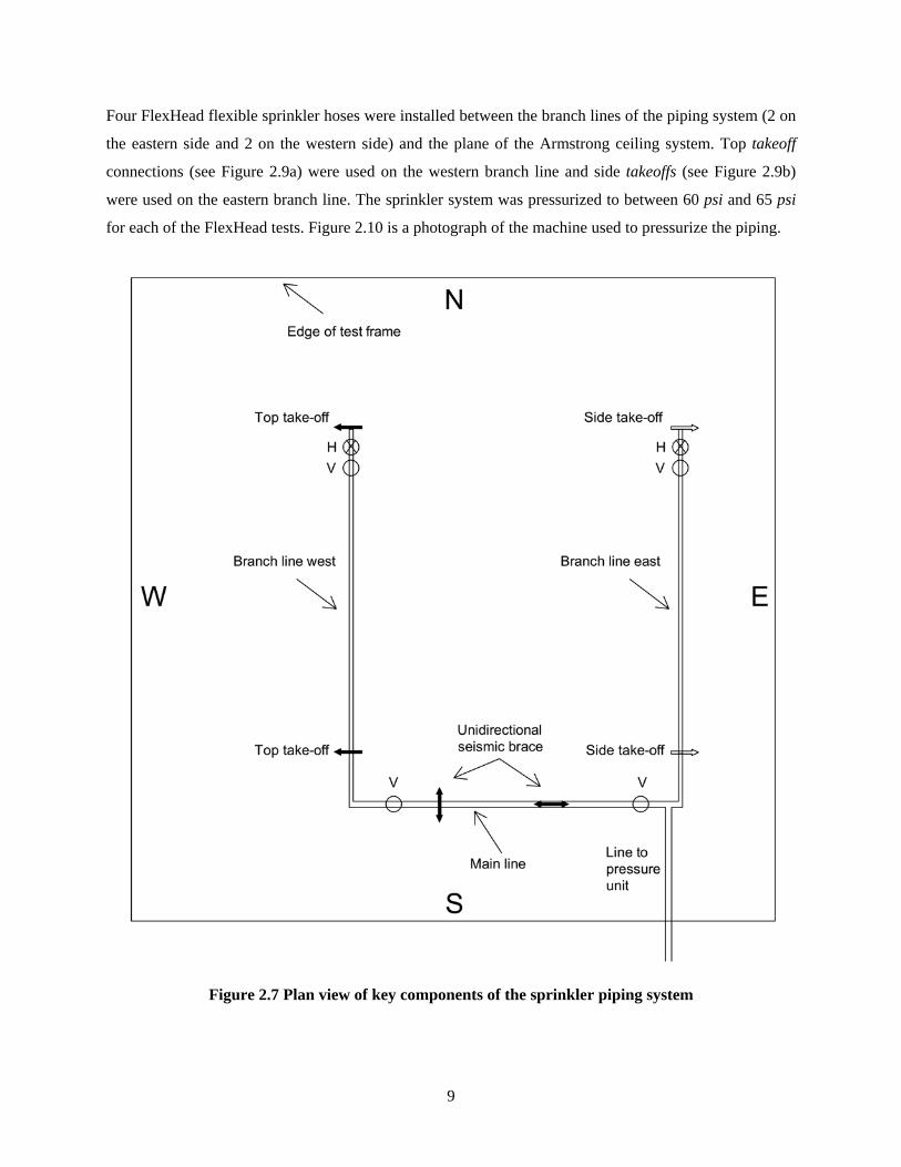
A standard schedule 40 piping system was attached to the test frame per NFPA 13. Figure 2.7 is a plan
view of the piping system that included one main line and two (east and west) branch lines. The piping
system was supported by vertical rod braces at 4 locations, denoted V in the figure: 2 on the main line and
one at the northern end of each branch line. Inclined rods provided lateral bracing to the branch lines (in
most of the tested systems) at the two locations, one per line, denoted H in the figure. Unidirectional
seismic (lateral) braces were provided on the main line; these braces are also shown in Figure 2.7. The
FlexHead flexible hoses, which joined the hard piping to the sprinkler heads, were connected to the
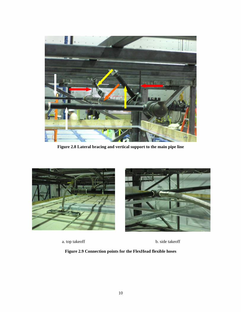
branch lines as shown in Figure 2.7. Figure 2.8 is a photograph of part of the sprinkler-ceiling system.
The orange and white arrows identify the main and branch lines, respectively. The red arrows identify the
vertical rod supports to the main line. The yellow arrows identify the unidirectional seismic (lateral)
braces.
9
Four FlexHead flexible sprinkler hoses were installed between the branch lines of the piping system (2 on
the eastern side and 2 on the western side) and the plane of the Armstrong ceiling system. Top takeoff
connections (see Figure 2.9a) were used on the western branch line and side takeoffs (see Figure 2.9b)
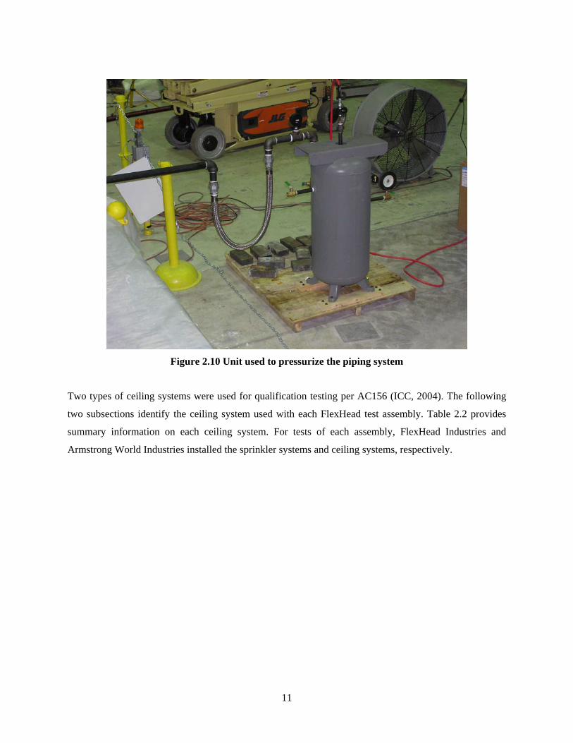
were used on the eastern branch line. The sprinkler system was pressurized to between 60 psi and 65 psi
for each of the FlexHead tests. Figure 2.10 is a photograph of the machine used to pressurize the piping.
Figure 2.7 Plan view of key components of the sprinkler piping system
10
Figure 2.8 Lateral bracing and vertical support to the main pipe line
a. top takeoff b. side takeoff
Figure 2.9 Connection points for the FlexHead flexible hoses
11
Figure 2.10 Unit used to pressurize the piping system
Two types of ceiling systems were used for qualification testing per AC156 (ICC, 2004). The following
two subsections identify the ceiling system used with each FlexHead test assembly. Table 2.2 provides
summary information on each ceiling system. For tests of each assembly, FlexHead Industries and
Armstrong World Industries installed the sprinkler systems and ceiling systems, respectively.
12
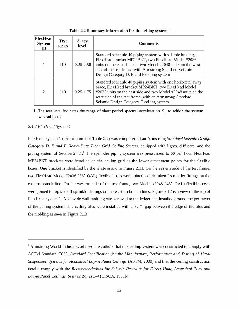
Table 2.2 Summary information for the ceiling systems
FlexHead System
ID
Test series
SS test level1 Comments
1 I10 0.25-2.50
Standard schedule 40 piping system with seismic bracing, FlexHead bracket MP24BKT, two FlexHead Model #2036 units on the east side and two Model #2048 units on the west side of the test frame, with Armstrong Standard Seismic Design Category D, E and F ceiling system
2 J10 0.25-1.75
Standard schedule 40 piping system with one horizontal sway brace, FlexHead bracket MP24BKT, two FlexHead Model #2036 units on the east side and two Model #2048 units on the west side of the test frame, with an Armstrong Standard Seismic Design Category C ceiling system
1. The test level indicates the range of short period spectral acceleration sS to which the system
was subjected.
2.4.2 FlexHead System 1
FlexHead system 1 (see column 1 of Table 2.2) was composed of an Armstrong Standard Seismic Design
Category D, E and F Heavy-Duty T-bar Grid Ceiling System, equipped with lights, diffusers, and the
piping system of Section 2.4.1.1 The sprinkler piping system was pressurized to 60 psi. Four FlexHead
MP24BKT brackets were installed on the ceiling grid as the lower attachment points for the flexible
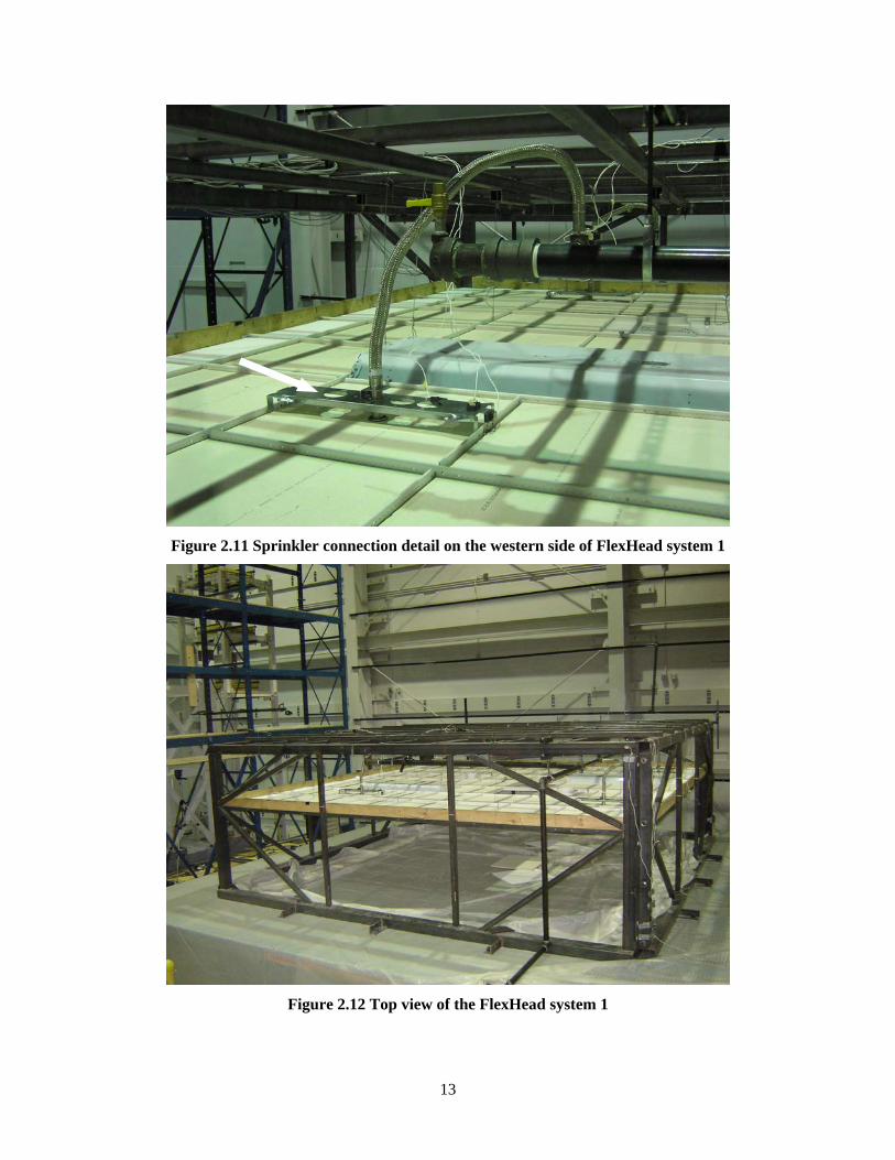
hoses. One bracket is identified by the white arrow in Figure 2.11. On the eastern side of the test frame,
two FlexHead Model #2036 ( 36′′ OAL) flexible hoses were joined to side takeoff sprinkler fittings on the
eastern branch line. On the western side of the test frame, two Model #2048 ( 48′′ OAL) flexible hoses
were joined to top takeoff sprinkler fittings on the western branch lines. Figure 2.12 is a view of the top of
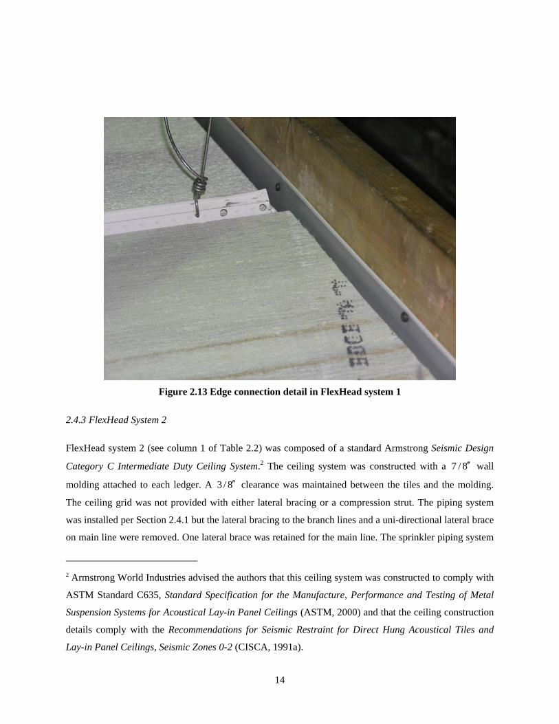
FlexHead system 1. A 2” wide wall molding was screwed to the ledger and installed around the perimeter
of the ceiling system. The ceiling tiles were installed with a 3 / 4′′ gap between the edge of the tiles and
the molding as seen in Figure 2.13.
1 Armstrong World Industries advised the authors that this ceiling system was constructed to comply with
ASTM Standard C635, Standard Specification for the Manufacture, Performance and Testing of Metal
Suspension Systems for Acoustical Lay-in Panel Ceilings (ASTM, 2000) and that the ceiling construction
details comply with the Recommendations for Seismic Restraint for Direct Hung Acoustical Tiles and
Lay-in Panel Ceilings, Seismic Zones 3-4 (CISCA, 1991b).
13
Figure 2.11 Sprinkler connection detail on the western side of FlexHead system 1
Figure 2.12 Top view of the FlexHead system 1
14
Figure 2.13 Edge connection detail in FlexHead system 1
2.4.3 FlexHead System 2
FlexHead system 2 (see column 1 of Table 2.2) was composed of a standard Armstrong Seismic Design
Category C Intermediate Duty Ceiling System.2 The ceiling system was constructed with a 7 / 8′′ wall
molding attached to each ledger. A 3 / 8′′ clearance was maintained between the tiles and the molding.
The ceiling grid was not provided with either lateral bracing or a compression strut. The piping system
was installed per Section 2.4.1 but the lateral bracing to the branch lines and a uni-directional lateral brace
on main line were removed. One lateral brace was retained for the main line. The sprinkler piping system
2 Armstrong World Industries advised the authors that this ceiling system was constructed to comply with
ASTM Standard C635, Standard Specification for the Manufacture, Performance and Testing of Metal
Suspension Systems for Acoustical Lay-in Panel Ceilings (ASTM, 2000) and that the ceiling construction
details comply with the Recommendations for Seismic Restraint for Direct Hung Acoustical Tiles and
Lay-in Panel Ceilings, Seismic Zones 0-2 (CISCA, 1991a).

15
was pressurized to 65 psi. Four FlexHead MP24BKT brackets were installed on the ceiling grid as the
lower attachment points for the flexible hoses. On the eastern side of the test frame, two FlexHead Model
#2036 ( 36′′ OAL) flexible hoses were joined to side takeoff sprinkler fittings on the eastern branch line.
On the western side of the test frame, two Model #2048 ( 48′′ OAL) flexible hoses were joined to top
takeoff sprinkler fittings on the western branch lines.
16
3. SEISMIC QUALIFICATION AND EARTHQUAKE HISTORIES
3.1 Introduction
Each of the FlexHead sprinkler systems described in Chapter 2 was subjected to a set of combined
horizontal and vertical earthquake excitations for the purpose of qualification. The qualification
procedures were those of the ICC AC156 Seismic Qualification Testing of Nonstructural Components
(ICC, 2004), which is denoted hereafter by AC156. The following section in this report presents summary
information on seismic qualification and the earthquake histories used for the qualification of the
sprinkler and ceiling systems.
3.2 Seismic Qualification of the Sprinkler and Ceiling Systems
3.2.1 ICC Requirements for Seismic Qualification of Nonstructural Components
Several requirements must be fulfilled for testing nonstructural components per AC156. As part of these
requirements, a general description of the system to be tested must be provided (see Chapter 2). This
description must include the primary equipment product function, overall dimensions, weight and
restrictions or limitations on equipment use. Seismic parameters must also be provided, such as
equipment attachment elevation, structure roof elevation, seismic coefficient and equipment importance
factor. The test specimen must also adequately represent the entire equipment product line (to be provided
by the manufacturer, FlexHead Industries, see Chapter 2).
To qualify a test system, ICC writes that the system must be subjected to a testing program that includes a
pre-test inspection and functional compliance check, resonance search tests, random multi-frequency
seismic simulation tests, and a post-test inspection and a functional compliance check.
3.2.2 Limit States of Response
Limits states of response must be defined for qualification testing; where a limit state is a boundary
between acceptable and unacceptable performance. For this testing program, three limit states were
identified: 1) water leakage from any component of the piping system, 2) movement of the sprinkler head
from its intended location, and 3) ceiling system integrity, herein defined as failure of the suspension grid.
3.2.3 Horizontal and Vertical Target Spectra for Qualification
The earthquake excitations used for the qualification of the ceiling system were obtained using the
spectrum matching procedure recommended by ICC. The first step in the process is to define a target
17
spectrum or required response spectrum (RRS). Per ICC, the RRS is obtained as a function of the mapped
spectral acceleration at short period, sS . Spectra are generated for horizontal and vertical design basis
earthquake shaking.3
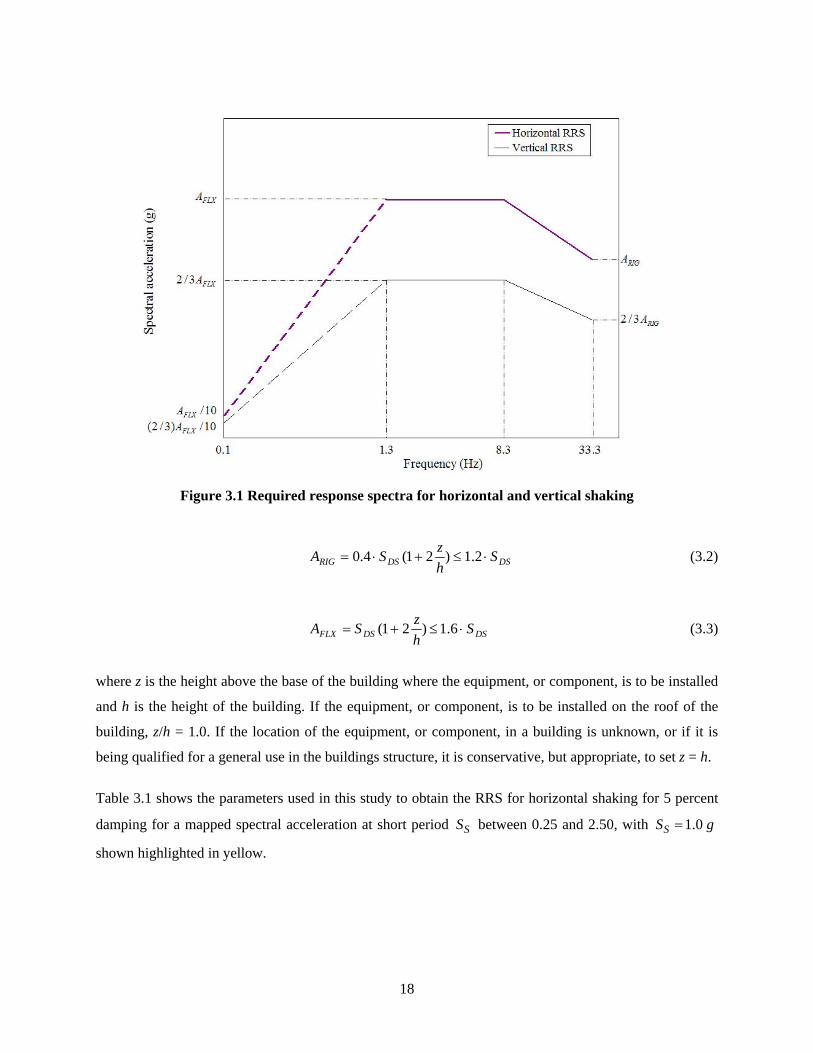
The required response spectrum for horizontal shaking was developed using the normalized ICC response
spectrum shown in Figure 3.1. (The ordinates in the range of frequency from 0.1 Hz to 1.3 Hz are
recommendations only.) The values of the parameters RIGA and FLXA that define the ordinates of the
horizontal spectrum are calculated with equations presented below.
For horizontal design basis earthquake shaking, the International Building Code (IBC, 2003) defines the
short period design basis earthquake acceleration response as:
SaDS SFS32
= (3.1)
where DSS is the design spectral response acceleration at short periods, aF is the site coefficient, and
SS is the mapped maximum earthquake spectral acceleration at short periods. Based on AC156, the
spectral acceleration RIGA of a rigid component (assumed to have a frequency f ≥ 33 Hz) is given by
(3.2) and that of a flexible component FLXA is given by (3.3).
3 The 2003 NEHRP Recommended Provisions for Seismic Regulations for New Buildings and Other
Structures (FEMA, 2003) use Seismic Design Categories (A through F) as a means of classifying a
structure based on its Seismic Use Group and the severity of the design earthquake ground motion at the
building site. As general guidance (Bachman, 2005) and based on short period response accelerations, site
classes B through D (see Table 4.1.2.4a of FEMA, 2003) and Seismic Use Groups I through III, buildings
assigned to Seismic Design Category (SDC) C have values of 0.16 0.75SS≤ ≤ g, buildings assigned to
SDC D have values of 0.33 1.70SS≤ ≤ g, and buildings assigned to SDC E or F have values of
1.50 2.40SS≤ ≤ g. Nonstructural components such as ceilings and sprinkler systems that qualify at a level
of 0.75sS ≥ g should satisfy the requirements for SDC C regardless of the site of the building. Similarly,
nonstructural components that qualify at a level of 1.70SS ≥ g and 2.40SS ≥ g, should meet the
requirements for SDC D and E/F, respectively, regardless of the site of the building. For a project-specific
design, values of spectral demand for nonstructural components should be checked on the basis of the
location of the site of the building, site class, Seismic Use Group and location of the component within
the building, all as presented in FEMA (2003).
18
Figure 3.1 Required response spectra for horizontal and vertical shaking
DSDSRIG ShzSA ⋅≤+⋅= 2.1)21(4.0 (3.2)
DSDSFLX ShzSA ⋅≤+= 6.1)21( (3.3)
where z is the height above the base of the building where the equipment, or component, is to be installed
and h is the height of the building. If the equipment, or component, is to be installed on the roof of the
building, z/h = 1.0. If the location of the equipment, or component, in a building is unknown, or if it is
being qualified for a general use in the buildings structure, it is conservative, but appropriate, to set z = h.
Table 3.1 shows the parameters used in this study to obtain the RRS for horizontal shaking for 5 percent
damping for a mapped spectral acceleration at short period SS between 0.25 and 2.50, with 1.0SS g=
shown highlighted in yellow.
19
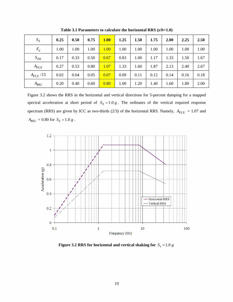
Table 3.1 Parameters to calculate the horizontal RRS (z/h=1.0)
SS 0.25 0.50 0.75 1.00 1.25 1.50 1.75 2.00 2.25 2.50
aF 1.00 1.00 1.00 1.00 1.00 1.00 1.00 1.00 1.00 1.00
DSS 0.17 0.33 0.50 0.67 0.83 1.00 1.17 1.33 1.50 1.67
FLXA 0.27 0.53 0.80 1.07 1.33 1.60 1.87 2.13 2.40 2.67
/15FLXA 0.02 0.04 0.05 0.07 0.09 0.11 0.12 0.14 0.16 0.18
RIGA 0.20 0.40 0.60 0.80 1.00 1.20 1.40 1.60 1.80 2.00
Figure 3.2 shows the RRS in the horizontal and vertical directions for 5-percent damping for a mapped
spectral acceleration at short period of 1.0SS g= . The ordinates of the vertical required response
spectrum (RRS) are given by ICC as two-thirds (2/3) of the horizontal RRS. Namely, FLXA = 1.07 and
RIGA = 0.80 for 1.0SS g= .
Figure 3.2 RRS for horizontal and vertical shaking for 1.0sS g=
20
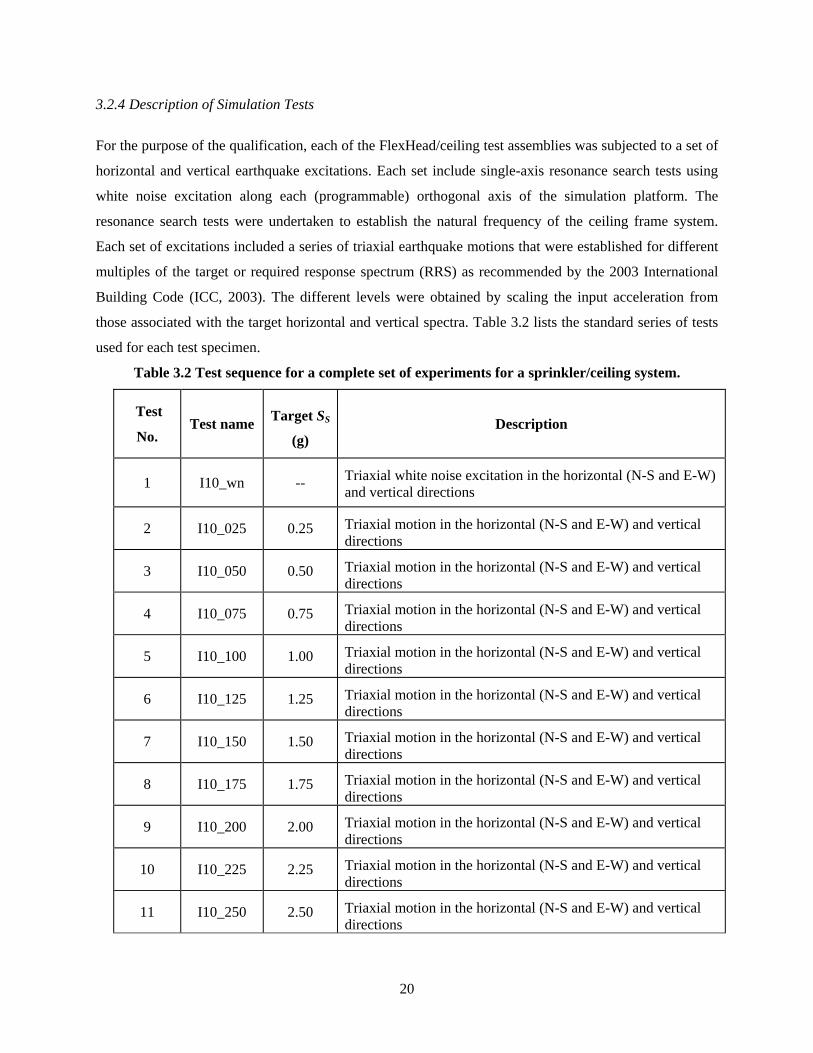
3.2.4 Description of Simulation Tests
For the purpose of the qualification, each of the FlexHead/ceiling test assemblies was subjected to a set of
horizontal and vertical earthquake excitations. Each set include single-axis resonance search tests using
white noise excitation along each (programmable) orthogonal axis of the simulation platform. The
resonance search tests were undertaken to establish the natural frequency of the ceiling frame system.
Each set of excitations included a series of triaxial earthquake motions that were established for different
multiples of the target or required response spectrum (RRS) as recommended by the 2003 International
Building Code (ICC, 2003). The different levels were obtained by scaling the input acceleration from
those associated with the target horizontal and vertical spectra. Table 3.2 lists the standard series of tests
used for each test specimen.
Table 3.2 Test sequence for a complete set of experiments for a sprinkler/ceiling system.
Test
No. Test name Target SS
(g) Description
1 I10_wn -- Triaxial white noise excitation in the horizontal (N-S and E-W) and vertical directions
2 I10_025 0.25 Triaxial motion in the horizontal (N-S and E-W) and vertical directions
3 I10_050 0.50 Triaxial motion in the horizontal (N-S and E-W) and vertical directions
4 I10_075 0.75 Triaxial motion in the horizontal (N-S and E-W) and vertical directions
5 I10_100 1.00 Triaxial motion in the horizontal (N-S and E-W) and vertical directions
6 I10_125 1.25 Triaxial motion in the horizontal (N-S and E-W) and vertical directions
7 I10_150 1.50 Triaxial motion in the horizontal (N-S and E-W) and vertical directions
8 I10_175 1.75 Triaxial motion in the horizontal (N-S and E-W) and vertical directions
9 I10_200 2.00 Triaxial motion in the horizontal (N-S and E-W) and vertical directions
10 I10_225 2.25 Triaxial motion in the horizontal (N-S and E-W) and vertical directions
11 I10_250 2.50 Triaxial motion in the horizontal (N-S and E-W) and vertical directions
21
3.3 Earthquake Histories
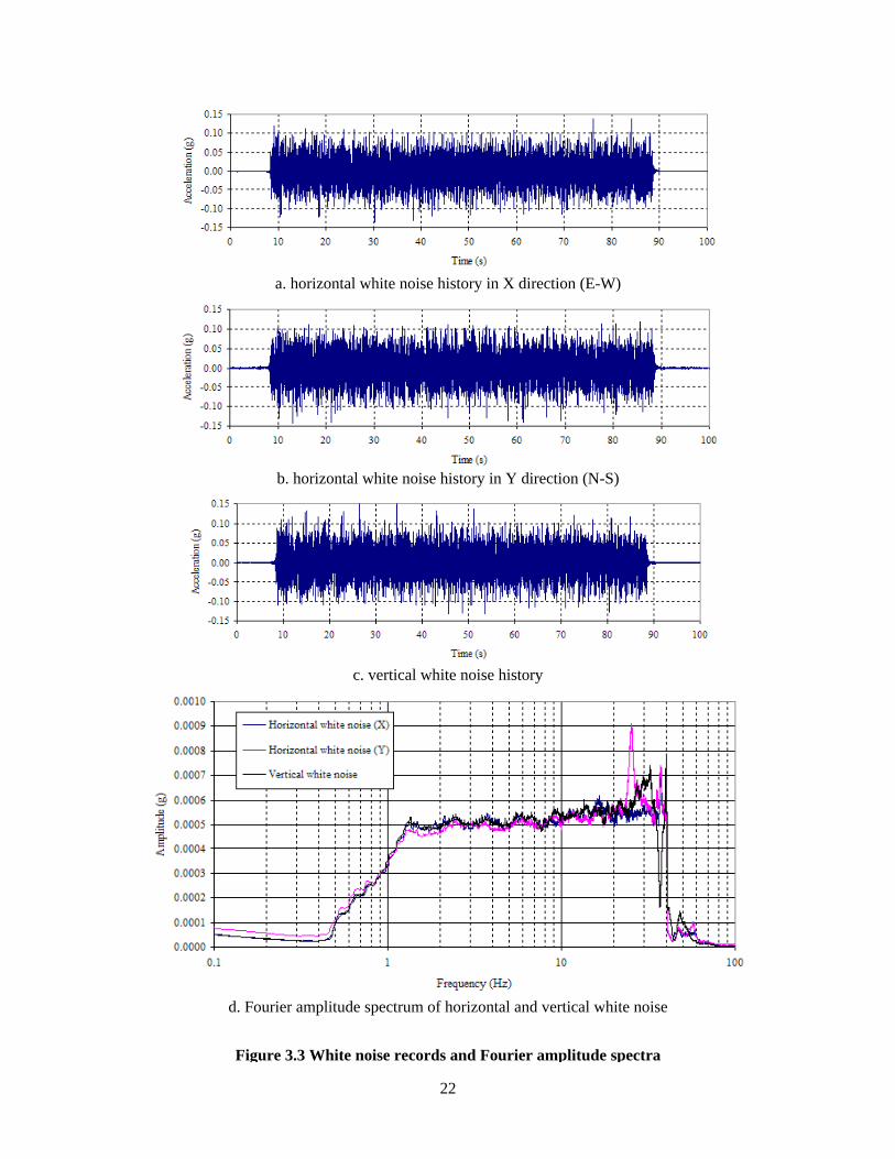
3.3.1 White Noise
White noise was used to find the frequencies of the test frame and the ceiling systems with the FlexHead
sprinkler systems. The natural frequencies for the horizontal and vertical directions of each test specimen
were obtained by finding the frequency associated with the peak in the acceleration transfer function
(Clough and Penzien, 1993). Figure 3.3 shows the records and the Fourier amplitude spectrum of the
white noise used in this study to calculate the natural frequencies of each of the ceiling systems for the
horizontal and vertical directions, respectively. These frequencies will be presented in a later report to the
sponsor, FlexHead Industries.
3.3.2 Response Spectrum Matching Procedure and Earthquake Histories
3.3.2.1 Ground Motion Generation
The earthquake excitations used for the qualification of the sprinkler systems were generated according to
the requirements of AC156 using a spectrum-matching procedure, namely, the “Inverse Response
Spectrum Procedure” (IRSP) routine from the program software STEX (MTS, 1991). STEX utilizes
industry-standard algorithms for calculation of shock response spectra and inverse shock response
spectra. A damping ratio of 5% (required by AC156) and a frequency resolution of 12 lines per octave (4
times greater than that required by AC156) were used to generate the earthquake records. Independent
records were generated for each excited degree of freedom, namely, longitudinal, lateral, and vertical. As
specified by AC156, a) the amplitude of the peak vertical acceleration was set equal to 67% of the
amplitude of the peak longitudinal and lateral accelerations, and b) 20 seconds of strong motion (with 5
seconds each of ramp-up and ramp-down) was generated for each record.
3.3.2.2 Ground Motion Scaling and Filtering
The records obtained using the IRSP were then scaled to match the amplitude requirements of the scaled
required (or target) response spectra (RRS). Analysis of the resultant velocity and displacements
associated with the acceleration records at each scale factor revealed that the motions scaled to 1.25 times
the original RRS would exceed the table limits of +/- 6.0 in (+/- 150 mm) for longitudinal and lateral
shaking and +/- 3.0 in. (+/-75 mm) for vertical shaking, at frequencies below 1.0 Hz. Therefore, a high-
pass filter with a cutoff value of 1.0 Hz was applied to each motion for all RRS levels scaled to 1.25 times
the original RRS and higher. For ground motions scaled to 100% of the original RRS and lower, a high
pass filter with a cutoff value of 0.5 Hz was utilized.
22
a. horizontal white noise history in X direction (E-W)
b. horizontal white noise history in Y direction (N-S)
c. vertical white noise history
d. Fourier amplitude spectrum of horizontal and vertical white noise
Figure 3.3 White noise records and Fourier amplitude spectra
23
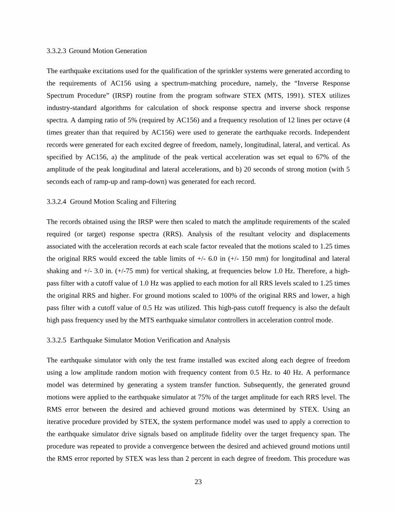
3.3.2.3 Ground Motion Generation
The earthquake excitations used for the qualification of the sprinkler systems were generated according to
the requirements of AC156 using a spectrum-matching procedure, namely, the “Inverse Response
Spectrum Procedure” (IRSP) routine from the program software STEX (MTS, 1991). STEX utilizes
industry-standard algorithms for calculation of shock response spectra and inverse shock response
spectra. A damping ratio of 5% (required by AC156) and a frequency resolution of 12 lines per octave (4
times greater than that required by AC156) were used to generate the earthquake records. Independent
records were generated for each excited degree of freedom, namely, longitudinal, lateral, and vertical. As
specified by AC156, a) the amplitude of the peak vertical acceleration was set equal to 67% of the
amplitude of the peak longitudinal and lateral accelerations, and b) 20 seconds of strong motion (with 5
seconds each of ramp-up and ramp-down) was generated for each record.
3.3.2.4 Ground Motion Scaling and Filtering
The records obtained using the IRSP were then scaled to match the amplitude requirements of the scaled
required (or target) response spectra (RRS). Analysis of the resultant velocity and displacements
associated with the acceleration records at each scale factor revealed that the motions scaled to 1.25 times
the original RRS would exceed the table limits of +/- 6.0 in (+/- 150 mm) for longitudinal and lateral
shaking and +/- 3.0 in. (+/-75 mm) for vertical shaking, at frequencies below 1.0 Hz. Therefore, a high-
pass filter with a cutoff value of 1.0 Hz was applied to each motion for all RRS levels scaled to 1.25 times
the original RRS and higher. For ground motions scaled to 100% of the original RRS and lower, a high
pass filter with a cutoff value of 0.5 Hz was utilized. This high-pass cutoff frequency is also the default
high pass frequency used by the MTS earthquake simulator controllers in acceleration control mode.
3.3.2.5 Earthquake Simulator Motion Verification and Analysis
The earthquake simulator with only the test frame installed was excited along each degree of freedom
using a low amplitude random motion with frequency content from 0.5 Hz. to 40 Hz. A performance
model was determined by generating a system transfer function. Subsequently, the generated ground
motions were applied to the earthquake simulator at 75% of the target amplitude for each RRS level. The
RMS error between the desired and achieved ground motions was determined by STEX. Using an
iterative procedure provided by STEX, the system performance model was used to apply a correction to
the earthquake simulator drive signals based on amplitude fidelity over the target frequency span. The
procedure was repeated to provide a convergence between the desired and achieved ground motions until
the RMS error reported by STEX was less than 2 percent in each degree of freedom. This procedure was
24
repeated for each scale factor and the corrected motions were used as the baseline motions for the testing
of all ceiling systems.
For each installed ceiling and sprinkler system, the table was excited at each scale factor (using the
previously determined motions) and the test response spectrum (TRS) was calculated for each degree of
freedom. For most systems, the excitation levels used were 0.25, 0.50, 0.75, 1.00, 1.25, 1.50, 1.75, 2.00,
2.25 and 2.50 times the original RRS. When the TRS deviated from the RRS by more than 10% during
the course of testing and analysis, the ground motions were corrected using additional STEX iterations as
described earlier. Each system imposed slightly different dynamic characteristics on the earthquake
simulator, requiring minor adjustments to the motions in most cases.
ICC (2004) requires the test response spectrum (TRS) associated with the earthquake histories used for
qualification must envelope the required (or target) response spectrum (RRS) using a maximum-one-
third-octave bandwidth resolution over the frequency range from 1 to 33 Hz, or up to the limits of the
simulator. A damping ratio of 5% and a resolution of 12 lines per octave (4 times greater than that
required by AC156) were used to generate TRS from the achieved earthquake histories.
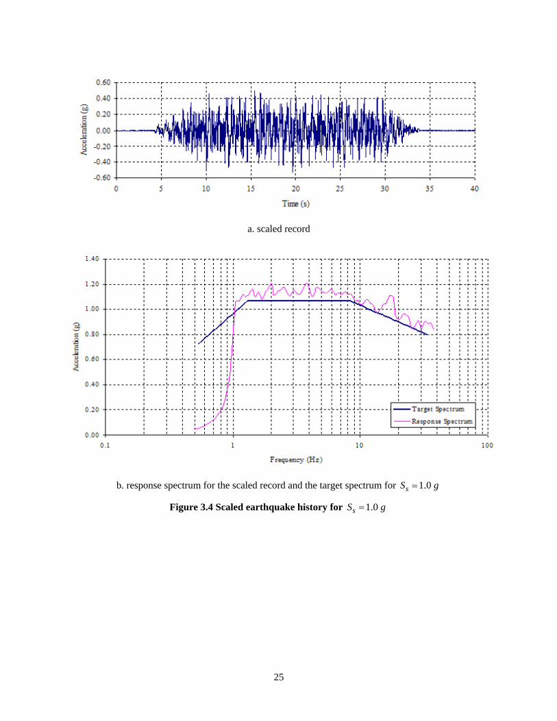
Figure 3.4 shows the earthquake history created after performing the spectrum-matching procedure and
the response spectrum of this record for a target spectrum with 1.0sS g= .
25
a. scaled record
b. response spectrum for the scaled record and the target spectrum for 1.0sS g=
Figure 3.4 Scaled earthquake history for 1.0sS g=
26
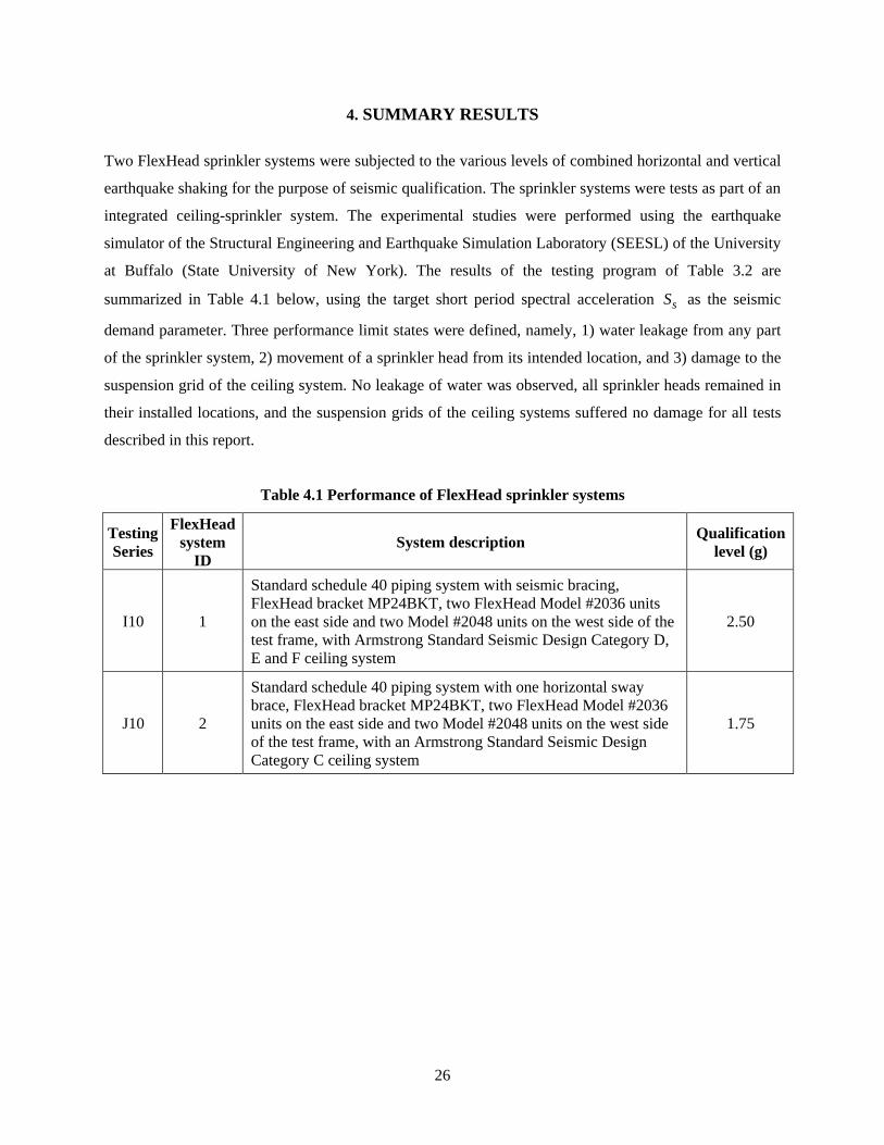
4. SUMMARY RESULTS
Two FlexHead sprinkler systems were subjected to the various levels of combined horizontal and vertical
earthquake shaking for the purpose of seismic qualification. The sprinkler systems were tests as part of an
integrated ceiling-sprinkler system. The experimental studies were performed using the earthquake
simulator of the Structural Engineering and Earthquake Simulation Laboratory (SEESL) of the University
at Buffalo (State University of New York). The results of the testing program of Table 3.2 are
summarized in Table 4.1 below, using the target short period spectral acceleration sS as the seismic
demand parameter. Three performance limit states were defined, namely, 1) water leakage from any part
of the sprinkler system, 2) movement of a sprinkler head from its intended location, and 3) damage to the
suspension grid of the ceiling system. No leakage of water was observed, all sprinkler heads remained in
their installed locations, and the suspension grids of the ceiling systems suffered no damage for all tests
described in this report.
Table 4.1 Performance of FlexHead sprinkler systems
Testing Series
FlexHead system
ID System description Qualification
level (g)
I10 1
Standard schedule 40 piping system with seismic bracing, FlexHead bracket MP24BKT, two FlexHead Model #2036 units on the east side and two Model #2048 units on the west side of the test frame, with Armstrong Standard Seismic Design Category D, E and F ceiling system
2.50
J10 2
Standard schedule 40 piping system with one horizontal sway brace, FlexHead bracket MP24BKT, two FlexHead Model #2036 units on the east side and two Model #2048 units on the west side of the test frame, with an Armstrong Standard Seismic Design Category C ceiling system
1.75
27
REFERENCES
ASTM, 2000. “ASTM C635-00, Standard Specification for the Manufacture, Performance, and Testing of
Metal Suspension Systems for Acoustical Tile and Lay-in Panel Ceilings”, ASTM International, West
Conshohocken, Pennsylvania.
Bachman, R. (2005). Personal Communication.
Badillo, H., Kusumastuti, D., Whittaker A. S., and Reinhorn A. M., 2002. “Seismic Qualification Tests of
Ceiling Systems”, Part I, Report No. UB CSEE/SEESL-2002-01, State University of New York at Buffalo,
Buffalo, New York, April.
Badillo, H., Whittaker, A. S., and Reinhorn, A. M., 2003a. “Seismic Qualification Tests of Ceiling
Systems”, Part III, Report No. UB CSEE/SEESL-2003-01, State University of New York at Buffalo,
Buffalo, New York, February.
Badillo, H., Whittaker, A. S., and Reinhorn, A. M., 2003b. “Seismic Qualification Tests of Ceiling
Systems”, Part IV, Report No. UB CSEE/SEESL-2003-02, State University of New York at Buffalo,
Buffalo, New York, May.
CISCA, 1991a. “Recommendations for Direct-Hung Acoustical Tile and Lay-In Panel Ceilings, Seismic
Zones 0-2”, Ceilings and Interior Systems Construction Association, St. Charles, Illinois.
CISCA, 1991b. “Recommendations for Direct-Hung Acoustical Tile and Lay-In Panel Ceilings, Seismic
Zones 3-4”, Ceilings and Interior Systems Construction Association, St. Charles, Illinois.
Clough, R.W. and Penzien, J., 1993. Dynamics of Structures, 2nd Ed., McGraw-Hill, New York.
Cyr, R., Whittaker, A. S., and Reinhorn, A. M., 2004. “Seismic Qualification Test of Ceiling Systems-A
Study for Armstrong Building Products Operations”, Part VII, Report No. UB CSEE/SEESL-2004-04,
State University of New York at Buffalo, Buffalo, New York, December.
FEMA, 2003. “NEHRP Recommended Provisions for Seismic Regulations for New Buildings and Other
Structures. Part 1-Provisions”, 2000 Ed., Report FEMA 386, Federal Emergency Management Agency,
Washington, D.C.
28
Gulec, C. K., Whittaker, A. S., and Reinhorn, A. M., 2005. “Seismic Qualification Test of Ceiling
Systems-A Study for Armstrong Building Products Operations”, Part VIII, Report No. UB CSEE/SEESL-
2005-01, State University of New York at Buffalo, Buffalo, New York, March.
ICC, 2004. “ICC AC156 Seismic Qualification Testing of Nonstructural Components”, International
Code Council, Country Club Hills, Illinois.
ICC, 2003. International Building Code. 2003 Ed., International Code Council, Falls Church, Virginia.
Kusumastuti, D., Badillo, H., Whittaker A. S., and Reinhorn A. M., 2002. “Seismic Qualification Tests
Of Ceiling Systems”, Part II, Report No. UB CSEE/SEESL-2002-02, State University of New York at
Buffalo, Buffalo, New York, May.
MTS, 1991. “STEX - Seismic Test Execution Software”, MTS Systems Corp., Minnesota.
Repp J. R., Badillo, H., Whittaker, A. S., and Reinhorn, A. M., 2003a. “Seismic Qualification of
Armstrong Suspended Ceiling Systems”, Part V, Report No. UB CSEE/SEESL-2003-03, State University
of New York at Buffalo, Buffalo, New York, September.
Repp J. R., Badillo, H., Whittaker, A. S., and Reinhorn, A. M., 2003b. “Seismic Qualification of
Armstrong Suspended Ceiling Systems”, Part VI, Report No. UB CSEE/SEESL-2003-04, State University
of New York at Buffalo, Buffalo, New York, November.

29