Embed Size (px)
Citation preview

Flexible Conformable Clamps for a Machiniilg Cell with Applications to Turbine Blade Machining
Eiki Kurokaiva
CMU-RI-TR-83-16
Mechanical Enginccring Department and The Robotics Iiistitutc
Carnegie-Mellon University Pittsburgh, Pcnnsyhania 15213
May 1983
Copyright @ 1983 Carnegie-Mellon University
The research culminating in this technical report f o n c d thc author’s blaster's project For the degree of Master of Enginccririg in the Mechanical Engineering Dcpartrncnt at Carncgie-Mcllon University. Sections of this report are adapted from an earlier papcr prescntcd at Autofact IV, Philadelphia, Novcinbcr 1982.

i
Table of Contents 1. Introduction 2. Stcnin 'l*iirbinc Illadc Manufacturing Proccsscs
2.1. A scqucncc of bladc production 2.2. Miichining prcxcss
3.1. A flcxiblc Clamping Systcm 3.2. Clamp Dcsign 3.3. 'l'hc I3ladc-Clamp Asscmbly 3.4. Prc-configuration thc Clamps
4.1. 'Ihcorctical ovcrvicw of Chattcr
3. Clamp Ilcsign
4. Vibration Charactcristics
4.1 .l. A singlc-dcgrcc-of-frccdom vibrating systcm 4.1.2. Systcrns with many Ikgrccs-of-frccdom 4.1.3.13asic thcory of Sclf-cxcitcd Vibration in Mctal Cutting
4.2. tixpcrimcnts and rcsults 5. Conclusion 6. Acknowlcdgcmcnts 7. Appcndix
I 2 2 2 5 5 6 7 9
10 11 11 13 14 17 18 18 19

ii
List of Figures Figure 2-1: Areas to bc rnachincd for a typical turbine blade Figure 2-2: Root Machining in the Cast Fixture Figure 2-3: Stub Machining in the Cradle Fixture Figure 3-1: Blade Clamps Assembly Figure 3-2: Blade Clamps Sctup on the NC Machining Center Figure 3-3: Flexiblc Conformable Clamps - Side View Figure 3-4: Photograph of Thc Flexible Conformable Clamp Figure 4-1: Single degree-of-freedom system Figure 4-2: Diagram of system with many degrees-of freedom Figure 4-3: Basic diagram of chatter Figure 4-4: Basic diagram for the process of self-excited vibi-ation Figure 4-5: Real cross-receptance G and its minimum Figure 7-1: Absolute receptance - from Tlusty Figure 7-2: Real rcceptance - from Tlusty Figure 7-3: Imaginary receptance - from Tlusty Figure 7-4: Phase shift between force and vibration -From Tlusty Figure 7-5: Damped Natural Frequency, New clamps 12" span Figure 7-6: Damped Natural Frequency, New c1,mps 12" span with screw clamps Figure 7-7: Damped Natural Frequency, Cradle type, Haid fixed profile, 12" span Figure 7-5: Damped Natural Frequency, New clamps 16" span
3 4 4 5 6 8 9
11 14 15 15 16 19 13 20 20 21 22 23 24

Abstract
A flcxiblc, conformable clamping schcmc for a steam turbine bladc machining ccll is discusscd. Expcrimcnts that havc bccn carried out to invcstigatc the clamping cffkicncy of this novel dcsign arc also dcscribcd. Flcxiblc fixtures for turbine bladc machining havc bccn dcvclopcd and installcd to dcmonstratc thc reduction of human intcrvcntion for workpiccc setup in the laboratory at Carncgic-Mcllon Univcrsity. I h c kcy fcaturcs of thc clamp dcsign and thc ccll configuration arc dcscribcd. Subscqucntly, thc thcory of vibration is rcvicwcd and thc cxpcrimcntal rcsults of dampcd natural frcqucncics of the clampcd bladc arc prcscntcd. For future rcscarch a ccll modcl may bc cstablishcd and simulatcd. Improvcmcnts in thc clamp rncchanism and an intensive study of vibration arc also expcctcd.

1
1. Introduction ‘I’lic conccpt of tlcsiblc tnachining cclls Iias Ixcti dcscribcd by a numbcr of invcstigators and thc goal is to
protlucc txitchc.; of diffcrcnt parts witlloiit hitinan it~~crvcntion [ l . 2. 3, 41. Although CNC machinc tools. industrial robots and supervisory compii tcrs arc currcntly avni1;tblc and may conibincd to ccmslrcict a flcxiblc mxliining ccll, thc siicccss of a truly flcxiblc machinin_r ccll that runs without human assistirncc dcpcnds on sct.criIl additional dcvclopmcnts of ccll functions such as inspcction, tool sctup, workpiccc sctup. chip rcmoval and tool monitoring. ctc.
Most currcnt flcxihlc mnchining cclls employ pallcts [l. S] to rcducc human assistancc for workpiccc sctirp during a batch run. ldcally human intcrvcntion bctwccn batch runs should bc climinatcd but sincc thcrc arc difticultics involved i n aligning and clamping parts, this is hard to achicvc. With pallcb. t l ~ c fixtiiring bccomcs idcntical ilt cach macliinc tool rcgardlcss of variations in shape and sizc bctwccri diffcrcnt workpicccs. At somc point. howcvcr, parts miisr bc acciiratcly aligncd and clampcd to thc pallcts. In today’s pilpt flcxiblc machining cclls thi5 is done manually but it is desirable to dcvisc an autoniatic clamping system.
In this papcr, flcxiblc conformablc clamps for a stcam turbinc bladc machining ccll arc discussed to cliniinatc human assistancc betwccn botch runs. ’I‘hcrc arc many othcr factors Co prcvcnt thc completion of thc truly unnianncd ccll, howcvcr. wc can approach otic stcp closcr to thc idcal systcm by this attempt.
In a convcntional stcam turbinc bhdc manufacturing piant, tllcrc arc 6000 diffcrcnt bladc designs cach rcquiring diffcrcnt jigs and fixtiircs. ‘I‘liis rcprcscnts an enormous capital invcsrmcnt and providcs a strong motivniion for dcvising a flcxiblc machining ccll. ‘I‘hc bladcs arrive at CNC machining ccntcrs as closed-dic forsings. ‘Ihcs,~ tapcr-twisted shapes arc aiffcult to clamp without spccially dcsigncd jigs and fixtures. ‘Ilic important rolcs of thc clamping arc rapid fixturing, stiffncss against cutting forccs, good vibration charactcristics and holding accuracy. In thc mnnufkturing scqucncc at prcscnt’ , a low niclting point alloy, cerulin, is cast around thc airfoil of thc bladc to provide cffkicnt and scciirc clamping (Fig.2-2). ‘1‘0 machitic out rlirbs (Fig.2-1) ncar thc ccntcr. of thc bladc span, a spccial cradle fixture is irscd to climinatc chatter (Fig.2-3).
’I’hcrc arc a numbcr of reasons for moving away from this systcm involbing thc casting of ccrubin around thc turbinc bladcs 2nd hcavy cradle typc fixturcs. ‘Ihc ccnibin is vcry cxpcnsivc and labor involved in accura?:cly fixing thc blade and then pouring thc alloy around thc bladc is cxpcnsivc. At thc cnd of thc pruccss. thc al!oy must idso bc rcmcltcd and rctrictcd. I n addition, thc bladc bith cast or cradle fixture is too henvy to bc handled by a currcnt industrial robot.
I n ordcr to maintain flcxibility of clamping and climinatc the nccd for thc casting proccss a programmnblc. conformablc clamp has bccn dcvclopcd [6].
’as cirricd out in a Wcstinghousc Elcctric Co. plant at Winston-Salcm N.C.
2
2. Steam Turbine Blade Manufacturing Processes
operation is briefly examined. I n order to get a better understailding of tlie machining proccss during a blade production sequcncc, cach
2.1. A sequence of blade production
There are several possible ways to produce steam turbine blades. A typical sequence introduced in an actual manufacturing plant is listed. This procedure is used to produce large taper-twisted turbine rotor blades for electric power generation. Simpler shaped blades are machined from extruded bar stock and more complicated blades such as gas turbine blades, are made by casting. However, the sequence below is typical for thc mid-range of complexity such as steam turbine blades.
1. Raw material - Cylindrical billet
2. open die forsing - swaging2
3. Closed precision die forging
4. Trimming
5. Heat trcatment
6. Inspection - Hardness and Dimension
7. Remedy distortion by press and repeat inspection
9. Grinding - Airfoil surface
10. Inspection - Dimension, Weight and Vibration
2.2. Machining process
The machining process is examined in detail to design an appropriate fixture. Fig.2-1 shows each area to be machined corresponding to the following list. Typical.milling conditions are also listed in accordancc with Machining Data Handbook [7] for a solution heat trcated precipitation hardening stainless steel of Brinell hardness 275 - 325. [d = depth of cut, v = speed, f = feed per tooth]
1. Root (Fig.2-2)
a. Bottom surface milling - Face cutter [d = 4 mm, v = 105 m/min, f = 0.18 mm]
b. Rough milling - Tapered sidc cutter [d = 4 mm, v = 70 m/inin, f = 0.13 mm]
'A Flexible Swagins Cell has been dcvclopcd and installed at the Turbine Components Plant Wcslinghousc Electric Co. h'C. [4]

3
c. Prc-finish milling - Formed cutter [d = 4 mm, v = 14 m/min, f = 0.15 mm]
d. Finish milling - Formed cutter [d = 0.2 mm, v = 50 m/min, f = 0.15 mm]
2. Sides of Root (Width) - Face cutter [d = 4 mm, v = 105 m/min, f = 0.18 mm]
3. Side edges - End mill cutter [d = 1.5 mm, v = 64 m/min, f = 0.15 mm]
4. Tip of blade
a. Tip edge - Face cutter [d = 4 mm, v = 105 m/min, f = 0.18 m]
b. Tenon - End mill cutter [d = 1.5 mm, v = 64 m/min, f = 0.15 mm]
5. Stub (Fig.2-3)
a. Face - Face cutter [d = 4 mm, v = 105 m/min, f = 0.18 m]
b. Contour - Ball end mill cutter [v = 64 m/min, f = 0.15 mm]
6. Stellite brazing groove - End mill cutter [d = 3 mm, v = 14 m/min, f = 0.05 mm]
7. Locking piece hole - End mill cutter [v = 14 m/min, f = 0.05 m]
Figure 2-1: Areas to be machined for a typical turbine blade

. Figure 2-2: Root Machining in the Cast Fixture

. Figure 2-2: Root Machining in the Cast Fixture

5
3. Clamp Design
3.1. A flexible Clamping System I n kccping witti thc abovc considcrations a flcxiblc clamping systcm has bccn dcviscd for a machining ccll
in thc author's laboratory (Figs.3-1.3-2). 'I'hc design is ablc to copc with thc conlplcx thrcc dimcnsionnl form of thc bladcs and thc abscncc of obvious oricntational fcaturcs such as holcs or square cdgcs. Additional rcquircmcnts for a succcssfiil clamping systcm may bc listed as follows:
0 'I'hc cli1mps should bc light and compact cnough to travel with thc bladc so that thc proccss of' ahgnincnt nccd bc donc only oncc.
'I'hc clnnips should handle as many as possiblc of thc diffcrcnt bladc stylcs.
0 'I'hc clamping should bc rigid cnough against cutting forcc and havc good vibration charactcristics to prcvcnt chattcr.
0 'I'hc clamps should facilitate automatic clamping and unclamping.
Blade Clamp Assembly
SECT!ON A-A Figure 3-1: Dladc Clamps Asscnibly

6
Figurc 3-2: I3ladc Clamps Sctiip on thc NC Machining Ccntcr
3.2. Clamp Design
'Ihc clamp design shown in Figs.3-3,3-4 climinatcs thc shortcomings of thc clamps bcing uscd at prcscnt but retains thc adapt3bility of thc cast alloy clamp systcm. 'I'hc clamps consist of octagonal frilmcs that arc hingcd so that thcy may bc opcncd to acccpt a bladc and thcn closed. Thc clamps rnay bc plxcd alrnost anywhcrc along thc ttirbinc bladc. Usually two or thrcc clamps will hold thc bladc rigidly. Using octagonal shapcs rathcr than a squarc alfows thc bladc-clamp asscmbly to assumc morc oricntations about thc bladc's longitudinal axis. Sincc thc bladc cross scctions twist substantially from onc cnd of thc bliidc to thc othcr h i s is a ncccssary fcaturc to obtain an appropriatc clamping anglc bctwccn a bladc and plungcrs (Fig.3-2).
'I'hc lowcr half of cach clamp crnploys plates or plungcrs that, whcn rclcascd. arc frcc to conform to thc profilc of thc turbinc bladc. A similar tcchniquc has bccn iiscd for progamnwblc powdcr rnctal dics and for shcct mctnl forming. 18.91 A high strength bclt is wrapped ovcr thc convcx surf. x c of thc hladc and is iiscd to
hold thc bladc against thc plungcrs in thc lowcr halfof thc clamp. 'Ihc plungcrs arc forccd as;iinst thc turbinc bladc wing air prcssurc. Oncc a profilc has bccn sct, Ihc plungcrs arc mcchanically lockcd in placc and thcn air supply rnay bc disconncctcd. 'rhc bclt is thcn tightcncd and thc clamps arc frcc to trawl with thc bladc. If thc position of a clamp must bc changcd during the machining proccss it is possiblc to allow a ncw clamp to conform to thc blade in a ncw location arid then to rcniovc thc clamp from thc old location so that the oricntation of thc turbinc bladc is ncvcr lost.

7
To experirncnt with differcnt plate sliapcs and sealing materials of the air chamber in the lower half, a small box containing just a dozen stecl plungers was first constructcd. In the original design, every other steel plate was alternated with a teflon plate. The purpose of the teflon plates was to allow tile steel plates to slide freely and to embed any small particle that might gall or scratch the steel plates. Because of the soft and elastic nature of the thick teflon plates ( 1/16 of a inch ), the teflon plates have been abandoned in favor of coating the steel platcs with a thin (0.001 of a inch) film of teflon to improve the dimensional accuracy and stability of the clamps. Tests with different scaling materials have shown that loss of air, while the clamps are connected to an air supply, can be kcpt low. The required air pressure is about 40 psi.
A number of mechanisms for locking the plungers, for locking upper and lower frames and for tightening the high strength friction bclt have been investigated. The plungers are locked by a series of set screws with locking pieces inside the air chamber. For locking the upper and lower frames, a toggle type clamp is devised and placed at the other end of the hinge pin. The toggle clamp is easy for a robot to operate by one touch action whereas a bolt-and-thread type mechanism amounts to an assembly task for a robot. The belt is reinforced by Kevla? cables and is tightened or released by a sliding block moved by a driving screw. Although Kevlar cables are strong, they are not resistant to abrasion. Alternatively, swivel screw clamps may be used instead of the belt for cases in which the edge of a workpiece is very shad. These incchanisms must be compact, simple and easy to operate automatically. The last requirement is tl!e most difficult to satisfy. In the development so far, a series of set screws and the belt tightening screw may be driven by an air tool held by a small 3 axis robot installed at the clamping station in the cell.
3.3. The Blade-Clamp Assembly
Once two or three clamps have been fastened to a turbine blade, the blade-clamp assembly becomes a pallet in the form of an octagonal prism. The outer dimensions of the assembly are well defined and do not vary from part to part. A single fixturing arrangement can be used on all the machine tools in the cell. Furthermore, there is no need to modify the fixturing when the cell changes between blade styles. Figure3-1 shows a blade held by two clamps which are mounted on a fixturing plate. Standard hydraulic hold-down clamps are used to fix the assembly in place while it is machined.
The robot which transports the blade-clamp assembly also benefits From a standard octagona: shape. The robot does not nced to hold the assembly as rigidly as the machine tools, just firmly enough to keep the assembly from slipping while it is being transported. The robot can thcrefore use a simple gripping arrangement.
'Kevlar is a rcgistcrcd tradcmark of Du Pont

8
Figure 3-3: Flcxiblc Conformable Cla1:lps - Side Vicw
o n
0
Y
u ic
P- P
....

9
Figure 3-4: Photograph of The Flexible Conformable Clamp
3.4. Pre-configuration the Clamps The discussion thus far has focused on the conformable nature of the clamps. Once a turbine blade is
brought into alignmcnt the clamps will conform to its profile. At other times, when starting a new batch of blades for example, it is desirable to have the clamps pre-configured to the correct profile for the new part. To give them this profile the use a "master profile" has bcen proposed [6]. Thc master profile would consist of plates or plungcrs that are automatically driven to a desircd position usin:, stepping motors. The desired profile would be specified by a computer which would rely upon a database containing the geomctrical rcpresentation of the turbine bladc. The individual conformable clamps would then be held against this master profile and adopt to its shape. Since the master profile would not travel with the parts it would not have to be compact or lightweight. The process of adjusting the mastcr profile would not have to be a rapid onc since it would not occur on line. While the ccll was busy machining blades from a current batch, the master profile would be adjusted and additional clamps would be held against it to prepare them for the new part shape.

10
4. Vibration Characteristics Altliougli tlic iiiain objcctivc of this rcsciirch is to dcvclop a clainping systcni for an iiiininiiiicd flcxihlc
machining ccll. it is ills0 iiiiportiiiit to undcrstnnd tlic vibration cliarnctcristics of tlic dcsigiicd clilIiil> with a bladc during mctnl cutting opcration.
In thc practical turbinc bladc machining proccss largc vibrations arc oftcn cncountcrcd. 'I'hcsc givc risc to undulations on tlic machincd SurfiIcc ajid cxccssivc variations of thc cutting forcc which cndangcr tlic lirc of thc tool and of thc machine. 'Ilicrcforc cutting conditions arc choscn lowcr than tlic dcsircd Vil luC and additional pads or fixtures arc applicd to incrcasc stiffncss (Fig.2-2).
As a rcsult of thc various kinds of forccs which occur during thc machining opcration, various spccifications of rcquircincnts on stiffness may bc statcd within thc following thrcc catcgorics.
1. Ilcformations causcd by cutting forccs
2. Vibrations cxcitcd by cutting forccs
3. Sclf-cxcitcd vibrations - Chatter
(1): Iluring thc cutting opcration thc cuttin forcc varics and its nint of application movcs. In conscqucncc, thc dcforniation of thc workpiccc and/or thc framc of thc machine will vary. causing clcviations of thc fomi of the machincd surfaccs. 'I'his cffcct niay bc limited by dccrcasirig thc cutting conditions and conscqucntly the output of thc opcration. In this particular bladc machining proccss, it is assiimcd that tlic lcast stiff component of thc systcm tool-machinc-workpiccc is tllc bladc, sincc wc usually choosc a machinc tool having a suffcicntly rigid spindle. 'I'licn Ihc important fcaturc is to know thc dynaniic stiffness of tlic bladc-clamp systcni. In gcncral. cxpcricncc shows that oncc a cutting condition without cliattcr is satisficd, dcformations causcd by cutting forccs arc also within thc dcsircd valuc [lo].
(2): Forccd vibrations arc now considcrcd. 'Iliis problcm was studied by 'I'lusty [lo) ctc. to analy7.c thc vibration charactcristics of machine tool structures. Thc kcy fcatiirc to prcvcnt vibrations cxcitcd by rlie cutting forcc is to choosc cutting spccd that do not coincide with thc natural frcqucncy uf tlic systcm tool- machinc-workpiccc. I f cutting spccds in thc rangc 200 - 700 ft/min uscd for carbide ciittcrs whcn rnilliiig stccl and cuttcrs with a compilrativcly fine pitch of 2 inclics arc assunicd. thc tooth frcqiicncy will bc in thc rangc 20 - 70 HI. In gcncrnl. thc significant rnodcs of rclativc vibration bctwccn tool and workpiccc in milling machincs liavc natural frcqucncics in tlic rangc 1% - 300 1 1 ~ . 'I'hcrcforc. thc basic harmonic ccjniponcnt of thc
cutting forcc acts far from rcsonmcc with thc significant rnodcs of thc m m i r c . 7hc particular rcsults for this turbinc bladc machining arc discusscd in thc latcr scction.
(3): Sclf-cxcitcd vibration - Chatter is discussed dctai: in thc following subscction.
11
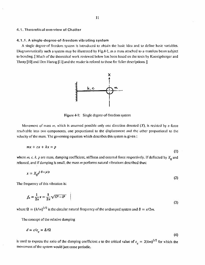
4.1. Theoretical overview of Chatter
4.1 .l. A single-degree-of-freedom vibrating system
A singlc dcgrcc-of frccdorn systcin is introduccd to obtain thc basic idca and to dcfiiic basic variablcs. l~iagrammatically such a systcm may bc illcrstratcd b y Fig.4-1. as a mass attnclicd 10 a niasslcss b c m subjcct to bcnding. [ Much of thc thcorctical work rcvicwcd bclow has bccn bascd on thc tcxts by Kocnigsbcrgcr and ‘I’lusty [IO] and Ilcn Hartog [I 11 and thc rcadcr is rcfcrcd to thcsc for fiillcr dcscriptions. J
X t
Figure 4- 1: Singlc dcgrcc-of-frccdorn systcrn
klovcmcnt of mass I)?, which is assumcd possiblc only onc dircction dcnotcd (A‘), is rcsistcd by a forcc rcsolvablc into two componcnts, onc proportional to thc displaccincnt and rhc othcr proportional to thc
vclocity of thc mass. ‘I’hc govcrning cquation which dcscribcs this systcrn is givcn :
mx + cx + kx = p (1)
whcrc in, c. k. p arc mass, damping cocfficicnt. stiffncss and cxtcrnal forcc rcspcctiucly. If dcflcctcd by ,Yo and rclcascd, and if damping is small, thc mass i n pcrforms natural vibrations dcscribcd thus:
‘I’hc frcqucncy of this vibration is:
whcrc $2 = ( k / , r ~ ) ” ~ is the circular natural frcqucncy of thc iindampcd systcm and 6 = c/2m.
I h c conccpt of thc rclativc damping
d = c/cc = 6Al (4)
is uscd to exprcss thc ratio of thc damping cocfficicnt c to thc critical valuc of cc = 2(kn1)’ /~ for which the movcmcnt of thc systcm would just ccasc periodic.

12
If an input force p = Pe""acts on thc mass in the direction (X), the system perfomis steady vibrations:
x = X d u f whcrc X = A&'.
The amplitiide of the output vibration is A and the phase shift between the applicd force and tlic resulting displacement is cp, both these quantities being implicit in the factor X. Substituting x and p into tlte equation (l), X for hamionic excitation with frequency o is obtained.
( 5 ) The function @(w) is called the receptuiice or dynamic compliance (inverse of dynamic stiffness) of the system. Its absolute value F(u) is expressed in Fig.7-1 in units of l/k, for various values of d. The real part of a, as a hnction of a, is expressed by:
The imaginary part of iP is given by:
The phase shift cp of X with respect to P i s given by:
H 2bo 1 tan 9 = - = -- G ,rl?-o* 1 (8)
Exprcssions (6). (7) are callcd real and imaginary receptance respectively. The real receptance, the imaginarjr receptance and the phase shift are indicated in Figs. 7-2,7-3,7-4.
Significant points of the receptance curves appear at the following values of the frequency of tlie exciting force:
1. w = Q , phasc shift is exactly 'p = -n/2.
2. 0 = Q.d1-2$ , or approximately w = Q(1 -d2) miximum of the absolute reccptance, Fma.
3.w=R1/1-d"-= v (frequcncy of natural vibrations of thc system) no spccial significance for response curves.
I 4. w = ~43, or approximately w = Q(I 26)

13
maximum and minimum points of the real rcccptancc GmmX
1 1 I
minimum of the imaginary response Hmin = - 1/2dk.
If a real reccptance curve is given the damping ratio dis calculated by:
a m i n - a m a x
I
where amin and am are frequencies at which G attains its minimum and maximum respectively. (9)
4.1.2. Systems with many Degrees-of-freedom
For the general case, systems with many masses, located quite generally in three-dimcnsional space, parlly interconnected with many springs, may be assumed. A two-dimensional diagrammatical representation of one such system is shown in Fig.4-2. This system may have many natural frequencies, SI,, damping factors Si and corresponding modal shapes. To every modal shape there corresponds a particular direction (,?) in which a particular point, say Q, of the system vibrates in the given mode. If a variable excitation force p = Pdor acts on one point Q of the system, and if a particular direction (Y) is chosen, the angle between (Y) and P being p and the angles between (Y) and individual modal directions (Xi) being ai, then vibration of the point Q in the direction (Y) will be:
where
The "directional factors ui " are :
ui = cosaicos(ai - 8)
and ki are stiffnesses corresponding to the individual modes and to thc chosen point a in the systcm, For the case in which the individual modes would be cxcitcd by a harmonic force acting on point c1 in the directions (Xi, of the individual modes rcspcctivcly. F.quation (10) may be written using F, Gand H, as:

14
where
i I
Figure 4-2: Diagram of system with many degrees-of freedom
ton1
Ll', Y = PZuiGi + juiHi = P(G + jH) = fW
where Gi and Hi arc of the forms by eqs. (6) and (7) respcctively.
It is to be understood that the partial real and imaginary responses Gi and Hi of the individual modes correspond to cases where the individual modes would be excited in their corrcsponding directions (Xi>. They are direct-receptances. Functions a, G and H are called crossreceplances.
The system tool-workpicce-machine has infinite number of degrees- of-frcedom. The higher the natural frequency of the mode, the higher the value of its stiffness and also the value of damping'is usually higlicr in higher modes. Therefore, the higher the mode the smaller is its participation in the resulting vibration. It follows that for practical significance of metal cutting vibration all but several lower modes ofthe system ran be neglected.
4.1.3. Basic theory of Self-excited Vibration in Metal Cutting The basic diagram of the process of self-cxcited vibration in metal cutting .is presented schematically in
Fig.4-3. It is a closed loop system including two hndamental parts, the cutting process and the vibratory system of the machine. It indicates that die vibration Y between tool and workpiccc influemcs the cutting proccss so as to cause a variation P of the cutting force which, actiag on the vibratory system of thc machine, creates again vibration Y.
The relationship cxpresscd in Fig.4-3 is written thus:
P = - R Y or P = - b r Y

15
2 Vibrating System 9 7 t 2 Figure 4-3: Basic diagram of chatter
The coefficient R expresses the intensity of the coupling between vibration and cuting force, or the "gain" in this part of the loop. The coefficient b is the chip width and r is a coefficient, depending on all othcr cutting conditions (b, r are real positive). I f the amplitude of vibration in ,the direction of the normal to the cut surface in the i th cut was Yo and in the (i + 1)th cut it is Y, then the amplitude of chip thickncss variation is ( Y : YJ. This model is shown in Fig.4-4.Consequently, instead of eq.(14), eq.(15) must be used for actual metal cutting operation:
P = - bt(Y- Y$
Figure 4-4: Basic
I L,,,,- - - --I
diagram for the process of self-excited vibration
Quations (12) and (15) can be combined into
and, after modification

16
Equation (17) dcscribcs the closed-loop systcm of sclf-cxcited vibrations. I f the amplitude Y of vibrations in a cut is largcr than thc amplitude Yo of vibrations in the preceding cut, the system will be unstable. The condition for thc limit of stability can bc expressed as:
which signifies that Y will be equal to Yo. Equation (18) will be transcribed according to (12) to
Since values b and r are.rea1 positive, the value of l /b r is rcal and positive. Thus the vectors in the numerator and in the denominator of q in eq.(19) have the same ima@nary panjH. Equation (19) requires that the moduli of the vectors in the numerator and in the denominator of 4 be equal. Then the absolute values of the real parts of both vectors are equal.
I
I 14'1 =
Condition (20) can be satisficd only if:
l / b r + G = - G or 1/2brh = - G(wlim)
I
I-
Figure 4-5: Real cross-receptance Gand its minimum
Equation of (21) is the form of the ccndition for the limit of stability. If the rcal rcceptance curve G(o) was given and r was constant, thc maximum chip width btim for which cutting can be stable, is obtaincd as Fig.4-5. Assuming the larger chip width (the valuc of - 1/2br is larger than point B). the chattcr could occur at any poinm bctwcen D and E.

17
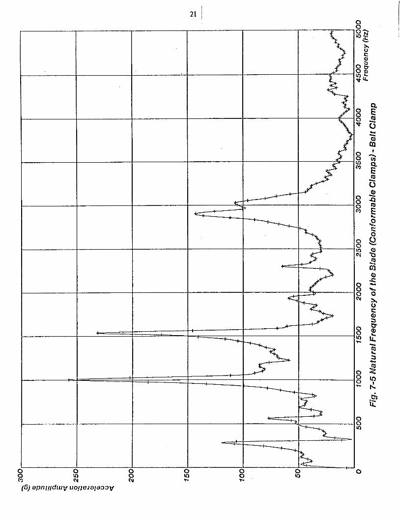
4.2. Experiments a n d resu l t s 'I'lic aim o f tlic cspcriincnts carried out so far wilS to find thc dalripcd ni~t~ i r i l l frcqucncics o f thc clampcd
turbinc blndc. A piczoclcctric accc1cro1nctcr was mountcd on thc bladc and ;in impulsc input was givcn by "impulsc rcsponsc tcsting" (a sharp harnincr blow). 'I'hc load ccll which was mounted on thc hammcr triggrcd thc incmirctncnt of tlic output rcsponsc from thc turbinc bladc. 'I'hc output wavcforms in thc time domciin wcrc nlci1slircd and rccordcd by a Nicolct Iligiul Oscilloscopc which was cquippcd with an I/O intcrfacc with a floppy disk drivc dcvicc. 'I'hc stored rcsponsc wavcfoims wcrc directly transfcrrcd to the VAX 111750 computcr of thc Mcchanical I-hginccring Ikpartmcnt and analyzcd by thc Fast I h r i c r 'I'ransformation (1 - I -T ) method to find thc primary pcak of thc accclcration amplitudc in thc frcqucncy domain. 'I'hc frcqucncy value at thc priinary pcak is significant bccausc it rcprcscnts thc danipcd natural frcqucncy of thc clampcd bladc system. 'I'hc valuc of accclcration amplitudc is significant only in each individual cxpcrimcnt bccausc an impulsc input is givcn by a manual hammer blow and thc resultant accclcration amplitude is not nonnalizcd by an irnpulsc input.
A bladc of 22 inchcs Icngth was sct up on thc two conformablc clamps 12 inchcs apart. 'Ihc whulc blade-clamps assembly was thcn sct on thc work tablc of a llrnwn 8( Sharpc vcrtical spindle CNC machining ccntcr (Fig.3-2). 'I'hc vibration amplitudes wcrc mcasurcd for both bclt clamps and swivcl scrcw clamps. 'I'hc vibration was also mcasurcd for thc same bladc in thc cradle type fixturc with rigid fixcd clamps (Fig.2-3) of 12 inchcs clamping span and tlic rcsults wcrc comparcd with thc ncw conformablc clamps cascs.
'I'hc rc:;ults arc shown i n Fig.7-5, Fig.7-6 and Fig.7-7 as frcqucncy vcrsus accclcration amplitude plots. I n thc cradlc type fixturc with rigid clamp forms (Fig.7-7) a very sharp pcak of thc accclcration amplitudc is obscrvcd at 490 CIz. and thrcc othcr minor pcaks of lcss than onc third of the primary amp!itudc arc obscrvcd at 320 tiy. . 1530 Hz and 2670 Hz. On thc othcr hand, in thc ncw conformablc clamps (Fig.7-5) thc primary pcak is obtaincd at 1000 Hz and minor pcaks arc obscrvcd at 250 Hz, 1540 Hir. and 2900 Hz. In comparison with thc abovc two rcsults, thc primary sharp pcak at 490 Hz in tlic cradlc fixturc has disappcarcd in thc ncwly dcvclopcd conformablc clamps. This fact illustratcs anothcr advantage of thc iicw conformablc clamps ovcr thc heavy cradle fixtiirc. For thc casc of using swivel scrcws instcad of bclts Fig. 7-6. thc primary pcnk is at 1590 H z and thc sccondary pcak is at 610 Mz. The primary peak at 490 t l z has also disappcarcd in this case.
Considering thc typical machining conditions shown in section 2.2, frcqucncics of cxtcrnal cutting forccs applicd to thc bladc arc thc rangc from 5 Hz (prc-finish milling of thc root) to 200 H z (contcur milling at tlic root of thc stub). I f a roughing cnd mill cutter wcrc uscd a higher frcqucncy could easily attained. For cxarnplc a roughing cnd mill of 2 millimctcrs tooth pitch was sclcctcd for sidc cdgc milling and cutting spced \vas set as 64 ni/min. thc frcqucncy of this cutting forcc is 533 HI,. 'I'hcrc is a possibility that thc frcqucncy of thc cxtcrnal cutting forcc could coincide with thc natural frcqucncy of thc clampcd bladc in thc cradlc fixturc with rigid clamp forms. Wc may conclude that thc cradle typc fixturc is not appropriatc for this opcration.
In thc cxpcrimcnts dcscribcd so far, thc clamping span was choscn to bc 12 inchcs in ordcr to comparc the natural frcqucncy of tlic conformablc clamps with that of thc cradle type rigid fixcd clamps. For the

18
coiiforiiiablc clamps. clamping positions CiIII bc easily cliangcd to the dcsircd Span. '1'0 dcrT1onstratc thc effect of changing tlic clatnping span a span of 16 itichcs was tcstcd. 'I'hc result is shown in Fig.7-8. I t1 this CiISC. thc
primary peak is obscrvcd at 245 t-17. which is lower than tlic 12 inches span casc as cxpcctcd.
5. Conclusion This rcscnrch is conccrncd with tlic dcvclopmcnt of flcxiblc confoniiablc clamps for a stcnm turbinc bladc
machining ccll. Thc design prcscntcd hcrc has thc flexibility to conform various complcx shapcs of workpicccs by introducing plungcrs and high strcngtli belts. Additional oricntational flexibility is providcd by the octagonal shapc of thc clamps. l'hcsc flcxibilitics, togcthcr with light-weight design of tlic clamps. niakc it possible to construct an unmanncd workpiccc sctirp station. A number of intcrcsting possibilitics arc occur at this point. For cxamplc. thc sctup station can bc combincd with an inspection station. A non-contact mcasuring dcvicc mountcd on a precision industrial robot could scrvc for this purpose.
'I'hc turbinc bladc dampcd by thc conformablc clamps has good cliaractcristics for forced-exci/ed vibrations. 'I'hc basic harmonic componcnt' of thc cutting forcc acts far from rcsonancc. In fiiturc rcscarch, thc modal analysis and displaccmcnt mcasurcrncnts wit1 bc rcpcatcd in ordcr to find thc pcrformnncc against self excircrl vibrations (cha ttcr).
6. Acknowledgements This rcscarch was conducted undcr thc direction of Profcssor Paul K. Wright of thc Mcclianical
Engineering Ilcpartmcnt, Carncgic-Mcllon Univcrsity. Thc original concept of thc clamp design was skctchcd out by 1Mr. Mark R. Cutkosky and thc dcvclopmcnt procccdcd with his discussion. Thc author thanks Mr. Robert Milligan Jr. for his providing FFI' programs for tlic vibration analysis work. I'hc author also thanks Mr. J. K. Dillingcr and Mr. 11. T. McKccl for thcir advicc and assisancc in producing thc clamps. 'I'hc rcscarch en\ ironmcnt was providcd by Wcstinghousc Elcctric Corporation. 'I'hc iiuthor's cducational opportunity Has givcn by Mitsubishi Hcavy Industrics, I.td.

19
7. Appendix
Figurc 7-1: Absolute receptance - from Tlusty
I
I
i I !
I
Figurc 7-2: Real reccptance - from Tlusty

20
Figure 7-3: Imaginary receptance - from Tlusty
Figure 7-4: Phase shift bctween force and vibration -from Tlusty
*l I
e
d
0 0 v-
I
Y
f
IC
0 0 0 P
0 0 u) M
0 0 0 n
0 0 10
0 0 0 N
0 0 Ir) h
0 0 0 ?-
0 0 0
0

8 0 v
8 u) m
0 0 0 m
0 0 0 N
8 0 N
8 0 T-
O 0 0 h
0 0 0
3

23 '
8 0 9
0 0 10 rn
0 0 0 9
Q 0 10 nr
0 0 8
8 v) h
0 0 0 - 0 0 10
0


25 '
h F I
1

__ ---
’ , c
26
_-

i

28
1.
2.
3.
4.
5.
6.
7.
8.
9.
10.
11.
References
Bjorke,O., “Computer-Aidcd Part Manufacturing,” Conzyurcrs in Industry, Vol. 1, January 1979, pp. 3-9.
Merchant, M.E., “The Computer integratcd Factory,” ASME Publication PED-I, Towards The Factory of The Future 1981, . Weck,M., Zenner,K., and Tuchelman,Y., “New Developments of Data Processing in Computer Controlled Manufacturing Systems,” Sociefy of Man2facturing Engineers Technical Paper, No. MS79-161,1979,.
WrighfP.K., Bourne,D.A., Colycr,J.P., Schatz,G.C. and Isasi,J.A.E., “A Flexible Manufacturing Celt for Swaging,” The 14th CIRP Seminar on Flexible Manufacturing Systems, June 1982, , Trondheim, Norway
Groover,M.P., Autotnafioii Production Systenis and Computer Aided Mantlfacturing, Prenticc-Hall Inc., Englewood Cliffs, NJ, 1980.
Cutkosky,M.R., Kurokawa,E. and ’ Wright,P.K., “Programmable Conformable Clamps,” AUTOFACT4 Conference Proceedings, November 1982, pp. 11.51-11.58, Society of Manufacturing Engineers, Dcarborn, MI
Metcut Research Associates Inc., Machining Dafa Hatidbook. Metcut Research Associate Inc., 3980 Rosslyn Ilrivc Cincinnati, Ohio 45209,1980.
\.VrighfP.K., Holzer, A.J., “A Programmable Die for the Powder Metallugy Process,” 9th hrorlh .4mericmi hfmufacturing Research Confermce at State Cdlege PA (NAMRC IX), May 1981, pp. 65-70.
Cossard,D.C., Hardt,D.E., McClintock,F.A., Allison,B.T., Gu,i. and Stelson, K., “Discrete Die Surface For Sheet Metal Parts,” ICAM End of Corilract Briefings, Wrighl-Pallerson AFB, January 1980, . Koenigsberger, F. and Tlusty, J., hlachine Tool Structures, Pergamon Press, , Vol. 1, 1970.
Hartog. J.P. Den, Mechanics[ Vibrations, McGraw-Hi11 Book Company, 1968.


![Flexible Conformable Clamps for a Machining Cell with ...€¦ · Contour - Ball end mill cutter [v = 64 m/min, f = 0.15 mm] 6. ... 'I'hc lowcr half of cach clamp crnploys plates](https://img.pdfslide.net/doc/110x75/5eb5a2a3059ac3309c2b1546/flexible-conformable-clamps-for-a-machining-cell-with-contour-ball-end-mill.jpg)