Embed Size (px)
Citation preview

Flexible-Membrane Airfoils at Low Reynolds Numbers
Hui Hu,∗Masatoshi Tamai,† and Jeffery T. Murphy†
Iowa State University, Ames, Iowa 50011
DOI: 10.2514/1.36438
An experimental study was conducted to assess the benefits of using flexible-membrane airfoils/wings at low
Reynolds numbers for micro air vehicle applications compared with using a conventional rigid airfoil/wing. In
addition to measuring aerodynamic forces acting on flexible-membrane airfoils/wings, a high-resolution particle
image velocimetry system was used to conduct flowfield measurements to quantify the transient behavior of vortex
and turbulent flow structures around the flexible-membrane airfoils/wings to elucidate the associated underlying
fundamental physics. The aerodynamic force measurements revealed that flexible-membrane airfoils could provide
better aerodynamic performance comparedwith their rigid counterpart at lowReynolds numbers. Theflexibility (or
rigidity) of the membrane skins of the airfoils was found to greatly affect their aerodynamic performance. Particle
image velocimetry measurements elucidated that flexible-membrane airfoils could change their camber (i.e., cross-
sectional shape) automatically to adapt incoming flows to balance the pressure differences on the upper and lower
surfaces of the airfoils, therefore suppressing flow separation on the airfoil upper surfaces. Meanwhile, deformation
of the flexible-membrane skins was found to cause significant airfoil trailing-edge deflection (i.e., lift the airfoil
trailing edge up from its original designed position), which resulted in a reduction of the effective angles of attack of
the flexible-membrane airfoils, thereby delaying airfoil stall at high angles of attack. The nonuniform spanwise
deformation of the flexible-membrane skins of the flexible-membrane airfoils was found to significantly affect the
characteristics of vortex and turbulent flow structures around the flexible-membrane airfoils.
Nomenclature
C = chord length of the airfoilCl, Cd = lift-and-drag coefficientsN = total number of frames of the instantaneous PIV
measurementsReC = chord Reynolds numberU = mean velocity components in the x direction,
�Ni�1ui=N
ui, vi = instantaneous velocity components in the x and ydirections
V = mean velocity components in the y direction,�N
i�1vi=NV1 = incoming flow velocityx, y = Cartesian coordinate directions!z = spanwise vorticity, �@vi=@x� � �@ui=@y�
Introduction
M ICRO air vehicles (MAVs), which are characterized by smallvehicle size (approximately 10 cm) and low flight speeds
(approximately 10 m=s), are of great interest to both military andcivilian applications. Equipped with video cameras, transmitters, orsensors, these miniaturized aerial vehicles can perform surveillance,reconnaissance, targeting, or biochemical sensing tasks at remote,hazardous, or dangerous locations. Research progress made in recentyears has resulted in advances in miniaturized digital electronics,microfabrication, miniaturized power cells, remote communication,imaging and control devices, and other enabling technologies. Suchadvances have turned the concept of MAVs as rapidly deployableeyes-in-the-sky from fiction into demonstrated fact. The continuing
demand for such small and robust miniaturized aerial vehicles ismaking MAVs an emerging sector of the aerospace market.Although a number of MAVs, either in fixed-wing or flapping-
wing designs, have already been developed by universities andcommercial- and government-funded endeavors, the airfoil andwingplanform designs for many existing MAVs rely mainly on scaled-down reproductions of those used by conventional macroscaleaircraft. Chord Reynolds number ReC, which is based on airfoilchord length and flight velocity, is usually used to characterize theaerodynamic performance of an airfoil/wing. Although traditionalmacroscale aircraft have a chordReynolds number of about 106–108,the low flight speed andminiaturized size ofMAVsmake their chordReynolds numbers typically in the range of 104–105. Theaerodynamic design principles applicable to traditional macroscaleaircraft may not be used for MAVs, due to the significant differencein chord Reynolds numbers [1,2]. As a result, airfoil shape and wingplanform designs that are optimized for traditional macroscaleaircraft are found to degrade significantlywhen used forminiaturizedaircraft such as MAVs [3,4]. Therefore, it is very necessary andimportant to establish novel airfoil shape and wing planform designparadigms for MAVs to achieve acceptable aerodynamic perform-ance as well as flight agility and versatility.Thin and flexible-membrane wings are unique to flying and
gliding mammals, such as bats, flying squirrels, and sugar gliders.These animals exhibit extraordinaryflight capabilities with respect tomaneuvering and agility that are not observed in other species ofcomparable size. Birds, which have been studied extensively, haverelatively rigidwingswith limitedmotion,whereas insects, whichflyat much lower Reynolds numbers, are typically characterized byrigid wings moving with a relatively simply articulated flappingmotion. Bats, on the other hand, have an extremely high degree ofarticulation in the wing (the elbow, wrist, and finger joints). Morerelevant to the present study is the fact that the wing surface in bats iscomposed of a thin flexible membrane [5–8]. This observationsuggests that a potentially useful feature for engineeredmaneuverable MAVs might be the incorporation of flexiblemembranes as lifting surfaces. With this in mind, we conducted thepresent study to try to leverage the unique feature of flexible-membrane airfoils/wings found in bats and other flying/glidingmammals to explore the potential applications of such nontraditionalbioinspired flexible-membrane airfoils/wings to MAV designs forimproved aerodynamic performance.
Received 2 January 2008; accepted for publication 28 April 2008.Copyright © 2008 by the authors. Published by the American Institute ofAeronautics andAstronautics, Inc., with permission. Copies of this papermaybe made for personal or internal use, on condition that the copier pay the$10.00 per-copy fee to the Copyright Clearance Center, Inc., 222 RosewoodDrive, Danvers, MA 01923; include the code 0021-8669/08 $10.00 incorrespondence with the CCC.
∗Assistant Professor, Aerospace Engineering Department; [email protected]. Senior Member AIAA.
†Graduate Student, Aerospace Engineering Department.
JOURNAL OF AIRCRAFTVol. 45, No. 5, September–October 2008
1767
It should be noted that the MAV team of the University of Florida(UF), who have achieved great success in international MAVcompetitions in the past several years, is the first team to adoptflexible-membrane airfoil/wing design to build UF flexible-wing-basedMAVs. The flexible-wing-basedMAVs developed by the UF-MAV research group [9–13] consists of a leading-edge spar andchordwise battens that are made of unidirectional carbon fiber.Membrane material is bonded to the spar and battens to be the skin ofthe airfoils/wings. In a turbulent atmosphere that is typical for lowReynolds number flight, the flexible-membrane-wing-basedstructures were found to be able to absorb the inconsistencies inthe air currents, thereby providing improved stability to the vehicle asa whole. This technology, called gust suppression or adaptivewashout, has been regarded as the key element for the UF-MAVteam’s success in winning the international MAV competitions forthe past several years [13].It is fair to say thatflexible-membrane airfoils/wings have received
only a small fraction of the technological attention that has beengiven to rigid airfoils/wings. Although flexible-membrane airfoils/wings have been suggested to be able to alleviate the effects of gustwind, delay airfoil stall, and provide additional advantages formorphing to achieve enhanced agility and storage compared withrigid airfoils/wings for MAV applications [9–19], the fundamentalphysics associated with why and how flexible-membrane airfoils/wings could provide advantages in gust alleviation and stallsuppression is still not well understood. The majority of previousexperimental studies on flexible-membrane airfoils/wings wereconducted based mainly on measuring overall aerodynamic forcesand/or moments acting on the flexible-membrane airfoils/wings[10,13,18,19], and very little in literature can be found related to thetransient behavior of unsteady vortex and turbulent flow structuresaround flexible-membrane skins aswell as their effects on the overallaerodynamic performance of the flexible-membrane airfoils/wings.In the present study, an experimental study was conducted to
investigate the benefits of using flexible-membrane airfoils/wings atlow Reynolds numbers for MAV applications compared with aconventional rigid airfoil/wing. By adding different numbers of rigidribs to the same membrane-airfoil configuration to adjust theflexibility of the membrane skins of the airfoils, the effects of theflexibility (or rigidity) of themembrane airfoils on their aerodynamicperformance were also assessed in the present study. In addition tomeasuring aerodynamic forces acting on the flexible-membraneairfoils/wings, a high-resolution particle image velocimetry (PIV)system was used to conduct quantitative flowfield measurements tovisualize the transient behavior of vortex and turbulent flowstructures around the flexible-membrane airfoils/wings at differentangles of attack (AOA). The flowfieldmeasurements were correlatedwith the total aerodynamic force measurements to elucidateunderlying fundamental physics to explore/optimize design
paradigms for the development of novel bioinspired flexible-membrane-wing-based MAVs for improved aerodynamic perform-ance.
Studied Airfoils and Experimental Setup
The experimental study was performed in a closed-circuit low-speed wind tunnel located in the Aerospace Engineering Departmentof Iowa State University. The tunnel has a test section with a 1.0 by1.0 ft (30 by 30 cm) cross section and optically transparent walls. Thetunnel has a contraction section upstream of the test section with
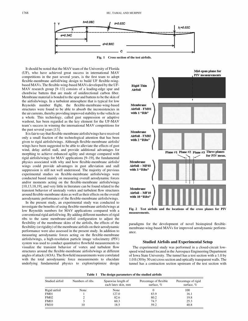
Fig. 1 Cross section of the test airfoils.
Fig. 2 Test airfoils and the locations of the cross planes for PIV
measurements.
Table 1 The design parameters of the studied airfoils
Studied airfoil Numbers of ribs Spanwise length ofeach latex skin, mm
Percentage of flexiblesurface, %
Percentage of rigidsurface, %
Rigid airfoil None None 0 100FM01 1 127.0 83.9 16.1FM02 2 82.6 80.2 19.8FM03 3 60.3 74.7 25.3FM10 10 18.5 59.2 40.8
1768 HU, TAMAI, AND MURPHY
screen structures and a cooling system installed ahead of thecontraction section to provide uniform low-turbulent incoming flowto enter the test section.All the airfoils used in the present study have the same cross-
sectional shape and chord length of 105 mm (i.e.,C� 105 mm). Asshown in Fig. 1, the airfoil cross-sectional shape design is similar tothat used by Null and Shkarayev [20]. One unique feature of theairfoil is that there exists a small inverse camber section at the rearportion of the airfoils to compensate for the high positive pitchingmoment for MAV applications. Such thin cambered airfoil shapedesign has already been used widely by several research groups tosuccessfully make functional MAVs.Figure 2 shows the five airfoils studied in the present study: a rigid
airfoil as the comparison baseline and four flexible-membraneairfoils with different numbers of rigid ribs to adjust the flexibility ofthe membrane skins of the membrane airfoils. The rigid airfoil ismade of unidirectional carbon fiber with the thickness of 1.15 mm.As shown in Fig. 2, the flexible-membrane airfoils have the samerigid main frames (leading-edge spar and two side battens), whichwere made of unidirectional carbon fiber. Flexible-membranematerial (latex sheet) is wrapped around the airfoil main frames atboth the upper and lower airfoil surfaces. Although the membraneskins are flexible and do not sustain a bending moment, the carbon-fibermain frames and ribs are rigid and can therefore sustain bendingmoment as well as provide structural support. Table 1 gives thedesign parameters of the studied airfoils. Further information aboutthe geometry design and manufacturing process of the rigid- andflexible-membrane airfoils is available in [21].In the present study, the velocity of the incoming flow was set as
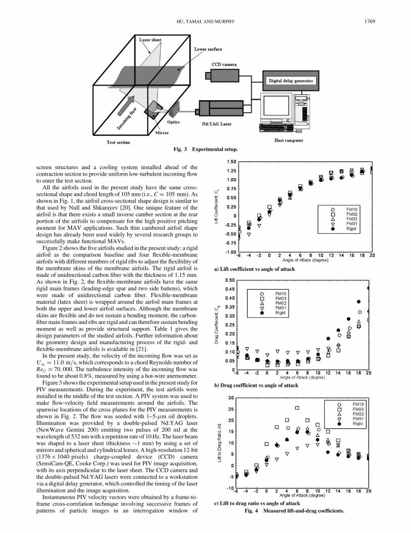
U1 � 11:0 m=s, which corresponds to a chord Reynolds number ofReC � 70; 000. The turbulence intensity of the incoming flow wasfound to be about 0.8%, measured by using a hot-wire anemometer.Figure 3 shows the experimental setup used in the present study for
PIV measurements. During the experiment, the test airfoils wereinstalled in the middle of the test section. A PIV system was used tomake flow-velocity field measurements around the airfoils. Thespanwise locations of the cross planes for the PIV measurements isshown in Fig. 2. The flow was seeded with 1–5-�m oil droplets.Illumination was provided by a double-pulsed Nd:YAG laser(NewWave Gemini 200) emitting two pulses of 200 mJ at thewavelength of 532 nmwith a repetition rate of 10Hz. The laser beamwas shaped to a laser sheet (thickness �1 mm) by using a set ofmirrors and spherical and cylindrical lenses. A high-resolution 12-bit(1376 � 1040 pixels) charge-coupled device (CCD) camera(SensiCam-QE, Cooke Corp.) was used for PIV image acquisition,with its axis perpendicular to the laser sheet. The CCD camera andthe double-pulsed Nd:YAG lasers were connected to a workstationvia a digital delay generator, which controlled the timing of the laserillumination and the image acquisition.Instantaneous PIV velocity vectors were obtained by a frame-to-
frame cross-correlation technique involving successive frames ofpatterns of particle images in an interrogation window of
Fig. 3 Experimental setup.
Fig. 4 Measured lift-and-drag coefficients.
HU, TAMAI, AND MURPHY 1769

32 � 32 pixels. An effective overlap of 50% was employed for thePIV image processing. After the instantaneous velocity vectors ui
and vi were determined, the spanwise vorticity !z could be derived.Ensemble-averaged velocity (U;V) was obtained from a cinemasequence of 400 frames of instantaneous velocity fields. Themeasurement uncertainty level for the PIV measurements isestimated to be within 2%.The aerodynamic forces (lift and drag) acting on the test airfoils
were measured by using a force-moment sensor cell (JR3, model30E12A-I40). The force-moment sensor cell is composed of foilstrain-gauge bridges, which are capable of measuring the forces onthree orthogonal axes and the moment (torque) about each axis. Theprecision of the force-moment sensor cell for force measurements is�0:25% of the full scale (40 N).
Experimental Results and Discussions
Aerodynamic Force Measurement Results
Figure 4 shows themeasurement results of the aerodynamic forcesacting on the studied airfoils in the terms of lift coefficient and dragcoefficient as the AOAof the airfoils changed from�6:0 to 20.0 deg.For the rigid thin airfoil, whereas the lift coefficient was found to
increase almost linearly with the increasing AOA, as expected, thedrag coefficient was reasonably small when the angle of attack wasrelatively low (AOA< 10:0 deg). The increase rate of the liftcoefficient was found to flatten out at relatively high angles of attack.The drag coefficient of the rigid thin airfoil was found to increase
significantly at AOA > 10:0 deg. Such characteristics revealed inthe lift- and drag-coefficient profiles indicates that airfoil stalloccurred for the rigid thin airfoil at AOA> 10:0 deg, which wasvisualized clearly from the PIV measurements to be discussed later.The flexible-membrane airfoils FM02, FM03, and FM10 were
found to have very comparable or a slightly larger lift coefficient thanthe rigid thin airfoil. The drag coefficient of the flexible-membraneairfoils was found to be significantly smaller than that of the rigid thinairfoil at relatively high angles of attack (AOA > 10:0 deg). Airfoilstall (i.e., a flattened increase rate of lift coefficient and dramaticincrease of drag coefficient) was found to occur at higher angles ofattack for theflexible-membrane airfoils than for the rigid thin airfoil.Suchmeasurement results confirmed the fact that flexible-membraneairfoils could delay airfoil stall, as suggested by previous studies[22].It should be noted that the flexible-membrane airfoil FM01, which
has only one rigid rib placed in the middle of the two rigid sidebattens (Fig. 2), is the most flexible airfoil among all the testedairfoils. During the experiments, the trailing edge of the flexible-membrane airfoil FM01 was found to be fluttering when the angle ofattack was relatively low (AOA< 10:0 deg). As a result, theflexible-membrane airfoil FM01 was found to have the worstaerodynamic performance (i.e., the smallest lift coefficient andlargest drag coefficient) among all the tested airfoils at relatively lowangles of attack (AOA< 10:0 deg). The trailing-edge flutteringphenomena were found to disappear for the FM01 airfoil when themembrane skins were stretched severely at relatively high angles of
Fig. 5 PIV measurements in the midspan plane of the rigid thin airfoil at AOA� 6:0 deg.
1770 HU, TAMAI, AND MURPHY
attack. Surprisingly, the FM01 airfoil was found to have almost thebest aerodynamic performance (i.e., small drag coefficient and highlift coefficient) among all the tested airfoils when the trailing-edgefluttering phenomena disappeared at the relatively high angle ofattack (i.e., AOA > 10:0 deg).As expected, the flexible-membrane airfoil FM10, which has 10
rigid ribs between the two side battens (and thus the least flexibilityamong the tested flexible-membrane airfoils) was found to have anaerodynamic performance very similar to the rigid thin airfoil. Theflexible-membrane airfoil FM03 was found to have the bestaerodynamic performance (e.g., largest lift coefficient and smallestdrag coefficient) among all the test airfoils, with the lift-to-drag ratiobeing up to 25.5 at AOA� 6:0 deg.The aerodynamic force measurement results revealed that the
flexibility (or rigidity) of the membrane skins could significantlyaffect the aerodynamic performance of the membrane airfoils.Therefore, it is important to chose a proper flexibility (or rigidity) ofthe membrane skins to achieve improved aerodynamic performanceby using flexible-membrane airfoils at low Reynolds numbers forMAV applications.
PIV Measurement Results
With the findings derived from the aerodynamic forcemeasurements in mind, PIV measurements were carried out tovisualize the transient behavior of vortex and turbulent flowstructures around the flexible-membrane airfoils compared with
those around the rigid airfoil to reveal the underlying fundamentalphysics associated with the airfoil aerodynamic performancecharacteristics revealed from the aerodynamic force measurements.Figure 5 shows the PIV measurement results of the flowfield
around the rigid thin airfoil at AOA� 6:0 deg. As indicated inFig. 2, the PIV measurement was conducted in the midspan for therigid airfoil. Because the adverse pressure gradient over the uppersurface of the rigid airfoil was rather mild at AOA� 6:0 deg, theinstantaneous and ensemble-averaged measurement results revealedclearly that incoming streams could follow the curved upper surfaceof the rigid airfoil. A boundary layer was visualized clearly in theinstantaneous vorticity distribution as a thin vortex layer affixing tothe airfoil upper surface. The boundary layer was found to attach tothe airfoil upper surface from the leading edge all the way to thetrailing edge. The streamlines of the mean flowfield shows clearlythat because the incoming flow streams could flow smoothly tofollow the curved surface of the rigid thin airfoil atAOA� 6:0 deg,they left the airfoil trailing edge smoothly, which resulted in a verysmall wake region (i.e., the regionwith velocity deficits) downstreamof the airfoil. The small wake region downstream of the airfoilindicated a small aerodynamic drag force acting on the airfoil, whichwas confirmed from the aerodynamic force measurements given inFig. 4.The results of the PIV measurements conducted in the midspan
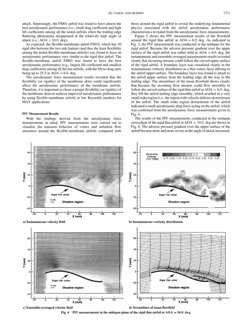
cross plane of the rigid thin airfoil atAOA� 10:0 deg are shown inFig. 6. The adverse pressure gradient over the upper surface of theairfoil becamemore andmore severe as the angle of attack increased.
Fig. 6 PIV measurements in the midspan plane of the rigid thin airfoil at AOA� 10:0 deg.
HU, TAMAI, AND MURPHY 1771

The instantaneous PIV measurement results show clearly thatincoming flow streams could not flow smoothly to follow the curvedupper surface of the rigid thin airfoil anymore, due to more severeadverse pressure gradient at AOA� 10:0 deg. The boundary-layerflow (i.e, the vortex layer attached to the airfoil surface near theairfoil leading edge) was found to separate from the airfoilupper surface of the airfoil. Strong, unsteady vortex structures werefound to be generated in the wake of the rigid thin airfoil as a resultof the boundary-layer flow separation. The flow separation on theupper surface of the airfoil can also be seen clearly from theensemble-averaged PIV measurement results in the form of aseparation bubble near the trailing edge of the airfoil. Because of theflow separation, the size of the wake region (i.e. the regionwith velocity deficits) downstream of the rigid thin airfoil was foundto be increased greatly, which indicates an increased aerodynamicdrag force acting on the airfoil. The increased aerodynamicdrag acting on the rigid thin airfoil at AOA� 10:0 deg wasconfirmed quantitatively for the measured drag-coefficient datagiven in Fig. 4.Figure 7 gives the PIVmeasurement results of theflowfield around
the rigid thin airfoil as the angle of attack increased to 14.0 deg (i.e.,AOA� 14:0 deg). The significant adverse pressure gradient overthe upper surface of the airfoil atAOA� 14:0 deg caused incomingflow streams to separate from the airfoil upper surface almost fromthe leading edge of the airfoil; that is, the separation point of theboundary-layer flow was pushed upstream approaching the airfoil
leading edge, due to the significant adverse pressure gradient.Large-scale flow separation was found to take place on almost theentire upper surface of the rigid thin airfoil. Very strong, unsteadyvortex structures were found to be generated in the wake of the rigidairfoil. As a result, a very large recirculation bubble was found to beformed in the wake of the rigid thin airfoil, which indicates that theairfoil was in a deep-stall state. As revealed quantitatively from theaerodynamic force measurement data given in Fig. 4, theaerodynamic performance of the airfoil was found to degradesignificantly, with the drag coefficient of the airfoil increasingdramatically at AOA� 14:0 deg.Although the flexible-membrane airfoils were designed to have
the same cross-sectional shape as the rigid thin airfoil, flexible-membrane skins allow the flexible-membrane airfoils to be able toadjust their cross-sectional shape automatically to adapt to incomingflows to balance the pressure differences on the upper and lowersurfaces of the flexible-membrane airfoils at different angles ofattack. As shown in Fig. 2, PIV measurements were conducted inthree different cross planes along the spanwise direction for theflexible-membrane airfoil FM03. Measurement plane 1 is located inthe middle plane between the first and second rigid ribs for theMF03airfoil, where the membrane skin of the airfoil was found to be themost flexible, and maximum deformation of the cross-sectionalshape was observed during the experiments. Measurement plane 3was selected to be in the center plane of the second rigid rib, which isalso the midspan of the FM03 airfoil. Because the rib is rigid, the
Fig. 7 PIV measurements in the midspan plane of the rigid thin airfoil at AOA� 14:0 deg.
1772 HU, TAMAI, AND MURPHY

cross-sectional shape of the airfoil inmeasurement plane 3would notbe deformed during the experiments. Measurement plane 2 wasselected to be in the middle plane between measurement plane 1 andmeasurement plane 3, where the cross section of the airfoil was foundto deform during the experiments. However, the deformationamplitude in measurement plane 2 was found to be much moremoderate than that in measurement plane 1.The PIV measurement results of the vortex and turbulent flow
structures around the FM03 airfoil in the threemeasurement planes atdifferent angles of attack are given in Figs. 8–12. The bold dashedlines in the figures indicate the original cross-sectional shape (i.e.,designed shape without any deformation) of the FM03 airfoil, andthe bold solid lines indicate the actual cross-sectional shapes of theFM03 airfoil in the measurement planes extracted from PIV rawimages.For the rigid thin airfoil, as revealed in the PIV measurement
results given in Fig. 6, incoming flow streams were found to separatefrom the upper surface of the rigid thin airfoil due to a severe adversepressure gradient at AOA� 10:0 deg. As visualized clearly fromthe PIV measurement results given in Fig. 8, because the flexible-membrane airfoil FM03 could change its chamber shape (i.e., theshape of the cross section) automatically to adapt incoming flowstreams to balance the pressure differences on the upper and lowersurfaces of the airfoil, incoming flow streams were found to stayfirmly attached to the deformed membrane skin in measurementplane 1 from the airfoil leading edge all the way down to the airfoiltrailing edge at AOA� 10:0 deg. No large-scale flow separationwas found on the upper surface of the FM03 airfoil in measurement
plane 1. Both the instantaneous and ensemble-averaged PIVmeasurement results revealed clearly that the wake region (i.e., theregion with velocity deficits) downstream of the FM03 airfoil inmeasurement plane 1 is quite small because incoming flow streamscan stay attached to the deformed airfoil upper surface atAOA� 10:0 deg. The small wake region indicates a smallaerodynamic drag force acting on the FM03 airfoil, which wasconfirmed from the aerodynamic drag force measurements given inFig. 4.As visualized clearly from the PIV measurement results given in
Fig. 7, the rigid thin airfoil was found to stall completely at AOA�14:0 deg due to the significant adverse pressure gradient on theupper surface of the airfoil. Figures 9–11 show the PIVmeasurementresults of the flow structures around the FM03 airfoil at AOA�14:0 deg in measurement planes 1, 2, and 3, respectively.From the PIV measurement results shown in Fig. 9, it can be seen
clearly that the deformation to the cross-sectional shape of the FM03airfoil in measurement plane 1 became more severe at AOA�14:0 deg than those at smaller angles of attack (such as the case ofAOA� 10:0 deg, shown in Fig. 8). In addition to changing airfoilcross-sectional shape more severely to balance the pressuredifferences on the upper and lower surfaces of the airfoil atAOA� 14:0 deg, significant airfoil trailing-edge defection (i.e., tolift the airfoil trailing edge up from its original position) was alsofound for the FM03 airfoil in measurement plane 1, due to the moresevere pressure difference at AOA� 14:0 deg, which resulted in aconsiderable reduction of the effective angle of attack inmeasurement plane 1. Because of the deformed cross-sectional
Fig. 8 PIV measurements in measurement plane 1 for the FM03 airfoil at AOA� 10:0 deg.
HU, TAMAI, AND MURPHY 1773

shape and the effective-angle-of-attack reduction, incoming flowstreams were found to be able to stay attached to the deformed airfoilsurface in measurement plane 1 for the FM03 airfoil atAOA� 14:0 deg. As a result, the wake region downstream of theFM03 airfoil was found to be still reasonably small in measurementplane 1, whereas a very big recirculation bubblewas already found toform downstream of the rigid airfoil at the same angle of attack ofAOA� 14:0 deg. Compared with those at smaller angles of attack(such as the case shown in Fig. 8 withAOA� 10:0 deg), the size ofthe wake region in measurement plane 1 was found to becomeslightly larger, indicating an increased aerodynamic drag force actingon the airfoil, which is confirmed from the measured airfoil dragcoefficient given in Fig. 4.As shown in Fig. 10, the deformation of the cross-sectional profile
of the FM03 airfoil in measurement plane 2 was found to be muchmore moderate than that in measurement plane 1 at the same angle ofattack of AOA� 14:0 deg. Instead of having incoming flowstreams attached to the deformed airfoil upper surface from theleading edge to the trailing edge aswith those inmeasurement plane 1shown in Fig. 9, a time sequence of the instantaneous PIVmeasurement results in measurement plane 2 revealed that incomingstreams would separate from the airfoil upper surface at the rearportion of the airfoil from time to time, accompanied by shedding ofunsteady vortex structures in the wake of the airfoil. The ensemble-averaged velocity and corresponding streamline distributions revealthat, whereas incoming flow streams were found to follow the frontportion of the deformed profile at the airfoil cross section in
measurement plane 2, flow separation near the airfoil trailing edgecan be seen clearly from the ensemble-averaged PIV measurementresults. As a result, a larger wake region with velocity deficits wasfound downstream of the FM03 airfoil in measurement plane 2 thanthat in measurement plane 1 for the FM03 airfoil at the same angle ofattack of AOA� 14:0 deg.Figure 11 shows the PIV measurement results in measurement
plane 3 for the FM03 airfoil at AOA� 14:0 deg. As alreadydescribed, because the ribs of the FM03 airfoil are rigid, the cross-sectional shape of the airfoil would not be changed in measurementplane 3 during the experiments. The incoming flow streams werefound to separate from the airfoil upper surface from a location veryclose to the airfoil leading edge in measurement plane 3. Large-scaleflow separation was found to take place on almost the entire uppersurface of the airfoil, which results in a very large recirculation regionformed downstream of the FM03 airfoil in measurement plane 3, asvisualized clearly in the distributions of the ensemble-averagedvelocity and corresponding streamlines. It should be noted that theflow pattern in measurement plane 3 for the FM03 airfoil at AOA�14:0 degwas found to be quite similar to that of the rigid thin airfoilat the same angle of attack of attack ofAOA� 14:0 deg. However,the size of the recirculation bubble in measurement plane 3 behindthe FM03 airfoil was found to be smaller than that in the wake of therigid thin airfoil shown in Fig. 7. The PIV measurements againindicate a smaller aerodynamic drag force acting on the FM03 airfoilthan on the rigid thin airfoil, which is confirmed from the measuredairfoil drag-coefficient data given in Fig. 4.
Fig. 9 PIV measurements in measurement plane 1 for the FM03 airfoil at AOA� 14:0 deg.
1774 HU, TAMAI, AND MURPHY
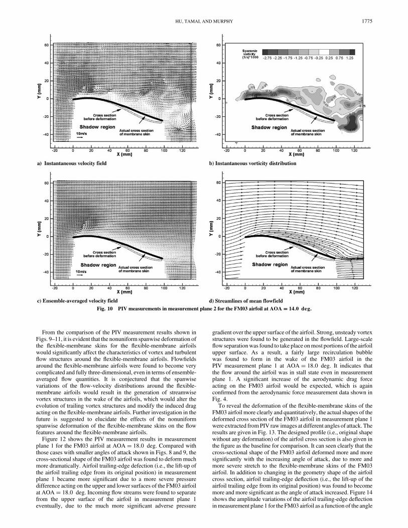
From the comparison of the PIV measurement results shown inFigs. 9–11, it is evident that the nonuniform spanwise deformation ofthe flexible-membrane skins for the flexible-membrane airfoilswould significantly affect the characteristics of vortex and turbulentflow structures around the flexible-membrane airfoils. Flowfieldsaround the flexible-membrane airfoils were found to become verycomplicated and fully three-dimensional, even in terms of ensemble-averaged flow quantities. It is conjectured that the spanwisevariations of the flow-velocity distributions around the flexible-membrane airfoils would result in the generation of streamwisevortex structures in the wake of the airfoils, which would alter theevolution of trailing vortex structures and modify the induced dragacting on the flexible-membrane airfoils. Further investigation in thefuture is suggested to elucidate the effects of the nonuniformspanwise deformation of the flexible-membrane skins on the flowfeatures around the flexible-membrane airfoils.Figure 12 shows the PIV measurement results in measurement
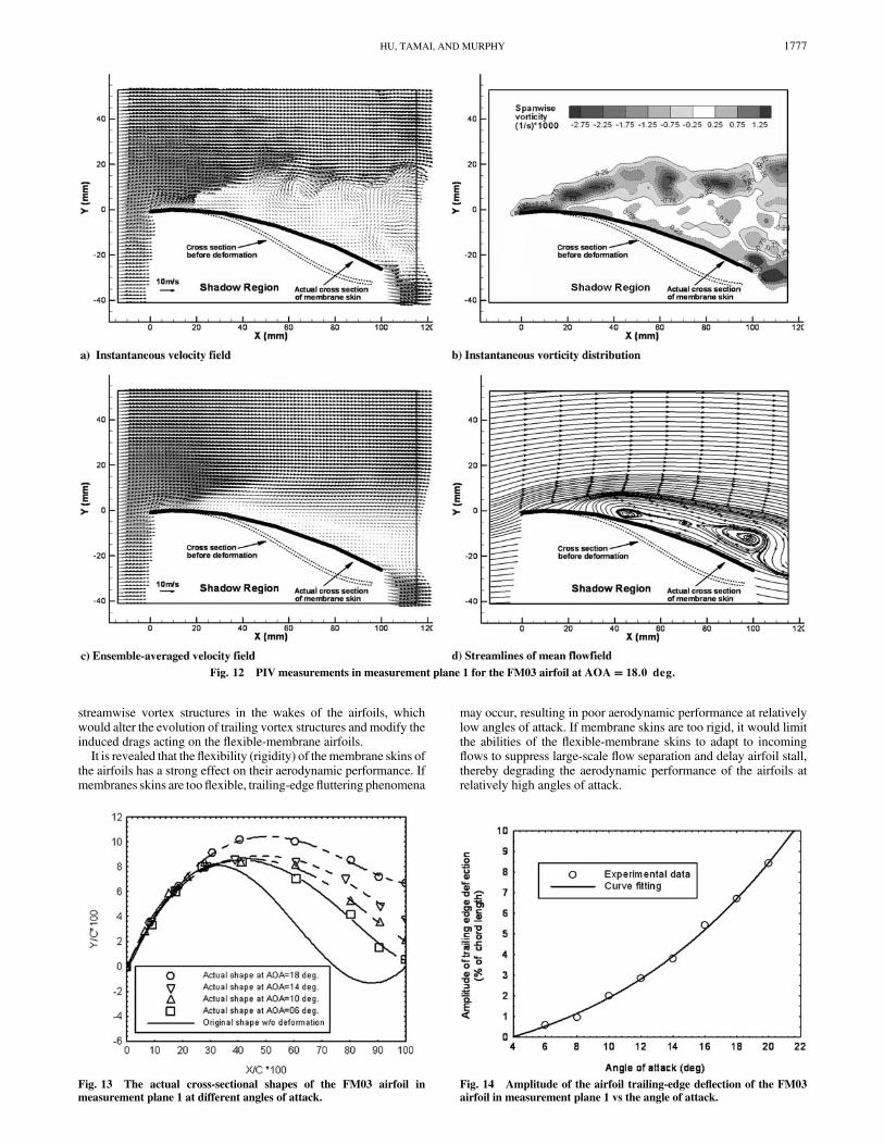
plane 1 for the FM03 airfoil at AOA� 18:0 deg. Compared withthose cases with smaller angles of attack shown in Figs. 8 and 9, thecross-sectional shape of the FM03 airfoil was found to deformmuchmore dramatically. Airfoil trailing-edge defection (i.e., the lift-up ofthe airfoil trailing edge from its original position) in measurementplane 1 became more significant due to a more severe pressuredifference acting on the upper and lower surfaces of the FM03 airfoilat AOA� 18:0 deg. Incoming flow streams were found to separatefrom the upper surface of the airfoil in measurement plane 1eventually, due to the much more significant adverse pressure
gradient over the upper surface of the airfoil. Strong, unsteady vortexstructures were found to be generated in the flowfield. Large-scaleflow separationwas found to take place onmost portions of the airfoilupper surface. As a result, a fairly large recirculation bubblewas found to form in the wake of the FM03 airfoil in thePIV measurement plane 1 at AOA� 18:0 deg. It indicates thatthe flow around the airfoil was in stall state even in measurementplane 1. A significant increase of the aerodynamic drag forceacting on the FM03 airfoil would be expected, which is againconfirmed from the aerodynamic force measurement data shown inFig. 4.To reveal the deformation of the flexible-membrane skins of the
FM03 airfoil more clearly and quantitatively, the actual shapes of thedeformed cross section of the FM03 airfoil in measurement plane 1were extracted fromPIV raw images at different angles of attack. Theresults are given in Fig. 13. The designed profile (i.e., original shapewithout any deformation) of the airfoil cross section is also given inthe figure as the baseline for comparison. It can seen clearly that thecross-sectional shape of the FM03 airfoil deformed more and moresignificantly with the increasing angle of attack, due to more andmore severe stretch to the flexible-membrane skins of the FM03airfoil. In addition to changing in the geometry shape of the airfoilcross section, airfoil trailing-edge deflection (i.e., the lift-up of theairfoil trailing edge from its original position) was found to becomemore and more significant as the angle of attack increased. Figure 14shows the amplitude variations of the airfoil trailing-edge deflectioninmeasurement plane 1 for the FM03 airfoil as a function of the angle
Fig. 10 PIV measurements in measurement plane 2 for the FM03 airfoil at AOA� 14:0 deg.
HU, TAMAI, AND MURPHY 1775

of attack. It can been seen clearly that the deflection amplitudeincreased rapidly as the angle of attack of the airfoil increased. Theamplitude of the trailing-edge deflection inmeasurement plane 1wasfound to be as high as 6.8%of the chord length for the FM03 airfoil atAOA� 18:0 deg.
Conclusions
An experimental study was conducted to quantify the benefits ofusingflexible-membrane airfoils/wings at lowReynolds numbers forMAV applications compared with their rigid counterpart. Theexperiments were conducted in a wind tunnel with the chordReynolds number ofRec � 70; 000. By adding different numbers ofrigid ribs to the same membrane-airfoil configuration to adjust theflexibility of the membrane skins of the airfoils, the effects of theflexibility of the membrane airfoils on their aerodynamicperformance were assessed in the present study. In addition tomeasuring aerodynamic forces (lift and drag) acting on the flexible-membrane airfoils/wings, a high-resolution particle imagevelocimetry (PIV) system was be used to conduct detailed flowfieldmeasurements to visualize the transient behavior of vortex andturbulent flow structures around the flexible-membrane airfoils/wings compared with those around a rigid thin airfoil at differentangles of attack. The flowfield measurements were correlated withthe aerodynamic force measurements to elucidate the underlying
fundamental physics to explore/optimize design paradigms for thedevelopment of novel bioinspired flexible-membrane-wing-basedMAVs for improved aerodynamic performance.The aerodynamic force measurement results elucidated clearly
that flexible-membrane airfoils/wings could provide betteraerodynamic performance than their rigid counterpart. The PIVmeasurements elucidated that flexible-membrane airfoils couldchange their camber (i.e., cross-sectional shape) automatically toadapt to incoming flows to balance the pressure differences on theupper and lower surfaces of the airfoils, thereby suppressing large-scale flow separation on the airfoil upper surfaces. Meanwhile,deformations of the flexible-membrane skins were found to causesignificant airfoil trailing-edge deflections (i.e., to lift the airfoiltrailing edge up from its original designed position), which resultedin reduction of the effective angles of attack of the flexible-membrane airfoils, thereby delaying airfoil stall at high angles ofattack.The PIV measurements also revealed that the nonuniform
spanwise deformation of the flexible-membrane skins for theflexible-membrane airfoils significantly affected the characteristicsof vortex and turbulentflow structures around theflexible-membraneairfoils. Flowfields around the flexible-membrane airfoils werefound to become very complicated and fully three-dimensional, evenin terms of ensemble-averaged flow quantities. It is conjectured thatthe spanwise variations of the flow-velocity distributions around theflexible-membrane airfoils would result in the generation of
Fig. 11 PIV measurements in measurement plane 3 for the FM03 airfoil at AOA� 14:0 deg.
1776 HU, TAMAI, AND MURPHY
streamwise vortex structures in the wakes of the airfoils, whichwould alter the evolution of trailing vortex structures and modify theinduced drags acting on the flexible-membrane airfoils.It is revealed that the flexibility (rigidity) of themembrane skins of
the airfoils has a strong effect on their aerodynamic performance. Ifmembranes skins are tooflexible, trailing-edge fluttering phenomena
may occur, resulting in poor aerodynamic performance at relativelylow angles of attack. If membrane skins are too rigid, it would limitthe abilities of the flexible-membrane skins to adapt to incomingflows to suppress large-scale flow separation and delay airfoil stall,thereby degrading the aerodynamic performance of the airfoils atrelatively high angles of attack.
Fig. 12 PIV measurements in measurement plane 1 for the FM03 airfoil at AOA� 18:0 deg.
Fig. 13 The actual cross-sectional shapes of the FM03 airfoil in
measurement plane 1 at different angles of attack.
Fig. 14 Amplitude of the airfoil trailing-edge deflection of the FM03
airfoil in measurement plane 1 vs the angle of attack.
HU, TAMAI, AND MURPHY 1777
Acknowledgment
The support of National Science Foundation CAREER programunder award number CTS-0545918 is gratefully acknowledged.
References
[1] Carmichael, B. H., “Low Reynolds number airfoil Survey,” Vol. 1,NASA CR-165803, 1981.
[2] Lissaman, P. B. S., “Low-Reynolds-Number Airfoils,” Annual Reviewof Fluid Mechanics, Vol. 15, 1983, pp. 223–239.doi:10.1146/annurev.fl.15.010183.001255
[3] Gad-el-Hak, M., “Micro-Air-Vehicles: Can They be ControlledBetter,” Journal of Aircraft, Vol. 38, No. 3, 2001, pp. 419–429.
[4] Mueller T. J. (ed.), Fixed and Flapping Wing Aerodynamics for Micro
Air Vehicle Applications, Progress in Astronautics and Aeronautics,AIAA, Reston, VA, 2001.
[5] Galvao, R., Israeli, E., Song, A., Tian, X., Bishop, K., Swartz, S., andBreuer, K., “The Aerodynamics of Compliant Membrane WingsModeled on Mammalian Flight Mechanics,” AIAA Paper 2006-2866,2006.
[6] Weinstein, R., Hueso, E., Pivkin, I., Swartz, S., Laidlaw, D. H.,Karniadakis, G., and Breuer, K. S., “Simulation and Visualization ofFlow Around Bat Wings During Flight,” SIGGRAPH 2004 [CD-ROM], ACM Press, New York, 2004.
[7] Swartz, S., Diaz, J., Riskin, D. K., Song, A., Tian, X., Willis, D. J., andBreuer, K. S., “Wing Structure and the Aerodynamic Basis of Flight inBats,” AIAA Paper 2007-0042, 2007.
[8] Song, A., and Breuer, K., “Dynamics of a Compliant Membrane asRelated to Mammalian Flight,” AIAA Paper 2007-665, 2007.
[9] Ifju, P. G., Ettinger, S., Jenkins, D. A., and Martinez, L., “CompositeMaterials for Micro Air Vehicles,” SAMPE Journal, Vol. 37, No. 4,2001, pp. 7–13.
[10] Albertani, R., Boria, F., Bowman, S., Claxton, D., Crespo, A., Francis,C., Ifju, P., Johnson, B., Lee, H. K., Morton, M., and Sytsma, M.,“Development of Reliable and Mission Capable Micro-Air-Vehicles,”9th International MAV Competition, 2005, pp. 1–10.
[11] Shyy,W.,Ifju,P.,andViieru,D.,“MembraneWing-BasedMicroAirVe-hicles,”AppliedMechanicsReviews, Vol. 58,No. 4, 2005, pp. 283–301.doi:10.1115/1.1946067
[12] Albertani, R., Stanford, B., Hubner, J. P., and Ifju, P. G., “AerodynamicCoefficients and Deformation Measurements on Flexible Micro AirVehicle Wings,” Experimental Mechanics, Vol. 47, No. 5, 2007,pp. 625–635.doi:10.1007/s11340-006-9025-5
[13] Abdulrahim, M., “Dynamic Characteristics of Morphing Micro AirVehicles,” M.S., Thesis, Dept. of Mechanical and AerospaceEngineering, Univ. of Florida, Gainesville, FL, 2004.
[14] Smith, R. W., and Shyy, W., “Computation of Unsteady Laminar FlowOver a Flexible Two-Dimensional Membrane Wing,” Physics of
Fluids, Vol. 7, No. 9, 1995, pp. 2175–2184.doi:10.1063/1.868467
[15] Shyy, W., Berg, M., and Ljunqvist, D., “Flapping and Flexible Wingsfor Biological and Micro Air Vehicles,” Progress in Aerospace
Sciences, Vol. 35, No. 5, 1999, pp. 455–506.doi:10.1016/S0376-0421(98)00016-5
[16] Shyy, W., Jenkins, D. A., and Smith, R. W., “Study of Adaptive ShapeAirfoils at LowReynoldsNumber inOscillatory Flows,”AIAA Journal,Vol. 35, No. 9, 1997, pp. 1545–1548.
[17] Tang, J., Viieru, D., and Shyy, W., “A Study of Aerodynamics of LowReynolds Number Flexible Airfoils,” AIAA Paper 2007-4212, 2007.
[18] Waszak, R. M., Jenkins, N. L., and Ifju, P., “Stability and ControlProperties of an Aeroelastic Fixed Wing Micro Aerial Vehicle,”AIAAPaper 2001-4005, 2001.
[19] Warkentin, J., and DeLaurier, J., “Experimental Aerodynamic Study ofTandem Flapping Membrane Wings,” Journal of Aircraft, Vol. 44,No. 5, 2007, pp. 1653–1661.doi:10.2514/1.28160
[20] Null,W., and Shkarayev, S., “Effect of Camber on theAerodynamics ofAdaptive-Wing Micro Air Vehicles,” Journal of Aircraft, Vol. 42,No. 6, 2005, pp. 1537–1642.doi:10.2514/1.12401
[21] Tamai, M., “Experimental Investigations on Biologically InspiredAirfoils for MAV Applications,”M.S. Thesis, Aerospace EngineeringDept., Iowa State Univ., Ames, IA, 2007.
[22] Lian, Y., and Shyy, W., “Three-Dimensional Fluid-StructureInteractions of aMembraneWing forMicro Air Vehicle Applications,”Journal of Aircraft, Vol. 42, No. 4, 2005, pp. 865–873.doi:10.2514/1.5909
1778 HU, TAMAI, AND MURPHY


![Dynamic Stall on Airfoils Exposed to Constant Pitch-Rate ... Pap… · investigating pitch rate, Reynolds number, airfoil geometry and Mach number [4, 6] all seek to identify key](https://img.pdfslide.net/doc/110x75/5f4d418c5881a577222dc2c1/dynamic-stall-on-airfoils-exposed-to-constant-pitch-rate-pap-investigating.jpg)