Embed Size (px)
Citation preview
STATE OF CALIFORNIA
California Department
of Transportation
FLEXIBLE PAVEMENT
REHABILITATION MANUAL
Revised: June 1, 2001
Flexible Pavement Rehabilitation Manual June 2001 ______________________________________________________________________________________
ii
DISCLAIMER This manual is intended for the use of Caltrans personnel. Engineers and agencies outside of Caltrans may use this manual at their own discretion. Caltrans is not responsible for any work performed by non-Caltrans personnel using this manual.
ACKNOWLEDGMENT
The information contained in this manual is a result of efforts of many individuals in the Structural Section Design and Rehabilitation Branch (SSD&R). Gary Mann, P.E. and Paul Mason, P.E., with a combined experience of 40 years of pavement structural section design and rehabilitation, are the principal authors of this publication. The contributions of engineers and technicians who have worked and are presently working in SSD&R are also acknowledged.
Flexible Pavement Rehabilitation Manual June 2001 ______________________________________________________________________________________
iii
TABLE OF CONTENTS Chapter - Section 1 GENERAL
1 – 10 Background 1 – 20 Foreword
2 PERFORMING A DEFLECTION STUDY 2 – 10 Equipment 2 – 20 Establishing Test Sections 2 – 30 Pavement Background Information 2 – 40 Collecting Field Data 2 – 50 Measuring Deflections 2 – 60 Converting to Equivalent Deflectometer Values 2 – 70 Mean and 80th Percentile Deflections 2 – 80 Preparing a Deflection Map
3 INTRODUCTION TO AC PAVEMENT REHABILITATION DESIGN 3 – 10 Design Governed by Structural Adequacy 3 – 20 Design Governed by Reflective Cracking 3 – 30 Design Governed by Ride Quality 3 – 40 Choosing the Design Recommendation
4 FLEXIBLE PAVEMENT REHABILITATION DESIGN GUIDE
4 – 10 Basic Overlay Using DGAC 4 – 20 Rubberized Asphalt Concrete (Type G) 4 – 30 Stress Absorbing Membrane Interlayers 4 – 40 Cold Recycled Asphalt Concrete Pavement 4 – 50 Hot Recycled Asphalt Concrete Pavement 4 – 60 Remove and Replace 4 – 70 Asphalt Concrete Overlay Placed on a Cushion Course 4 – 80 Cushion Course Design With Drainage Layer 4 – 90 Asphalt Concrete Overlay With Drainage Layer
5 APPENDIX 5 – 10 Guidelines for Involving Moisture and Temperature in Flexible Pavement Rehabilitation 5 – 20 Identifying and Recording Distress 5 – 30 Abbreviations 5 – 40 Definitions 5 – 50 Bibliography
6 TABLES
Flexible Pavement Rehabilitation Manual June 2001 ______________________________________________________________________________________
1-1
CHAPTER 1
GENERAL
This manual delineates the basic design strategies of the 1979 “Asphalt Concrete Overlay Design Manual” plus the many changes in procedures, and incorporates the use of new strategies and materials presently being used by Caltrans. It is intended as a tool to provide guidance to those who are recommending asphalt concrete pavement rehabilitation for planning, design and maintenance of the state’s highways. Caution and engineering judgment must be exercised throughout the investigation and design process.
1 – 10 Background Since 1938, deflection measurements have been utilized for the evaluation of flexible pavement. In 1951, the Laboratory at the Division of Highways initiated a series of comprehensive deflection research studies in an effort to establish relationships between pavement deflections and pavement performance. The results and conclusions of the first formal study were published in 1955 (1). An evaluation of the data, with respect to pavement deflections versus pavement conditions, permitted the establishment of the concept of "tolerable deflection" criteria for a variety of asphalt concrete (AC) structural sections*. Tolerable
* The term "tolerable deflection," refers to the level beyond which repeated deflections of that magnitude would produce fatigue cracking in the surface prior to the planned design period of the pavement.
deflections eventually provided the basis for the application of pavement deflection data to overlay design. However, since tolerable deflection values were collected for roads with Traffic Indices (TI’s) of approximately 9, results of laboratory fatigue tests on asphalt concrete samples were used to establish a method to adjust tolerable deflection levels for other TI values (2).
In 1960, California began using deflection data in conjunction with the tolerable deflection as the basis for overlay design. Data accumulated on the deflection values for various thicknesses of AC pavement with cement treated base, or aggregate base, subjected to various traffic loadings along with the tolerable deflection criteria already established, provided the basis of the Caltrans overlay design procedure. By 1966, approximately 80 overlay projects; including state highways, county roads, and city streets; had been designed by deflection analysis.
After almost 20 years of research into determining asphalt concrete pavement deflections and relating these deflections to pavement performance,(3) the data collection and design procedures were formally adopted in 1969. California Test Method 356 “Methods of Test to Determine Flexible Pavement Rehabilitation Requirements By Pavement Deflection Measurements,”(4) defined pavement rehabilitation requirements on state highways in California. During this time the primary overlay material was dense graded asphalt concrete.
In 1974, changes based on the performance of newly constructed highway projects under study since 1964
Flexible Pavement Rehabilitation Manual June 2001 ______________________________________________________________________________________
1-2
simplified the procedure for determining an AC overlay thickness (3). Revised deflection attenuation data and tolerable deflection levels of AC pavements were also included.
In 1979, the “Asphalt Concrete Overlay Design Manual”(5) was published. This manual provided the methods: (1) to be used for acquiring information regarding the existing asphalt concrete pavement, (2) to design AC pavement overlays using deflections for structural adequacy based on California Test 356, (3) to retard reflective cracking and (4) to restore ride quality.
Environmental concerns and the State’s commitment to recycle as much roadway material as economics permit have also influenced rehabilitation methods. Consequently, over the past 21 years, Caltrans* rehabilitation strategies have increased in number with new materials, interlayers, recycling of existing pavements, and the addition of waste products (such as rubber) in asphalt concrete.
A study was published in 1980 (6) that reviewed the actual service life of pavement overlays designed by California Test Method 356. The design period of the overlays in this study was 10 years. The average service life was found to be 11.6 years. Judgment as to length of service was recognized to be entirely subjective and, thus, susceptible to variation. However, the term “service life" was defined in this report as the period of time until the extent of load-associated alligator cracking or patching reached a combined total of 30 percent * The California Division of Highways became the California Department of Transportation (Caltrans) on July 1, 1973.
of the roadway wheel path areas. (One wheel path with continuous alligator cracking was considered to be 50 percent and continuous cracking in both wheel paths would be 100%.)
1 – 20 Foreword
Headquarters Maintenance along with each district office determines which portions of the California highway system are candidates for rehabilitation. The Pavement Management System (PMS) is the primary tool used in determining where repairs are needed and how available funds will be apportioned statewide.
Besides rehabilitation for structural adequacy, when an existing roadway is being widened the existing pavement should be brought up to the same life expectancy as the new pavement.
The Pavement Condition Inventory, a report generated under the PMS, will “trigger” a section of roadway when the ride quality is poor. The design for alleviating a poor ride problem should also provide an increased service life for the pavement (normally 10 years).
When the new lanes are added, the existing shoulder may be called upon to carry a wheel path. A deflection study will determine if it will support the new loads or if any up-grade is necessary.
When construction requires that public traffic be detoured to an existing street or roadway for a period of time, a before-and-after study may be necessary to determine the extent of added distress and to develop a recommendation to bring the pavement back to its intended service life.
Flexible Pavement Rehabilitation Manual June 2001 ______________________________________________________________________________________
1-3
Each design requires an evaluation based on three components: providing structural adequacy, retarding reflective cracking from the underlying layer and improving the ride quality.
The project engineer should consult the regional or district materials engineer or the district pavement engineer early in the project development process in order to reduce the lag time between conception and construction of the project. Pavement deflection studies and rehabilitation recommendations should be requested early in the process to provide accurate information for estimating project costs.
Development of a recommendation to rehabilitate an existing AC pavement requires collecting background data as well as collecting field data. Thorough investigation of the pavement surface, deflection measurements of the existing pavement and knowledge of the subsurface conditions are all necessary. Finally, all the assembled information previously acquired, along with the calculations, are used to determine the amount of rehabilitation necessary to
return the roadway to an acceptable level of service.
There are many variations in materials, traffic loads and environment that affect the performance of pavement structural sections. This makes it impossible to develop hard and fast rules for the rehabilitation of pavements. Therefore, the project engineer should rely on the experience, judgment and guidance of engineers in pertinent functional engineering areas who are familiar with design, construction, materials, and maintenance of pavements in the geographical area of the project.
The use of the metric system is encouraged and prevalent in State contracts. However, the English system lends itself better to the use of this manual since deflections in all previous research and current field studies are measured in thousands of an inch (0.001-inch) for the California Deflectometer as well as other devices. All calculations in this manual are in the English system and final results are in metric equivalent.
Flexible Pavement Rehabilitation Manual June 2001 ______________________________________________________________________________________
2-1
CHAPTER 2
PERFORMING A DEFLECTION STUDY
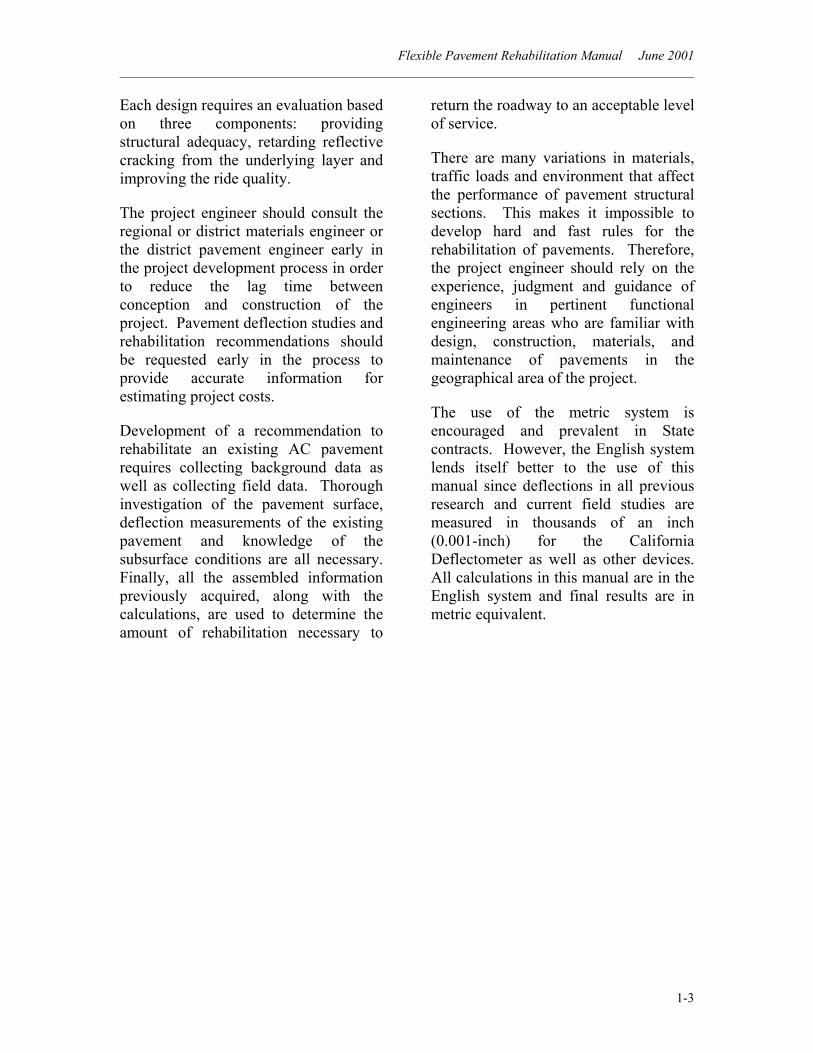
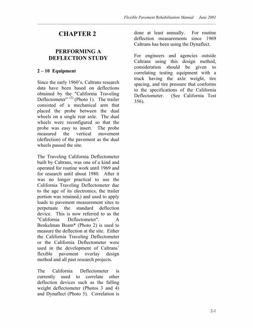
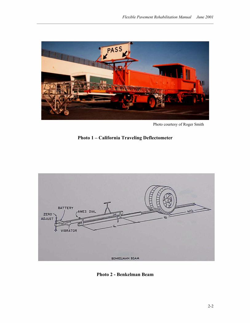
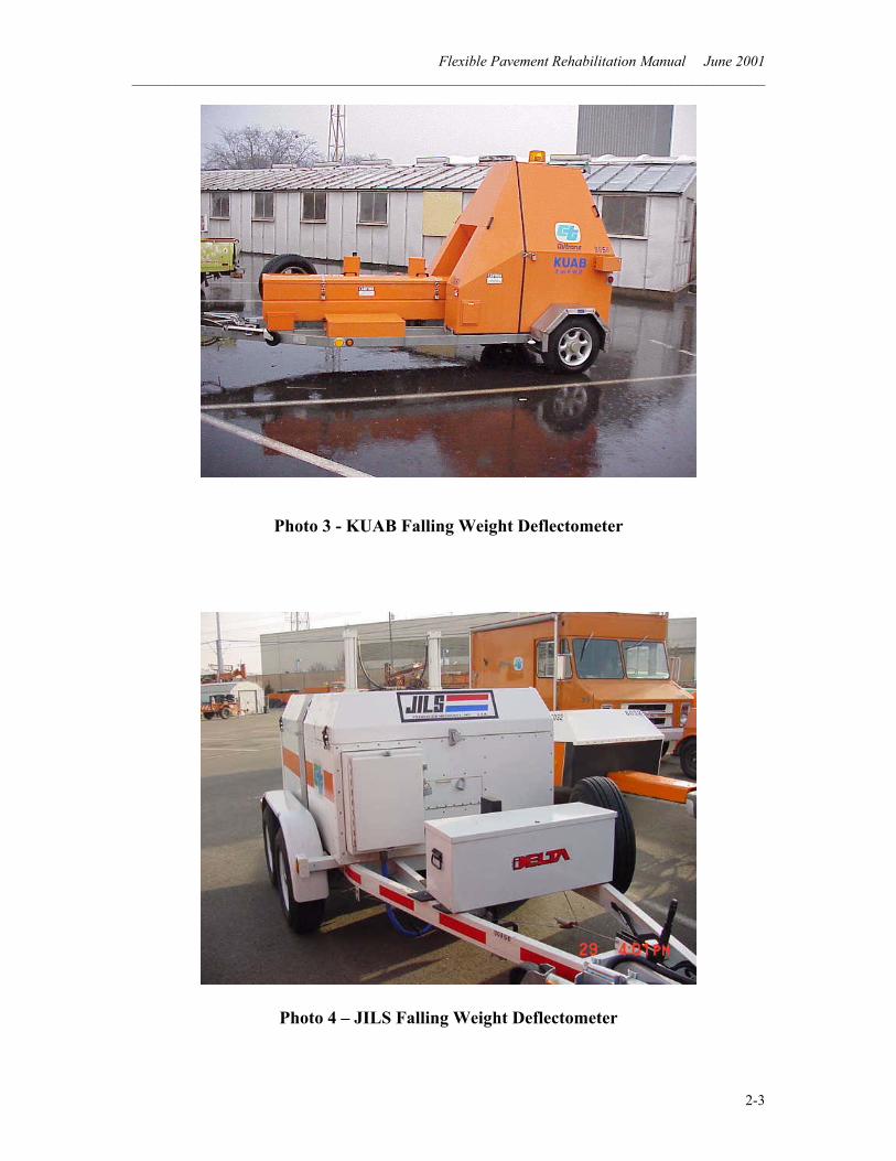
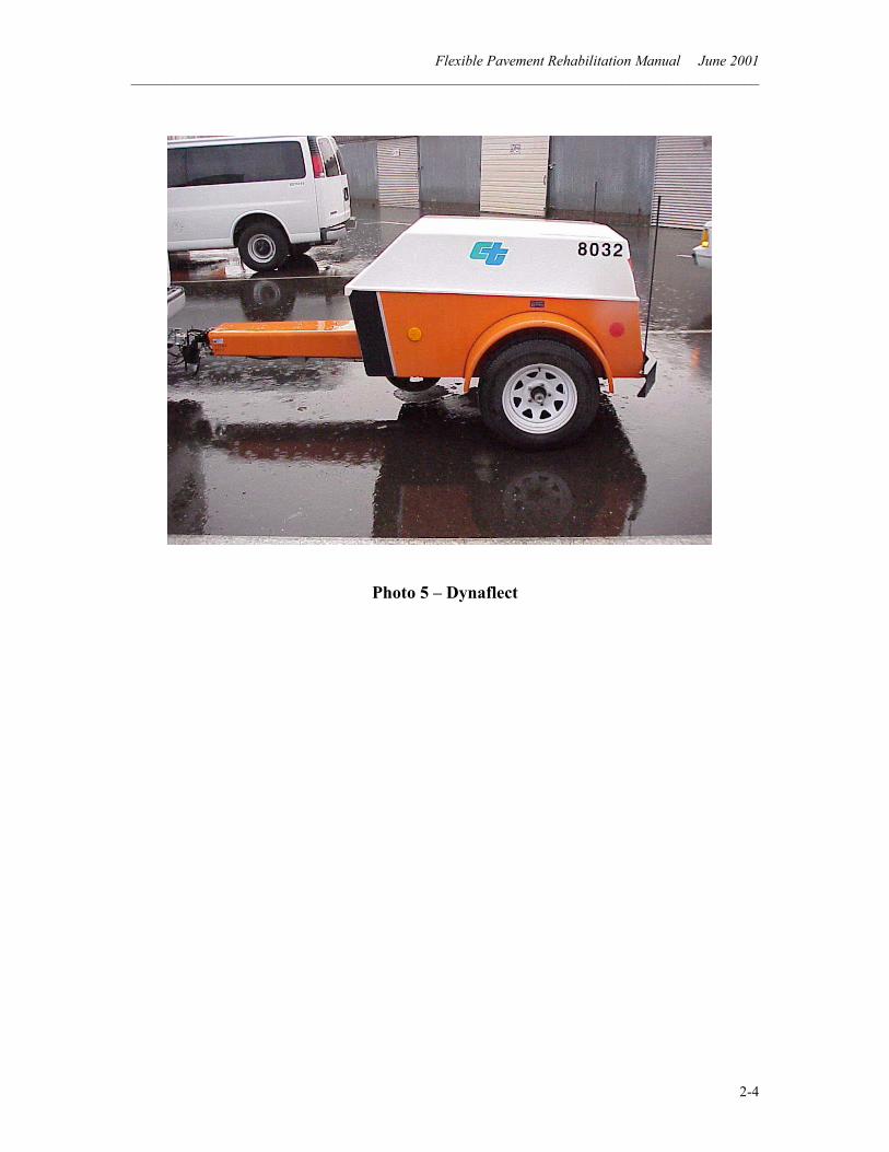
2 – 10 Equipment Since the early 1960’s, Caltrans research data have been based on deflections obtained by the "California Traveling Deflectometer” (2) (Photo 1). The trailer consisted of a mechanical arm that placed the probe between the dual wheels on a single rear axle. The dual wheels were reconfigured so that the probe was easy to insert. The probe measured the vertical movement (deflection) of the pavement as the dual wheels passed the site. The Traveling California Deflectometer built by Caltrans, was one of a kind and operated for routine work until 1969 and for research until about 1980. After it was no longer practical to use the California Traveling Deflectometer due to the age of its electronics, the trailer portion was retained,) and used to apply loads to pavement measurement sites to perpetuate the standard deflection device. This is now referred to as the "California Deflectometer". A Benkelman Beam* (Photo 2) is used to measure the deflection at the site. Either the California Traveling Deflectometer or the California Deflectometer were used in the development of Caltrans’ flexible pavement overlay design method and all past research projects. The California Deflectometer is currently used to correlate other deflection devices such as the falling weight deflectometer (Photos 3 and 4) and Dynaflect (Photo 5). Correlation is
done at least annually. For routine deflection measurements since 1969 Caltrans has been using the Dynaflect. For engineers and agencies outside Caltrans using this design method, consideration should be given to correlating testing equipment with a truck having the axle weight, tire spacing, and tire pressure that conforms to the specifications of the California Deflectometer. (See California Test 356).
Flexible Pavement Rehabilitation Manual June 2001 ______________________________________________________________________________________
2-2
Photo 1 – California Traveling Deflectometer
Photo 2 - Benkelman Beam
Photo courtesy of Roger Smith
Flexible Pavement Rehabilitation Manual June 2001 ______________________________________________________________________________________
2-3
Photo 3 - KUAB Falling Weight Deflectometer
Photo 4 – JILS Falling Weight Deflectometer
Flexible Pavement Rehabilitation Manual June 2001 ______________________________________________________________________________________
2-4
Photo 5 – Dynaflect
Flexible Pavement Rehabilitation Manual June 2001 ______________________________________________________________________________________
2-5
2 – 20 Establishing Test Sections
Test sections are representative portions of a roadway being considered for rehabilitation. They are selected as being representative of the entire mile, which helps to keep the amount of preliminary survey work to a reasonable level on projects that are several miles long.
Traffic safety should always be considered when selecting test sections. Areas of inadequate sight distance should be avoided. The district coordinator or area maintenance superintendent should be contacted for assistance and for traffic control.
For two-lane highways, if the project is less than a mile in length, the entire project is considered the test section. Pavement deflections are measured at approximately 0.01-mile (0.02-km) intervals in the outside wheel path (OWP) in both lanes. When projects are greater than a mile in length, a 0.20-mile (0.32-km) test section (21 deflection readings at 0.01-mile intervals) is selected to represent each lane mile. If possible, test sections are staggered from lane to lane to obtain a representative coverage of the roadway.
For multi-lane highways if the project is less than a mile in length the entire project is considered the test section. Pavement deflections are measured at approximately 0.01-mile intervals in the outside wheel path in both outside lanes. If possible, at least one 0.20-mile test section* is selected for each of the inner lanes, with pavement deflections
* Normally, 0.20-mile test sections consist of 21 deflection readings at 0.01-mile intervals. The measurements are usually made in the outside wheel path or the location with the most distress.
measured in the OWP, wherever possible. Side clearance to fixed objects (i.e. guard railing) may make this unattainable.
If the multi-lane project is greater than a mile in length, a 0.20-mile test section should be selected for each mile for both outer lanes. For each five miles of roadway, one 0.20-mile test section should be selected for each of the inner lanes. Additional test sections will be required if structural section changes occur and/or roadway appearances are not uniform.
Pavement deflections should be measured from the beginning to the end on ramps or connectors using the whole as a test section. Short ramps require a short testing interval in order to obtain sufficient readings. Extremely long ramps testing may be longer than the normal 0.2-mile test section. If the ramp is closed to traffic when testing, the wheel path with the most distress should be used. Otherwise the wheel path that allows the traffic to pass safely is tested. Shoulders that will carry future traffic should have test sections established according to the normal procedure in this section. Sometimes state highways are also city streets. Test section determinations on city streets are performed in the same manner as described for two-lane roadways and multilane facilities. It is often necessary to select a greater number of test sections on city streets or test continuously due to frequent changes in structural section and/or roadway condition.
Engineering judgment should always be used in selecting the number of test sites
Flexible Pavement Rehabilitation Manual June 2001 ______________________________________________________________________________________
2-6
for pavement deflection measurements. The suggested test frequencies described above are the minimum number recommended. Structural section changes are not always clearly visible in the field, but can usually be located from large changes in deflection measurements and confirmed by core data. Therefore, whenever there appears to be a need for additional information, make as many deflection measurements as necessary.
As the need for additional lanes has occurred, widening of the roadway has sometimes created two different structural sections even within a single lane. These can usually be noticed by a longitudinal crack at the joint. A test section on each of the structural sections should be selected for use in the rehabilitation study.
Occasionally, a return to a project may be required for additional testing after reviewing the initial deflection data in the office.
2 – 30 Pavement Background Information
Background information is obtained from both the Region/District and the files of the Structural Section Design and Rehabilitation (SSD&R) Branch, Office of Materials Engineering and Testing Services.
When requesting a pavement deflection study from SSD&R, the District Materials Engineer (DME) should provide at least the following information: the original structural section data, maintenance overlays and
date of placement, and the project’s design Traffic Index (TI).
SSD&R has records on previous deflection studies. If the District’s records show no maintenance or rehabilitation was done for the project in question, the previous structural section data may be used. If information is limited or not available, pavement cores must be removed to provide this information.
Previous deflection studies for the project found in the SSD&R files, where no maintenance or rehabilitation has been done, can be used to determine a rate-of-change in deflections that may be considered when designing new rehabilitation strategies. Normally, deflections increase with age beginning several months after construction if the pavement is under traffic loads.
A previous study may have been done when moisture was in the structural section. Consequently, those deflections may be higher than in the current study. If this happens, the previous, higher deflections should be used to design the current rehabilitation.
2 – 40 Collecting Field Data
A pavement condition inspection is as important to the design engineer as the deflection values. The function of the pavement condition inspection is to obtain the necessary information to be used in conjunction with the evaluated deflection values to determine the appropriate rehabilitation strategies.
The pavement condition inspection provides data that may convince the
Flexible Pavement Rehabilitation Manual June 2001 ______________________________________________________________________________________
2-7
designer to adjust the rehabilitation to meet the special requirements of that section of pavement.
The inspection of the project should describe the general condition of the pavement in terms of visual appearance including the type, severity and extent of distress. This should include items such as rutting, bleeding, raveling, patching, potholes, shoving (sometimes called slippage), corrugations, pumping, delamination, and the various types of cracking.
Also, an inspection of the project should include other details that should be recorded such as the existing structural section changes; permanent vertical control features that will limit an increase in profile grade; any localized drainage problems; embankment settlement; and areas of deep cuts and fills within the test section. Representative test sections and other important features recorded, such as failed areas whether tested or not tested should be photographed and recorded. Air and pavement temperatures should be measured. Date and time of measurement should be recorded.
2 – 50 Measuring Deflections
California Test 356 should be consulted when pavement deflection measurements will be obtained with different testing devices (4). A copy of the test method can be downloaded from the following Caltrans’ Internet address: (Address as of June 2001)
www.dot.ca.gov/hq/esc/ctms/index.html
2 – 60 Converting to Equivalent Deflectometer Values Caltrans, at the present time, uses the Dynaflect as its primary deflection-measuring device. Although repeatable instruments, each Dynaflect has a unique correlation curve. The correlation curve for each Dynaflect vs. California Deflectometer has been determined, through experience and testing, to be non-linear and unique. SSD&R has a conversion chart for each of its Dynaflects to be used to convert each individual deflection measurement to the equivalent California Deflectometer.
When using the falling weight deflectometer, convert the mean and 80th percentile deflection values to equivalent California Deflectometer values using appropriate correlation curves.
A comparison of each deflection-measuring device to the California Deflectometer should be performed at least once a year. The correlation curve results can be calculated and placed in a conversion chart for ease of use.
2 - 70 Mean and 80th Percentile Deflections Individual deflection readings for each test section should be reviewed prior to determining mean and 80th percentile values. This review may locate possible areas that are not representative of the entire test section.
An example would be a localized failure with a very high deflection. It may be more cost effective to repair the various failed sections prior to rehabilitation Thus, the high deflection values in the repaired areas would not be included
Flexible Pavement Rehabilitation Manual June 2001 ______________________________________________________________________________________
2-8
when calculating mean and 80th percentile values for the representative test sections.
When similar deflection values are found within a test section they should be analyzed as a group. There may be several groups within the test section or only one. If all deflections are similar, the entire test section is analyzed as a whole. With this in mind, engineering judgment must always be utilized in analyzing deflection data.
The mean deflection level for a test section is determined by dividing the number of individual deflection measurements into the sum of the deflections.
x = nDi∑
Where:
x = mean deflection for a test section Di = an individual deflection
measurement in the test section n = number of measurements in the
test section
The 80th percentile deflection value represents a deflection level at which approximately 80 percent of all deflections are less than the calculated value and 20 percent are greater than the value. Thus the design will provide thicker rehabilitation than using the mean value. The 80th percentile deflection values are obtained using the following equation:
sxD 84.080 +=
Where:
x = mean deflection for a test section D80 = 80th percentile of the
deflections at the surface for a test section, in inches
s = standard deviation of all test
points for a test section
( )1
2
−−∑
=n
xDs i
Flexible Pavement Rehabilitation Manual June 2001 ______________________________________________________________________________________
2-9
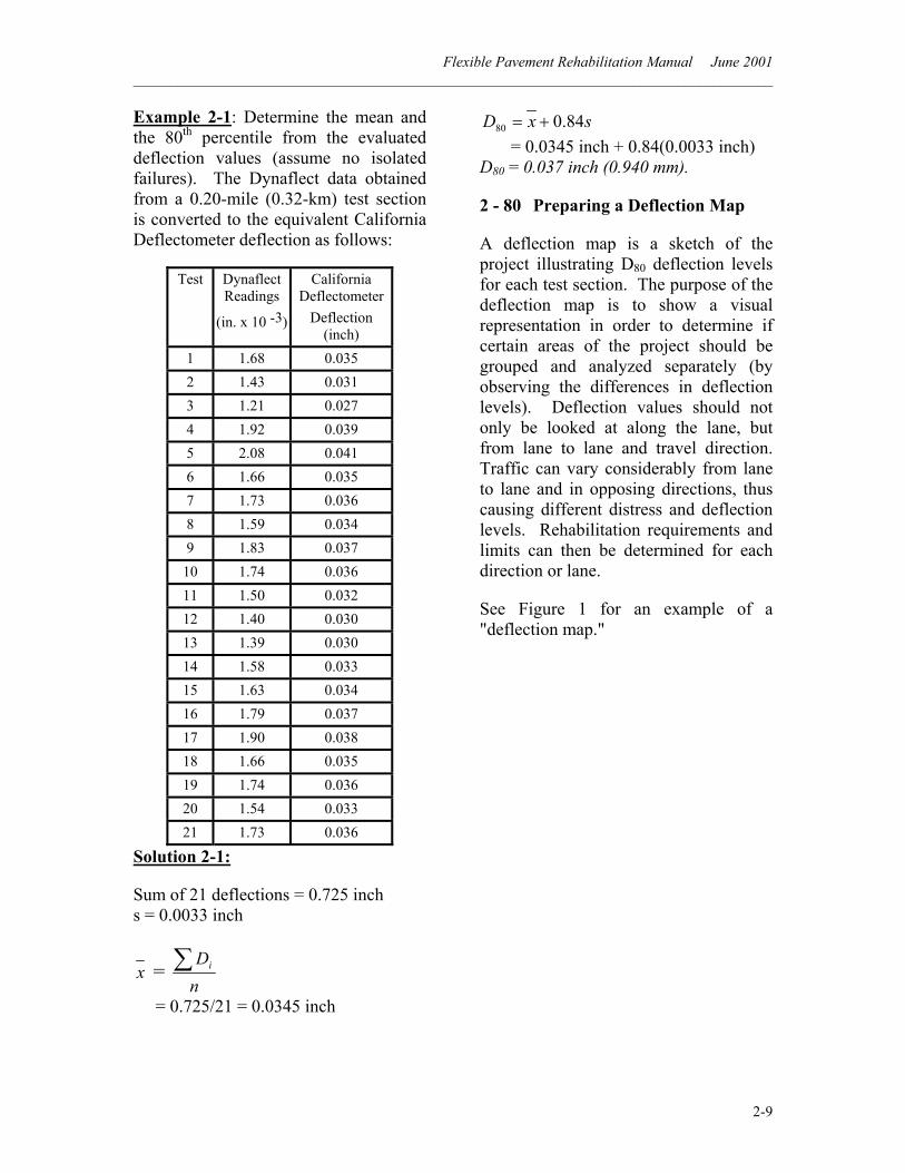
Example 2-1: Determine the mean and the 80th percentile from the evaluated deflection values (assume no isolated failures). The Dynaflect data obtained from a 0.20-mile (0.32-km) test section is converted to the equivalent California Deflectometer deflection as follows:
Test
Dynaflect Readings
(in. x 10 -3)
California Deflectometer
Deflection (inch)
1 1.68 0.035 2 1.43 0.031 3 1.21 0.027 4 1.92 0.039 5 2.08 0.041 6 1.66 0.035 7 1.73 0.036 8 1.59 0.034 9 1.83 0.037
10 1.74 0.036 11 1.50 0.032 12 1.40 0.030 13 1.39 0.030 14 1.58 0.033 15 1.63 0.034 16 1.79 0.037 17 1.90 0.038 18 1.66 0.035 19 1.74 0.036 20 1.54 0.033 21 1.73 0.036
Solution 2-1:
Sum of 21 deflections = 0.725 inch s = 0.0033 inch
x = nDi∑
= 0.725/21 = 0.0345 inch
sxD 84.080 += = 0.0345 inch + 0.84(0.0033 inch) D80 = 0.037 inch (0.940 mm).
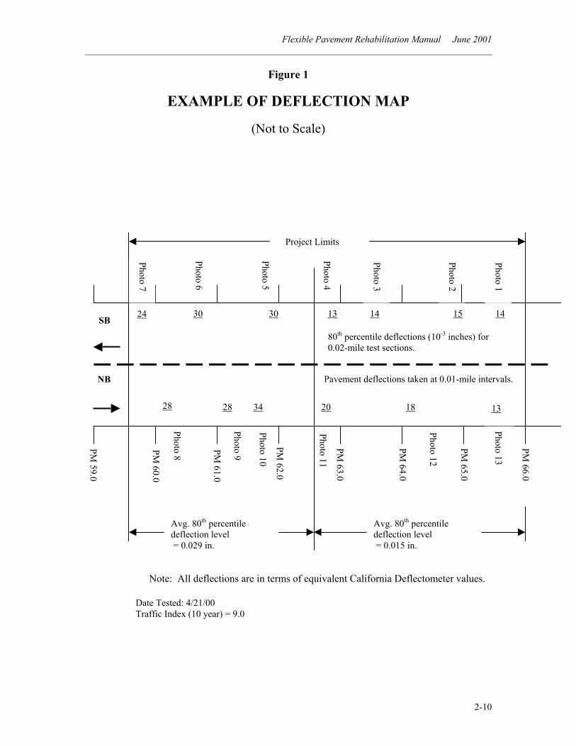
2 - 80 Preparing a Deflection Map
A deflection map is a sketch of the project illustrating D80 deflection levels for each test section. The purpose of the deflection map is to show a visual representation in order to determine if certain areas of the project should be grouped and analyzed separately (by observing the differences in deflection levels). Deflection values should not only be looked at along the lane, but from lane to lane and travel direction. Traffic can vary considerably from lane to lane and in opposing directions, thus causing different distress and deflection levels. Rehabilitation requirements and limits can then be determined for each direction or lane.
See Figure 1 for an example of a "deflection map."
Flexible Pavement Rehabilitation Manual June 2001 ______________________________________________________________________________________
2-10
Figure 1
EXAMPLE OF DEFLECTION MAP
(Not to Scale)
Project Limits
Avg. 80th percentile deflection level = 0.029 in.
Avg. 80th percentile deflection level = 0.015 in.
Date Tested: 4/21/00 Traffic Index (10 year) = 9.0
Note: All deflections are in terms of equivalent California Deflectometer values.
PM 59.0
PM 60.0
PM 61.0
PM 62.0
PM 63.0
PM 64.0
PM 65.0
PM 66.0
24
28
30 30
28 34
13
20 18 13
14 15 14
NB
SB
Photo 1
Photo 2
Photo 3
Photo 4
Photo 5
Photo 6
Photo 7
Photo 13
Photo 12
Photo 10
Photo 9
Photo 8
Photo 11
80th percentile deflections (10-3 inches) for 0.02-mile test sections.
Pavement deflections taken at 0.01-mile intervals.
Flexible Pavement Rehabilitation Manual June 2001 ______________________________________________________________________________________
3-1
CHAPTER 3
INTRODUCTION TO
AC PAVEMENT REHABILITATION DESIGN
Currently, Caltrans uses the philosophy of extending service life of a pavement for a 10-year period of time for rehabilitation. However, the design engineer may request pavement rehabilitation for a different design period. The design procedure is the same for a different design period. It is accomplished by using the appropriate Traffic Index (TI) for the period of time for the design.
When determining the rehabilitation alternatives, the engineer must know both the design period requested and the TI for the pavement being evaluated. Traffic Index is a measure of the number of equivalent 18,000-lb (80-kN) single axle loads (ESAL’s) expected in the design lane over the design period. The TI does not vary directly with ESAL’s but rather exponentially according to the following formula as illustrated in Table 603.4A of the “Highway Design Manual.” (8)
TI = 9.0 (ESAL / 106 ) 0.119
Where: TI = Traffic Index ESAL = Equivalent 18,000-lb Single Axle Loads
If that TI is unknown and the 10-year TI is known, use Table 603.4A in the HDM to establish the ESAL’s. Then proportion from the ten-year ESAL to the ESAL of the new design life. Finally
select the corresponding TI for the new ESAL.
There are three components to be considered when designing flexible pavement rehabilitation:
1) Structural adequacy upgrade; 2) Reflective crack retardation; and 3) Ride quality improvement.
3 - 10 Designing for Structural Adequacy
Deflections are used for determining the thickness requirements for rehabilitation of asphalt concrete (AC) pavements when considering structural section adequacy. Condition and structural section of the existing roadbed together with measured deflections and the projected TI provide the majority of the information to be used during consideration for structural adequacy.
Once the data has been collected and the deflections of the test sections have been reduced to 80th percentile deflections (D80’s) and placed on a project deflection map, the design process involves both calculations and engineering judgment.
The project deflection map should be examined for similar D80 values. Adjacent test sections with similar D80 values should be grouped together. There may be several groups within the project or only one. If all D80 values are similar, the entire project may be analyzed as a whole.
A group is a collection of adjacent test sections that have similar values for the:
• Average 80th percentile deflection (D80).
Flexible Pavement Rehabilitation Manual June 2001 ______________________________________________________________________________________
3-2
• Average existing asphalt concrete pavement thickness.
• Type of base.
• Traffic Index (TI).
Each of these has an influence on the rehabilitation.
Test sections should not be grouped together if the existing AC thickness varies more than 0.10 ft (30 mm), the type of base materials is different, or the TI is different. These influence the tolerable deflection level that is used in determining the rehabilitation. Similar groups of test sections can be analyzed together.
D80 values should not be examined only along the lane, but should be examined from lane to lane and in the direction of travel. Traffic may vary considerably from lane to lane and in opposing directions, thus causing different distress and deflection levels. Rehabilitation requirements and limitations should be considered for each direction or lane as is appropriate from the data and to meet the needs of the project site.
Suggestion:
In selecting groups of similar D80 values, it is suggested that only adjacent test sections with D80 values that differ less than about 0.010 inch (0.254 mm) should be grouped together. More than 0.010-inch difference will most likely produce different thickness requirements.
Once groups with similar D80 values, structural sections, types of bases and TI’s have been identified; average the D80 values for each group. Use the TI,
average existing AC pavement thickness and type of base to determine the tolerable deflection at the surface (TDS) for the group using Table 1 (Chapter 6).
For existing AC pavement over untreated base material such as aggregate base (AB), native material, etc., use the TDS corresponding to the thickness of the existing AC pavement and the appropriate TI.
For existing AC pavement over treated base or portland cement concrete (PCC), use the TDS values in the row for CTB and the column for appropriate TI. However, if the underlying CTB thickness is less that 0.35 ft (105 mm), consider it an untreated base and determine the TDS from the upper part of the table corresponding to the thickness of the existing AC pavement and the appropriate TI.
In locations where existing AC pavement is over a treated base and the measured deflections are high, the treated base may not be performing as it should. The treated base layer is no longer carrying the load as it was originally designed to do. It may have deteriorated to the point where this layer is acting more like an untreated base. In this case, the rehabilitation should be designed as though the existing structural section is AC over untreated base.
Choosing the appropriate existing structural section interaction – AC over treated base or AC over untreated base – should be made carefully. This choice will greatly influence the TDS, and the resulting thickness of rehabilitation strategies.
Flexible Pavement Rehabilitation Manual June 2001 ______________________________________________________________________________________
3-3
Suggestion:
When the D80 value for deflections of a test section of AC pavement over treated bases is greater than 0.014 inch, the rehabilitation may be designed as though the existing structural section is AC over untreated base.
Engineering judgment is required when trying to determine if the treated base is performing satisfactorily. Besides deflections, the condition of the pavement surface should be considered. The greater the amount of alligator cracking, the more likely the treated base layer is not carrying the load as originally designed. But, if the distress is mainly transverse cracks without alligator cracking and localized failures, the treated base is probably still intact even though the D80 value is greater than 0.014 inch. D80 values of as high as 0.020 inch have been measured over intact treated base.
Occasionally on an older pavement, only minimal distress is apparent from the condition survey and the average D80 is less than the TDS. In this case, corrective repair may not be necessary other than a seal coat that will seal cracks, improve appearance, delay oxidation of the asphalt concrete and prolong the pavement life.
If the average D80 is greater than the TDS, determine the required percent reduction in deflection at the surface (PRD) to restore structural adequacy as follows:
PRD = ( )10080
80
AverageDTDSAverageD −
Where:
PRD = Percent Reduction in Deflection Required at the surface, as percent
TDS = Tolerable Deflection at the Surface, in inches
D80 = 80th Percentile of the Deflections at the surface for a test section in inches
In Caltrans, structural section design is based on the concept of gravel equivalence. This same concept is used in flexible pavement rehabilitation.
For rehabilitation, the additional gravel equivalence (GE) required is determined from the calculated percent reduction in deflection and Table 2. It is the amount of AS gravel that will provide sufficient strength to reduce the deflections to the tolerable level.
A gravel factor (Gf) expresses the relative value of various materials when compared to gravel. The gravel factor (Gf) is given to a material that, when divided into the gravel equivalence required, will provide the layer thickness of the material.
Note that for new pavement design the Gf for asphalt concrete varies with the TI [Table 608.4, of the Highway Design Manual]. However, for most types of rehabilitation (overlay design being one), the Gf has been established at 1.9 for all Traffic Indices.
Flexible Pavement Rehabilitation Manual June 2001 ______________________________________________________________________________________
3-4
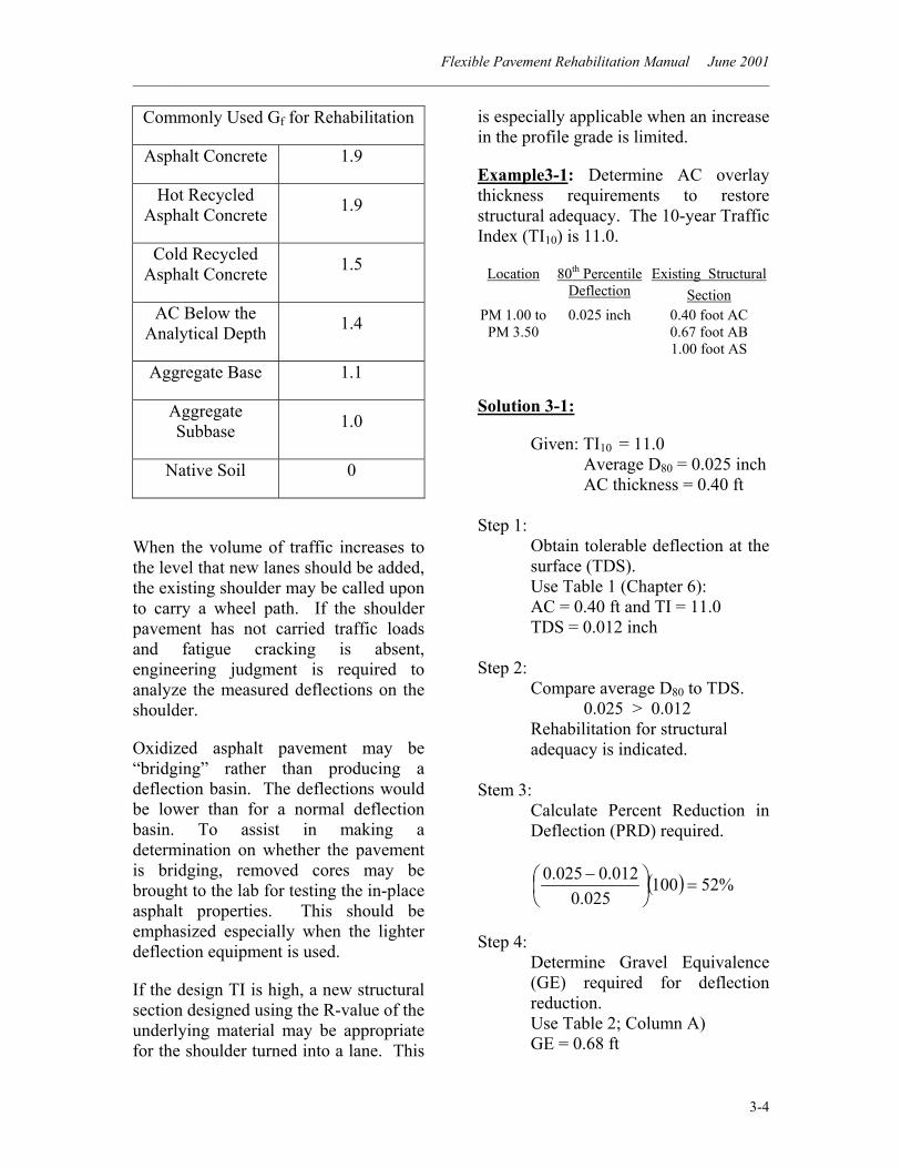
Commonly Used Gf for Rehabilitation
Asphalt Concrete 1.9
Hot Recycled Asphalt Concrete 1.9
Cold Recycled Asphalt Concrete 1.5
AC Below the Analytical Depth 1.4
Aggregate Base 1.1
Aggregate Subbase 1.0
Native Soil 0
When the volume of traffic increases to the level that new lanes should be added, the existing shoulder may be called upon to carry a wheel path. If the shoulder pavement has not carried traffic loads and fatigue cracking is absent, engineering judgment is required to analyze the measured deflections on the shoulder.
Oxidized asphalt pavement may be “bridging” rather than producing a deflection basin. The deflections would be lower than for a normal deflection basin. To assist in making a determination on whether the pavement is bridging, removed cores may be brought to the lab for testing the in-place asphalt properties. This should be emphasized especially when the lighter deflection equipment is used.
If the design TI is high, a new structural section designed using the R-value of the underlying material may be appropriate for the shoulder turned into a lane. This
is especially applicable when an increase in the profile grade is limited.
Example3-1: Determine AC overlay thickness requirements to restore structural adequacy. The 10-year Traffic Index (TI10) is 11.0.
Location 80th Percentile Deflection
Existing Structural Section
PM 1.00 to PM 3.50
0.025 inch 0.40 foot AC 0.67 foot AB 1.00 foot AS
Solution 3-1:
Given: TI10 = 11.0 Average D80 = 0.025 inch AC thickness = 0.40 ft Step 1:
Obtain tolerable deflection at the surface (TDS). Use Table 1 (Chapter 6): AC = 0.40 ft and TI = 11.0 TDS = 0.012 inch
Step 2: Compare average D80 to TDS. 0.025 > 0.012 Rehabilitation for structural adequacy is indicated.
Stem 3: Calculate Percent Reduction in Deflection (PRD) required.
( ) %52100025.0
012.0025.0=
−
Step 4:
Determine Gravel Equivalence (GE) required for deflection reduction. Use Table 2; Column A) GE = 0.68 ft
Flexible Pavement Rehabilitation Manual June 2001 ______________________________________________________________________________________
3-5
Step 5: Determine the required thickness of AC overlay.
ftGGEOverlay
f36.0
9.168.0
===
Round to 0.35 ft (105 mm).
Recommendation: 0.35-ft (105-mm) overlay of DGAC.
3 - 20 Design Governed by Reflective Cracking
Reflective crack retardation of the new overlay needs to be considered. Retarding the propagation of cracks from the existing pavement into the new AC overlay will extend its service life.
For AC pavements over untreated bases, the thickness of a new DGAC overlay should be at least half the thickness of the existing asphalt concrete up to a maximum of 0.35 ft (105 mm). Or, if the existing AC pavement is to be milled, the thickness of the new AC should be half the thickness of the remaining pavement up to a maximum of 0.35 ft.
For AC pavements over a treated base or PCC the general guideline (exceptions will occur) for a ten-year design is a minimum overlay of 0.35 ft (105 mm) of new dense graded asphalt concrete (DGAC). This was developed by experience and is usually adequate for retarding reflective cracks. An exception might be when the underlying material is a thick PCC such as on an overlaid PCC freeway that was not cracked and seated. In this case a
minimum thickness of 0.45 ft. (135 mm) may be appropriate.
For a design life different from a 10-year design, a slight modification changes the thickness. For a five-year design, experience has determined the thickness should be approximately 75 percent of the ten-year design thickness. For a twenty-year design, use 125 percent.
As always, exceptions will occur and engineering judgment will be necessary for final design. Factors to be considered that might influence the engineer to increase the thickness are: (1) Type, sizes, and amounts of surface
cracks.
(2) Extent of localized failures.
(3) Existing structural section material and age.
(4) Thickness and performance of previous rehabilitation.
(5) Environmental factors.
(6) Anticipated future traffic loads (Traffic Index).
Unfortunately, there are no set criteria that will aid the engineer in the decision process in regards to designing to prevent reflective cracking. Experience with similar roadways repaired in the general area; past overlays and their performance; and discussions with local maintenance and construction personnel are all part of the data gathered to be considered in the final decision and engineering judgment process.
Flexible Pavement Rehabilitation Manual June 2001 ______________________________________________________________________________________
3-6
3 - 30 Design Governed by Ride Quality
The Pavement Management System records ride quality as part of their pavement condition inventory. The International Roughness Index (IRI) for each lane is measured for the Pavement Condition Survey. (IRI has replaced the Ride Score. The Ride Score of 45 or more will “trigger” a project. The equivalent IRI is not yet determined.) When ride quality measurements indicate that the pavement needs improvement, procedures are needed to smooth the pavement. At least two options emerge as viable solutions:
(1) Place an asphalt concrete overlay thick enough to be placed in two lifts [0.25-ft (75-mm) minimum].
(2) Cold plane the existing pavement prior to placing the new asphalt concrete.
Ride quality will ultimately govern the rehabilitation strategy design if the requirements for structural adequacy and reflective crack retardation are less than 0.25 ft (75 mm).
Please note that if the two-lift option is chosen, the July 1999 Standard Specification Section 39–6.01(9) gives the contractor the option to place 0.25 ft (75 mm) in one layer. Any rehabilitation report that recommends this overlay thickness for improving the ride quality, should point out in the report that the overlay needs to be placed in two layers and specified as such in the project special provisions.
3 - 40 Choosing the Design Recommendation
The final choice of the recommended rehabilitation alternative is based on choosing a strategy that will provide a total structural section thickness that is adequate to resist the anticipated loading it will experience throughout its design period, the potential for reflective cracking and to improve ride. Once the rehabilitation strategies have been determined to correct for lack of structural adequacy, to retard reflective cracking and to improve ride quality, a single strategy must be chosen which will be sufficient for all three conditions. In addition to choosing a rehabilitation strategy to correct the three criteria listed earlier, constructability concerns must be addressed. Prior to placement of asphalt concrete on an existing pavement, some preparation is required besides what is specified in Standard Specifications 39-4.01. Cracks wider than 0.25 inch (5 mm) should be sealed; loose and/or spalling pavement removed; and potholes and localized failures repaired. Routing cracks before applying crack sealant has been found to be beneficial. The width of the routing should be 0.25 inch (5 mm) wider than the crack width. The depth should be equal to the width of the routing plus 0.25 inch (5 mm). In order to alleviate the potential bump in the overlay from the crack sealant, leave the crack sealant 0.25 inch (5 mm) below grade to allow for expansion. Design recommendations should include a reminder of these preparations. It has been found that during construction a dense graded AC layer of less than 45 mm (0.15 ft) may cool
Flexible Pavement Rehabilitation Manual June 2001 ______________________________________________________________________________________
3-7
considerably before adequate compaction occurs. Therefore, for a surface course for rehabilitation, Caltrans generally uses a minimum thickness of 45 mm (0.15 ft). The minimum thickness for rubberized AC is 30 mm (0.10 ft) since it is placed at a higher temperature. Structural Section Design and Rehabilitation Branch (SSD&R) designs asphalt concrete thicknesses in 0.05-ft increments. With the change to metric values, SSD&R increases the thicknesses by 15 mm for each 0.05-ft increment (Table 5). Please note that this is not an exact mathematical conversion. Example3-2: Determine the AC rehabilitation requirements. The 10-year Traffic Index (TI10) is 11.0. There are no restrictions on an increase in profile grade.
Location 80th Percentile
Deflection Existing Structural
Section PM 1.00 to
PM 3.50 0.025 inch 0.40 foot AC
0.67 foot AB 1.00 foot AS
Solution 3-2:
Recommendations to be considered: Structural Adequacy:
A 0.35-ft DGAC overlay. Refer to Example 3-1. (Rubber AC alternatives are discussed in Section 4-20 of this manual.)
Reflective Cracking: A 0.20-ft DGAC overlay. (One-half existing AC thickness.)
Ride Quality: A 0.25-ft DGAC overlay placed in two layers. (Section 3-30).
Discussion 3-2: • A second option for ride quality is to
mill the existing rough pavement to remove much of the surface undulations prior to placing the new AC overlay. Milling off 0.10 to 0.20 ft (30 to 60 mm) will usually be sufficient. Milling will change D80 and require additional design calculations.
• Cold planing and replacing the
existing surface with DGAC or hot recycled AC to the same grade would provide a good solution for reflective cracking and ride quality. (This is discussed in Section 4-50 of this manual.)
• A 0.35-ft DGAC overlay may
increase the profile grade beyond the allowable if there are restraints such as are found in urban areas.
Recommendation 3-2: 0.35-ft (105-mm) overlay of DGAC.
Flexible Pavement Rehabilitation Manual June 2001 ______________________________________________________________________________________
4-1
CHAPTER 4
FLEXIBLE PAVEMENT REHABILITATION DESIGN
GUIDE 4 – 10 Basic Overlay Using DGAC See Chapter 3 for a complete discussion of Basic Overlay design using dense graded asphalt concrete. Dynaflect deflection values (Caltrans primary deflection device) converted to equivalent California Deflectometer values are used for determination of overlay thickness. 1. Calculate Mean *
x = nDi∑
2. Calculate Standard Deviation**
( )1
2
−−∑
=n
xDs i
where:
x = mean deflection for a test section
80D = 80th percentile of the
deflections at the surface for a test section in inches
* When determining the Mean, omit any individual measurements on isolated failures since recommendations in the report will be to replace these failures. ** ( )xDi − is the difference between each individual measurement and the mean value. The number of measurements is designated n.
s = standard deviation of all
deflections for a test section
iD = an individual deflection measurement in the test section
n = number of measurements in the
test section 3. Calculate the 80th percentile sxD 84.080 += 4. Determine the Tolerable Deflection at the Surface (TDS).
Determine the TDS from the Tolerable Deflection Chart (Table 1) with the design Traffic Index (TI) and either the thickness of the existing asphalt concrete (AC) pavement or the type of base data. If D80 is at or below the TDS, then the pavement is considered structurally adequate and any overlay thickness should be based on reflective crack retardation and/or ride score reduction. If D80 is greater than the TDS, then the overlay required for structural adequacy is determined along with the need for reflective crack retardation and/or ride score reduction. 5. Calculate the Percent Reduction in Deflection at the surface:
PRD = ( )10080
80
DTDSD −
Where: PRD = Percent Reduction in
Deflection required at the surface
Flexible Pavement Rehabilitation Manual June 2001 ______________________________________________________________________________________
4-2
TDS = Tolerable Deflection at the Surface, in inches
D80 = 80th Percentile of the Deflections at the Surface for a test section in inches. If test sections have been grouped, then average D80 for the group is used.
6. Determine the increase in Gravel Equivalence (GE) required to reduce D80 to the TDS. Utilizing the calculated PRD value, go to Table 2, Column A, to determine the GE. (Discussion of an AC overlay placed on a cushion course is in Section 4-70.) 7. Determine the Gravel Factor, Gf. For a dense graded asphalt concrete (DGAC) overlay over an existing AC pavement use a Gf of 1.9 regardless of thickness and TI. 8. Determine the overlay thickness for structural adequacy.
fGGEoverlay =
9. Determine the overlay thickness for reflective cracking.
overlay = A minimum of half of the existing AC thickness (Section 3-20)
10. Determine the overlay thickness for ride quality.
overlay = A minimum of 0.25 ft placed in two layers (Section 3-30)
Example 4-1: Determine the recommended AC overlay thickness for an existing AC pavement.
Ten-Year TI
80th Percentile Deflection
Existing Structural Section
10.0 0.030 inch 0.55 foot AC 0.50 foot AB 1.00 foot AS
Existing conditions: • Occasional to intermittent alligator,
transverse, and longitudinal cracks, (some 0.5 inch wide).
• Fairly smooth ride. Calculations 4-1:
Check for overlay thickness required for structural adequacy. Step 1:
Obtain tolerable deflection at the surface (TDS). Use Table 1: AC = 0.55 ft and TI = 10.0 TDS = 0.012 inch
Step 2: Compare average D80 to TDS. 0.030 > 0.012
Stem 3: Calculate Percent Reduction in Deflection required.
( ) %60100030.0
012.0030.0=
−
Step 4:
Determine Gravel Equivalence (GE) required for deflection reduction. Use Table 2; Column A GE = 0.85 ft
Flexible Pavement Rehabilitation Manual June 2001 ______________________________________________________________________________________
4-3
Step 5: Determine the required thickness of AC overlay for structural adequacy.
ftGGEOverlay
f45.0
9.185.0
===
Check for the overlay thickness required for reflective crack retardation. To retard reflective cracks entering the new overlay from the pavement below choose a thickness for the new overlay at least one-half the thickness of the existing AC pavement being overlaid (up to a maximum of 0.35 ft (105 mm) for an underlying aggregate base). Determine half of the existing pavement thickness:
overlay = 255.0 = 0.275 Round
to 0.30 ft. Check for smoothness. The ride quality was previously determined to be acceptable. If it were not acceptable, a 0.25-ft (75-mm) DGAC overlay would have to be placed in two layers. Discussion 4-1: • Since reflective cracking
requirement is less than 0.45 ft (135-mm), and since smoothness is satisfactory, structural adequacy governs the overlay design thickness.
• For this overlay example, reflective cracking could never control, since the structural requirement of 0.45 ft (135 mm) is already above the 0.35-ft (105-mm) maximum for reflection.
• In this example, if the structural
requirement had been less than 0.30 ft (90 mm) and the ride quality needed improvement, then reflective cracking would be the controlling criteria with a required overlay of 0.30-ft (90-mm).
• To make a rough-riding pavement
smoother by using a minimum of two procedures, a mill-and-replace procedure or a procedure that places an AC overlay in two layers must be used. The design of the overlay for ride consideration would be as follows:
Option 1 - The overlay must be thick enough to allow for two layers to be placed. The 0.45-ft (135-mm) DGAC overlay for structural adequacy will provide the two layers needed for improving the ride quality. Option 2 - Mill the existing rough pavement to remove much of the surface undulations prior to placing the new AC overlay. Milling off 0.10 to 0.20 ft (30 to 60 mm) will usually be sufficient. Milling will change D80 and require additional design calculations.
Recommendation 4-1: 0.45-ft (135-mm) overlay of DGAC.
Flexible Pavement Rehabilitation Manual June 2001 ______________________________________________________________________________________
4-4
4 – 20 Rubberized Asphalt Concrete (Type G) * Caltrans standard overlay design is a dense graded asphalt concrete overlay thickness that will improve the serviceability for the time frame specified, usually a ten-year period. From that design thickness an alternate design with a thickness of rubberized asphalt concrete, gap graded (RAC Type G) can be determined. A thickness equivalency of not more than 1:2 is given to the RAC Type G when compared to the dense graded asphalt concrete (DGAC) for structural adequacy or reflective crack retardation. The equivalencies are tabulated in Tables 3 and 4 Using RAC Type G instead of DGAC allows a lower profile grade and reduces the amount of asphalt concrete materials used. The minimum thickness for RAC Type G is 0.10 ft (30 mm). Until further research, the maximum thickness For RAC Type G is limited by stability to 0.20 ft (60 mm). If the design calls for a thicker overlay, then a DGAC layer may be placed prior to placing the RAC Type G. For example, if the design calls for a 0.55-ft (165-mm) DGAC overlay, a 0.15-ft (45-mm) layer of DGAC could be placed first. Then the 0.40-foot (120-mm) DGAC remaining can be replaced with 0.20-ft (60-mm) of RAC Type G placed as the top layer (Table 3).
* Data from field and laboratory studies were used to produce Caltrans internal memorandum “Asphalt Rubber Hot Mix – Gap Graded Thickness Determination Guide” dated March 19, 1992.
A Rubberized Stress Absorbing Membrane Interlayer (SAMI-R) may be used to provide some strength when placed under RAC Type G. For structural strength, a SAMI-R is considered to provide an equivalence of 0.05 ft (15 mm) of RAC Type G (Table 3). For reflective crack retardation from wide cracks, the SAMI-R is considered to provide either 0.05 ft (15 mm) when the underlying base is a treated material or 0.10 ft (30 mm) when the underlying base is an untreated material (Table 4). However, it should be noted that RAC Type G might not prevent cold weather cracking. A Fabric Stress Absorbing Membrane Interlayer (SAMI-F) is not to be used under RAC Type G because the high placement temperature of the RAC Type G is close to the melting temperature of the SAMI-F material. Just as with DGAC, prior to placement of RAC Type G on an existing pavement, some preparation is required. Cracks wider than 0.25 inch (5 mm) should be sealed, and potholes and localized failures repaired. It is undesirable to place RAC Type G in areas that will not allow surface water to drain. As an example, on a surface that is milled only on the traveled way and not on the shoulders, thus forming a “bathtub” section. To offset that situation, a combination of materials might fit the design; for example, place a layer of DGAC to the original grade prior to placing the RAC Type G, or mill the shoulders to slope for drainage.
Flexible Pavement Rehabilitation Manual June 2001 ______________________________________________________________________________________
4-5
4 – 30 Stress Absorbing Membrane Interlayers
Two types of Stress Absorbing Membrane Interlayers are used for rehabilitation: 1.) Rubberized (SAMI-R). 2.) Fabric (SAMI-F). Placing a rubberized stress absorbing membrane interlayer on a pavement consists of an application of asphalt-rubber binder on the surface followed with aggregate screenings that are pre-coated with paving asphalt. Placing a fabric stress absorbing membrane interlayer on a pavement consists of an application of asphalt binder on the surface followed with the fabric. The fabric is manufactured from polyester, polypropylene or polypropylene-nylon material that is non-woven and heat treated on one side. See Standard Specifications 39-4.03. SAMI’s are used to retard reflective cracks, prevent water intrusion, and in the case of SAMI-R, enhance structural strength (Table 3). Judgment is required when considering the use of SAMI’s. • Consideration should be given to
areas that may prohibit surface water from draining out the sides of the overlay, thus forming a “bathtub” section.
• Since SAMI’s act as a moisture
barrier, they should be used with caution in hot environments where they could prevent underlying moisture from evaporating.
Moisture trapped within the asphalt concrete, under wheel loads, may provide a means by which the asphalt would be washed off the aggregates. This action is called stripping. Some mixes are more susceptible to this action than others. When AC is to be placed in these types of locations the aggregates should be treated prior to mixing. A SAMI may be placed between layers of new asphalt concrete (AC), such as on a leveling course, or on the surface of an existing AC pavement. When placed on an existing AC pavement some preparation is required to prevent excess stress on the membrane. This includes sealing cracks wider than 0.25 inch (5 mm), and repairing potholes and localized failures. SAMI-R: Placed Under Rubberized Asphalt Concrete Structural Strength – A SAMI-R also may be used to provide some structural strength when placed under an RAC Type G overlay that is designed for structural adequacy. The SAMI-R in this case is considered to be approximately 0.05 ft (15 mm) of RAC Type G for structural strength (Table 3). Reflective Cracking – A SAMI-R is considered to be equivalent to 0.05 ft (15 mm) of RAC Type G when the underlying base of the structural section is a treated base. When the underlying base is an untreated base, a SAMI-R is equivalent to 0.10 ft (30 mm) of an RAC Type G (Table 4).
Flexible Pavement Rehabilitation Manual June 2001 ______________________________________________________________________________________
4-6
Placed Under Non-Rubberized Asphalt Concrete When a SAMI-R is placed under non-rubberized asphalt concrete designed for reflective crack retardation, the equivalence of a SAMI-R depends upon the type of base material under the existing pavement. When the base is a treated material, a SAMI-R placed under DGAC or open graded asphalt concrete (OGAC) is considered to be equivalent to 0.10 ft (30 mm) of DGAC. When the base is an untreated material SAMI-R is equivalent to 0.15 ft (45 mm) of DGAC. SAMI-F: A Fabric Stress Absorbing Membrane Interlayer (SAMI-F), also called pavement reinforcing fabric (PRF), placed under DGAC designed for reflective crack retardation provides the equivalent of 0.10 ft (30 mm) of DGAC. This allows the project engineer to decrease the new profile grade and also save asphalt concrete materials. If the road to be rehabilitated has a high proportion of small radius horizontal curves, the use of SAMI-F is probably not cost effective due to the extra labor involved during placement.
A SAMI-F should not be placed directly on coarse surfaces such as a chip seal, OGAC, areas of numerous rough patches or on a pavement that has been cold planed. Coarse surfaces may penetrate the fabric and/or the paving asphalt binder used to saturate the fabric may be “lost” in the voids or valleys leaving areas of the fabric dry. For the SAMI-F to be effective in these areas, use a
leveling course of DGAC prior to the placement of the SAMI-F. Saturating the fabric with asphalt enhances the properties of the pavement reinforcing fabric. The fabric is placed on the asphalt concrete pavement that has had a heavy tack coat of asphalt applied. However, on a cool day the tack coat may cool rapidly, until it reaches the temperature of the pavement. In this case, the tack asphalt usually will remain tacky enough to hold the fabric in place, but full saturation will not occur. Therefore, it is up to the heat of the asphalt concrete overlay to re-melt the tack coat, allowing it to infiltrate the fabric. With normal heat and rolling pressure of the first layer of asphalt concrete, the fabric should become saturated. On warm days, the fabric may come close to full saturation just by lying on the asphalt tack coat because the asphalt stays liquid longer. SAMI-F’s have been found to be ineffective: 1.) When placed under asphalt rubber-asphalt concrete. This is due to the high placement temperature of the RAC Type G mix, which is close to the melting temperature of the fabric. 2.) For providing added structural strength when placed in combination with DGAC. 3.) In the reduction of thermal cracking of the new AC pavement overlay. 4 – 40 Cold Recycled Asphalt Concrete Pavement Assembly Bill (AB 1306) encourages State agencies to use more recycled materials in road construction and repairs. Caltrans Deputy Directive DD-
Flexible Pavement Rehabilitation Manual June 2001 ______________________________________________________________________________________
4-7
17 policy statement, effective November 11, 1993, directs the Department to recycle asphalt concrete whenever feasible. Consideration should be given on every project to recycle asphalt concrete (AC) used in highway construction, maintenance, and rehabilitation projects utilizing the Department’s priority hierarchy (see DD-17). Public and employee health and safety are not to be compromised by recycling AC on any project. To be economical on rehabilitation projects, a minimum of 10,000 tons (9070 tonnes) of AC material should be available for the recycle process. In the future, calculations using the then current price of asphalt material may change the quantity for the minimum tons to be economical.
Since this design method uses two procedures (milling and replacement), it can be considered appropriate to smooth a rough pavement.
Candidates for cold recycling are pavements whose asphalt content is uniform. The existence of heavy crack-sealant, numerous patches, open-graded asphalt concrete, and heavy seal coats make the new Cold Recycled Asphalt Concrete (CRAC) mix design inconsistent. Mix properties are more difficult to control. To avoid this problem when it occurs and still use this recycle option, a minimum of 0.08 ft (25 mm) should be milled off prior to the cold recycling operation. Light crack sealing (less than 5 % of the pavement) or a uniform single seal coat will not influence the design sufficiently to require removal. Caltrans has established a minimum mill depth of 0.15 ft (45 mm) for cold recycling. Since existing pavement
thicknesses will have slight variations, the cold recycling design should leave at least the bottom 0.15 ft (45 mm) of the existing AC pavement in place. This is to insure the milling machine does not loosen base material and possibly contaminate the CRAC mix design. Traffic constraints may make CRAC impractical since traffic is not allowed on the lane being recycled until the process is completed and the recycled material is compacted. The recycling process consists of the following: 1. Mill the existing AC pavement to the
designed depth. 2. Mix the milled material with an oil
or rejuvenating agent and leave in a windrow.
3. The CRAC material is then spread with a paving machine and compacted.
The surface of the CRAC material has a low resistance to abrasion. Therefore, all CRAC material must be covered with a minimum thickness of 0.15 ft (45 mm) DGAC for a wearing surface after a short period of time after the recycling process. When designing the CRAC for structural adequacy, the Tolerable Deflection at the Surface (TDS) is always determined using the thickness of the existing pavement prior to milling. The additional Gravel Equivalence (GE) required to reduce the measured deflection to the tolerable level in the cold recycling design is a combination of:
Flexible Pavement Rehabilitation Manual June 2001 ______________________________________________________________________________________
4-8
• The GE determined from the basic overlay calculations, and
• The GE required to replace the material removed by the milling process.
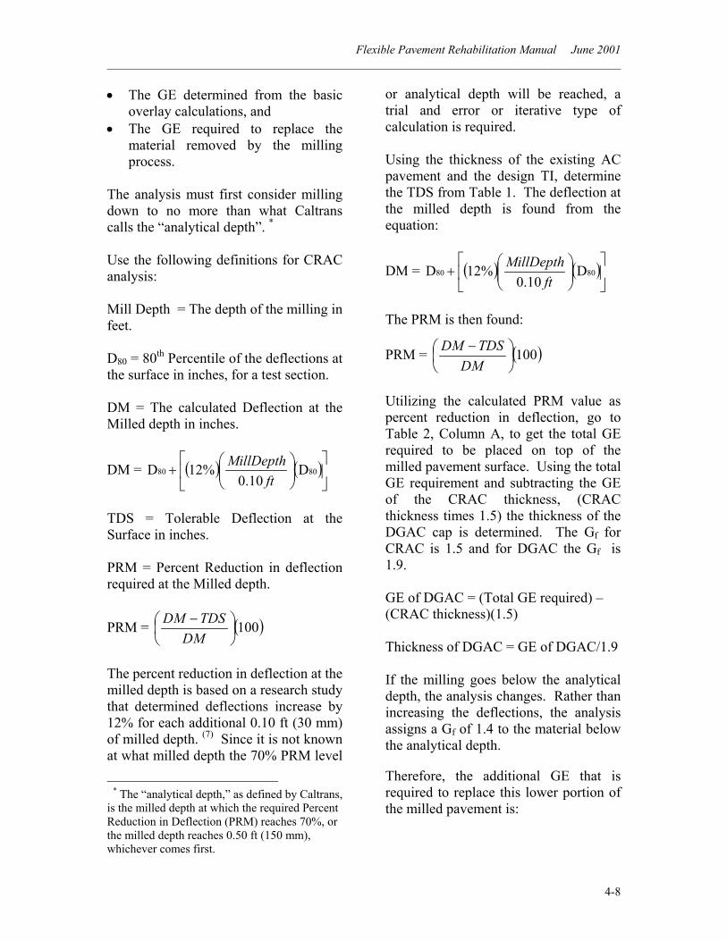
The analysis must first consider milling down to no more than what Caltrans calls the “analytical depth”. * Use the following definitions for CRAC analysis: Mill Depth = The depth of the milling in feet. D80 = 80th Percentile of the deflections at the surface in inches, for a test section. DM = The calculated Deflection at the Milled depth in inches.
DM = ( ) ( )
+ 8080 D
10.0%12D
ftMillDepth
TDS = Tolerable Deflection at the Surface in inches. PRM = Percent Reduction in deflection required at the Milled depth.
PRM = ( )100
−
DMTDSDM
The percent reduction in deflection at the milled depth is based on a research study that determined deflections increase by 12% for each additional 0.10 ft (30 mm) of milled depth. (7) Since it is not known at what milled depth the 70% PRM level
* The “analytical depth,” as defined by Caltrans, is the milled depth at which the required Percent Reduction in Deflection (PRM) reaches 70%, or the milled depth reaches 0.50 ft (150 mm), whichever comes first.
or analytical depth will be reached, a trial and error or iterative type of calculation is required. Using the thickness of the existing AC pavement and the design TI, determine the TDS from Table 1. The deflection at the milled depth is found from the equation:
DM = ( ) ( )
+ 8080 D
10.0%12D
ftMillDepth
The PRM is then found:
PRM = ( )100
−
DMTDSDM
Utilizing the calculated PRM value as percent reduction in deflection, go to Table 2, Column A, to get the total GE required to be placed on top of the milled pavement surface. Using the total GE requirement and subtracting the GE of the CRAC thickness, (CRAC thickness times 1.5) the thickness of the DGAC cap is determined. The Gf for CRAC is 1.5 and for DGAC the Gf is 1.9. GE of DGAC = (Total GE required) – (CRAC thickness)(1.5)
Thickness of DGAC = GE of DGAC/1.9 If the milling goes below the analytical depth, the analysis changes. Rather than increasing the deflections, the analysis assigns a Gf of 1.4 to the material below the analytical depth.
Therefore, the additional GE that is required to replace this lower portion of the milled pavement is:
Flexible Pavement Rehabilitation Manual June 2001 ______________________________________________________________________________________
4-9
Additional GE = [(1.4)(milled depth below the analytical depth)]
This additional GE is added to the total GE determined to be placed on top of the milled pavement surface at the analytical depth.
Finally, a determination is made to see if the designed thicknesses of the CRAC and DGAC are suitable. For CRAC to be considered, it must be cost-effective. Items to consider are:
• The increase in the profile grade should be at least 0.10 ft (30 mm) less than the increase from the basic overlay design; otherwise a basic overlay would be less costly; and
• The amount of CRAC material should be about 10,000 tons (9070 tonnes) or more to be cost effective.
For CRAC design, it is recommended to round up to get the CRAC and DGAC thicknesses.
Example 4-2: Determine the cold-recycled thickness and the DGAC cap thickness for rehabilitation.
Ten-Year TI
80th Percentile Deflection
Existing Structural Section
8.0 0.030 inch 0.55 foot AC 0.50 foot AB 1.00 foot AS
Solution 4-2:
Recommendations to be considered: Structural Adequacy:
A 0.30-ft DGAC overlay. Refer to Example 3-1. (Rubber AC alternatives are discussed in Section 4-20 of this manual.)
Reflective Cracking: A 0.30-ft DGAC overlay. (One-half existing AC thickness.)
Ride Quality: A 0.25-ft DGAC overlay placed in two layers. (Section 3-30).
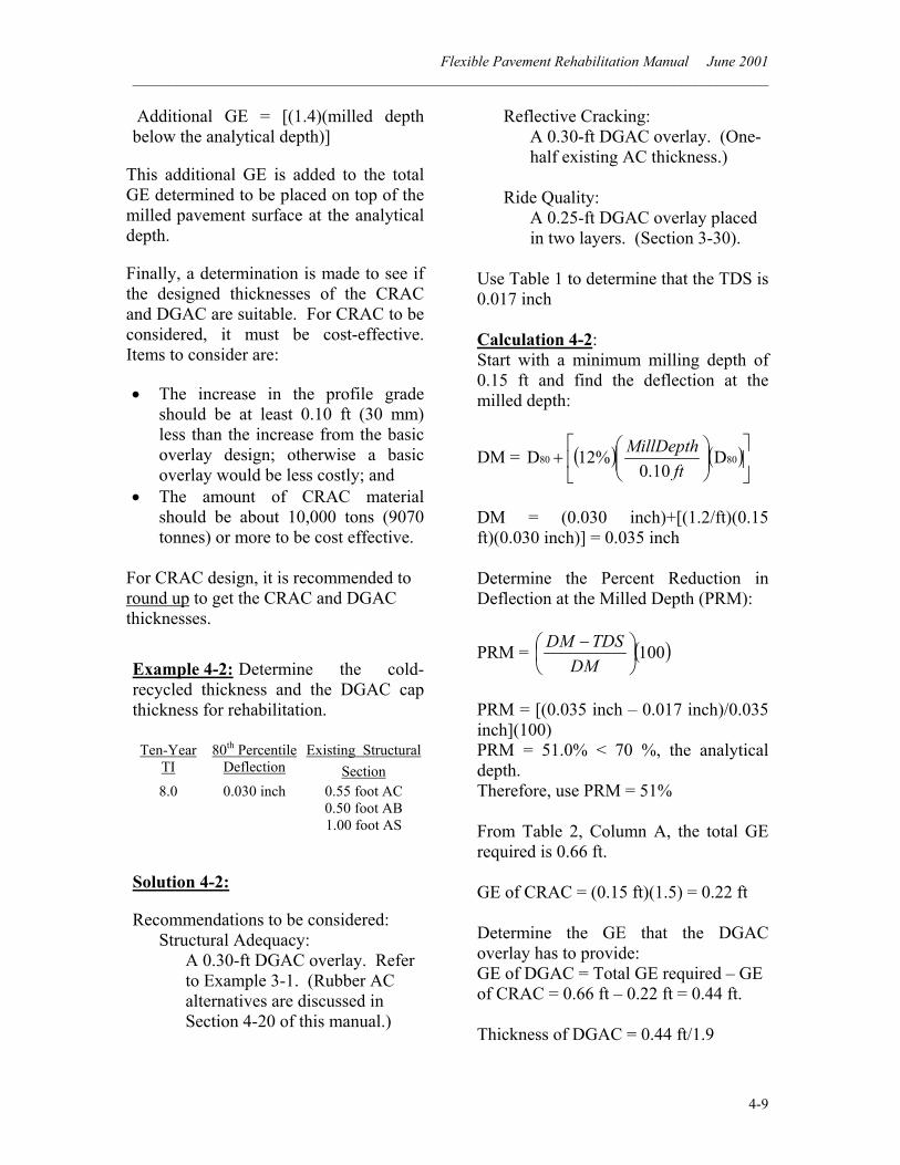
Use Table 1 to determine that the TDS is 0.017 inch Calculation 4-2: Start with a minimum milling depth of 0.15 ft and find the deflection at the milled depth:
DM = ( ) ( )
+ 8080 D
10.0%12D
ftMillDepth
DM = (0.030 inch)+[(1.2/ft)(0.15 ft)(0.030 inch)] = 0.035 inch Determine the Percent Reduction in Deflection at the Milled Depth (PRM):
PRM = ( )100
−
DMTDSDM
PRM = [(0.035 inch – 0.017 inch)/0.035 inch](100) PRM = 51.0% < 70 %, the analytical depth. Therefore, use PRM = 51% From Table 2, Column A, the total GE required is 0.66 ft. GE of CRAC = (0.15 ft)(1.5) = 0.22 ft Determine the GE that the DGAC overlay has to provide: GE of DGAC = Total GE required – GE of CRAC = 0.66 ft – 0.22 ft = 0.44 ft. Thickness of DGAC = 0.44 ft/1.9
Flexible Pavement Rehabilitation Manual June 2001 ______________________________________________________________________________________
4-10
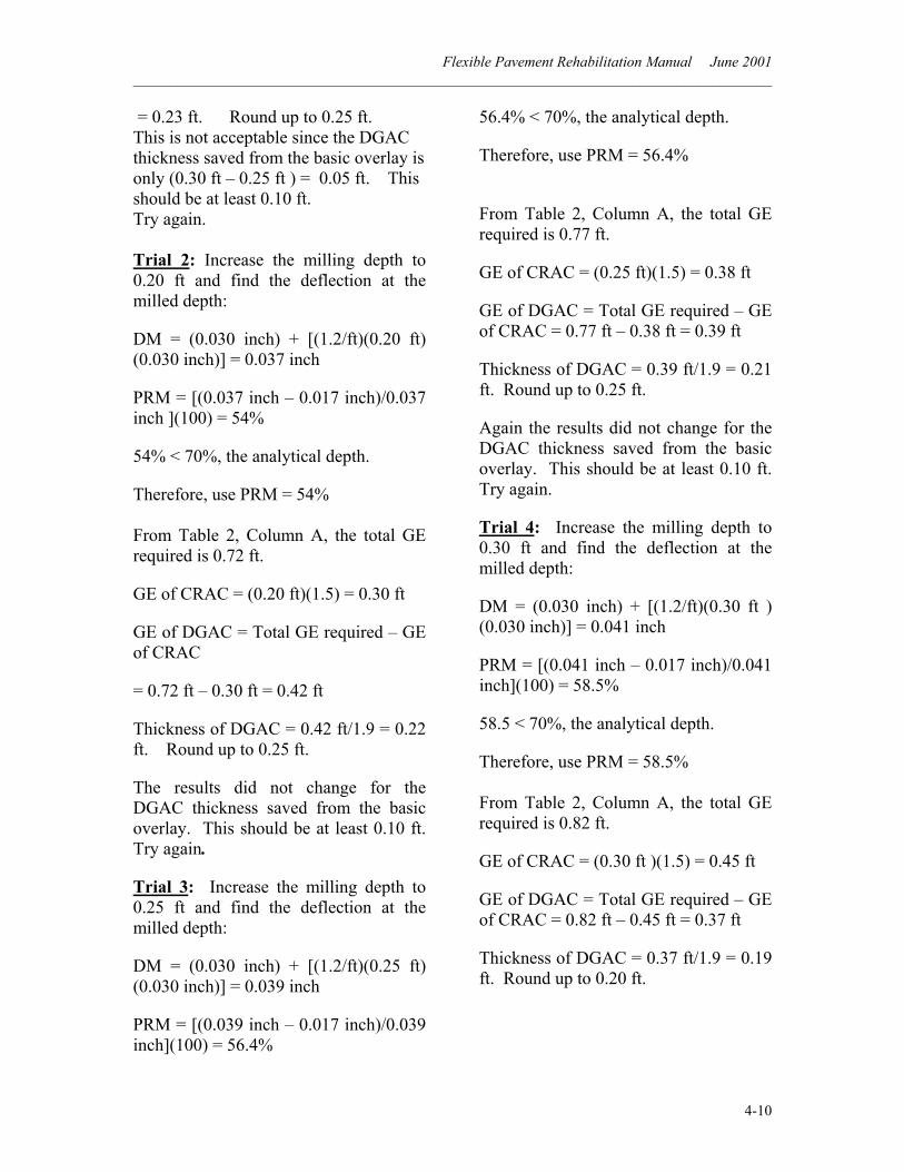
= 0.23 ft. Round up to 0.25 ft. This is not acceptable since the DGAC thickness saved from the basic overlay is only (0.30 ft – 0.25 ft ) = 0.05 ft. This should be at least 0.10 ft. Try again. Trial 2: Increase the milling depth to 0.20 ft and find the deflection at the milled depth:
DM = (0.030 inch) + [(1.2/ft)(0.20 ft) (0.030 inch)] = 0.037 inch
PRM = [(0.037 inch – 0.017 inch)/0.037 inch ](100) = 54%
54% < 70%, the analytical depth.
Therefore, use PRM = 54% From Table 2, Column A, the total GE required is 0.72 ft.
GE of CRAC = (0.20 ft)(1.5) = 0.30 ft
GE of DGAC = Total GE required – GE of CRAC
= 0.72 ft – 0.30 ft = 0.42 ft
Thickness of DGAC = 0.42 ft/1.9 = 0.22 ft. Round up to 0.25 ft.
The results did not change for the DGAC thickness saved from the basic overlay. This should be at least 0.10 ft. Try again.
Trial 3: Increase the milling depth to 0.25 ft and find the deflection at the milled depth:
DM = (0.030 inch) + [(1.2/ft)(0.25 ft) (0.030 inch)] = 0.039 inch
PRM = [(0.039 inch – 0.017 inch)/0.039 inch](100) = 56.4%
56.4% < 70%, the analytical depth.
Therefore, use PRM = 56.4%
From Table 2, Column A, the total GE required is 0.77 ft.
GE of CRAC = (0.25 ft)(1.5) = 0.38 ft
GE of DGAC = Total GE required – GE of CRAC = 0.77 ft – 0.38 ft = 0.39 ft
Thickness of DGAC = 0.39 ft/1.9 = 0.21 ft. Round up to 0.25 ft.
Again the results did not change for the DGAC thickness saved from the basic overlay. This should be at least 0.10 ft. Try again.
Trial 4: Increase the milling depth to 0.30 ft and find the deflection at the milled depth:
DM = (0.030 inch) + [(1.2/ft)(0.30 ft ) (0.030 inch)] = 0.041 inch
PRM = [(0.041 inch – 0.017 inch)/0.041 inch](100) = 58.5%
58.5 < 70%, the analytical depth.
Therefore, use PRM = 58.5% From Table 2, Column A, the total GE required is 0.82 ft.
GE of CRAC = (0.30 ft )(1.5) = 0.45 ft
GE of DGAC = Total GE required – GE of CRAC = 0.82 ft – 0.45 ft = 0.37 ft
Thickness of DGAC = 0.37 ft/1.9 = 0.19 ft. Round up to 0.20 ft.
Flexible Pavement Rehabilitation Manual June 2001 ______________________________________________________________________________________
4-11
Discussion 4-2:
When compared to the basic overlay design, CRAC saves 0.10 ft of virgin DGAC and would also decrease the final profile grade of the shoulder thus saving shoulder-backing material.
Now that the first consideration has been met, consider volume. For a project 10 miles long and pavement 24 feet wide would this produce enough CRAC material to be cost effective? Assuming a compacted AC density of 145 pcf, the milling tonnage is calculated as [(10 miles)(5280 ft/mile) (24 ft)(0.30 ft)(145 lbs/cu ft)]/2000 lbs/ton = 27,562 tons. This is greater than 10,000 tons, the minimum required, and thus is acceptable. By reducing the overlay by 0.10 ft, a saving of 9,187 tons of new material or natural resources would be accomplished. [In this example, milling did not go below the analytical depth – it reached 58.5% compared to the maximum of 70%, and the depth was less than 150 mm (0.50 ft) of milling.] (See Hot Recycled Asphalt Concrete Pavement design for an example of an analysis with milling below the analytical depth.) Cold recycling is, therefore, an acceptable recommendation because it decreases the final overlay profile grade thus saving virgin DGAC and shoulder backing, and it has over 10,000 tons of recycled material making it cost effective for this project to bring in the specialized equipment. Recommendation 4-2: Cold recycle 0.30 ft (90 mm) of the existing pavement and cap with 0.20 ft (60mm) of DGAC.
4 – 50 Hot Recycled Asphalt Concrete Pavement Assembly Bill (AB 1306) encourages State agencies to use more recycled materials in road construction and repairs. Caltrans Deputy Directive DD-17 policy statement, effective November 11, 1993, directs the department to recycle asphalt concrete (AC) whenever feasible. Consideration should be given on every project to recycle AC used in highway construction, maintenance, and rehabilitation projects utilizing the Department’s priority hierarchy (see DD-17). Public and employee health and safety are not to be compromised by recycling AC on any project. At the present time, to be economical on rehabilitation projects, a minimum of 10,000 tons (9070 tonnes) of AC material should be available for the recycle process. In the future, calculations using the then-current price of asphalt material may change the quantity for the minimum tons to be economical for Hot Recycled Asphalt Concrete (HRAC).
Since this design method uses two procedures (milling and replacement), it is one that can be considered appropriate to smooth a rough pavement.
The hot recycling operation consists of the following:
1. Mill the existing AC to obtain the Reclaim Asphalt Pavement (RAP).
2. Haul the RAP to an asphalt mixing plant. *
* This is not hot-in-place recycling (surface recycling) which is a maintenance procedure. Hot-in-place recycling material does not leave the pavement lane site.
Flexible Pavement Rehabilitation Manual June 2001 ______________________________________________________________________________________
4-12
3. Add the RAP and oil or rejuvenating agent to the new DGAC mix to obtain the recycled mix.
4. Haul the HRAC mix back to the project to be spread with a paving machine and then compacted.
5. To prevent damage, traffic should be minimized or not allowed on the milled surface of the lane being recycled depending on the thickness of AC pavement remaining after milling (must be at least 0.25 ft left before allowing any traffic on the lane).
Pavements that are candidates for hot recycling are those with uniform asphalt content. The existence of heavy crack-sealant, numerous patches, open-graded asphalt concrete, and heavy seal coats make the new Hot Recycled Asphalt Concrete (HRAC) mix design inconsistent and therefore more difficult to control the mix properties. To avoid this problem when it occurs and still use this recycle option on projects, a minimum of 0.08 ft (25 mm) should be milled off and stockpiled for other uses (e.g., shoulder backing) prior to the hot recycling operation. Light crack sealing (less than 5 % of the pavement) or a uniform single seal coat will not influence the design sufficiently to require removal.
Caltrans has established a minimum mill depth of 0.10 ft (30 mm) for hot recycling. Since existing pavement thicknesses will have slight variations the hot recycling design should leave at least the bottom 0.15 ft (45 mm) of the existing AC pavement in-place. This is to insure the milling machine does not loosen base material and possibly contaminate the HRAC mix design. Milling down to a depth that leaves only 0.15 ft works only when traffic is not
allowed on the pavement prior too the HRAC material being placed and compacted. The thin remaining surface, if opened to traffic, would cause degradation of the pavement and affect the design life of the new HRAC material.
When designing the HRAC for structural adequacy, the tolerable deflection (TDS) is always determined using the thickness of the existing pavement. In a hot recycling design, the additional GE required to reduce the measured deflection to the tolerable level is a combination of:
• The GE required from the basic overlay calculations, and
• The GE required to replace the material removed by the milling machine.
The percent reduction in deflection at the milled depth is based on a research study that determined that deflections increase 12% for each additional 0.10 ft (30 mm) of milled depth (7).
Since it not known at what milled depth the 70 % PRM level or the “analytical depth*” will be reached, this is a trial and error or iterative type of calculation.
Use the following definitions for HRAC analysis:
Mill Depth = The depth of the milling in feet.
* The analytical depth, as defined by Caltrans, is the depth the required Percent Reduction in Deflection at the milled depth reaches 70%, or the milled depth reaches 0.50 ft (150 mm), whichever comes first. For discussion of deeper milling depths see Remove and Replace.
Flexible Pavement Rehabilitation Manual June 2001 ______________________________________________________________________________________
4-13
D80 = 80th Percentile of the deflections at the surface in inches, for a test section.
DM = The calculated Deflection at the Milled depth in inches.
DM = ( ) ( )
+ 8080 D
10.0%12D
ftMillDepth
TDS = Tolerable Deflection at the Surface in inches.
PRM = Percent Reduction in deflection required at the Milled depth.
PRM = ( )100
−
DMTDSDM
Using the thickness of the existing AC pavement and the design TI, determine the TDS from Table 1. Calculate the deflection at the milled depth from the equation:
DM = ( ) ( )
+ 8080 D
10.0%12D
ftMillDepth
The PRM is then found:
PRM = ( )100
−
DMTDSDM
Utilizing the calculated PRM value go to Table 2, Column A, to get the total GE required to be placed on top of the milled pavement surface. The HRAC thickness is found by dividing the GE by the Gf of 1.9.
If the milling goes below the analytical depth, the analysis changes. The existing material below the analytical depth is considered to be of questionable structural integrity and hence assigned
the Gf of 1.4. The additional GE that is required to replace the portion below analytical depth is calculated by multiplying the Gf of 1.4 by the milled depth below the analytical depth. This is added to the required GE to be placed on top of the milled surface at the analytical depth. The total HRAC thickness required is found by dividing the sum of the two GE’s by the Gf of 1.9.
Finally, a determination is made to see if the designed thickness of the HRAC is suitable. For HRAC to be considered, it must be cost effective. Items to consider are:
• The increase in the profile grade should be at least 0.10 ft (30 mm) less than the increase from the basic overlay design; otherwise a basic overlay would be less costly; and
• The amount of RAP should be about 10,000 tons (9070 tonnes) or more to be cost effective.
Unlike cold recycled material, HRAC pavement can be used as a surface course without a DGAC cap. The Gf of HRAC is the same as DGAC (i.e., Gf = 1.9 ). Therefore, this analysis can also be used for DGAC on milled pavement and the reclaimed asphalt pavement could be stockpiled for future use.
Example 4-3: Determine the milling depth and the hot-recycled thickness for rehabilitation.
Ten-Year TI
80th Percentile Deflection
Existing Structural Section
11.0 0.031 inch 0.75 foot AC 0.50 foot AB 1.00 foot AS
Flexible Pavement Rehabilitation Manual June 2001 ______________________________________________________________________________________
4-14
Solution 4-3:
Recommendations to be considered: Structural Adequacy:
A 0.50-ft DGAC overlay. Refer to Example 3-1. (Rubber AC alternatives are discussed in Section 4-20 of this manual.)
Reflective Cracking: A 0.35-ft DGAC overlay. (One-half existing AC thickness with a maximum of 0.35 ft.)
Ride Quality: A 0.25-ft DGAC overlay placed in two layers. (Section 3-30).
Use Table 1 to determine that the TDS is 0.011 inch.
Calculation 4-3: Start with a milling depth of 0.15 ft and find the deflection at the milled depth
DM = ( ) ( )
+ 8080 D
10.0%12D
ftMillDepth
DM = (0.031 inch) + [(1.2/ft)(0.15 ft)(0.031 inch)] = 0.037 inch
Determine the Percent Reduction in Deflection at the Milled Depth (PRM):
PRM = ( )100
−
DMTDSDM
PRM = [(0.037 inch – 0.011 inch)/0.037 inch](100)
PRM = 69.9% ≈ 70%, the analytical depth.
Therefore, use PRM = 69.9%
From Table 2, Column A, the total GE required is 1.06 ft.
Find the HRAC thickness: GE/Gf = 1.06 ft/1.9 = 0.56 ft. Round to 0.55 ft.
The increase in grade is (0.55 ft – 0.15 ft) = 0.40 ft. This is acceptable since the reduction in profile grade from the basic overlay is 0.10 ft. This would save 0.10 ft of virgin DGAC and would also decrease the final grade of the shoulder thus saving shoulder-backing material.
The quantity for milling 0.15 ft in two lanes per mile is calculated as follows:
[(1 mile)(5280 ft/mile)(24 ft)(0.15 ft)(145 lbs/cu ft)]/2000 lbs/ton = 1,378 tons. The project should be long enough (and/or wide enough) to provide at least 10,000 tons for recycling. 10,000 tons/1,378 tons per mile = 7.3 miles.
The percentage RAP in the mix is (0.15 ft milled/0.55 ft HRAC thickness)(100) = 27%. In order to get more RAP and use less virgin material, the milling depth should be increased.
Since the analytical depth was nearly reached (69.9%) at the milled depth of 0.15 ft, all milled and removed material below that level will be considered to be material with a Gf of 1.4.
Trial 2: Increase the milled depth to 0.25 ft (0.10 ft below the analytical depth) to save more material. Total thickness of the HRAC = [(GE required at 0.15 ft milled depth) + (GE required due to additional milling)]/1.9.
HRAC = [(1.06 ft) + (0.10 ft)(1.4)]/1.9 = 0.63 ft of HRAC. Round to 0.65 ft.
Flexible Pavement Rehabilitation Manual June 2001 ______________________________________________________________________________________
4-15
The percent of RAP is (0.25 ft/0.65 ft)(100) = 38 %.
Trial 3: Increase the milled depth to 0.30 ft (0.15 ft below the analytical depth) to save more material.
HRAC = [(1.06 ft) + (0.15 ft)(1.4)]/1.9 = 0.67 ft. Round to 0.65 ft.
The percent of RAP is (0.30 ft/0.65 ft)(100) = 46 %.
Discussion 4-3: At this milling depth the RAP content is 46% and the increase in grade is 0.35 ft. This will save 0.15 ft of new material compared with the 0.50 ft DGAC overlay needed by the basic overlay and would also decrease the final grade of the shoulder thus saving shoulder-backing material. Recommendation 4-3: Mill 0.30 ft (90 mm) of the existing pavement and then replace it with a total thickness of 0.65 ft (195 mm) of HRAC. 4 – 60 Remove and Replace When it is not possible to maintain the existing profile grade using the hot recycled hot mix (HRAC) design, the remove-and-replace strategy can be used. The Remove-and-Replace (R&R), sometimes called Mill and Fill, operation consists of milling the entire AC pavement and possibly into the base material. (When using several milling passes, part of the AC may be used to reclaim asphalt pavement for HRAC.) The entire milled depth is then replaced with DGAC or HRAC.
This design method may be less reliable the deeper the milling is performed. A
study has shown that deflections will increase an average of 12% for each 0.10-ft of pavement milled off (based on milling depths down to about 0.50 ft).(7) The greater the depth of milling the less accurate the determination may be of the calculated deflections.
R&R design from deflections is also less reliable if a bulldozer or a scraper is used to remove the material under the pavement instead of a milling machine. This method of removing material disturbs the integrity of the in-place material from which the deflections were measured.
The alternative to the use of this design is the R-value design method (see HDM Chapter 600).
When using the R&R method in designing for structural adequacy, the tolerable deflection (TDS) is always determined using the thickness of the existing pavement.
The analysis used for R&R is similar to the HRAC analysis (Section 4-50). First consider milling down to what is called the analytical depth. This is the depth where the required Percent Reduction in Deflection at the Milled depth (PRM) reaches 70% or to 0.50 ft (150 mm), or to the bottom of the pavement, whichever comes first. As discussed above, the 70% PRM is based on an increase in deflection of 12% for each 0.10-ft (30 mm) of milled pavement. This is an iterative type of calculation since it not known at what milling depth the 70% level will be reached. Use the following definitions for the R&R analysis:
Mill Depth = The depth of milling in feet.
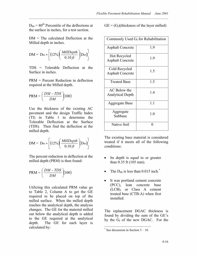
Flexible Pavement Rehabilitation Manual June 2001 ______________________________________________________________________________________
4-16
D80 = 80th Percentile of the deflections at the surface in inches, for a test section.
DM = The calculated Deflection at the Milled depth in inches.
DM = ( ) ( )
+ 8080 D
10.0%12D
ftMillDepth
TDS = Tolerable Deflection at the Surface in inches.
PRM = Percent Reduction in deflection required at the Milled depth.
PRM = ( )100
−
DMTDSDM
Use the thickness of the existing AC pavement and the design Traffic Index (TI) in Table 1 to determine the Tolerable Deflection at the Surface (TDS). Then find the deflection at the milled depth.
DM = ( ) ( )
+ 8080 D
10.0%12D
ftMillDepth
The percent reduction in deflection at the milled depth (PRM) is then found:
PRM = ( )100
−
DMTDSDM
Utilizing this calculated PRM value go to Table 2, Column A to get the GE required to be placed on top of the milled surface. When the milled depth reaches the analytical depth, the analysis changes. The GE for the material milled out below the analytical depth is added to the GE required at the analytical depth. The GE for each layer is calculated by:
GE = (Gf)(thickness of the layer milled)
Commonly Used Gf for Rehabilitation
Asphalt Concrete 1.9
Hot Recycled Asphalt Concrete 1.9
Cold Recycled Asphalt Concrete 1.5
Treated Base 1.5
AC Below the Analytical Depth 1.4
Aggregate Base 1.1
Aggregate Subbase 1.0
Native Soil 0
The existing base material is considered treated if it meets all of the following conditions:
• Its depth is equal to or greater than 0.35 ft (105 mm).
• The D80 is less than 0.015 inch.* • It was portland cement concrete
(PCC), lean concrete base (LCB), or Class A cement treated base (CTB-A) when first installed.
The replacement DGAC thickness is found by dividing the sum of the GE’s by the Gf of the new DGAC. For the * See discussion in Section 3 – 10.
Flexible Pavement Rehabilitation Manual June 2001 ______________________________________________________________________________________
4-17
R&R design method, use the Gf for the new DGAC commensurate with the TI and AC thickness found in Table 608.4 of the Highway Design Manual (HDM).*(8) The total DGAC thickness can be solved for each 0.05 ft (15 mm) of material milled until the desired profile is reached. Round the replacement thickness to the nearest 0.05 ft.
Example 4-4: Determine the milling depth and the DGAC thickness for rehabilitation to maintain the existing profile grade.
Ten-Year TI
80th Percentile Deflection
Existing Structural Section
12.0 0.030 inch 0.75 foot AC 0.50 foot AB 0.83 foot AS
Solution 4-4:
Recommendations to be considered: Structural Adequacy:
Solve for a basic DGAC overlay. Use Table 1 to find that the TDS is 0.009 inches.
PRD = [(0.030 inches – 0.009 inches)/0.030 inches](100) = 70.0 %
Use Table 2, Column A, to determine that 1.06 ft is the increase in GE required to reduce the D80 to the tolerable deflection level.
* For an AC thickness greater than 0.50 ft (150 mm), the Gf increases as the thickness increases; see HDM Index 608.4 (8).
DGAC overlay thickness = (1.06 ft)/(1.9) = 0.56 ft. Round to 0.55 ft.
Reflective Cracking:
A 0.35-ft DGAC overlay. (One-half existing AC thickness with a maximum of 0.35 ft.)
Ride Quality:
A 0.25-ft DGAC overlay placed in two layers. (Section 3-30).
Calculation 4-4: Now provide a rehabilitation strategy by the R&R method that maintains the existing profile grade.
In this example, the analytical depth of 70% was reached at the surface, so to obtain the GE below the surface, all the calculations will be multiplying the Gf times the thickness of the layer milled. These values will then be added to the GE required at the surface.
Find the GE removed when milling from the analytical depth (the surface in this example) down to the bottom of the pavement: GE = (0.75 ft)(1.4) = 1.05 ft.
This is added to the GE at the surface and divided by the Gf of the new DGAC to get the thickness required: (1.06 ft) + (1.05 ft) = 2.11 ft GE.
This is a trial and error problem since the Gf that matches the new DGAC thickness is unknown at this time. Assume a Gf of 1.9. (This is usually a good starting point since it is about the middle of Table 608.4).
GE/Gf = (2.11 ft)/1.9 = 1.11 ft of DGAC. Round to 1.10 ft.
From Table 608.4 of the HDM, the Gf = 2.09 for a thickness of 1.10 ft.
Flexible Pavement Rehabilitation Manual June 2001 ______________________________________________________________________________________
4-18
Calculate the replacement thickness using the Gf of 2.09 for the 1.10-ft. The DGAC thickness is:
GE/Gf = (2.11 ft)/(2.09) = 1.01 ft. Round to 1.00 ft of DGAC.
To match the thickness for which the Gf is used, the answer appears to be between 1.00 ft and 1.10 ft. Assuming a thickness of 1.05, the Gf is equal to 2.05 (HDM, Table 608.4) and thus the DGAC thickness needed is:
GE/Gf = (2.11 ft)/(2.05) = 1.03 ft.
Round to 1.05 ft of DGAC. (This matches the thickness for which the Gf was used.)
When the milling extends to the bottom of the pavement (0.75 ft ), the removed material is replaced with 1.05 ft of DGAC for an increase in the profile grade of 0.30 ft. This is 0.25 ft lower in profile grade than the basic overlay design method provided. This would be an acceptable solution except the problem was to match the existing grade.
Therefore, find to what depth the milling has to go to have no increase in profile grade. Below the pavement the Gf for the existing 0.50 ft of AB material is 1.1. The additional GE to be replaced is 1.1 times the thickness of the AB layer milled. This will be added to the GE at the analytical depth (at the surface in this example) and the GE at the bottom of the pavement; then the total is divided by the Gf of the new DGAC.
Instead of trying each 0.05-ft of milling, estimate to what depth the milling might have to go. A quick calculation of the Gf ratio times the increase in grade, when milling stopped at the bottom of the
pavement, is one way that sometimes works to estimate the needed additional depth below the pavement.
[(1.9)/(1.1)](0.30 ft) = 0.52 ft. Round to 0.50 ft.
This would be a total depth of 1.25 ft (0.75 ft + 0.50 ft).
Find the GE value of the AB removed to the estimated depth (0.50 ft):
GE = (0.50 ft)(1.1) = 0.55 ft.
This is added to the GE’s at the analytical depth and bottom of the pavement, and then divided by the Gf of the DGAC to yield the required thickness:
GE = (1.06 ft) + (1.05 ft) + (0.55 ft) = 2.66 ft.
For the estimated 1.25 ft depth, the Gf is 2.18 (HDM, Table 608.4).
GE/Gf = (2.66 ft)/2.18 = 1.22 ft of DGAC. Round to 1.20 ft.
This is less than the 1.25-ft thickness that was estimated; the depth of the AB to be removed was too much. Therefore, reduce the estimate for the milled depth of the AB below the pavement. Try 0.45 ft into the AB, for a total thickness of 1.20 ft (0.75-ft pavement and 0.45 ft base).
GE = (0.45 ft)(1.1) = 0.50 ft. This is added to the GE’s at the analytical depth and bottom of the pavement, then divided by the Gf of the 1.20 ft of DGAC obtained from Table 608.4 of the HDM (Gf = 2.15 ):
GE/Gf = (1.06 ft + 1.05 ft + 0.50 ft)/2.15 = 1.21 ft
Flexible Pavement Rehabilitation Manual June 2001 ______________________________________________________________________________________
4-19
Round to 1.20 ft. (This matches the thickness for which the Gf was used).
Discussion 4-4: Since this is quite deep for the milling analysis the R&R method may not be reliable*, check the R-value design to see if it is close to the 1.20-ft thickness. Only 0.05 ft of AB remains above the aggregate subbase (AS), therefore use the R-value of the AS with the TI10 of 12. (The R-value is 50 for Class 1 and 2, and 40 for Class 3 as per HDM, Table 608.4). Assume an R-value of 50. The equation to determine the GE using the R-value is as follows:
GE required=(0.0032)(TI)(100–R-value)
GE = (0.0032)(12)(100-50) = 1.92
For a full depth design, add a safety factor to the GE of 0.10 ft to allow for construction tolerances as per the HDM. The GE required is then 2.02 ft.
Since we expect to be close to the same depth determined by the deflection method (a good place to start), use a Gf of 2.15 for the determined 1.20-ft of AC. (Table 608.4 of the HDM).
GE/Gf = (2.02 ft)/(2.15) = 0.94 ft. Round to 0.95 ft.
This is less than the estimated depth of 1.2 ft. The Gf needs to be lower to increase the depth and balance the equation. Try a Gf of 2.02 for a 1.00-ft thickness.
* The analysis is based on deflections measured on material in the structural layers as well as several feet of original ground or fill. The deeper these layers are disturbed or removed the more the analysis is based on material that no longer exists and the analysis becomes less reliable. Engineering judgment needs to be applied.
GE/Gf = (2.02 ft)/(2.02) = 1.00 ft.
The R-value design method determined that the existing structural section should be removed to a depth of 1.00 ft and replaced with new DGAC. The Remove and Replace design method produced a thickness of 1.20 ft of new material. Engineering judgment is needed as to which depth to use. In this case the deflection measurements gives the more conservative answer and the engineer working on the project may have other data to support the use of the R&R method.
Recommendation 4-4: Mill 0.75 ft (225 mm) of the existing pavement and 0.45 ft (135 mm) of the AB material. Then replace those layers with 1.20 ft (360 mm) of DGAC. This will maintain the profile grade. 4 – 70 Asphalt Concrete Overlay Placed on a Cushion Course In this option, an aggregate base (AB) layer (cushion course) is placed prior to placing the DGAC pavement. It is used
• to raise the profile grade above a flooded area; or
• when sections of newly constructed added-on lanes, etc., produce grade changes for existing roadways; or
• when the basic overlay design produces a larger than desired dense graded asphalt concrete (DGAC) overlay thickness (too costly). As this design method uses two procedures it can also be used to smooth a rough pavement.
Flexible Pavement Rehabilitation Manual June 2001 ______________________________________________________________________________________
4-20
As a review, the basic overlay design method is based on reducing the 80th
percentile deflection (D80) at the surface back to a tolerable level (TDS). Knowing the TI, 80th percentile deflection, and the existing AC pavement thickness, the gravel equivalence (GE) can be determined. Using a gravel factor ( Gf ) of 1.9, the thickness of the new AC overlay can be calculated. Please note that when determining the mean and standard deviation of a test section, do not omit the individual measurements on isolated failed areas, since patching failed areas will not be recommended when designing an asphalt concrete overlay placed on a cushion course. For this option, the design is based on the same principle as the basic overlay with two exceptions: • the GE required, much like new
construction, is obtained with combinations of AB and AC pavement to reduce the D80 for the new AC pavement, and
• the Gf varies with the TI and thickness, again like new construction.*
The DGAC gravel factor (Gf ) commensurate with the TI and new AC thickness found in Table 608.4 of the HDM is used. However, no safety factor of additional thickness for new construction as described in the HDM for the R-value design is to be applied. As in new construction of highway pavement, an AB layer should never be * For an AC thickness greater than 0.50 ft (150 mm), the Gf increases as the thickness increases; see HDM Index 608.4 (8).
placed less than 0.35 ft (105 mm) thick and the DGAC surface should never be placed less than 0.20 ft (60 mm) thick on the AB. Example 4-5: Determine the AC and AB thicknesses for a Cushion Course design.
Ten-Year TI
80th Percentile Deflection
Existing Structural Section
8.0 0.056 inch 0.55 foot AC 0.50 foot AB 0.83 foot AS
Solution 4-5:
Recommendations to be considered: Reflective cracking and ride quality are inherently provided for in this type of design. Structural Adequacy: Since this design is much like new construction design, the thickness of the existing AC pavement does not enter into the calculations for the aggregate base and new AC thicknesses. To find the minimum DGAC thickness required over the AB, use the standard design equation from the HDM: GE = (0.0032)(TI)(100-R) Gf for AB is 1.1. The R-value for AB is 78. The GE required over the AB is: GE = (0.0032)(8)(100-78) = 0.56 ft. AC = GE/Gf. Use the Gf obtained from Table 608.4 of the HDM (Estimate what the thickness will be and use that Gf ; or as in this example, start with a Gf of
Flexible Pavement Rehabilitation Manual June 2001 ______________________________________________________________________________________
4-21
2.01; this Gf is good for all values of AC thickness up to 0.50 ft and a TI of 8.0). Therefore, this is an iterative calculation process to get the solution. Round the thickness to the nearest 0.05 ft. AC = GE/Gf = 0.56 ft/2.01 = 0.28 ft. Round to 0.30 ft.
Actual GE provided by the DGAC = (0.30 ft)(2.01) = 0.60 ft.
Using Table 1, the TDS of the new DGAC thickness (0.30-ft) with a TI of 8.0 is 0.022 inch. Calculate the percent reduction in deflection required at the surface (PRD) of the existing pavement (D80 = 0.056 inch) to reduce the TDS for the new pavement to 0.022 inch.
PRD = ( )10080
80
AverageDTDSAverageD −
PRD = [(0.056 inch – 0.022 inch)/0.056 inch](100) = 60.7%. The next step is to obtain the GE required (combination of AB and AC) to reduce the deflection measured on the existing surface (0.056 inch) to the tolerable deflection level of the new AC thickness (0.022 inch).
Using Table 2, Column B, determine the total increase in GE required to reduce D80 to the TDS for the new pavement using a PRD of 60.7%. GE (Total required)= 1.10 ft.
Subtract the GE of the actual DGAC thickness from the total GE required to obtain the GE of the AB:
GE of AB = 1.10 ft – 0.60 ft = 0.50 ft.
Finally, divide by the Gf of the AB and round to the nearest 0.05 ft:
AB = GE/Gf = 0.50 ft/1.1 = 0.45 ft. Use 0.45 ft of AB.
Recommendation 4-5: Use 0.30 ft (90 mm) of DGAC over 0.45 ft (135 mm) of AB Example 4-6: What would be the AB thickness if the DGAC thickness for the previous example were increased to 0.55 ft? The Gf varies for AC thicknesses greater than 0.50 ft. From HDM Table 608.4, for a TI of 8.0 and 0.55 ft of AC, the GE is 1.12 ft. Tolerable deflection level of the new pavement from Table 1, is 0.017 inch, therefore PRD = [(0.056 inch – 0.017 inch)/0.056
inch ] (100) = 69.6 %.
Using Table 2, Column B, determine the total increase in GE required to reduce D80 to the TDS for the new pavement: GE = 1.41 ft.
Subtract the GE of the actual DGAC thickness (1.12 ft ) from the total GE required to get the GE of the AB:
GE of AB = 1.41 ft – 1.12 ft = 0.29 ft.
Flexible Pavement Rehabilitation Manual June 2001 ______________________________________________________________________________________
4-22
Finally, divide the GE of AB by its Gf and round to the nearest 0.05-ft to calculate the AB thickness required:
GE/Gf = 0.29 ft/1.1 = 0.26 ft. Round to 0.25 ft.
Use the minimum thickness, 0.35 ft for AB.
Recommendation 4-6: Use 0.55 ft (165 mm) of DGAC over 0.35 ft ( 105 mm) of AB 4 – 80 Cushion Course Design with Drainage Layer In this option, an AB layer (cushion course) is placed prior to placing a drainage layer and DGAC pavement. It is similar in design to an “Asphalt Concrete Overlay Placed on a Cushion Course” described in Section 4-70. The Gravel Equivalence (GE) for the added layer of the Asphalt Treated Permeable Base (ATPB) is subtracted from the total GE required. [Note that a drainage layer requires positive outflow and is discussed in Highway Design Manual (HDM), Chapter 600, Topic 606]. The thickness of the ATPB is 0.25 ft (75mm) unless a unique combination of conditions exists. See HDM, Section 606.2.
The Gf for ATPB is 1.4 as obtained from the HDM, Table 608.4. The GE that the 0.25-ft (75-m) ATPB layer contributes to the total required thickness is: GE = (Gf )(AB thickness) = (1.4)(0.25 ft) GE = 0.35 ft. Since an ATPB drainage layer has an indeterminate R-value, the minimum
thickness of the DGAC over the ATPB is based on the equation below. The GE of the AC is 0.4 of the total GE required over a 50 R-value material [see HDM 608.4 (4) (b)]. The minimum thickness of DGAC cover over the ATPB should never be less than 0.20 ft (60 mm).
GE over ATPB = [(0.4)(GE required over a 50 R-value material)] GE = [(0.4)(0.0032)(TI)(100-R)]
Example 4-7: Use the same data from the example problem solved in the “Asphalt Concrete Overlay Placed on A Cushion Course” design, Section 4-70. Determine the AC, ATPB and AB thicknesses for a Cushion Course design with drainage layer.
Ten-Year TI
80th Percentile Deflection
Existing Structural Section
8.0 0.056 inch 0.55 foot AC 0.50 foot AB 0.83 foot AS
Solution 4-7:
Recommendations to be considered: Reflective cracking and ride quality are inherently provided for in this type of design. Structural Adequacy: Find the minimum DGAC thickness over the ATPB:
The GE over the ATPB is [(0.4)(0.0032)(8)(100-50)] = 0.51 ft.
Flexible Pavement Rehabilitation Manual June 2001 ______________________________________________________________________________________
4-23
From the HDM, Table 608.4, the Gf for any thickness of DGAC 0.50 ft or less is 2.01. The minimum thickness of cover for the ATPB is: GE/Gf = (0.51 ft)/(2.01) = 0.25 ft. Use 0.25 ft. Calculate the actual GE provided by the 0.25-ft of DGAC: GE = (2.01)(0.25 ft) = 0.50 ft. Use the thickness of the new AC pavement and the design Traffic Index (TI) in Table 1 to determine that the Tolerable Deflection at the Surface (TDS) is 0.024 inch. Calculate the percent reduction in deflection required at the surface (PRD) of the existing pavement (D80 = 0.056 inch), to reduce the TDS for the new pavement to 0.024 inch:
PRD = ( )10080
80
AverageDTDSAverageD −
PRD = [(0.056 inch – 0.024 inch)/0.056 inch]100 = 57.1 %
Utilizing the calculated PRD value, go to Table 2, Column B to determine the increase in GE required to reduce the D80 to the TDS for the new pavement:
GE (Total Required) = 0.98 ft.
Subtract the GE of the actual DGAC thickness (0.50 ft) and the GE of the ATPB (0.35 ft) from the total GE required to get the GE of the AB.
GE (Total Required) = (GE of DGAC) + (GE of ATPB) + (GE of AB)
GE of AB = (0.98 ft)–(0.50 ft) – (0.35 ft) GE = 0.13 ft.
AB Thickness = GE/Gf = 0.13 ft/1.1
AB = 0.11 ft. Round to 0.10 ft.
Use the minimum thickness, 0.35 ft for AB.
Recommendation 4-7 Use 0.25 ft (75 mm ) of DGAC, over 0.25 ft (75 mm ) of ATPB, over 0.35 ft (105 mm ) of AB. 4 – 90 Asphalt Concrete Overlay with Drainage Layer Determination and discussion of the need for a drainage layer can be found in the California Highway Design Manual (HDM), in Chapter 600, Topic 606. Placement and design considerations such as a positive outflow requirement for a drainage layer are also found in the HDM. This strategy can also be used to smooth rough pavement as well as provide the needed drainage since it utilizes multiple layers. The AC overlay thickness portion of this strategy is determined using the design method for a basic overlay, with the Gravel Equivalence (GE) of the Asphalt Treated Permeable Base (ATPB) layer subtracted from the total GE required. The thickness of the ATPB is 0.25 ft (75 mm) unless unique combinations of conditions were to exist. [See Highway Design Manual (HDM), Chapter 600, Topic 606]. The standard layer of 0.25 ft (75 mm) will generally provide greater drainage capacity than is needed under AC pavements. Therefore, the standard thickness generally provides sufficient drainage and provides an allowance to compensate for construction tolerances.
Flexible Pavement Rehabilitation Manual June 2001 ______________________________________________________________________________________
4-24
Calculate the GE that the ATPB (Gf is 1.4) contributes to the total required thickness: GE = (1.4)(0.25 ft) = 0.35 ft. Since an ATPB drainage layer has an indeterminate R-value, the minimum thickness of the DGAC over the ATPB is based on the equation below. The GE of the AC is 0.4 of the total GE required over a 50 R-value material [HDM 608.4 (4) (b)]. The minimum thickness of DGAC over the ATPB should never be less than 0.20 ft (60 mm). GE over ATPB = [(0.4)(GE required over a 50 R-value material)]. GE = [(0.4)(0.0032)(TI)(100-R)]
Example 4-8: Determine the AC and ATPB thicknesses for an existing AC pavement.
Ten-Year TI
80th Percentile Deflection
Existing Structural Section
10.0 0.030 inch 0.55 foot AC 0.50 foot AB 1.00 foot AS
Calculations 4-8:
Check for overlay thickness required for structural adequacy. Step 1:
Obtain tolerable deflection at the surface (TDS). Use Table 1: AC = 0.55 ft and TI = 10.0 TDS = 0.012 inch
Step 2: Compare average D80 to TDS. 0.030 > 0.012
Stem 3: Calculate Percent Reduction in Deflection required.
( ) %60100030.0
012.0030.0=
−
Step 4:
Determine Gravel Equivalence (GE) required for deflection reduction. Use Table 2; Column A GE = 0.85 ft
Step 5: Find the minimum DGAC thickness over the ATPB:
GE over ATPB drainage layer is = (0.4)(0.0032)(10)(100 – 50) = 0.64 ft. The DGAC thickness using a Gf = 1.9 is: AC = GE/Gf = 0.64 ft/1.9 = 0.34 ft. Round to 0.35 ft. Step 6:
Find the DGAC thickness required to reduce the 80th percentile deflection down to the tolerable level. (Use the standard ATPB layer thickness of 0.25 ft.) The GE that the 0.25-ft ATPB layer provides is: GE = (ATPB thickness)(Gf ) GE = (0.25)(1.4) = 0.35 ft GE of DGAC = Total GE required - GE of ATPB GE = 0.85 ft – 0.35 ft = 0.50 ft
Flexible Pavement Rehabilitation Manual June 2001 ______________________________________________________________________________________
4-25
Thickness of DGAC = GE/Gf DGAC = 0.50 ft/1.9 = 0.26 ft. Round to 0.25 ft. This is less than the minimum DGAC thickness over the ATPB layer.
Use 0.35 ft DGAC over 0.25 ft ATPB for structural adequacy. Check overlay thickness required for reflective crack retardation. To retard reflective cracks entering the new overlay from the pavement below choose a thickness for the new overlay at least one-half the thickness of the existing AC pavement being overlaid (up to a maximum of 0.35 ft (105 mm) for an underlying aggregate base). Determine half of the existing pavement thickness:
overlay = 255.0 = 0.275 Round
to 0.30 ft. Check overlay thickness required for smoothness. The ride quality is improved by adding a minimum 0.25-ft DGAC overlay placed in two layers. Discussion 4-8: • Reflective cracking requirement is
less than the 0.35-ft DGAC thickness plus the 0.25-ft layer of ATPB.
• The ride quality is going to be improved due to the two layers being placed.
Therefore, structural adequacy governs the overlay design thickness. Recommendation 4-8: Place 0.35 ft (105 mm ) of DGAC over 0.25 ft (75 mm) of ATPB.
Flexible Pavement Rehabilitation Manual June 2001 ______________________________________________________________________________________
5-1
CHAPTER 5
APPENDIX
5 – 10 Guidelines for Involving Moisture and Temperature in Flexible Pavement Rehabilitation Moisture and temperature affect the strength of the structural section and is reflected in the measured deflections. Pavement deflections increase with an increase in the amount of moisture in the underlying materials and an increase in the temperature of the pavement at the time of testing. A saturated structural section and subgrade along with a hot summer day would be the extreme condition; the structural section would be in its weakest condition and produce the highest deflection. Fortunately, this environment is not the norm in California. The hot season is normally the dry time of the year. The most favorable time to measure deflections (designing for the worst case) is in the spring of the year; the moisture content of the basement soils will be at or near their highest values and will affect the deflections more than the moderate temperature. Presently, the magnitude of highways needing rehabilitation makes deflection measurements a year-round endeavor. Judgment is required when considering the seasonal variation of temperature, moisture content, and test date for areas throughout the state. With the large variation of elevation in California, “spring” comes at different times of the year. Fortunately, this allows a large
window of time to schedule deflections throughout the state. Deflections measured in the late summer or early fall in the valley and desert areas, may be influenced primarily by the temperature and little by moisture content. At the present time, Caltrans provides no correction factor for temperature or moisture content. Since higher pavement temperatures produce higher deflections, using the actual measured deflection when the average pavement temperature is 70º F (21º C) or more will somewhat compensate for the lower moisture content. Deflections should not be measured when the pavement surface temperature is 45º F (7º C) or lower. The pavement temperature above which deflection measurements should not be made (the maximum pavement temperature at the time of testing) will vary depending on the weight of the deflection apparatus being used. The California Deflectometer with the Benkelman Beam, and Falling Weight Deflectometer, due to their higher weight, should not be used to measure deflections when the pavement surface temperature is 130º F (54º C) or higher. The lighter weight of the Dynaflect can be used at any pavement temperature above 45o F (7o C). If other engineers or agencies elect to use this Caltrans manual, the decision and the method to correct for moisture content and/or temperature is left to their discretion.
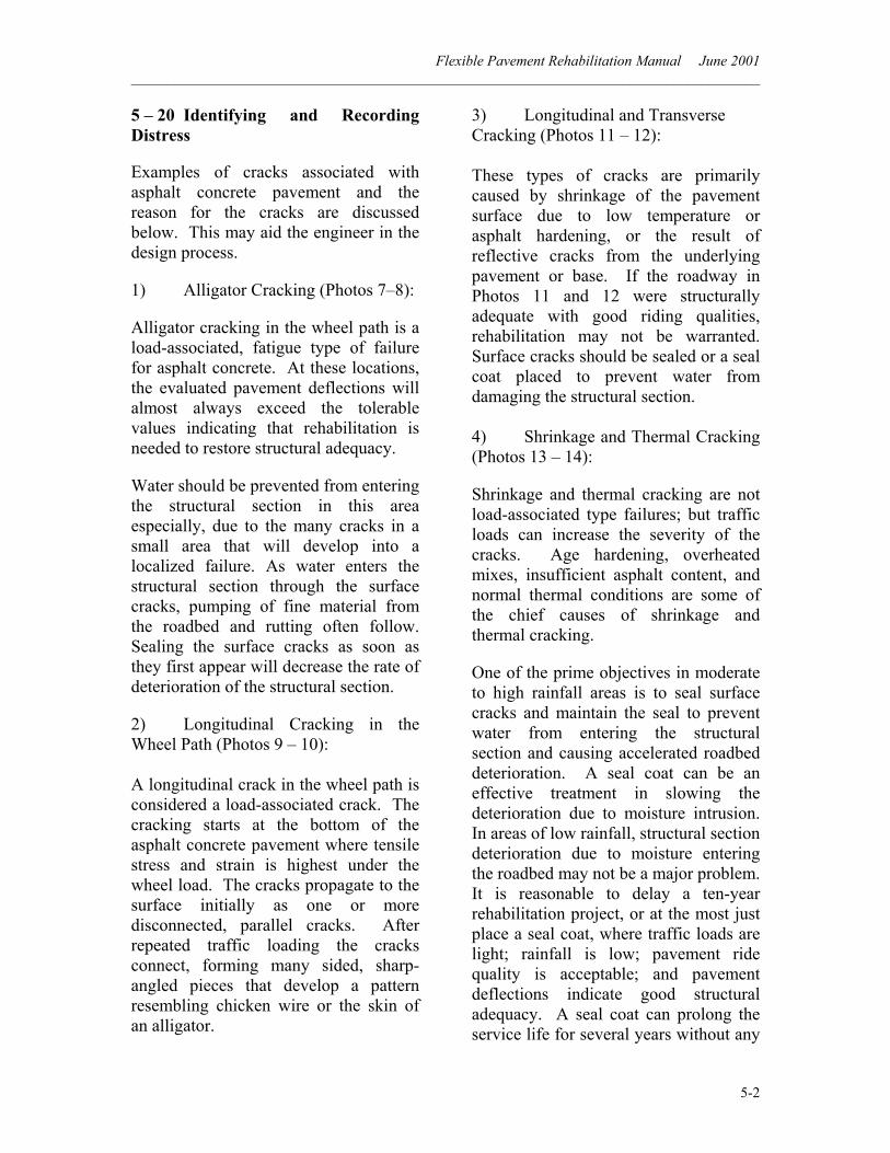
Flexible Pavement Rehabilitation Manual June 2001 ______________________________________________________________________________________
5-2
5 – 20 Identifying and Recording Distress Examples of cracks associated with asphalt concrete pavement and the reason for the cracks are discussed below. This may aid the engineer in the design process.
1) Alligator Cracking (Photos 7–8):
Alligator cracking in the wheel path is a load-associated, fatigue type of failure for asphalt concrete. At these locations, the evaluated pavement deflections will almost always exceed the tolerable values indicating that rehabilitation is needed to restore structural adequacy.
Water should be prevented from entering the structural section in this area especially, due to the many cracks in a small area that will develop into a localized failure. As water enters the structural section through the surface cracks, pumping of fine material from the roadbed and rutting often follow. Sealing the surface cracks as soon as they first appear will decrease the rate of deterioration of the structural section.
2) Longitudinal Cracking in the Wheel Path (Photos 9 – 10): A longitudinal crack in the wheel path is considered a load-associated crack. The cracking starts at the bottom of the asphalt concrete pavement where tensile stress and strain is highest under the wheel load. The cracks propagate to the surface initially as one or more disconnected, parallel cracks. After repeated traffic loading the cracks connect, forming many sided, sharp-angled pieces that develop a pattern resembling chicken wire or the skin of an alligator.
3) Longitudinal and Transverse Cracking (Photos 11 – 12): These types of cracks are primarily caused by shrinkage of the pavement surface due to low temperature or asphalt hardening, or the result of reflective cracks from the underlying pavement or base. If the roadway in Photos 11 and 12 were structurally adequate with good riding qualities, rehabilitation may not be warranted. Surface cracks should be sealed or a seal coat placed to prevent water from damaging the structural section. 4) Shrinkage and Thermal Cracking (Photos 13 – 14):
Shrinkage and thermal cracking are not load-associated type failures; but traffic loads can increase the severity of the cracks. Age hardening, overheated mixes, insufficient asphalt content, and normal thermal conditions are some of the chief causes of shrinkage and thermal cracking.
One of the prime objectives in moderate to high rainfall areas is to seal surface cracks and maintain the seal to prevent water from entering the structural section and causing accelerated roadbed deterioration. A seal coat can be an effective treatment in slowing the deterioration due to moisture intrusion. In areas of low rainfall, structural section deterioration due to moisture entering the roadbed may not be a major problem. It is reasonable to delay a ten-year rehabilitation project, or at the most just place a seal coat, where traffic loads are light; rainfall is low; pavement ride quality is acceptable; and pavement deflections indicate good structural adequacy. A seal coat can prolong the service life for several years without any
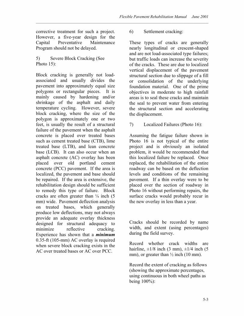
Flexible Pavement Rehabilitation Manual June 2001 ______________________________________________________________________________________
5-3
corrective treatment for such a project. However, a five-year design for the Capital Preventative Maintenance Program should not be delayed.
5) Severe Block Cracking (See Photo 15): Block cracking is generally not load-associated and usually divides the pavement into approximately equal size polygons or rectangular pieces. It is mainly caused by hardening and/or shrinkage of the asphalt and daily temperature cycling. However, severe block cracking, where the size of the polygon is approximately one or two feet, is usually the result of a structural failure of the pavement when the asphalt concrete is placed over treated bases such as cement treated base (CTB), lime treated base (LTB), and lean concrete base (LCB). It can also occur when an asphalt concrete (AC) overlay has been placed over old portland cement concrete (PCC) pavement. If the area is localized, the pavement and base should be repaired. If the area is extensive, the rehabilitation design should be sufficient to remedy this type of failure. Block cracks are often greater than ¼ inch (5 mm) wide. Pavement deflection analysis on treated bases, which generally produce low deflections, may not always provide an adequate overlay thickness designed for structural adequacy to minimize reflective cracking. Experience has shown that a minimum 0.35-ft (105-mm) AC overlay is required when severe block cracking exists in the AC over treated bases or AC over PCC.
6) Settlement cracking: These types of cracks are generally nearly longitudinal or crescent-shaped and are not load-associated type failures; but traffic loads can increase the severity of the cracks. These are due to localized vertical displacement of the pavement structural section due to slippage of a fill or consolidation of the underlying foundation material. One of the prime objectives in moderate to high rainfall areas is to seal these cracks and maintain the seal to prevent water from entering the structural section and accelerating the displacement.
7) Localized Failures (Photo 16): Assuming the fatigue failure shown in Photo 16 is not typical of the entire project and is obviously an isolated problem, it would be recommended that this localized failure be replaced. Once replaced, the rehabilitation of the entire roadway can be based on the deflection levels and conditions of the remaining pavement. If a thin overlay were to be placed over the section of roadway in Photo 16 without performing repairs, the surface cracks would probably recur in the new overlay in less than a year.
Cracks should be recorded by name width, and extent (using percentages) during the field survey.
Record whether crack widths are hairline, ±1/8 inch (3 mm), ±1/4 inch (5 mm), or greater than ½ inch (10 mm).
Record the extent of cracking as follows (showing the approximate percentages, using continuous in both wheel paths as being 100%):
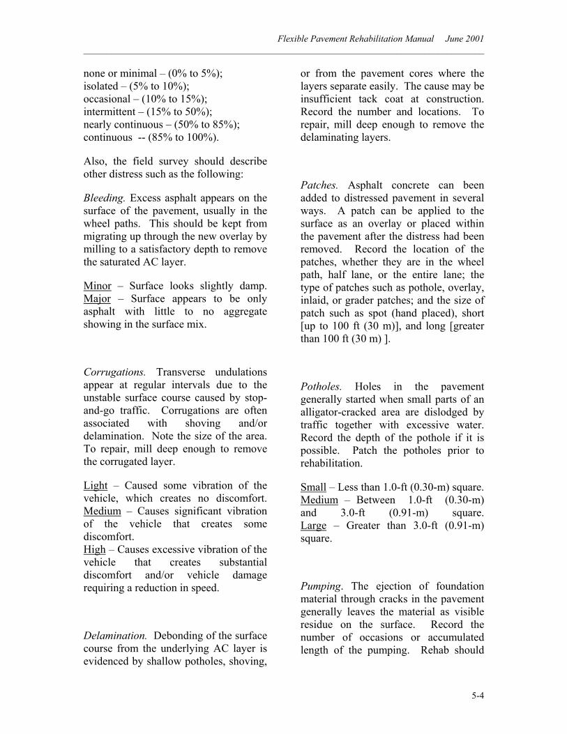
Flexible Pavement Rehabilitation Manual June 2001 ______________________________________________________________________________________
5-4
none or minimal – (0% to 5%); isolated – (5% to 10%); occasional – (10% to 15%); intermittent – (15% to 50%); nearly continuous – (50% to 85%); continuous -- (85% to 100%).
Also, the field survey should describe other distress such as the following:
Bleeding. Excess asphalt appears on the surface of the pavement, usually in the wheel paths. This should be kept from migrating up through the new overlay by milling to a satisfactory depth to remove the saturated AC layer.
Minor – Surface looks slightly damp. Major – Surface appears to be only asphalt with little to no aggregate showing in the surface mix.
Corrugations. Transverse undulations appear at regular intervals due to the unstable surface course caused by stop-and-go traffic. Corrugations are often associated with shoving and/or delamination. Note the size of the area. To repair, mill deep enough to remove the corrugated layer.
Light – Caused some vibration of the vehicle, which creates no discomfort. Medium – Causes significant vibration of the vehicle that creates some discomfort. High – Causes excessive vibration of the vehicle that creates substantial discomfort and/or vehicle damage requiring a reduction in speed.
Delamination. Debonding of the surface course from the underlying AC layer is evidenced by shallow potholes, shoving,
or from the pavement cores where the layers separate easily. The cause may be insufficient tack coat at construction. Record the number and locations. To repair, mill deep enough to remove the delaminating layers.
Patches. Asphalt concrete can been added to distressed pavement in several ways. A patch can be applied to the surface as an overlay or placed within the pavement after the distress had been removed. Record the location of the patches, whether they are in the wheel path, half lane, or the entire lane; the type of patches such as pothole, overlay, inlaid, or grader patches; and the size of patch such as spot (hand placed), short [up to 100 ft (30 m)], and long [greater than 100 ft (30 m) ].
Potholes. Holes in the pavement generally started when small parts of an alligator-cracked area are dislodged by traffic together with excessive water. Record the depth of the pothole if it is possible. Patch the potholes prior to rehabilitation.
Small – Less than 1.0-ft (0.30-m) square. Medium – Between 1.0-ft (0.30-m) and 3.0-ft (0.91-m) square. Large – Greater than 3.0-ft (0.91-m) square.
Pumping. The ejection of foundation material through cracks in the pavement generally leaves the material as visible residue on the surface. Record the number of occasions or accumulated length of the pumping. Rehab should
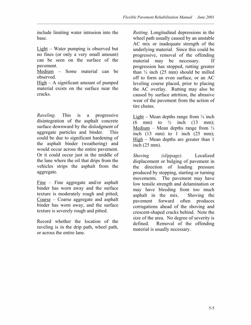
Flexible Pavement Rehabilitation Manual June 2001 ______________________________________________________________________________________
5-5
include limiting water intrusion into the base.
Light – Water pumping is observed but no fines (or only a very small amount) can be seen on the surface of the pavement. Medium – Some material can be observed. High – A significant amount of pumped material exists on the surface near the cracks.
Raveling. This is a progressive disintegration of the asphalt concrete surface downward by the dislodgment of aggregate particles and binder. This could be due to significant hardening of the asphalt binder (weathering) and would occur across the entire pavement. Or it could occur just in the middle of the lane where the oil that drips from the vehicles strips the asphalt from the aggregate.
Fine – Fine aggregate and/or asphalt binder has worn away and the surface texture is moderately rough and pitted; Coarse – Coarse aggregate and asphalt binder has worn away, and the surface texture is severely rough and pitted.
Record whether the location of the raveling is in the drip path, wheel path, or across the entire lane.
Rutting. Longitudinal depressions in the wheel path usually caused by an unstable AC mix or inadequate strength of the underlying material. Since this could be progressive, removal of the offending material may be necessary. If progression has stopped, rutting greater than ½ inch (25 mm) should be milled off to form an even surface, or an AC leveling course placed, prior to placing the AC overlay. Rutting may also be caused by surface attrition, the abrasive wear of the pavement from the action of tire chains.
Light – Mean depths range from ¼ inch (6 mm) to ½ inch (13 mm); Medium – Mean depths range from ½ inch (13 mm) to 1 inch (25 mm); High – Mean depths are greater than 1 inch (25 mm).
Shoving (slippage). Localized displacement or bulging of pavement in the direction of loading pressure produced by stopping, starting or turning movements. The pavement may have low tensile strength and delamination or may have bleeding from too much asphalt in the mix. Shoving the pavement forward often produces corrugations ahead of the shoving and crescent-shaped cracks behind. Note the size of the area. No degree of severity is defined. Removal of the offending material is usually necessary.
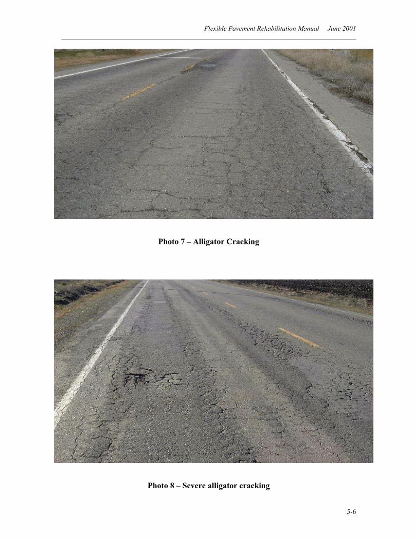
Flexible Pavement Rehabilitation Manual June 2001 ______________________________________________________________________________________
5-6
Photo 7 – Alligator Cracking
Photo 8 – Severe alligator cracking
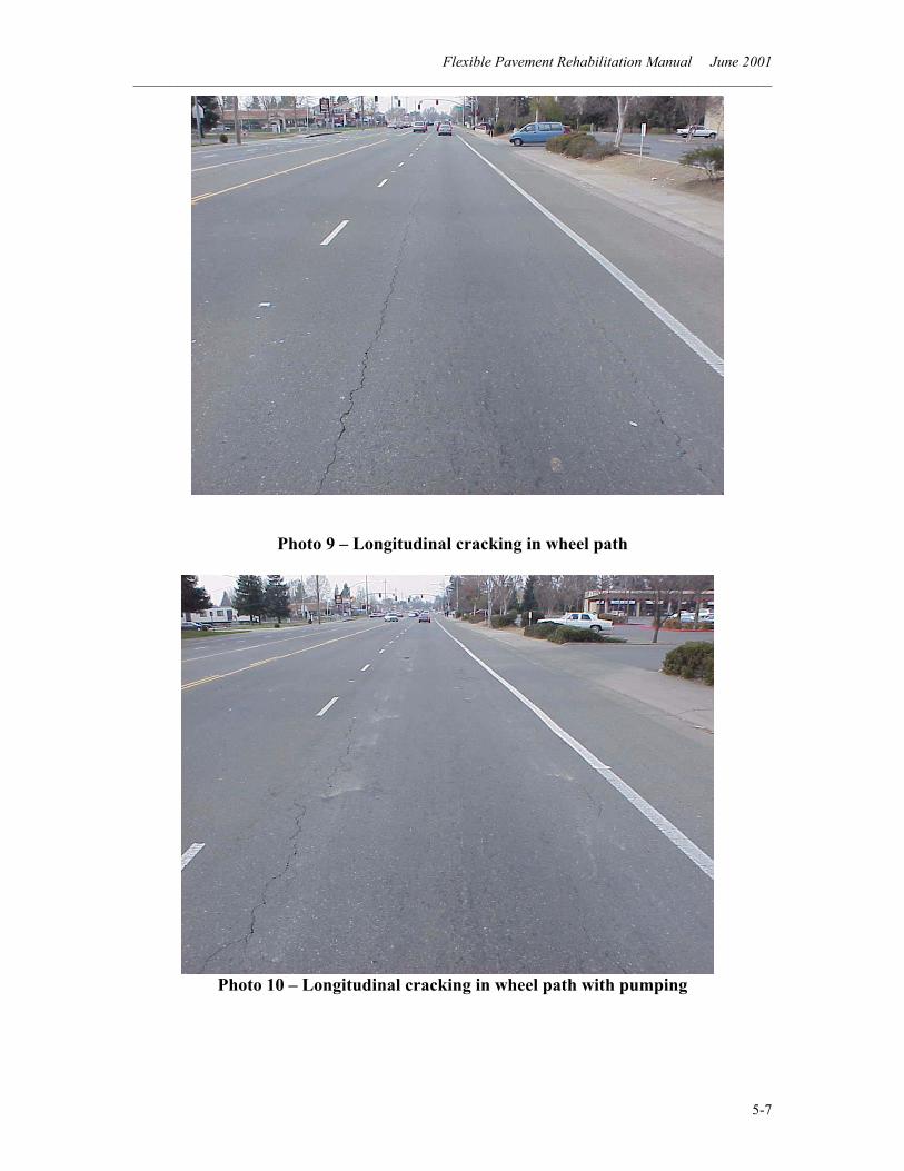
Flexible Pavement Rehabilitation Manual June 2001 ______________________________________________________________________________________
5-7
Photo 9 – Longitudinal cracking in wheel path
Photo 10 – Longitudinal cracking in wheel path with pumping
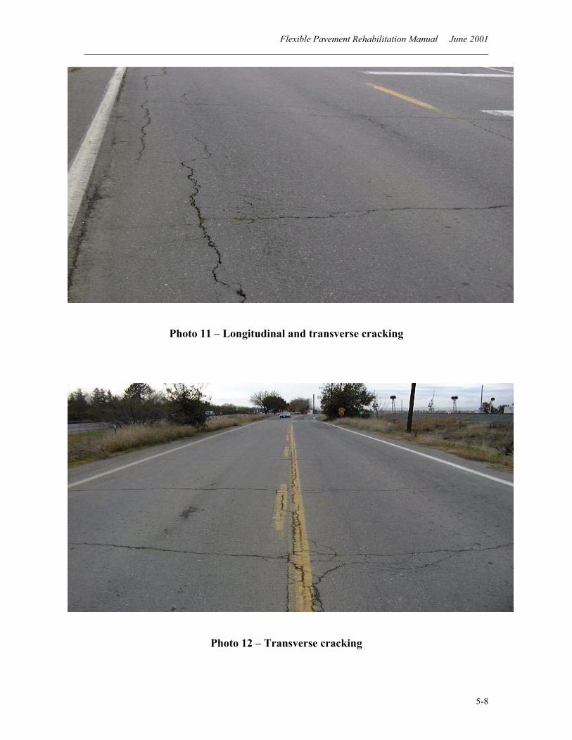
Flexible Pavement Rehabilitation Manual June 2001 ______________________________________________________________________________________
5-8
Photo 11 – Longitudinal and transverse cracking
Photo 12 – Transverse cracking
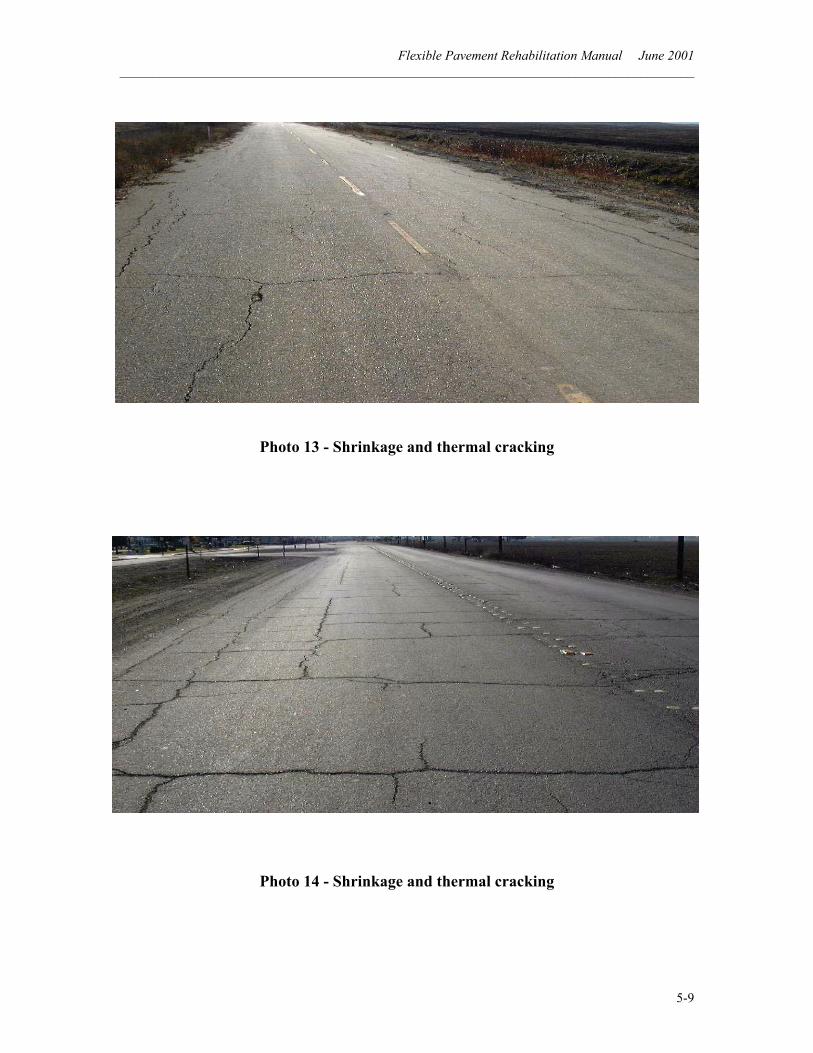
Flexible Pavement Rehabilitation Manual June 2001 ______________________________________________________________________________________
5-9
Photo 13 - Shrinkage and thermal cracking
Photo 14 - Shrinkage and thermal cracking
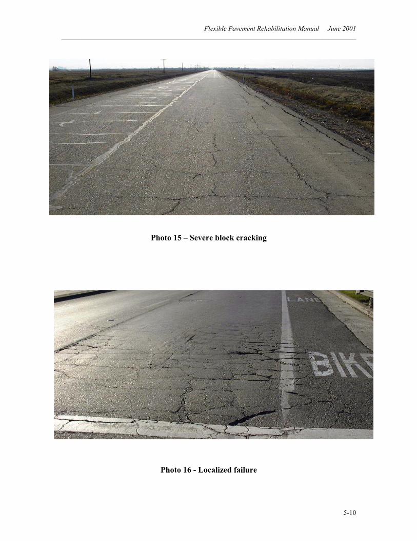
Flexible Pavement Rehabilitation Manual June 2001 ______________________________________________________________________________________
5-10
Photo 15 – Severe block cracking
Photo 16 - Localized failure
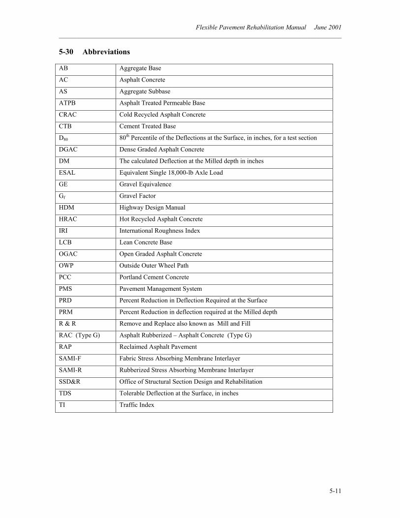
Flexible Pavement Rehabilitation Manual June 2001 ______________________________________________________________________________________
5-11
5-30 Abbreviations
AB Aggregate Base
AC Asphalt Concrete
AS Aggregate Subbase
ATPB Asphalt Treated Permeable Base
CRAC Cold Recycled Asphalt Concrete
CTB Cement Treated Base
D80 80th Percentile of the Deflections at the Surface, in inches, for a test section
DGAC Dense Graded Asphalt Concrete
DM The calculated Deflection at the Milled depth in inches
ESAL Equivalent Single 18,000-lb Axle Load
GE Gravel Equivalence
Gf Gravel Factor
HDM Highway Design Manual
HRAC Hot Recycled Asphalt Concrete
IRI International Roughness Index
LCB Lean Concrete Base
OGAC Open Graded Asphalt Concrete
OWP Outside Outer Wheel Path
PCC Portland Cement Concrete
PMS Pavement Management System
PRD Percent Reduction in Deflection Required at the Surface
PRM Percent Reduction in deflection required at the Milled depth
R & R Remove and Replace also known as Mill and Fill
RAC (Type G) Asphalt Rubberized – Asphalt Concrete (Type G)
RAP Reclaimed Asphalt Pavement
SAMI-F Fabric Stress Absorbing Membrane Interlayer
SAMI-R Rubberized Stress Absorbing Membrane Interlayer
SSD&R Office of Structural Section Design and Rehabilitation
TDS Tolerable Deflection at the Surface, in inches
TI Traffic Index
Flexible Pavement Rehabilitation Manual June 2001 ______________________________________________________________________________________
5-12
5-40 Definitions
Alligator Cracking. Interconnected or interlaced load associated (fatigue) cracks in asphalt concrete pavement forming a series of small polygons that resemble the typical pattern of an alligator’s skin. Asphalt Treated Permeable Base (ATPB). A highly permeable open-graded mixture of crushed coarse aggregate and asphalt binder placed as the base layer to assure adequate drainage of the structural section, as well as structural support. Base. A layer of selected, processed, and/or treated aggregate material of planned thickness and quality placed immediately below the pavement and above the subbase or basement soil to support the pavement. Basement Material. The material in excavation or embankments underlying the lowest layer of subbase, base, pavement surfacing or other specified layer which is to be placed. Basement Soil. See Basement Material. Bleeding. Also known as flushing, excess asphalt appears on the surface of the pavement, usually in the wheel paths. Accumulation with time may reduce skid resistance. Block Cracking. Interconnected cracks, which form a series of large polygons, usually with sharp corners or angles. Block cracking appears on flexible pavement but is not load associated. Cement Treated Permeable Base (CTPB). A highly permeable open-
graded mixture of coarse aggregate, portland cement, and water placed as the base layer to provide adequate drainage of the structural section, as well as structural support. Chip Seal. A high viscosity asphaltic emulsion surface coat, which incorporates rolled in rock screenings (chips) over an asphalt concrete pavement, as preventive maintenance, to extend the service life. Cold Recycling. The rehabilitation of asphalt concrete pavement in place, without the application of heat, by milling and mixing with new binder and/or rejuvenating agents. Composite Pavement. A pavement structure or structural section composed of an asphalt concrete wearing surface and portland cement concrete (PCC) slab; an asphalt concrete overlay on a PCC slab is also referred to as a composite pavement. Corrugations. Also known as “wash board,” transverse undulations appear at regular intervals due to the unstable surface course. This consists of alternating crests and valleys less that 2 feet apart and usually occurs where vehicles stop and start. Crack Seals. Pourable, or extrudable, materials that are placed in cracks to deter the entry of water and incompressible materials, and to retard the crack from reflecting up into the asphalt concrete overlay. Cushion Course. The layer, generally an aggregate base material, that is placed over an existing pavement to increase the profile grade and give additional
Flexible Pavement Rehabilitation Manual June 2001 ______________________________________________________________________________________
5-13
structural support before placing the new asphalt concrete pavement. Delamination. A separation (debonding) of two layers of asphalt concrete generally due to insufficient paint binder during construction. It causes the two layers to act independently from each other. Dense Graded Asphalt Concrete (DGAC). A uniformly graded asphalt concrete mixture (aggregate and paving asphalt) containing a small percentage of voids, used primarily as a surface layer to provide the structural strength needed to distribute loads to underlying layers of the structural section. Design Period. The period of time that an initially constructed or rehabilitated pavement structural section is designed to perform before reaching its terminal serviceability or a condition that requires major rehabilitation or reconstruction; this is also referred to as the performance period. Because of the many independent variables involved, the service life before major maintenance or rehabilitation is required may actually be considerably longer or shorter. Drip Path Ravel. Progressive disintegration of the surface between wheel paths on asphalt concrete pavement, caused by oil and fuel dripping from vehicles. This is most prevalent adjacent to intersections where vehicles slow and stop. Edge Drain System. A drainage system, consisting of a slotted plastic collector pipe encapsulated in treated permeable material and a filter fabric barrier, with unslotted plastic pipe vents, outlets, and
cleanouts, designed to drain the structural section of both rigid and flexible pavements. Embankment. A prism of earth that is constructed from excavated or borrowed natural soil and/or rock, extending from original ground to the grading plane, and designed to provide a stable support for the pavement structural section. Equivalent Single Axle Loads (ESAL’s). Summation of equivalent 18000-lb (80- kN) single axle loads used to convert mixed traffic to design traffic for the design period. Flexible Pavement. A traffic load carrying system that is made up of one or more layers that are designed to transmit and distribute that loading to the underlying roadbed material. The highest quality layer is the surface course, (generally asphalt concrete) which is usually underlain by a lesser quality base, and in turn a subbase. It is called flexible because it can tolerate deflection bending under heavy loads. Fog Seal. A combination of mixing-type asphaltic emulsion and water which is applied to the surface of asphalt concrete pavement to seal the surface, primarily used for pavement maintenance. Grading Plane. The surface of the basement material upon which the lowest layer of subbase, base, pavement surfacing, or other specified layer, is placed. Hot Recycling. The use of reclaimed asphalt concrete pavement which is combined with virgin aggregates, asphalt, and sometimes rejuvenating agents at a central hot-mix plant and
Flexible Pavement Rehabilitation Manual June 2001 ______________________________________________________________________________________
5-14
placed in the structural section in lieu of all new materials. Lean Concrete Base. Mixture of aggregate, portland cement, water, and optional admixtures, primarily used as a base for portland cement concrete pavement. Leveling Course. The layer, generally of AC or other treated or processed material, that is placed over the rough or undulating surface of an existing pavement, structure deck, or other surface to improve the surface profile or ride quality before placement of subsequent layers. Lime Treatment. The mixing of lime with native or embankment materials to increase the strength (R-value) of the material which supports the pavement structural section. Localized Failure. A pavement that is within a definite locality that exhibits loose and/or spalling pieces of asphalt concrete pavement, brought on by alligator cracking, possibly with rutting and insufficient base support. Longitudinal Cracking. Cracks or breaks in flexible or rigid pavement, which are approximately parallel to the pavement, center line. Low-Volume Road. A roadway generally subjected to low levels of traffic; in the AASHTO Design Guide, structural design is based on a range of 80 kN ESAL’s from 50 000 to 1 000 000 for flexible and rigid pavements, and from 10 000 to 100 000 for aggregate-surfaced roads.
Maintenance. The preservation of the entire roadway, including pavement surface and structural section, shoulders, roadsides, structures, and such traffic control devices as are necessary for its safe and efficient utilization. Open Graded Asphalt Concrete (OGAC). An open graded mixture of aggregate and a relatively high asphalt content, which provides good skid resistance and a high permeability. OGAC is designed to accommodate rapid surface drainage and minimize the potential of hydroplaning while at the same time providing an effective seal of the underlying asphalt concrete pavement. Outside Wheel Path (OWP). The vehicle tire path closest to the outside edge of pavement. Deflection measurements are usually made in the outside wheel path. Overlay. An overlay is a layer, usually asphalt concrete, placed on existing asphalt or portland cement concrete pavement to restore ride quality, to increase structural strength (load carrying capacity), and to extend the service life. Patches. Corrections to damaged pavement by adding asphalt concrete. It could be applied to the surface or placed after the distress has been removed. Pavement. The surface layer of the structural section that carries traffic. Except for special or experimental surface layers, the pavement is either portland cement concrete or asphalt concrete. The asphalt concrete layer may include up to a 30-mm layer of OGAC.
Flexible Pavement Rehabilitation Manual June 2001 ______________________________________________________________________________________
5-15
Pavement Management System (PMS). A management system, which was developed by Caltrans, to assess the condition of pavement, biennially, on the entire California State Highway System, and to prioritize and program the rehabilitation of pavement consistent with available funding. Pavement Performance. The trend of serviceability with load applications. Pavement Rehabilitation. Work undertaken to extend the service life of an existing facility. This includes placement of additional surfacing and/or other work necessary to return an existing roadway, including shoulders, to a condition of structural or functional adequacy, for a minimum period of 10 years. This might include the partial or complete removal and replacement of portions of the pavement structural section. Pavement Reinforcing Fabric (PRF or SAMI-F). A stress absorbing membrane interlayer that is a nonwoven, bonded-fiber, engineering grade synthetic fabric. It is used by Caltrans in asphalt concrete overlays primarily to minimize surface water infiltration and retard reflective cracking through the overlay, from cracks or joints in the existing pavement. Pavement Structure. See Structural Section Pavement Surfacing. See Surface Course Pot Holes. Bowl-shaped holes of various sizes in the pavement that generally start when small parts of an alligator-cracked area are dislodged by traffic together with excessive moisture. The depth may
be only to the next lift of asphalt concrete or it may extend into the base. Prepared Roadbed. In-place soils compacted or stabilized according to provisions of applicable specifications. Present Serviceability Index (PSI). A term from the AASHTO Design Guide; a number derived by formula for estimating the serviceability rating from measurements of certain physical features of the pavement. Not used directly by Caltrans for pavement evaluation but conversion is made in PMS, for comparison. Preventive Maintenance. Typically, capital outlay work performed to preserve the existing pavement structural section utilizing strategies that extend pavement service life for 5 years (i.e.: for AC pavements, “thick blanket” overlays; for PCC pavements, grinding, slab replacement, etc.). Prime Coat. (Sometimes called tack coat.) The application of a low viscosity liquid bituminous material to an absorbent surface (preparatory to placing subsequent structural section layers or PRF) for the purpose of hardening or toughening the surface and promoting adhesion between it and the superimposed constructed layer or PRF interlayer. Pumping. The ejection of foundation material, either wet or dry, through cracks resulting from vertical movements of the pavement under traffic. This phenomenon is especially pronounced with saturated structural sections.
Flexible Pavement Rehabilitation Manual June 2001 ______________________________________________________________________________________
5-16
Raveling. Gradual degradation of the pavement surface. Weathering or stripping of the asphalt from the aggregates, along with action of the tires, causes separation of the aggregates and asphalt. Stripping may be accomplished by an excessive amount of water with the tire action, or by oil and gas dripping from passing vehicles (drip track raveling). Raveling in the wheel path may also be caused by abrasive chain wear. Reflective Cracking. Generally occurs on pavements that have an asphalt concrete surface over jointed portland cement concrete or a cement treated base. This is mainly caused by movement of the PCC or CTB because of thermal and moisture changes. Resurfacing. A supplemental surface layer or replacement layer placed on an existing pavement to restore its riding qualities or to increase its structural (load carrying) strength. Rigid Pavement. Primarily portland cement concrete pavement, which distributes the superimposed axle loads over a relatively wide area of underlying structural section layers and soil because of its rigidity and high modulus of elasticity. Roadbed. The roadbed is that area between the intersection of the upper surface of the roadway and the side slopes or curb lines. The roadbed rises in elevation as each increment or layer of subbase, base, surfacing or pavement is placed. Where the medians are so wide as to include areas of undisturbed land, a divided highway is considered as including two separate roadbeds.
Roadbed Material. Also referred to as basement soil or basement material, the material below the grading plane in cuts and embankments, extending to such depths as affect the support of the pavement structure or structural section. Rubberized Asphalt. A mixture of paving asphalt combined with specified percentages of granulated reclaimed rubber for use as the binder in asphalt concrete and in stress absorbing membrane interlayers (SAMI-R) within or under asphalt concrete overlays. Primary applications where benefits appear to be significant are for providing more resilient and more durable wearing surface for overlays, to retard reflective cracking and overlays on pavement exposed to wear by tire chains. Rubberized asphalt joint sealant is used to keep out incompressible materials and retard surface water infiltration. Rubberized Asphalt Concrete Type G (RAC Type G). Also known as Asphalt Rubber Hot Mix – Gap Graded. A gap graded mixture of crushed coarse and fine aggregate, and of paving asphalt that are combined with specified percentages of granulated (crumb) reclaimed rubber. Generally, the crumb rubber is blended and partially reacted with asphalt cement prior to mixing with the aggregate in a hot mix plant. Primary applications, where benefits appear to be significant, are for providing more resilient and more durable wearing surface for overlays, to retard reflective cracking and overlays on pavement exposed to wear by tire chains. Rutting. Longitudinal depressions that develop in the wheel paths of flexible pavement under traffic. Unstable asphalt
Flexible Pavement Rehabilitation Manual June 2001 ______________________________________________________________________________________
5-17
concrete pavement or inadequate strength of the underlying foundation most often causes this permanent and sometimes progressive deformation. Rutting may also occur due to chain or studded tire abrasion or raveling. R-value. Resistance value of treated or untreated soil or aggregate as determined by the stabilometer test (California Test 301). This is a measure of the supporting strength of the basement soil and subsequent layers used in the design of pavement structural sections. Seal Coat. A bituminous coating, with or without aggregate, applied to the surface of a pavement for the purpose of waterproofing, preserving, or rejuvenating a cracked or raveling bituminous surface, or to provide increased skid resistance or resistance to abrasion by traffic. Serviceability. The ability at time of observation of a pavement to serve traffic (autos and trucks) which use the facility. Settlement. Localized vertical displacement of the pavement structural section due to slippage of a fill or consolidation of the underlying foundation, often resulting in pavement cracking and a poor ride quality. Shoulder Backing. A material that is placed adjacent to the outside edge of the shoulder surfacing to protect the edge from spalling, and to provide edge support. Shoving. Localized displacement or bulging of pavement in the direction of loading pressure produced by stopping, starting or turning movements. The
pavement may have low tensile strength and delamination or may have bleeding from too much asphalt in the mix. Shoving the pavement forward often produces corrugations ahead of the shoving and crescent-shaped cracks behind. Single Axle Load. The total load transmitted by all wheels whose centers may be included between two parallel transverse vertical planes 1.016 m (40 inches) apart, extending across the full width of the vehicle. Slurry Seal. A mixture of mixing-type asphaltic emulsion, fine mineral aggregate and water proportioned, mixed and spread primarily on asphalt concrete pavement for maintenance purposes. Spalling. Cracking, breaking, or chipping of the edge of a crack in which small portions of the pavement are dislodged. Spalling is caused primarily by nonuniform support in conjunction with vertical movement due to wheel loads or incompressibles confined in the opening. Stress Absorbing Membrane Interlayer (SAMI). An interlayer placed within or at the bottom of an asphalt concrete overlay or layer to retard reflective cracking and prevent water intrusion. Examples include a rubberized chip seal interlayer (SAMI-R) or pavement reinforcing fabric (SAMI-F). Stripping. The loss of the adhesive bond between asphalt cement and aggregate, most often caused by the presence of water in asphalt concrete, which may result in raveling, loss of stability and load carrying capacity of the asphalt concrete pavement or treated base.
Flexible Pavement Rehabilitation Manual June 2001 ______________________________________________________________________________________
5-18
Structural Section. The planned, engineering-designed layers of specified materials (normally consisting of subbase, base, and pavement surface) placed over the basement soil to support the traffic loads anticipated to be accumulated and applied during the design period. The structural section is also commonly called the pavement structural section. Structural Section Drainage System. A drainage system used for both asphalt and portland cement concrete pavements consisting of a treated permeable base layer and a collector system which includes a slotted plastic pipe encapsulated in treated permeable material and a filter fabric barrier with unslotted plastic pipe as vents, outlets and cleanouts to rapidly drain the pavement structural section. Subbase. A layer of aggregate of designed thickness and specified quality placed on the basement soils as the foundation for a base. Subgrade. That portion of the roadbed on which pavement surfacing, base, subbase, or a layer of any other material is placed. Surface Attrition (“Abrasion”). Abnormal surface abrasion wear of pavement, resulting from either a poor quality surface or exposure to abnormal abrasive action (such as tire chains and sanding materials) or both. Surface Course. The top layer of AC pavement. It is also sometimes called the “wearing course”.
Surface Polish. The loss of the original pavement surface texture due to traffic. Surface Recycling. In-place heating of the surface of asphalt concrete pavement followed by scarification, remixing, and compaction, generally to a depth of about 20 mm. This is considered to be a maintenance procedure. Tack Coat (Paint Binder). The application of bituminous material to an existing surface to provide bond between the superimposed construction and the existing surface. Tandem Axle Load. The total load transmitted to the pavement by two consecutive axles whose centers may be included between parallel vertical planes spaced more than 1.016 m (40 inches) and not more than 2.438 m (96 inches) apart, extending across the full width of the vehicle. Transverse Cracking. Cracks in asphalt concrete pavement approximately at right angles to the centerline most often created by thermal forces exceeding the tensile strength of the asphalt concrete. Weathering. Gradual degradation of the pavement surface. Oxidation and hardening of the asphalt cause separation from the aggregates, along with action of the tires, result in surface raveling. Wearing Course. See Surface Course.
Flexible Pavement Rehabilitation Manual June 2001 ______________________________________________________________________________________
5-19
5-50 Bibliography 1. Hveem, F. N., “Pavement Deflections and Fatigue Failures,” Highway Research
Board Bulletin 114, 1955. 2. Zube, E. and Forsyth, R. A., “Flexible Pavement Maintenance Requirements as
Determined By Deflection Measurements,” Proceedings, 45th Annual Meeting of the Highway Research Board, January 1966.
3. Bushey, Roy W.; Baumeister,K. L.; Matthews, James A.; Sherman, George B.;
“Structural Overlays for Pavement Rehabilitation,” Interim Report, California Department of Transportation, July 1974.
4. State of California, Department of Transportation, Caltrans Standard Test Methods,
Vol. 2, California Test 356. 5. “Asphalt Concrete Overlay Design Manual,” California Department of
Transportation, January 1979. 6. Mann, Gary W.; Matthews, J. A.; Webster J. T.; “An Evaluation of the Current
California Method To Determine Asphalt Concrete Overlay Thickness,” California Department of Transportation, June 1980.
7. Hannon, J.B.; Mason, P. E.; Boerger, E.; “Determine Gravel Equivalent Factor For
Cold Recycled Asphalt Pavement,” Final Report of Minor Research Study, California Department of Transportation, Office of Transportation, August 1988.
8. State of California, Department of Transportation, “Chapter 600, Design of the
Pavement Structural Section,” Highway Design Manual, Fifth Edition, Sacramento, California.
9. State of California, Department of Transportation, “Standard Specifications, July
1999.”
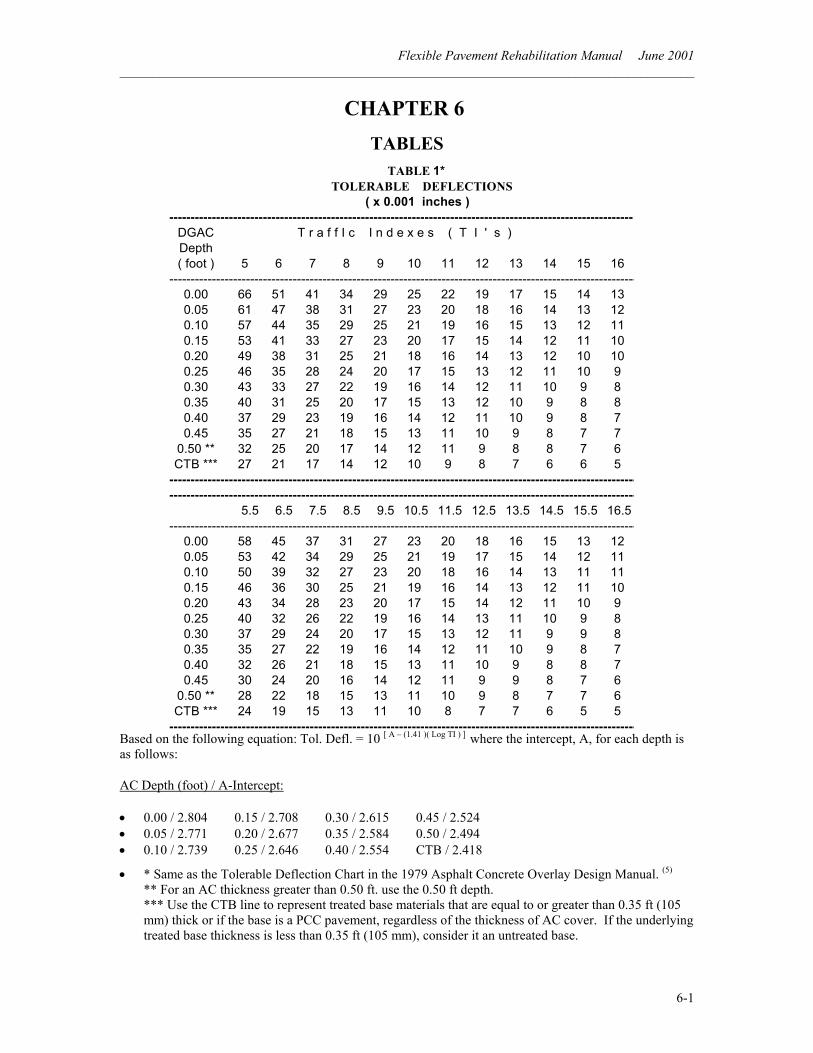
Flexible Pavement Rehabilitation Manual June 2001 ______________________________________________________________________________________
6-1
CHAPTER 6 TABLES
Based on the following equation: Tol. Defl. = 10 [ A – (1.41 )( Log TI ) ] where the intercept, A, for each depth is as follows:
AC Depth (foot) / A-Intercept:
• 0.00 / 2.804 0.15 / 2.708 0.30 / 2.615 0.45 / 2.524 • 0.05 / 2.771 0.20 / 2.677 0.35 / 2.584 0.50 / 2.494 • 0.10 / 2.739 0.25 / 2.646 0.40 / 2.554 CTB / 2.418
• * Same as the Tolerable Deflection Chart in the 1979 Asphalt Concrete Overlay Design Manual. (5)
** For an AC thickness greater than 0.50 ft. use the 0.50 ft depth. *** Use the CTB line to represent treated base materials that are equal to or greater than 0.35 ft (105 mm) thick or if the base is a PCC pavement, regardless of the thickness of AC cover. If the underlying treated base thickness is less than 0.35 ft (105 mm), consider it an untreated base.
TABLE 1*TOLERABLE DEFLECTIONS
( x 0.001 inches ) -------------------------------------------------------------------------------------------------------------
DGAC T r a f f I c I n d e x e s ( T I ' s )Depth( foot ) 5 6 7 8 9 10 11 12 13 14 15 16
--------------------------------------------------------------------------------------------------------------0.00 66 51 41 34 29 25 22 19 17 15 14 130.05 61 47 38 31 27 23 20 18 16 14 13 120.10 57 44 35 29 25 21 19 16 15 13 12 110.15 53 41 33 27 23 20 17 15 14 12 11 100.20 49 38 31 25 21 18 16 14 13 12 10 100.25 46 35 28 24 20 17 15 13 12 11 10 90.30 43 33 27 22 19 16 14 12 11 10 9 80.35 40 31 25 20 17 15 13 12 10 9 8 80.40 37 29 23 19 16 14 12 11 10 9 8 70.45 35 27 21 18 15 13 11 10 9 8 7 7
0.50 ** 32 25 20 17 14 12 11 9 8 8 7 6CTB *** 27 21 17 14 12 10 9 8 7 6 6 5
-------------------------------------------------------------------------------------------------------------- --------------------------------------------------------------------------------------------------------------
5.5 6.5 7.5 8.5 9.5 10.5 11.5 12.5 13.5 14.5 15.5 16.5 --------------------------------------------------------------------------------------------------------------
0.00 58 45 37 31 27 23 20 18 16 15 13 120.05 53 42 34 29 25 21 19 17 15 14 12 110.10 50 39 32 27 23 20 18 16 14 13 11 110.15 46 36 30 25 21 19 16 14 13 12 11 100.20 43 34 28 23 20 17 15 14 12 11 10 90.25 40 32 26 22 19 16 14 13 11 10 9 80.30 37 29 24 20 17 15 13 12 11 9 9 80.35 35 27 22 19 16 14 12 11 10 9 8 70.40 32 26 21 18 15 13 11 10 9 8 8 70.45 30 24 20 16 14 12 11 9 9 8 7 6
0.50 ** 28 22 18 15 13 11 10 9 8 7 7 6CTB *** 24 19 15 13 11 10 8 7 7 6 5 5
--------------------------------------------------------------------------------------------------------------
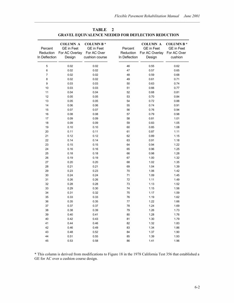
Flexible Pavement Rehabilitation Manual June 2001 ______________________________________________________________________________________
6-2
* This column is derived from modifications to Figure 18 in the 1978 California Test 356 that established a GE for AC over a cushion course design.
TABLE 2 GRAVEL EQUIVALENCE NEEDED FOR DEFLECTION REDUCTION
------------------------------------------------------------------------------------------------------------------------------------COLUMN A COLUMN B * COLUMN A COLUMN B *
Percent GE in Feet GE in Feet Percent GE in Feet GE in FeetReduction For AC Overlay For AC Over Reduction For AC Overlay For AC Over
In Deflection Design cushion course In Deflection Design cushion ----------------- --------------------- -------------------- ----------------- -------------------- --------------------
5 0.02 0.02 46 0.55 0.626 0.02 0.02 47 0.57 0.657 0.02 0.02 48 0.59 0.688 0.02 0.02 49 0.61 0.719 0.03 0.03 50 0.63 0.7410 0.03 0.03 51 0.66 0.7711 0.04 0.04 52 0.68 0.8112 0.05 0.05 53 0.70 0.8413 0.05 0.05 54 0.72 0.8814 0.06 0.06 55 0.74 0.9115 0.07 0.07 56 0.76 0.9416 0.08 0.08 57 0.79 0.9817 0.09 0.09 58 0.81 1.0118 0.09 0.09 59 0.83 1.0519 0.10 0.10 60 0.85 1.0820 0.11 0.11 61 0.87 1.1121 0.12 0.12 62 0.89 1.1522 0.14 0.14 63 0.91 1.1823 0.15 0.15 64 0.94 1.2224 0.16 0.16 65 0.96 1.2525 0.18 0.18 66 0.98 1.2826 0.19 0.19 67 1.00 1.3227 0.20 0.20 68 1.02 1.3528 0.21 0.21 69 1.04 1.3929 0.23 0.23 70 1.06 1.4230 0.24 0.24 71 1.09 1.4531 0.26 0.26 72 1.11 1.4932 0.28 0.28 73 1.13 1.5233 0.29 0.30 74 1.15 1.5634 0.31 0.32 75 1.17 1.5935 0.33 0.33 76 1.19 1.6236 0.35 0.35 77 1.22 1.6637 0.37 0.37 78 1.24 1.6938 0.38 0.39 79 1.26 1.7339 0.40 0.41 80 1.28 1.7640 0.42 0.43 81 1.30 1.7941 0.44 0.46 82 1.32 1.8342 0.46 0.49 83 1.34 1.8643 0.48 0.52 84 1.37 1.9044 0.51 0.55 85 1.39 1.9345 0.53 0.58 86 1.41 1.96
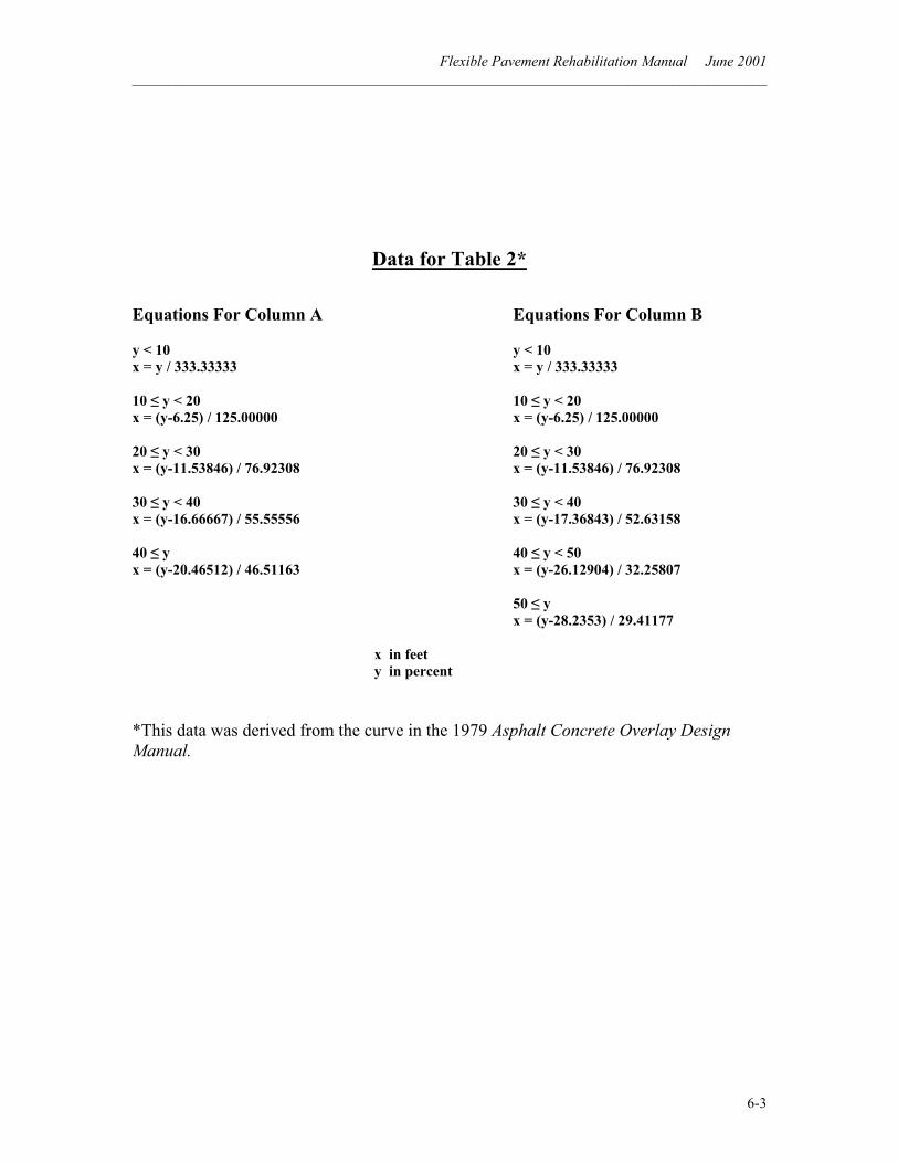
Flexible Pavement Rehabilitation Manual June 2001 ______________________________________________________________________________________
6-3
Data for Table 2*
Equations For Column A Equations For Column B y < 10 y < 10 x = y / 333.33333 x = y / 333.33333 10 ≤ y < 20 10 ≤ y < 20 x = (y-6.25) / 125.00000 x = (y-6.25) / 125.00000 20 ≤ y < 30 20 ≤ y < 30 x = (y-11.53846) / 76.92308 x = (y-11.53846) / 76.92308 30 ≤ y < 40 30 ≤ y < 40 x = (y-16.66667) / 55.55556 x = (y-17.36843) / 52.63158 40 ≤ y 40 ≤ y < 50 x = (y-20.46512) / 46.51163 x = (y-26.12904) / 32.25807 50 ≤ y x = (y-28.2353) / 29.41177 x in feet y in percent
*This data was derived from the curve in the 1979 Asphalt Concrete Overlay Design Manual.
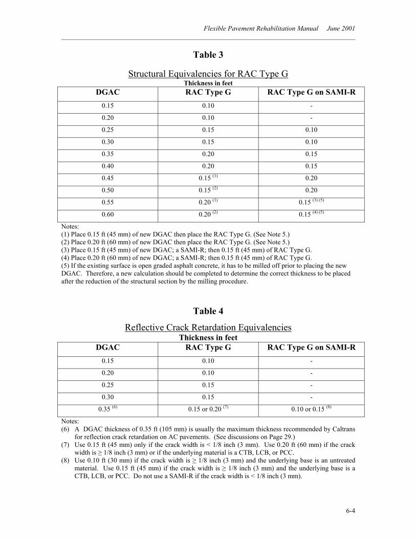
Flexible Pavement Rehabilitation Manual June 2001 ______________________________________________________________________________________
6-4
Table 3
Structural Equivalencies for RAC Type G Thickness in feet
DGAC RAC Type G RAC Type G on SAMI-R 0.15 0.10 -
0.20 0.10 -
0.25 0.15 0.10
0.30 0.15 0.10
0.35 0.20 0.15
0.40 0.20 0.15
0.45 0.15 (1) 0.20
0.50 0.15 (2) 0.20
0.55 0.20 (1) 0.15 (3) (5)
0.60 0.20 (2) 0.15 (4) (5)
Notes: (1) Place 0.15 ft (45 mm) of new DGAC then place the RAC Type G. (See Note 5.) (2) Place 0.20 ft (60 mm) of new DGAC then place the RAC Type G. (See Note 5.) (3) Place 0.15 ft (45 mm) of new DGAC; a SAMI-R; then 0.15 ft (45 mm) of RAC Type G. (4) Place 0.20 ft (60 mm) of new DGAC; a SAMI-R; then 0.15 ft (45 mm) of RAC Type G. (5) If the existing surface is open graded asphalt concrete, it has to be milled off prior to placing the new DGAC. Therefore, a new calculation should be completed to determine the correct thickness to be placed after the reduction of the structural section by the milling procedure.
Table 4
Reflective Crack Retardation Equivalencies Thickness in feet
DGAC RAC Type G RAC Type G on SAMI-R 0.15 0.10 -
0.20 0.10 -
0.25 0.15 -
0.30 0.15 -
0.35 (6) 0.15 or 0.20 (7) 0.10 or 0.15 (8)
Notes: (6) A DGAC thickness of 0.35 ft (105 mm) is usually the maximum thickness recommended by Caltrans
for reflection crack retardation on AC pavements. (See discussions on Page 29.) (7) Use 0.15 ft (45 mm) only if the crack width is < 1/8 inch (3 mm). Use 0.20 ft (60 mm) if the crack
width is ≥ 1/8 inch (3 mm) or if the underlying material is a CTB, LCB, or PCC. (8) Use 0.10 ft (30 mm) if the crack width is ≥ 1/8 inch (3 mm) and the underlying base is an untreated
material. Use 0.15 ft (45 mm) if the crack width is ≥ 1/8 inch (3 mm) and the underlying base is a CTB, LCB, or PCC. Do not use a SAMI-R if the crack width is < 1/8 inch (3 mm).
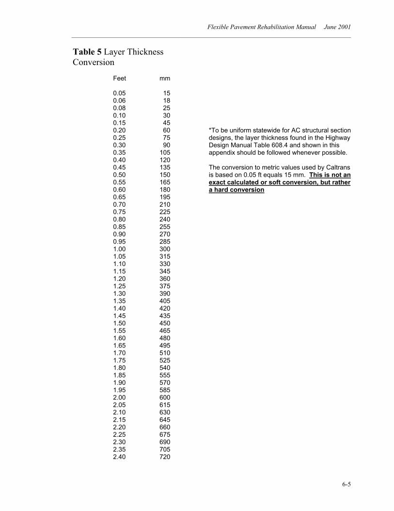
Flexible Pavement Rehabilitation Manual June 2001 ______________________________________________________________________________________
6-5
Table 5 Layer Thickness Conversion
Feet mm
0.05 15 0.06 18 0.08 25 0.10 30 0.15 45 0.20 60 0.25 75 0.30 90 0.35 105 0.40 120 0.45 135 0.50 150 0.55 165 0.60 180 0.65 195 0.70 210 0.75 225 0.80 240 0.85 255 0.90 270 0.95 285 1.00 300 1.05 315 1.10 330
1.15 345 1.20 360 1.25 375 1.30 390 1.35 405 1.40 420 1.45 435 1.50 450 1.55 465 1.60 480 1.65 495 1.70 510 1.75 525 1.80 540 1.85 555 1.90 570 1.95 585 2.00 600 2.05 615 2.10 630 2.15 645 2.20 660 2.25 675 2.30 690 2.35 705 2.40 720
*To be uniform statewide for AC structural section designs, the layer thickness found in the Highway Design Manual Table 608.4 and shown in this appendix should be followed whenever possible. The conversion to metric values used by Caltrans is based on 0.05 ft equals 15 mm. This is not an exact calculated or soft conversion, but rather a hard conversion

Flexible Pavement Rehabilitation Manual June 2001 ______________________________________________________________________________________
6-6
End of Manual