Embed Size (px)
Citation preview
Flexible Power Combinations, High-Speed and Versatile Load Simulations
The PEL-3000 Series, a single-channel, programmable D.C. electronic load with 0.01mA current resolution and 16A/ s current Slew Rate,μ
is very ideal for testing server power supply and SPS (Switching Power Supply) for commercial and industrial computers. For a heavy-duty
device like cloud ecosystem running 24-hour nonstop operations, a stable and high-power power supply, ranging from 350W to 1500W,
is required to maintain the normal operation of server, Hub, and the equipment of data storage and internet communications. Owing to
the increasing demand of data transmission and large scale data storage of telecommunications systems, the infrastructure of internet
communications is in the pace of rapid expansion. This has greatly boosted the market demand of telecommunications equipment
powered by power supply of 2000W and above. The flexible power combination of PEL-3000 Series meets the test requirements of present
high-power power supply. The PEL-3000H Series programmable DC Electronic load, which not only inherited functions and features
from the PEL-3000 Series but providing three current ranges for all PEL-3000H Series and adding voltage monitor BNC terminals on the
front panel. The PEL-3000H Series, a single-channel, programmable D.C. electronic load with 800V and 0.84A/ s current Slew Rate, isμ
ideal for the test of the high voltage devices such as the EV & HEV in-vehicle chargers, DC/DC converters or high-voltage batteries. With
respect to battery testing applications such as rechargeable battery for electrical tools, battery module and automobile battery, PEL-3000(H)
Series has three stand-alone models to offer including 175W, 350W, 1050W and Booster. By connecting Booster 2100W units with master
units, the maximum load capacity of the whole system can reach 9,450W. Hence, the PEL-3000(H) Series fulfills various power testing
requirements including medium to low power or high-power power supply.
The PEL-3000(H) Series has seven operating modes and three operating functions. Among the seven operating modes, four of them are
basic operating modes, including constant current, constant voltage, constant resistance, and constant power, and the other three are
advanced operating modes including constant current + constant voltage, constant resistance + constant voltage, and constant power +
constant voltage. Users must first select operating mode and then operating function based upon the test requirements. Static, Dynamic
and Sequence operating functions can be applied to different testing conditions including a fixed load level, switching between two levels
or switching among more than two levels. Sequence function is divided into Fast Sequence and Normal Sequence according to the test
time of each step. Both Dynamic and Sequence are to assist users to simulate the genuine load change. For instance, PEL-3000(H) Series
can simulate HEV current consumption to make sure that automobile battery can supply HEV with sufficient power need on the road. By
so doing, manufacturers can elevate product quality and reliability.
The Soft Start function of the PEL-3000(H) Series can set current rise time for the moment PEL-3000(H) Series is turned on to reduce the
abnormal situation of the voltage drop of power supply under test. The adjustable Under Voltage Protection (UVP), GO/NO GO voltage
input monitoring function, current monitoring function and Timer Function to control load activation time can be jointly applied to the
characteristic tests of battery bleeding to avoid battery damage during bleeding operation. Based upon the functionalities described above,
the PEL-3000(H) Series can test a vast variety of power supply ranging from the fundamental static sink current to complex dynamic load
simulations so as to enhance product quality and reliability.
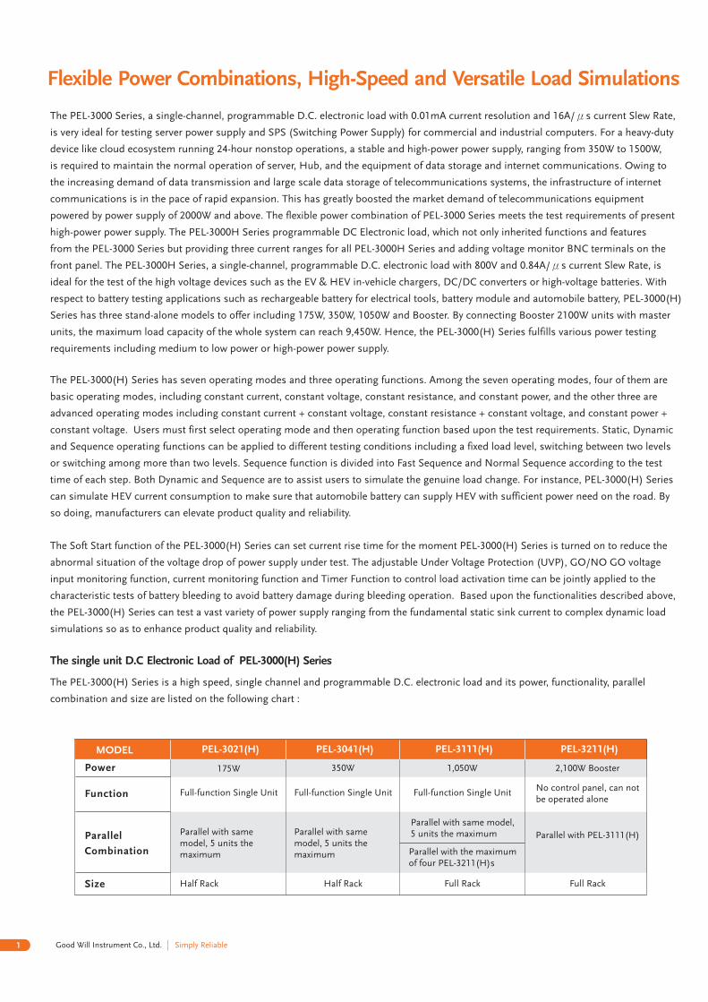
The PEL-3000(H) Series is a high speed, single channel and programmable D.C. electronic load and its power, functionality, parallel
combination and size are listed on the following chart :
MODEL PEL-3021(H) PEL-3041(H) PEL-3111(H) PEL-3211(H)
Power
Function
Parallel
Combination
Size
175W 350W 1,050W 2,100W Booster
Full-function Single Unit Full-function Single Unit Full-function Single UnitNo control panel, can notbe operated alone
Parallel with samemodel, 5 units themaximum
Parallel with samemodel, 5 units themaximum
Parallel with same model,5 units the maximum
Parallel with the maximumof four PEL-3211(H)s
Parallel with PEL-3111(H)
Half Rack Half Rack Full Rack Full Rack
1 Simply ReliableGood Will Instrument Co., Ltd.
A.
B.
CC Mode
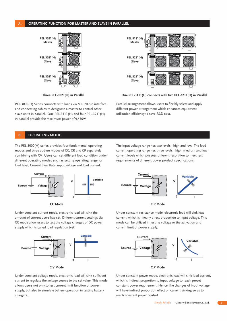
Three PEL-3021(H) in Parallel One PEL-3111(H) connects with two PEL-3211(H) in Parallel
OPERATING FUNCTION FOR MASTER AND SLAVE IN PARALLEL
PEL-3000(H) Series connects with loads via MIL 20-pin interface
and connecting cables to designate a master to control other
slave units in parallel. One PEL-3111(H) and four PEL-3211(H)
in parallel provide the maximum power of 9,450W.
Parallel arrangement allows users to flexibly select and apply
different power arrangement which enhances equipment
utilization efficiency to save R&D cost.
OPERATING MODE
The PEL-3000(H) series provides four fundamental operating
modes and three add-on modes of CC, CR and CP separately
combining with CV. Users can set different load condition under
different operating modes such as setting operating range for
load level, Current Slew Rate, input voltage and load current.
The input voltage range has two levels - high and low. The load
current operating range has three levels - high, medium and low
current levels which possess different resolution to meet test
requirements of different power product specifications.
Under constant current mode, electronic load will sink the
amount of current users has set. Different current settings via
CC mode allow users to test the voltage changes of DC power
supply which is called load regulation test.
C.R Mode
C.V Mode
Under constant resistance mode, electronic load will sink load
current, which is linearly direct proportion to input voltage. This
mode can be utilized in testing voltage or the activation and
current limit of power supply.
Under constant voltage mode, electronic load will sink sufficient
current to regulate the voltage source to the set value. This mode
allows users not only to test current limit function of power
supply, but also to simulate battery operation in testing battery
chargers.
C.P Mode
Under constant power mode, electronic load will sink load current,
which is indirect proportion to input voltage to reach preset
constant power requirement. Hence, the changes of input voltage
will have indirect proportion effect on current sinking so as to
reach constant power control.
PEL-3021(H)Master
PEL-3021(H)
Slave
PEL-3021(H)
Slave
PEL-3111(H)Master
PEL-3211(H)
Slave
PEL-3211(H)
Slave
2Good Will Instrument Co., Ltd.Simply Reliable
C.
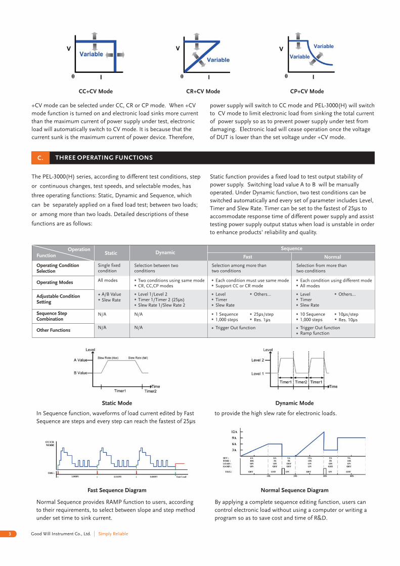
Static Mode Dynamic Mode
Fast Sequence Diagram Normal Sequence Diagram
+CV mode can be selected under CC, CR or CP mode. When +CV
mode function is turned on and electronic load sinks more current
than the maximum current of power supply under test, electronic
load will automatically switch to CV mode. It is because that the
current sunk is the maximum current of power device. Therefore,
power supply will switch to CC mode and PEL-3000(H) will switch
to CV mode to limit electronic load from sinking the total current
of power supply so as to prevent power supply under test from
damaging. Electronic load will cease operation once the voltage
of DUT is lower than the set voltage under +CV mode.
CC+CV Mode CR+CV Mode CP+CV Mode
THREE OPERATING FUNCTIONS
The PEL-3000 series, according to different test conditions, step(H)
or continuous changes, test speeds, and selectable modes, has
three operating functions: Static, Dynamic and Sequence, which
can be separately applied on a fixed load test; between two loads;
or among more than two loads. Detailed descriptions of these
functions are as follows:
Static function provides a fixed load to test output stability of
power supply. Switching load value A to B will be manually
operated. Under Dynamic function, two test conditions can be
switched automatically and every set of parameter includes Level,
Timer and Slew Rate. Timer can be set to the fastest of 25 s toμ
accommodate response time of different power supply and assist
testing power supply output status when load is unstable in order
to enhance products' reliability and quality.
In Sequence function, waveforms of load current edited by Fast
Sequence are steps and every step can reach the fastest of 25 sμ
to provide the high slew rate for electronic loads.
Normal Sequence provides RAMP function to users, according
to their requirements, to select between slope and step method
under set time to sink current.
By applying a complete sequence editing function, users can
control electronic load without using a computer or writing a
program so as to save cost and time of R&D.
OperationFunction
Operating ConditionSelection
Operating Modes
Adjustable ConditionSetting
Sequence StepCombination
Other Functions
Single fixedcondition
All modes
A/B ValueSlew Rate
N/A
N/A
Static DynamicSequence
Fast Normal
Selection from more thantwo conditions
Selection among more thantwo conditions
Selection between twoconditions
Each condition using different modeAll modes
Each condition must use same modeSupport CC or CR mode
Two conditions using same modeCR, CC,CP modes
LevelTimerSlew Rate
Others…
10 Sequence1,000 steps
10 s/stepμ
Trigger Out functionRamp function
LevelTimerSlew Rate
Others…
1 Sequence1,000 steps
25 s/stepμ
Res. 1 sμ
Trigger Out function
Level 1/Level 2Timer 1/Timer 2 (25 s)μ
Slew Rate 1/Slew Rate 2
N/A
N/A
3 Simply ReliableGood Will Instrument Co., Ltd.
Res. s10μ
ProtectionFunctions OCP OVP OPP OTP UVP RVP
Adjustable Thresholds
FixedN/ALoad Off
N/A N/AN/AN/ALimit Function
Fixed N/A
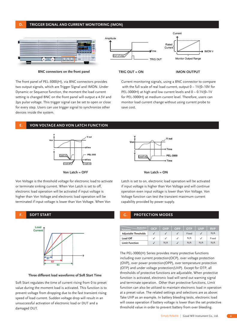
The front panel of PEL-3000(H), via BNC connectors provides
two output signals, which are Trigger Signal and IMON. Under
Dynamic or Sequence function, the moment the load current
setting is changed BNC on the front panel will output a 4.5V and
2 s pulse voltage. This trigger signal can be set to open or closeμ
for every step. Users can use trigger signal to synchronize other
devices inside the system.
BNC connectors on the front panel TRIG OUT = ON
Current monitoring signals, using a BNC connector to compare
with the full scale of real load current, output 0 ~ 1V(0~10V for
PEL-3000H) at high and low current levels and 0 ~ 0.1V(0~1V
for PEL-3000H) at medium current level. Therefore, users can
monitor load current change without using current probe to
save cost.
IMON OUTPUT
Von Voltage is the threshold voltage for electronic load to activate
or terminate sinking current. When Von Latch is set to off,
electronic load operation will be activated if input voltage is
higher than Von Voltage and electronic load operation will be
terminated if input voltage is lower than Von Voltage. When Von
Latch is set to on, electronic load operation will be activated
if input voltage is higher than Von Voltage and will continue
operation even input voltage is lower than Von Voltage. Von
Voltage function can test the transient maximum current
capability provided by power supply.
Von Latch = OFF Von Latch = ON
Soft Start regulates the time of current rising from 0 to preset
value during the moment load is activated. This function is to
prevent voltage from dropping due to the fast transient rising
speed of load current. Sudden voltage drop will result in an
unsuccessful activation of electronic load or DUT and a
damaged DUT.
Three different load waveforms of Soft Start Time
VON VOLTAGE AND VON LATCH FUNCTION
TRIGGER SIGNAL AND CURRENT MONITORING (IMON)
SOFT START
D.
F.
E.
4Good Will Instrument Co., Ltd.Simply Reliable
G. PROTECTION MODES
The PEL-3000(H) Series provides many protective functions
including over current protection(OCP), over voltage protection
(OVP), over power protection(OPP), over temperature protection
(OTP) and under voltage protection(UVP). Except for OTP, all
thresholds of protective functions are adjustable. When protective
function is activated, electronic load will send out warning signal
and terminate operation. Other than protective functions, Limit
function can also be utilized to maintain electronic load in operation
at a preset value. The related settings and selections are as above:
Take UVP as an example. In battery bleeding tests, electronic load
will cease operation if battery voltage is lower than the set protective
threshold value in order to prevent battery from over bleeding.
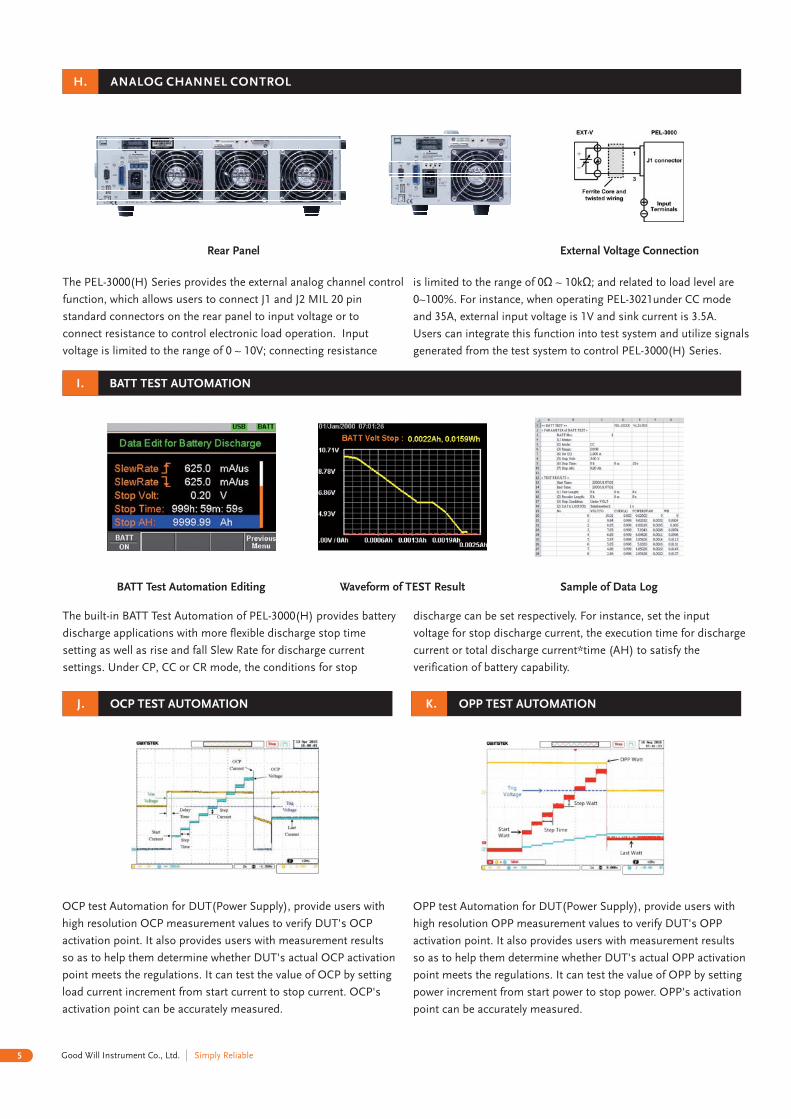
The PEL-3000(H) Series provides the external analog channel control
function, which allows users to connect J1 and J2 MIL 20 pin
standard connectors on the rear panel to input voltage or to
connect resistance to control electronic load operation. Input
voltage is limited to the range of 0 ~ 10V; connecting resistance
The built-in BATT Test Automation of PEL-3000(H) provides battery
discharge applications with more flexible discharge stop time
setting as well as rise and fall Slew Rate for discharge current
settings. Under CP, CC or CR mode, the conditions for stop
OCP test Automation for DUT(Power Supply), provide users with
high resolution OCP measurement values to verify DUT's OCP
activation point. It also provides users with measurement results
so as to help them determine whether DUT's actual OCP activation
point meets the regulations. It can test the value of OCP by setting
load current increment from start current to stop current. OCP's
activation point can be accurately measured.
is limited to the range of 0 ~ 10k ; and related to load level areΩ Ω
0~100%. For instance, when operating PEL-3021under CC mode
and 35A, external input voltage is 1V and sink current is 3.5A.
Users can integrate this function into test system and utilize signals
generated from the test system to control PEL-3000(H) Series.
OPP test Automation for DUT(Power Supply), provide users with
high resolution OPP measurement values to verify DUT's OPP
activation point. It also provides users with measurement results
so as to help them determine whether DUT's actual OPP activation
point meets the regulations. It can test the value of OPP by setting
power increment from start power to stop power. OPP's activation
point can be accurately measured.
BATT TEST AUTOMATION
OCP TEST AUTOMATION
BATT Test Automation Editing Waveform of TEST Result Sample of Data Log
External Voltage Connection
ANALOG CHANNEL CONTROLH.
I.
J. K.
5 Simply ReliableGood Will Instrument Co., Ltd.
discharge can be set respectively. For instance, set the input
voltage for stop discharge current, the execution time for discharge
current or total discharge current*time (AH) to satisfy the
verification of battery capability.
Rear Panel
OPP TEST AUTOMATION
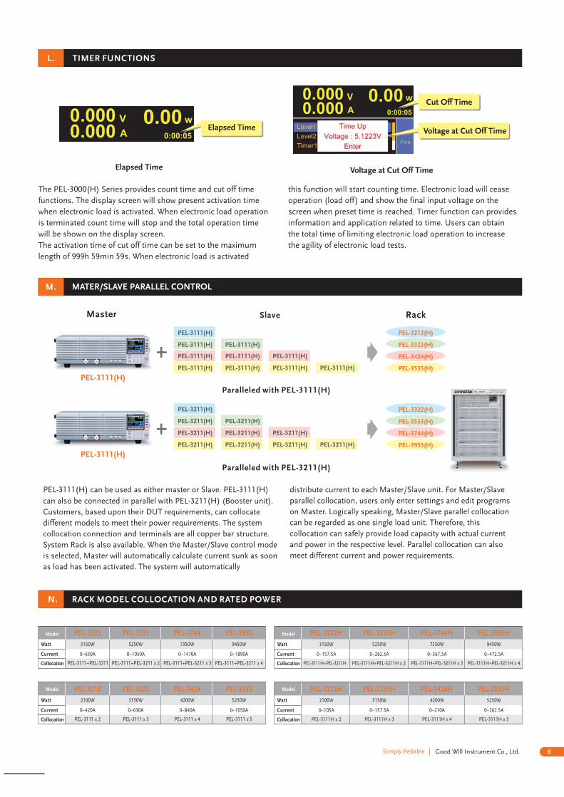
The PEL-3000(H) Series provides count time and cut off time
functions. The display screen will show present activation time
when electronic load is activated. When electronic load operation
is terminated count time will stop and the total operation time
will be shown on the display screen.
The activation time of cut off time can be set to the maximum
length of 999h 59min 59s. When electronic load is activated
this function will start counting time. Electronic load will cease
operation (load off) and show the final input voltage on the
screen when preset time is reached. Timer function can provides
information and application related to time. Users can obtain
the total time of limiting electronic load operation to increase
the agility of electronic load tests.
Elapsed Time Voltage at Cut Off Time
Elapsed Time
Cut Off Time
Voltage at Cut Off Time
TIMER FUNCTIONSL.
M.
N.
Model
Model
3150W
2100W
5250W
3150W
7350W
4200W
9450W
5250W
0~630A
0~420A
0~1050A
0~630A
0~1470A
0~840A
0~1890A
0~1050A
PEL-3111+PEL-3211
PEL-3111 x 2
PEL-3111+PEL-3211 x 2
PEL-3111 x 3
PEL-3111+PEL-3211 x 3
PEL-3111 x 4
PEL-3111+PEL-3211 x 4
PEL-3111 x 5
PEL-3322
PEL-3212
PEL-3533
PEL-3323
PEL-3744
PEL-3424
PEL-3955
PEL-3535
Watt
Watt
Current
Current
Collocation
Collocation
Model
Model
3150W
2100W
5250W
3150W
7350W
4200W
9450W
5250W
0~157 5A.
0~105A
0~262 5A.
0~157 5A.
0~367 5A.
0~210A
0~472 5A.
0~262 5A.
PEL-3111H+PEL-3211H
PEL-3111 x 2H
PEL-3111 +PEL-3211 x 2H H
PEL-3111 x 3H
PEL-3111 +PEL-3211 x 3H H
PEL-3111 x 4H
PEL-3111 +PEL-3211 x 4H H
PEL-3111 x 5H
PEL-3322H
PEL-3212H
PEL-3533H
PEL-3323H
PEL-3744H
PEL-3424H
PEL-3955H
PEL-3535H
Watt
Watt
Current
Current
Collocation
Collocation
MATER/SLAVE PARALLEL CONTROL
PEL-3111 can be used as either master or Slave. PEL-3111(H) (H)
can also be connected in parallel with PEL-3211 (Booster unit).(H)
Customers, based upon their DUT requirements, can collocate
different models to meet their power requirements. The system
collocation connection and terminals are all copper bar structure.
System Rack is also available. When the Master/Slave control mode
is selected, Master will automatically calculate current sunk as soon
as load has been activated. The system will automatically
distribute current to each Master/Slave unit. For Master/Slave
parallel collocation, users only enter settings and edit programs
on Master. Logically speaking, Master/Slave parallel collocation
can be regarded as one single load unit. Therefore, this
collocation can safely provide load capacity with actual current
and power in the respective level. Parallel collocation can also
meet different current and power requirements.
RACK MODEL COLLOCATION AND RATED POWER
Master
PEL-3111(H)
PEL-3211(H)
PEL-3111(H)
PEL-3211(H)
PEL-3111(H)
PEL-3211(H)
PEL-3111(H)
PEL-3211(H)
PEL-3111(H)
PEL-3211(H)
PEL-3111(H)
PEL-3211(H)
PEL-3111(H)
PEL-3211(H)
PEL-3111(H)
PEL-3211(H)
PEL-3111(H)
PEL-3211(H)
PEL-3111(H)
PEL-3211(H)
PEL-3212(H)
PEL-3322(H)
PEL-3323(H)
PEL-3533(H)
PEL-3424(H)
PEL-3744(H)
PEL-3535(H)
PEL-3955(H)
Slave
Paralleled with PEL-3111(H)
Paralleled with PEL-3211(H)
Rack
6Good Will Instrument Co., Ltd.Simply Reliable
PEL-3111(H)
PEL-3111(H)
Waveform of power load
P.
O.
Q.
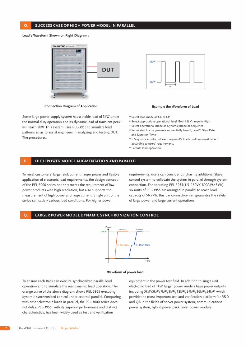
SUCCESS CASE OF HIGH POWER MODEL IN PARALLEL
Some large power supply system has a stable load of 3kW under
the normal duty operation and its dynamic load of transient peak
will reach 9kW. This system uses PEL-3955 to simulate load
patterns so as to assist engineers in analyzing and testing DUT.
The procedures:
HIGH POWER MODEL AUGMENTATION AND PARALLEL
To meet customers' larger sink current, larger power and flexible
application of electronic load requirements, the design concept
of the PEL-3000 series not only meets the requirement of low
power products with high resolution, but also supports the
measurement of high power and large current. Single unit of the
series can satisfy various load conditions. For higher power
requirements, users can consider purchasing additional Slave
control system to collocate the system in parallel through system
connection. For operating PEL-3955(1.5~150V/1890A/9.45kW),
six units of PEL-3955 are arranged in parallel to reach load
capacity of 56.7kW. Bus bar connection can guarantee the safety
of large power and large current operations.
LARGER POWER MODEL DYNAMIC SYNCHRONIZATION CONTROL
To ensure each Rack can execute synchronized parallel load
operation and to simulate the real dynamic load operation. The
orange curve of the above diagram shows PEL-3955 executing
dynamic synchronized control under external parallel. Comparing
with other electronic loads in parallel, the PEL-3000 series does
not delay. PEL-3955, with its superior performance and distinct
characteristics, has been widely used as test and verification
equipment in the power test field. In addition to single unit
electronic load of 1kW, larger power models have power outputs
including 3kW/5kW/7kW/9kW/18kW/27kW/36kW/54kW, which
provide the most important test and verification platform for R&D
and QA in the fields of server power system, communications
power system, hybrid power pack, solar power module.
Load's Waveform Shown on Right Diagram :
Connection Diagram of Application Example the Waveform of Load
DUT
* Select load mode as CC or CP
* Select appropriate operational level: Both I & V range in High
* Select operational mode as Dynamic mode or Sequence
* Set related load arguments sequentially Level1, Level2, Slew Rate
and Duration Time
* If Sequence is selected, each segment's load condition must be set
according to users' requirements
* Execute load operation
7 Simply ReliableGood Will Instrument Co., Ltd.
8Good Will Instrument Co., Ltd.Simply Reliable
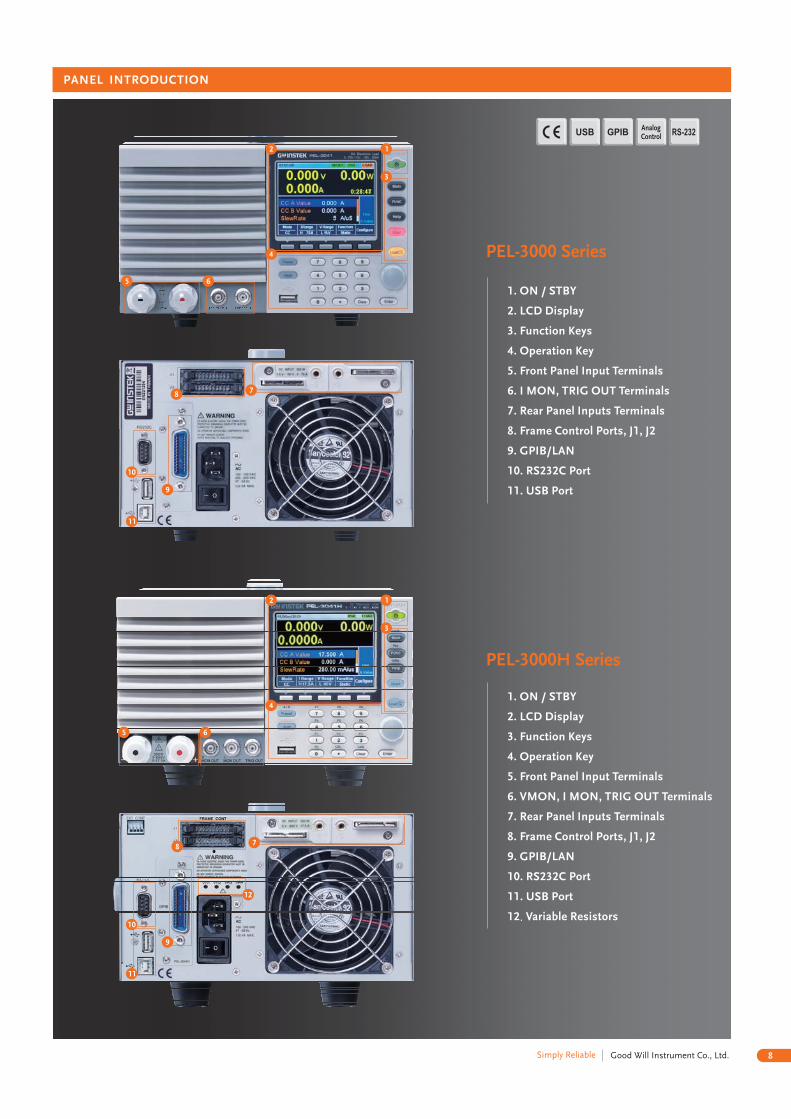
PANEL INTRODUCTION
1. ON / STBY
2. LCD Display
3. Function Keys
4. Operation Key
5. Front Panel Input Terminals
6. I MON, TRIG OUT Terminals
7. Rear Panel Inputs Terminals
8. Frame Control Ports, J1, J2
9. GPIB/LAN
10. RS232C Port
11. USB Port
1. ON / STBY
2. LCD Display
3. Function Keys
4. Operation Key
5. Front Panel Input Terminals
6. VMON, I MON, TRIG OUT Terminals
7. Rear Panel Inputs Terminals
8. Frame Control Ports, J1, J2
9. GPIB/LAN
10. RS232C Port
11. USB Port
.12 Variable Resistors
AnalogControl
9
9
10
10
11
11
8
8
7
7
4
5
2
3
6
1
12
PEL-3000 Series
4
5
2
3
6
1
PEL-3000H Series
9 Simply ReliableGood Will Instrument Co., Ltd.
Accuracy of Setting
CONSTANT POWER MODE
Operating Range
SLEW RATE
Capacity
Setting Range(CC mode)
Setting Range(CR Mode)
Range
Range
Range
H,M,L
H,M,L
HM
L
HM
L
H
M
L
10mW 1mW 0.1mW 10mW 1mW 0.1mW 100mW 10mW 1mW
±(0.6 % of set + 1.4 % of f.s ) + Vin /500k*5 *3 *2
Ω
17.5W~175W
1.75W~17.5W
0.175W~1.75W
35W~350W
3.5W~35W
0.35W~3.5W
105W~1050W 210W~2100W
10.5W~105W 21W~210W
1.05W~10.5W
2.5mA/ s~2.5A/ s� �
250 A/ s~250mA/ s� � �
25 A/ s~25mA/ s� � �
250 A/ s~250mA/ s� � �
25 A/ s~25mA/ s� � �
2.5 A/ s~2.5mA/ s� � �
5mA/ s~5A/ s� �
500 A/ s~500mA/ s� � �
50 A/ s~50mA/ s� � �
500 A/ s~500mA/ s� � �
50 A/ s~50mA/ s� � �
5 A/ s~5mA/ s� � �
16mA/ s~16A/ s� �
1.6mA/ s~1.6A/ s� �
160 A/ s~160mA/ s� � �
1.6mA/ s~1.6A/ s� �
160 A/ s~160mA/ s� � �
16 A/ s~16mA/ s� � �
ResolutionPARALLEL Mode
875W 1750W 5250W
±(10 % of set + 5 s)*9
�Accuracy of Setting
Resolution
Operation ModeT1 & T2Accuracy
Current Accuracy
Range
Range
H
H
M
M
L
L
CC , CR and CP0.025mS~10mS/Res : 1 s ; 1ms~60s/Res : 1ms�
2.5mA/ s~2.5A/ s� �
250 A/ s~250mA/ s� � �
250 A/ s~250mA/ s� � �
25 A/ s~25mA/ s� � �
25 A/ s~25mA/ s� � �
2.5 A/ s~2.5mA/ s� � �
5mA/ s~5A/ s� �
500 A/ s~500mA/ s� � �
500 A/ s~500mA/ s� � �
50 A/ s~50mA/ s� � �
50 A/ s~50mA/ s� � �
5 A/ s~5mA/ s� � �
16mA/ s~16A/ s� �
1.6mA/ s~1.6A/ s� �
1.6mA/ s~1.6A/ s� �
160 A/ s~160mA/ s� � �
160 A/ s~160mA/ s� � �
16 A/ s~16mA/ s� � �
±0.4%F.S. ±0.4%F.S. ±0.4%F.S. ±(1.2%of set+1.1% of F.S.)
N/A
N/A
N/A
N/A
DYNAMIC MODE
100ppm of setting
214.5(W)x124(H)x400(D)mm;Approx. 6kg
214.5(W)x124(H)x400(D)mm;Approx. 7kg
429.5(W)x128(H)x400(D)mm;Approx. 17kg
427.7(W)x128(H)x592.5(D)mm;Approx. 23kg
METER
VoltmeterAmmeterAmmeter(Parallel Operation) Accuracy ±(1.2% of rdg +1.1% of f.s.)
AccuracyAccuracy
±(0.1 % of rdg + 0.1 % of f.s)±(0.2 % of rdg + 0.3 % of f.s)
N/A
PEL-3111 with 4 boosterunits : Max 9.45kW
N/A
N/A
N/A
Model PEL-3021 PEL-3041 PEL-3111 PEL-3211VoltageCurrentPower
CONSTANT CURRENT MODEOperating Range
Resolution
Accuracy of Setting
Accuracy of Setting
Accuracy of Setting(Parallel)
Operating Range
Accuracy of Setting
Accuracy of Setting
CONSTANT VOLTAGE MODE
Operating Range
Accuracy of Setting
Range
Range
H
H,M
L
H,M,L
H,M,L
M
H
H,M
L
H,M,L
H,M,L
L
L
H,L
H,L
0~35A
1mA
400 S� 40 S� 4 S� 800 S� 80 S� 8 S� 2.4mS 240 S� 24 S�
0~3.5A
0.1mA
0~0.35A
0.01mA
0~70A
2mA
0~7A
0.2mA
0~0.7A
0.02mA
0~210A
10mA
0~21A
1mA
0~2.1A
0.1mA
±(0.2 % of set + 0.1 % of f.s ) + Vin /500 k*1 *2
Ω
±(0.2 % of set + 0.1 % of f.s ) + Vin /500 k*1 *2
Ω
±(1.2% of set +1.1% of f.s. )*3
23.3336S~400 S�
(42.857m ~2.5k )
2.33336S~40 S�(428.566m ~25k )
0.233336S~4 S�
(4.28566 250k )�
46.6672S~800 S�
(21.428m ~1.25k )
4.6667S~80 S�(214.28m ~12.5k )
0.46667S~8 S�
(2.1428 ~125k )
140.0016S~2.4mS(7.1427m ~416.6667 )
14.0001S~242.4 S�(71.427m ~4.16667k )
1.40001S~24.24 S�
(714.27m ~41.6667k )
±(0.5 % of set + 0.5 % of f.s ) + Vin /500k*6 *1 *3
Ω
±(0.5 % of set + 0.5 % of f.s ) + Vin /500k*6 *1 *3
Ω
1.5V~150V 1.5V~150V
1.5V~15V 1.5V~15V
10mV/1mV
±(0.1 % of set + 0.1 % of f.s)
0V~150V 0V~150V 0V~150V 0V~150V35A 70A 210A 420A175W500 kΩ 500 kΩ 500 kΩ 500 kΩ
350W 1050W 2100W
CR MODE
N/A
N/A
Resolution
Resolution
420A
±(1.2% of set+1.1% of f.s)
28.0032s~484.8 s�
280.0032s~4.8ms
(35.7135m ~2.083334 )Ω Ω
(3.5714m ~208.3334 )Ω Ω
±(1.2% of set +1.1% of f.s)
N/A
N/A
N/A
N/A
N/A
Parallel ±(1.2 % of set + 1.1 % of f.s )*3
Min. OperatingVoltage(DC)(Typ.)
[email protected] 0.75V@35A 0.75V@105A [email protected]@35A 1.5V@70A 1.5V@210A 1.5V@420A
Operation Mode CC, CR CC, CR CC, CR N/A
Slew Rate(CR Mode)
Slew Rate(CC Mode)
N/A
1mA 250mA~2.5A/ s)( �
100 A 25mA~250mA/ s)� �(10 A 2.5mA~25mA/ s)� �(1 A 250 A~2.5mA/ s)� � �(100nA 25 A~250 A/ s)( � � �
10nA 2.5 A~25 A/ s)( � � �
2mA 500mA~5A/ s)( �
200 A 50mA~500mA/ s)� �(20 A 5mA~25mA/ s)� �(2 A 500 A~5mA/ s)� � �(200nA 50 A~500 A/ s)( � � �
20nA 5 A~50 A/ s)( � � �
6mA 1.6A~16A/ s)( �
600 A 160mA~1.6A/ s)� �(60 A 16mA~160mA/ s)� �(6 A 1.6mA~16mA/ s)� �(600nA 160 A~1.6mA/ s)( � �
60nA 16 A~ A/ s)( � ���� �
PROTECTION FUNCTION
GENERAL
Interface
Input Range
Power(Max.)
90VAC~132VAC/180VAC~250VAC Single-phase; 47Hz~63Hz
90VA 110VA 190VA 230VAUSB/RS232/Analog Control (Standard) ; GPIB/LAN(Option)
Dimensions & Weight
Overvoltage protection(OVP), Overcurrent protection(OCP), Overpower protection(OPP), Overheat protection(OHP),Undervoltage protection(UVP), Reverse connection protection(REV)
Functions
±(1.2% of set+1.1% of f.s)
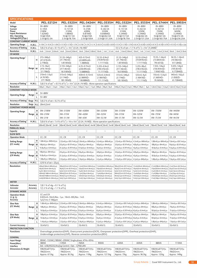
SPECIFICATIONS

10Good Will Instrument Co., Ltd.Simply Reliable
Operation ModeT1 & T2Accuracy
Slew Rate(CR Mode)
Slew Rate(CC Mode)
Current Accuracy
Range
Range
H
H
M
M
L
L
CC and CR0.025mS~10mS/Res : 1 s ; 1mS~30S/Res : 1mS�
3.2mA/ s~1.6A/ s� �
32mA/ s~16A/ s� �
320 A/ s~160mA/ s� � �
3.2mA/ s~1.6mA/ s� �
32 A/ s~16mA/ s� � �
320 A/ s~160mA/ s� � �
6.4mA/ s~1.6A/ s� �
64mA/ s~16A/ s� �
8mA/ s~1.6A/ s� �
80mA/ s~16A/ s� �
4.8mA/ s~1.6A/ s� �
48mA/ s~16A/ s� �
8mA/ s~1.6A/ s� �
80mA/ s~16A/ s� �
11.2mA/ s~1.6A/ s� �
112mA/ s~16A/ s� �
14.4mA/ s~1.6A/ s� �
144mA/ s~16A/ s� �
640 A/ s~160mA/ s� � �
6.4mA/ s~1.6A/ s� �
800 A/ s~160mA/ s� � �
8mA/ s~1.6A/ s� �
480 A/ s~160mA/ s� � �
4.8mA/ s~1.6A/ s� �
800 A/ s~160mA/ s� � �
8mA/ s~1.6A/ s� �
1.12mA/ s~160mA/ s� �
11.2mA/ s~1.6A/ s� �
1.44mA/ s~160mA/ s� �
14.4mA/ s~1.6A/ s� �
64 A/ s~16mA/ s� � �
640 A/ s~160mA/ s� � �
80 A/ s~16mA/ s� � �
800 A/ s~160mA/ s� � �
±0.4%F.S.
4.8mA/ s~1.6A/ s� �
48mA/ s~16A/ s� �
480 A/ s~160mA/ s� � �
4.8mA/ s~1.6A/ s� �
48 A/ s~16mA/ s� � �
480 A/ s~160mA/ s� � �
±0.4%F.S. ±0.4%F.S. ±0.4%F.S. ±0.4%F.S. ±0.4%F.S. ±0.4%F.S. ±0.4%F.S.
DYNAMIC MODE
1 S/1ms 100ppm� ±
VoltmeterAmmeter
AccuracyAccuracy
±(0.1 % of rdg + 0.1 % of f.s)±(0.2 % of rdg + 0.3 % of f.s)
PROTECTION FUNCTION
Model
VoltageCurrentPower
CONSTANT CURRENT MODE
Operating Range
Resolution
Accuracy of Setting
Operating Range
Accuracy of Setting
Accuracy of Setting
CONSTANT VOLTAGE MODE
Operating Range
Accuracy of Setting
CONSTANT POWER MODE
Operating Range
SLEW RATE
Capacity
Operation Mode
Setting Range(CC mode)
Setting Range(CR Mode)
Range
Range
Range
Range
Range
H
H,M,L
H,M,L
H,M,L
M
H
H,M,L
H,M,L
H,M,L
H,M,L
H,M,L
H
L
L
H,L
H,L
M
L
H
M
L
H
M
L
0~420A
20mA
4.8mS
200mW 20mW 2mW 300mW 30mW 3mW 400mW 500mW 300mW 500mW 700mW 900mW40mW 50mW 30mW 50mW 70mW 90mW4mW 5mW
480 S� 48 S� 7.2mS 720 S� 72 S� 9.6mS 12mS 7.2mS 12mS 16.8mS 21.6mS960 S� 1.2mS 720 S� 1.2mS 1.68mS 2.16mS96 S� 120 S�
0~42A
2mA
0~4.2A
0.2mA
0~630A
30mA
0~63A
3mA
0~6.3A
0.3mA
0~840A 0~1050A 0~630A 0~1050A 0~1470A 0~1890A
40mA 50mA 30mA 50mA 70mA 90mA
0~84A 0~105A 0~63A 0~105A 0~147A 0~189A
4mA 5mA 3mA 5mA 7mA 9mA
0~8.4A 0~10.5A N/A N/A N/A N/A
0.4mA 0.5mA N/A N/A N/A N/A
±(0.2 % of set + 0.1 % of f.s ) + Vin /(500/N k*1 *2
Ω)
280.0032S~4.8mS(3.57138m ~208.333 )
28.00032S~480 S(35.7138m ~2083.33 )
2.800032S~48 S(357.138m ~20.8333k )
420.0048S~7.2mS 560.0064S~9.6mS(1.78569m ~104.166 )
56.00064S~960 S(17.8569m ~1041.66 )
5.600064S~96 S(178.569m ~10.4166k )
700.008S~12mS(1.42855m ~83.3333 )
70.0008S~1.2mS(14.2855m ~833.333 )
7.00008S~120 S(142.855m ~8.33333k )
420.0048S~7.2mS(2.38092m ~138.888 )
42.00048S~720 S(23.8092m ~1388.88 )
700.008S~12mS(1.42855m ~83.3333 )
70.0008S~1.2mS(14.2855m ~833.333 )
980.0112S~16.8mS(1.02039m ~59.5238 )
98.00112S~1.68mS(10.2039m ~595.238 )
1260.0144S~21.6mS(793.641u ~46.2963 )
126.00144S~2.16mS(7.93641m ~462.963 )
(2.38092m ~138.888 )
42.00048S~720 S(23.8092m ~1388.88 )
4.200048S~72 S(238.092m ~13.8888k )
N/A
N/A
N/A
N/A
N/A
N/A
N/A
N/A
N/AN/AN/AN/A
N/A
N/A
N/A
N/A
N/A
N/A
N/A
N/A
N/A
N/A
N/A
N/A
±(0.5 % of set + 0.5 % of f.s ) + Vin /(500/N k*6 *3 *2
Ω)
±( + Vin x Vin /(500/N M0.6 % of set + 1.4 % of f.s )*3
Ω): alone operation specifications
1.5V~150V
1.5V~15V
10mV/1mV
±(0.1 % of set + 0.1 % of f.s)
210W~2100W
21W~210W
2.1W~21W
315W~3150W
31.5W~315W
3.15W~31.5W
420W~4200W 525W~5250W 315W~3150W 525W~5250W 735W~7350W 945W~9450W
42W~420W 52.5W~525W 31.5W~315W 52.5W~525W 93.5W~735W 94.5W~945W
4.2W~42W 5.25W~52.5W
32mA/ s~16A/ s� �
CC, CR CC, CR CC, CR CC, CR CC, CR CC, CR CC, CR CC, CR
3.2mA/ s~1.6A/ s� �
320 A/ s~160mA/ s� � �
3.2mA/ s~1.6A/ s� �
320 A/ s~160mA/ s� � �
32 A/ s~16mA/ s� � �
64mA/ s~16A/ s� � 80mA/ s~16A/ s� � 48mA/ s~16A/ s� � 80mA/ s~16A/ s� � 112mA/ s~16A/ s� � 144mA/ s~16A/ s� �
6.4mA/ s~1.6A/ s� � 8mA/ s~1.6A/ s� � 4.8mA/ s~1.6A/ s� � 8mA/ s~1.6A/ s� � 11.2mA/ s~1.6A/ s� � 14.4mA/ s~1.6A/ s� �
640 A/ s~160mA/ s� � � 800 A/ s~160mA/ s� � �
6.4mA/ s~1.6A/ s� � 8mA/ s~1.6A/ s� � 4.8mA/ s~1.6A/ s� � 8mA/ s~1.6A/ s� � 11.2mA/ s~1.6A/ s� � 14.4mA/ s~1.6A/ s� �
640 A/ s~160mA/ s� � � 800 A/ s~160mA/ s� � � 480 A/ s~160mA/ s� � � 800 A/ s~160mA/ s� � � 1.12mA/ s~160mA/ s� � 1.44mA/ s~160mA/ s� �
64 A/ s~16mA/ s� � � 80 A/ s~16mA/ s� � �
CR MODE
Resolution
Resolution
Resolution
PARALLEL Mode
±(10 % of set + 5 s)*9
�
48mA/ s~16A/ s� �
4.8mA/ s~1.6A/ s� �
480 A/ s~160mA/ s� � �
4.8mA/ s~1.6A/ s� �
480 A/ s~160mA/ s� � �
48 A/ s~16mA/ s� � �
Accuracy of Setting
METER
598(W)x877(H)x706(D)mm;
Approx. 67.5kg
598(W)x877(H)x706(D)mm;
Approx. 85.5kg
598(W)x877(H)x706(D)mm;
Approx. 110kg
598(W)x877(H)x706(D)mm;
Approx. 127.5kg
598(W)x877(H)x706(D)mm;
Approx. 73kg
598(W)x877(H)x706(D)mm;
Approx. 96.5kg
598(W)x877(H)x706(D)mm;
Approx. 125kg
598(W)x877(H)x706(D)mm;
Approx. 149kg
GENERAL
Interface
Input Range
Power(Max.)
90VAC~132VAC/180VAC~250VAC Single-phase; 47Hz~63Hz380VA 570VA 760VA 950VA 420VA 650VA 880VA 1110VAUSB/RS232/Analog Control (Standard) ; GPIB/LAN(Option)
Dimensions & Weight
Min. OperatingVoltage(DC)(Typ.)
PEL-3212 PEL-3323 PEL-3424 PEL-3535 PEL-3322 PEL-3533 PEL-3744 PEL-39550V~150V 0V~150V 0V~150V 0V~150V 0V~150V 0V~150V 0V~150V 0V~150V0~420A 0~630A 0~840A 0~1050A 0~630A 0~1050A 0~1470A 0~1890A2100W 3150W 4200W 5250W 3150W 5250W 7350W 9450W
0.75V@210A 0.75V@315A 0.75V@420A 0.75V@525A 0.75V@315A 0.75V@525A 0.75V@735A [email protected]@420A 1.5V@630A 1.5V@840A 1.5V@1050A 1.5V@630A 1.5V@1050A 1.5V@1470A 1.5V@1890A
250 kΩ 166.7 kΩ 125 kΩ 100 kΩ 500 kΩ 500 kΩ 500 kΩ 500 kΩ
Overvoltage protection(OVP), Overcurrent protection(OCP), Overpower protection(OPP), Overheat protection(OHP),Undervoltage protection(UVP), Reverse connection protection(REV)
Functions
Resolution 12mA(1.6A~16A/ s)�
1.2mA(160mA~1.6A/ s)�
120 A(16mA~160mA/ s)� �
1 A(1.6mA~16mA/ s)�� �
1.2 A(160 A~1.6mA/ s)� � �
120nA(16 A~160 A/ s)� � �
30mA(1.6A~16A/ s)�
3mA(160mA~1.6A/ s)�
300 A(16mA~160mA/ s)� �
A(1.6mA~16mA/ s)��� �
3 A(160 A~1.6mA/ s)� � �
300nA(16 A~160 A/ s)� � �
18mA(1.6A~16A/ s)�
1.8mA(160mA~1.6A/ s)�
180 A(16mA~160mA/ s)� �
18 A(1.6mA~16mA/ s)� �
1.800 A(160 A~1.6mA/ s)� � �
180nA(16 A~160 A/ s)� � �
18mA(1.6A~16A/ s)�
1.8mA(160mA~1.6A/ s)�
180 A(16mA~160mA/ s)� �
18 A(1.6mA~16mA/ s)� �
1.8 A(160 A~1.6mA/ s)� � �
N/A
42mA(1.6A~16A/ s)�
4.2mA(160mA~1.6A/ s)�
420 A(16mA~160mA/ s)� �
42 A(1.6mA~16mA/ s)� �
4.2 A(160 A~1.6mA/ s)� � �
N/A
24mA/ s(1.6A~16A/ s)� �
2.4mA/ s(160mA~1.6A/ s)� �
240 A/ s(16mA~160mA/ s)� � �
24 A/ s(1.6mA~16mA/ s)� � �
2.4 A/ s(160 A~1.6mA/ s)� � � �
240nA/ s(16 A~ A/ s)� � ���� �
30mA(1.6A~16A/ s)�
3mA(160mA~1.6A/ s)�
300 A(16mA~160mA/ s)� �
30 A(1.6 A~16mA/ s)� � �
3 A(160 A~1.6mA/ s)� � �
N/A
54mA(1.6A~16A/ s)�
5.4mA(160mA~1.6A/ s)�
540 A(16mA~160mA/ s)� �
54 A(1.6mA~16mA/ s)� �
5.4 A(160 A~1.6mA/ s)� � �
N/A
SPECIFICATIONS
11 Simply ReliableGood Will Instrument Co., Ltd.
Accuracy of Setting
Operating Range
SLEW RATE
Capacity
Setting Range(CC mode)
Setting Range(CR Mode)
Range
Range
Range
H,M
H,M,L
HML
H
M
L
H
M
L
10mW 1mW 0.1mW 10mW 1mW 0.1mW 100mW 10mW 1mW
±(0.6 % of set + 1.4 % of f.s)+Vin/3.24MΩ
17.5W~175W1.75W~17.5W0.175W~1.75W
35W~350W3.5W~35W0.35W~3.5W
105W~1050W 210W~2100W10.5W~105W 21W~210W1.05W~10.5W 2.1W~21W
0.14mA/ s~140mA/ s� �
0.014 A/ s~14mA/ s� � �
1.4 A/ s~1400 A/ s� � � �
0.014mA/ s~14mA/ s� �
0.0014mA/ s~1.4mA/ s� �
0.14 A/ s~140 A/ s� � � �
0.280mA/ s~280.0mA/ s� �
0.0280mA/ s~28.00mA/ s� �
2.80 A/ s~2800 A/ s� � � �
0.0280mA/ s~28.00mA/ s� �
0.00280mA/ s~2.800mA/ s� �
0.280 A/ s~280.0 A/ s� � � �
0.840mA/ s~840mA/ s� �
0.0840mA/ s~84.00mA/ s� �
0.00840mA/ s~8.400mA/ s� �
0.0840mA/ s~84.00mA/ s� �
0.00840mA/ s~8.400mA/ s� �
0.000840mA/ s~0.8400mA/ s� �
ResolutionPARALLEL Mode
875W 1750W 5250W
±(10 % of set + 25 s)�Accuracy of Setting
Resolution
Operation ModeT1 & T2Accuracy
Current Accuracy
Range
Range
H
H
M
M
L
L
CC, CR, CP0.025mS~10mS/Res : 1 s ; 10ms~30s/Res : 1ms�
0.140mA/ s~140.0mA/ s� �
0.014mA/ s~14.000mA/ s� �
0.014mA/ s~14.00mA/ s� �
0.0014mA/ s~1.4000mA/ s� �
1.400 A/ s~1400.0 A/ s� � � �
0.1400 A/ s~140.00 A/ s� � � �
0.280mA/ s~280.0mA/ s� �
0.028mA/ s~28.00mA/ s� �
0.028mA/ s~28.00mA/ s� �
2.8 A/ s~2.800mA/ s� � �
2.800 A/ s~2800 A/ s� � � �
0.280 A/ s~280.0 A/ s� � � �
0.840mA/ s~840.0mA/ s� �
0.084mA/ s~84.00mA/ s� �
0.084mA/ s~84.00mA/ s� �
0.0084mA/ s~8.400mA/ s� �
0.0084mA/ s~8.400mA/ s� �
0.00084mA/ s~0.8400mA/ s� �
±0.4%F.S. ±0.4%F.S. ±0.4%F.S. ±0.4%F.S.
N/A
N/A
N/A
DYNAMIC MODE
± 100ppm of setting ± 100ppm of setting
213.8(W)x124(H)x400.5(D)mm;Approx. 6kg
213.8(W)x124(H)x400.5(D)mm;Approx. 7kg
427.8(W)x124(H)x400.5(D)mm;Approx. 17kg
427.7(W)x127.8(H)x553.5(D)mm;Approx. 23kg
METER
VoltmeterAmmeterAmmeter(Parallel Operation) Accuracy ±(1.2% of rdg +1.1% of f.s.) ±(1.2% of rdg +1.1% of f.s.)TYP
AccuracyAccuracy
±(0.1 % of rdg + 0.1 % of f.s) ±(0.1 % of rdg + 0.1 % of f.s)TYP±(0.2 % of rdg + 0.3 % of f.s)
N/A
PEL-3111H with 4 boosterunits : Max 9.45kW
N/A
N/A
N/A
Model PEL-3021H PEL-3041H PEL-3111H PEL-3211HVoltageCurrentPower
CONSTANT CURRENT MODEOperating Range
Resolution
Accuracy of Setting
Accuracy of Setting
Accuracy of Setting(Parallel)
Operating Range
Accuracy of Setting
Accuracy of Setting
CONSTANT VOLTAGE MODE
Operating Range
Accuracy of Setting
Range
Range
Range
Parallel
Range
H
H,M
L
H,M,L
H,M,L
M
H
H,M
L
H,M,L
L
L
H,L
H,L
0~8 75A.
300 A�
30 S� 3�S 0.3 S� 60 S� 6�S 0.6 S� 180 S� 18 S� 1.8 S�
0~875mA
30 A�
0~87 5mA.
3�A
0~17 5A.
0.6mA
0~1 75A.
60 A�
0~175mA
6�A
0~52.5A 0~105A
2mA
0~5.25A 0~10.5A
200 A�
0~525mA 0~1.05A
20 A�
±(0.2 % of set + 0.1 % of f.s ) + Vin /3.24M*1 *2
Ω
±(0.2 % of set + 0.1 % of f.s ) + Vin /3.24M*1 *2
Ω
±(1.2% of set +1.1% of f.s. )*3
1.75S~30 S�
(571m ~33.3k )
175mS~3 S�(5.71 ~333k )
17.5mS~0.3 S�
(57.1 3.33M )�
3.5S~60 S�
(285m ~16.6k )
350mS~6 S�(2.85 ~166k )
35mS~0.6 S�
(28.5 ~1.66M )
10.5S~180 S�
(95.2m ~5.55k )
1.05S~18 S�(952m ~55.5k )
105mS~1.8 S�
(9.52 ~555k )
±(0.5% set + 0.5% f.S ) + Vin /3.24M*1 *2
Ω
±(0.5% set + 0.5% f.S ) + Vin /3.24M*1 *2
Ω
5V~800V 5V~800V
5V~80V 5V~80V
20mV/2mV
±(0.2% of set + 0.2% of f.s) ±(0.2% of set + 0.2% of f.s)
±(0.2% of set + 0.2% of f.s) ±(0.2% of set + 0.2% of f.s)
0V~800V 0V~800V 0V~800V 0V~800V8 75A. 17 5A. 52 5A. 105A175W3 24M. Ω 3 24. MΩ 3 24. MΩ 3 24. MΩ
350W 1050W 2100W
21S~360 S�
(47.6m ~2.777k )
2.1S~36 S�(476m ~27.77k )
210mS~3.6 S�
(4.762 ~277.7k )
CR MODE
N/A
N/A
N/A
Resolution
Resolution
±(1.2% of set+1.1% of f.s)
±(1.2% of set +1.1% of f.s)TYP
N/A
N/A
N/A
N/A
SPECIFICATIONS
Parallel ±(1.2 % of set + 1.1 % of f.s )*3
Min. OperatingVoltage(DC)(Typ.)
5V@8 75A. 5V@17 5A. 5V@52 5A. [email protected]@4 375A. 2.5V@8 75A. 2.5V@26 25A. 2.5V@52 5A.
Operation Mode CC, CR CC, CR CC, CR N/A
Slew Rate(CR Mode)
Slew Rate(CC Mode)
N/A
50 A 14mA~140mA/ s)� �(5 A 1.4mA~14mA/ s)� �(0.5 A 140 A~1.4mA/ s)� � �(50nA 14 A~140 A/ s)( � � �
5nA 1.4 A~14 A/ s)( � � �
0.5nA 0.14 A~1.4 A/ s)( � � �
100 A 28mA~280mA/ s)� �(10 A 2.8mA~28mA/ s)� �(1 A 280 A~2.8mA/ s)� � �(0.1 A 28 A~280 A/ s)� � � �(10nA 2.8 A~28 A/ s)( � � �
1nA 0.28 A~2.8 A/ s)( � � �
300 A 84mA~0.84A/ s)� �(30 A 8.4mA~84mA/ s)� �(3 A 840 A~8.4mA/ s)� � �(0.3 A 84 A~840 A/ s)� � � �(30nA 8.4 A~84 A/ s)( � � �
3nA 0.84 A~ A/ s)( � �� �
PROTECTION FUNCTION
GENERAL
Interface
Input Range
Power(Max.)
90VAC~132VAC/180VAC~250VAC Single-phase; 47Hz~63Hz
90VA 110VA 190VA 230VAStd : USB/RS232/Analog Control ; Opt : GPIB/LAN
Dimensions & Weight
Overvoltage protection(OVP), Overcurrent protection(OCP), Overpower protection(OPP), Overheat protection(OHP),Undervoltage protection(UVP), Reverse connection protection(REV)
Functions
CONSTANT POWER MODE
TYP
H,M,L
±(5 % of f.s)TYP
N/AN/A
12Good Will Instrument Co., Ltd.Simply Reliable
Operation ModeT1 & T2Accuracy
Slew Rate(CR Mode)
Slew Rate(CC Mode)
Current Accuracy
Range
Range
H
H
M
M
L
L
CC and CR0.025mS~10mS/Res : 1 s ; 10mS~30S/Res : 1mS�
168 A/ s~8.4mA/ s� � �
1.68mA/ s~840mA/ s� �
16.8 A/ s~8.4mA/ s� � �
168 A/ s~84mA/ s� � �
1. A/ s~840 A/ s�� � � �
16.8 A/ s~8.4mA/ s� � �
±0.4%F.S.
252 A/ s~83.97mA/ s� � � 336 A/ s~84mA/ s� � � 420 A/ s~84mA/ s� � � 252 A/ s~83.97mA/ s� � � 420 A/ s~84mA/ s� � � 588 A/ s~84mA/ s� � � 756 A/ s~83.97mA/ s� � �
2.52mA/ s~839.7mA/ s� � 3.36mA/ s~840mA/ s� � 4.2mA/ s~840mA/ s� � 2.52mA/ s~839.7mA/ s� � 4.2mA/ s~840mA/ s� � 5.88mA/ s~840mA/ s� � 7.56mA/ s~839.7mA/ s� �
25.2 A/ s~8.397mA/ s� � � 33.6 A/ s~8.4mA/ s� � � 42 A/ s~8.4mA/ s� � � 25.2 A/ s~8.397mA/ s� � � 42 A/ s~8.4mA/ s� � � 58.8 A/ s~8.4mA/ s� � � 75.6 A/ s~8.397mA/ s� � �
252 A/ s~83.97mA/ s� � � 336 A/ s~84mA/ s� � � 420 A/ s~84mA/ s� � � 252 A/ s~83.97mA/ s� � � 420 A/ s~84mA/ s� � � 588 A/ s~84mA/ s� � � 756 A/ s~83.97mA/ s� � �
2.52 A/ s~839.7 A/ s� � � � 3.36 A/ s~840 A/ s� � � � 4.2 A/ s~840 A/ s� � � � 2.52 A/ s~839.7 A/ s� � � � 4.2 A/ s~840 A/ s� � � � 5.88 A/ s~840 A/ s� � � � 7.56 A/ s~839.7 A/ s� � � �
25.2 A/ s~8.397mA/ s� � � 33.6 A/ s~8.4mA/ s� � � 42 A/ s~8.4mA/ s� � � 25.2 A/ s~8.397mA/ s� � � 42 A/ s~8.4mA/ s� � � 58.8 A/ s~8.4mA/ s� � � 75.6 A/ s~8.397mA/ s� � �
±0.4%F.S. ±0.4%F.S. ±0.4%F.S. ±0.4%F.S. ±0.4%F.S. ±0.4%F.S. ±0.4%F.S.
DYNAMIC MODE
1 S/1ms 100ppm� ±
VoltmeterAmmeter
AccuracyAccuracy
±(0.1 % of rdg + 0.1 % of f.s)±(1.2 % of rdg + 1.1 % of f.s)
PROTECTION FUNCTION
Model
VoltageCurrentPower
CONSTANT CURRENT MODE
Operating Range
Resolution
Accuracy of Setting
Operating Range*4
Accuracy of Setting*5
Accuracy of Setting*8
CONSTANT VOLTAGE MODE
Operating Range
Accuracy of Setting*7
CONSTANT POWER MODE
Operating Range
SLEW RATE
Capacity
Operation Mode
Setting Range(CC mode)
Setting Range(CR Mode)
Range
Range
Range
Range
Range
H
H,M,L
H,M,L
H,M,L
M
H
H,M,L
H,M,L
H,M,L
H
L
L
H,L
H,L
M
L
H
M
L
H
M
L
0~105A
4mA
360 S�
200mW 20mW 2mW 300mW 30mW 3mW 400mW 500mW 300mW 500mW 700mW 900mW40mW 50mW 30mW 3mW 5mW 7mW 9mW50mW 70mW 90mW4mW 5mW
36 S� 3.6 S� 540 S� 54 S� 5.4 S� 720 S� 900 S� 540 S� 5.4 S� 900 S� 9 S� 1.26mS 12.6 S� 1.62mS 16.2 S�72 S� 90 S� 54 S� 90 S� 126 S� 162 S�7.2 S� 9 S�
0~10.5A
0.4mA
0~1.05A
0.04mA
0~157.5A
6mA
0~15.75A
0.6mA
0~1.575A
0.06mA
0~210A 0~262.5A 0~157.5A 0~262.5A 0~367.5A 0~472.5A0~3.675A0~2.625A0~1.575A 0~4.725A
8mA 10mA 6mA 10mA 14mA 18mA
0~21A 0~26.25A 0~15.75A 0~26.25A 0~36.75A 0~47.25A
0.8mA 1mA 0.6mA 0.06mA 0.1mA 0.14mA 0.18mA1mA 1.4mA 1.8mA
0~2.1A 0~2.625A
0.08mA 0.1mA
±(0.2 % of set + 0.1 % of f.s ) + Vin /(3.24 / N) M*1 *2 *3
Ω ±(1.2 % of set + 1.1 % of f.s ) + Vin /3.24M*1 *2 *3
Ω
21S~360 S�
(47.619m ~Ω
2.778k )Ω
2.1S~36 S�
(476.19m ~Ω
27.778k )Ω
210mS~3.6 S�
(4.7619 ~Ω
277.78k )Ω
31.5S~540 S� 42S~0.72mS(23.8095m ~Ω
1.3889k )Ω
4.2S~0.72mS(238.095m ~Ω
13.8889k )Ω
420mS~0.72mS(2.38095 ~Ω
138.888k )Ω
52.5S~0.9mS 31.5S~540 S� 52.5S~0.9mS 73.5S~1.26mS 94.5S~1.26mS(19.0476m ~Ω (31.746m ~Ω (19.0476m ~Ω (13.6054m ~Ω (10.582m ~Ω
1.11111k )Ω 1.85185k )Ω 1.11111k )Ω 793.651 )Ω 617.284 )Ω
5.25S~0.9mS(190.476m ~Ω
11.1111k )Ω
3.15S~540 S�
(317.46m ~Ω
18.5185k )Ω
5.25S~90 S�
(190.476m ~Ω
11.1111k )Ω
7.35S~126 S�
(136.054m ~Ω
7.93651k )Ω
9.45S~126 S�
(105.82m ~Ω
6.17284k )Ω
525mS~0.9mS(1.90476 ~Ω
111.111k )Ω
315mS~540 S�
(3.1746 ~Ω
185.185k )Ω
525mS~9 S�
(1.90476 ~Ω
111.111k )Ω
735mS~12.6 S�
(1.36054 ~Ω
79.365k )Ω
945mS~162 S�
(1.0582 ~Ω
61.7284k )Ω
(31.746m ~Ω
1.85185k )Ω
3.15S~540 S�
(317.46m ~Ω
18.5185k )Ω
315mS~540 S�
(3.1746 ~Ω
185.185k )Ω
±(0.5 % of set + 0.5 % of f.s ) + Vin /(3.24 / N M*6 *1 *2
Ω) : Alone operation specifications
±(0.6 % of set + 1.4 % of f.s ) + Vin x Vin /(3.24 / N M*3 *3
Ω) : Alone operation specifications
5V~800V
5V~80V
20mV/2mV
±(0.2 % of set + 0.2 % of f.s)
0W~2100W
0W~210W
0W~21W
0W~3150W
0W~315W
0W~31.5W
0W~4200W 0W~5250W 0W~3150W 0W~5250W 0W~7350W 0W~9450W
0W~420W 0W~525W 0W~315W
0W~31.5W
0W~525W
0W~52.5W
0W~735W
0W~73.5W
0W~945W
0W~94.5W0W~42W 0W~52.5W
1.68mA/ s~840mA/ s� �
168 A/ s~84mA/ s� � �
16.8 A/ s~8.4mA/ s� � �
168 A/ s~84mA/ s� � �
16.8 A/ s~8.4mA/ s� � �
1.68 A/ s~840 A/ s� � � �
2.52mA/ s~839.7mA/ s� �
252 A/ s~83.97mA/ s� � �
25.2 A/ s~8.397mA/ s� � �
252 A/ s~83.97mA/ s� � �
25.2 A/ s~8.397mA/ s� � �
2.52 A/ s~839.7 A/ s� � � �
3.36mA/ s~840mA/ s� �
336 A/ s~84mA/ s� � �
33.6 A/ s~8.4mA/ s� � �
336 A/ s~84mA/ s� � �
33.6 A/ s~8.4mA/ s� � �
3.36 A/ s~840 A/ s� � � �
4.2mA/ s~840mA/ s� � 2.52mA/ s~839.70mA/ s� � 4.2mA/ s~840mA/ s� � 5.88mA/ s~840mA/ s� � 7.56mA/ s~839.7mA/ s� �
420 A/ s~84mA/ s� � � 252 A/ s~83.97mA/ s� � � 420 A/ s~84mA/ s� � � 588 A/ s~84mA/ s� � � 756 A/ s~83.97mA/ s� � �
42 A/ s~8.4mA/ s� � � 25.2 A/ s~8.397mA/ s� � � 42 A/ s~8.4mA/ s� � � 58.8 A/ s~8.4mA/ s� � � 75.6 A/ s~8.397mA/ s� � �
420 A/ s~84mA/ s� � � 252 A/ s~83.97mA/ s� � � 420 A/ s~84mA/ s� � � 588 A/ s~84mA/ s� � � 756 A/ s~83.97mA/ s� � �
42 A/ s~8.4mA/ s� � � 25.2 A/ s~8.397mA/ s� � � 42 A/ s~8.4mA/ s� � � 58.8 A/ s~8.4mA/ s� � � 75.6 A/ s~8.397mA/ s� � �
4.2 A/ s~840 A/ s� � � � 2.52 A/ s~839.7 A/ s� � � � 4.2 A/ s~840 A/ s� � � � 5.88 A/ s~840 A/ s� � � � 7.56 A/ s~839.7 A/ s� � � �
CC, CR CC, CR CC, CR CC, CR CC, CR CC, CR CC, CR CC, CR
CR MODE
Resolution
Resolution
Resolution
PARALLEL Mode
±(10 % of set + 25 s)�Accuracy of Setting*9
METER
598(W)x877(H)x706(D)mm;
Approx. 67.5kg
598(W)x877(H)x706(D)mm;
Approx. 85.5kg
598(W)x877(H)x706(D)mm;
Approx. 110kg
598(W)x877(H)x706(D)mm;
Approx. 127.5kg
598(W)x877(H)x706(D)mm;
Approx. 73kg
598(W)x877(H)x706(D)mm;
Approx. 96.5kg
598(W)x877(H)x706(D)mm;
Approx. 125kg
598(W)x877(H)x706(D)mm;
Approx. 149kg
GENERAL
Interface
Input Range
Power(Max.)
90VAC~132VAC/180VAC~250VAC Single-phase; 47Hz~63Hz380VA 570VA 760VA 950VA 420VA 650VA 880VA 1110VAStd : USB/RS232/Analog Control ; Opt. : GPIB/LAN
Dimensions & Weight
SPECIFICATIONS
Min. OperatingVoltage(DC)(Typ.)
PEL-3212H PEL-3323H PEL-3424H PEL-3535H PEL-3322H PEL-3533H PEL-3744H PEL-3955H0V~800V 0V~800V 0V~800V 0V~800V 0V~800V 0V~800V 0V~800V 0V~800V0~105A 0~157.5A 0~210A 0~262.5A 0~157.5A 0~262.5A 0~367.5A 0~472.5A2100W 3150W 4200W 5250W 3150W 5250W 7350W 9450W
5V@105A [email protected] 5V@210A [email protected] [email protected] [email protected] [email protected] [email protected]@52.5A [email protected] 2.5V@105A [email protected] [email protected] [email protected] [email protected] [email protected]
1.62MΩ 1.08MΩ 0.81MΩ 0.648MΩ 3.24MΩ 3.24MΩ 3.24MΩ 3.24MΩ
Overvoltage protection(OVP), Overcurrent protection(OCP), Overpower protection(OPP), Overheat protection(OHP),Undervoltage protection(UVP), Reverse connection protection(REV)
Functions
Resolution 600 A(168mA~840mA/ s)� �
60 A(16.8mA~84mA/ s)� �
6 A(1.68mA~8.4mA/ s)� �
600nA(0.1680mA~84mA/ s)�
60nA(0.01680mA~8.4mA/ s)�
6nA(0.00168mA~0.84mA/ s)�
900 A(252mA~839.7mA/ s)� �
90 A(25.2mA~83.97mA/ s)� �
9 A(2.52mA~8.397mA/ s)� �
900nA(252nA~83.97mA/ s)�
90nA(25.2 A~8.397 A/ s)� � �
9nA(2.52 A~0.8397 A/ s)� � �
1.2mA(336mA~840mA/ s)�
120 A(33.6mA~84mA/ s)� �
12 A(3.36mA~8.4mA/ s)� �
1.2 A(336 A~84mA/ s)� � �
120nA(33.6 A~8.4mA/ s)� �
12nA(3.36 A~0.84mA/ s)� �
1.5mA(420mA~840mA/ s)�
150 A(42mA~84mA/ s)� �
15 A(4.2mA~8.4mA/ s)� �
1.5 A(420 A~84mA/ s)� � �
150nA(42 A~8.4mA/ s)� �
15nA(4.2 A~0.84mA/ s)� �
900 A(252mA~839.7mA/ s)� �
90 A(25.2mA~83.97mA/ s)� �
9 A(2.52mA~8.397mA/ s)� �
900nA(252nA~83.97mA/ s)�
90nA(25.2 A~8.397mA/ s)� �
9nA(2.52 A~0.8397mA/ s)� �
1.5mA(420mA~840mA/ s)�
150 A(42mA~84mA/ s)� �
15 A(4.2mA~8.4mA/ s)� �
1.5 A(420 A~84mA/ s)� � �
150nA(42 A~8.4mA/ s)� �
15nA(4.2 A~0.84mA/ s)� �
2.1mA(588mA~840mA/ s)�
210 A(58.8mA~84mA/ s)� �
21 A(5.88mA~8.4mA/ s)� �
2.1 A(588 A~84mA/ s)� � �
210nA(58.8 A~8.4mA/ s)� �
21nA(5.88 A~0.84mA/ s)� �
2.7mA(756mA~839.70mA/ s)�
270 A(75.6mA~83.974mA/ s)� �
27 A(7.56mA~8.397mA/ s)� �
2.7 A(756 A~83.97mA/ s)� � �
270nA(75.6 A~8.397mA/ s)� �
27nA(7.56 A~0.8397mA/ s)� �
Range
Range

13 Simply ReliableGood Will Instrument Co., Ltd.
Specifications subject to change without notice. PEL-3000 3000HGD1BH/
*1 Full scale of H range.
*2 Vin: input terminal voltage of electronic load.
*3 M range applies to the full scale of H range.
*4 Siemens[S] = Input current[A] / Input voltage[V] = 1/resistance[. Ω]
.*5 Converted value at the input current. At the input current. It is not applied for the condition of the parallel operation.
*6 set = Vin/Rset.
*7 At the sensing point during remote sensing under the operating range of the input voltage. It is also applied for the condition of the parallel operation..
*8 It is not applied for the condition of the parallel operation..
*9 Time to reach from 10 % to 90 % when the current is varied from 2 % to 100 % ( 20 % to 100 % in M range ) of the rated current..
*10. N = Number of units in parallel ( same model )
*11. N = Number of units in parallel ( same model ) or N = 1 + 2 x ( Number of units in parallel [PEL-3211] )
Note:
OPTIONAL ACCESSORIES
Driver LabView Driver
FREE DOWNLOAD
ACCESSORIES
Quick Start GuideCD (User Manual/Programming Manual)Power CordPEL-011 Load Input Terminal Cover
Terminal Fittings KitsPEL-012Flexible Terminal CoverPEL-013J1/J2 Protection PlugPEL-014
Front Terminal WashersGTL-255 Frame Link Cable 300mm
3V Lithium Battery for Clock.Rack Mount Bracket for Booster PEL-3211(H) (EIA+JIS)Rack Mount Frame for PEL-3021(H),PEL-3041(H),PEL-3111(H)/EIARack Mount Frame for PEL-3021(H),PEL-3041(H),PEL-3111(H)/JIS
GPIB Cable, 2.0mTest Lead (Max. 40A)
USB Cable Type A- Type BDust FilterGPIB OptionConnect Cu PlateConnect Cu PlateConnect Cu PlateConnect Cu Plate
CR123AGRA-413GRA-414-EGRA-414-J
GTL-248GTL-120
GTL-246PEL-010PEL-004PEL-005PEL-006PEL-007PEL-008PEL-009PEL-018
Connect Cu PlateLAN Card
ORDERING INFORMATION
(800V/8.75A/175W) Single-Channel Programmable D.C. Electronic Load
(800V/17.5A/350W) Single-Channel Programmable D.C. Electronic Load
(800V/52.5A/1050W) Single-Channel Programmable D.C. Electronic Load
(800V/105A/2100W) 2100W Booster for PEL-3111H only
(800V/105A/2100W) Single-Channel Programmable D.C. Electronic Load
(800V/157.5A/3150W) Single-Channel Programmable D.C. Electronic Load
(800V/157.5A/3150W) Single-Channel Programmable D.C. Electronic Load
(800V/210A/4200W) Single-Channel Programmable D.C. Electronic Load
(800V/262.5A/5250W) Single-Channel Programmable D.C. Electronic Load
(800V/262.5A/5250W) Single-Channel Programmable D.C. Electronic Load
(800V/367.5A/7350W) Single-Channel Programmable D.C. Electronic Load
PEL-3021H
PEL-3041H
PEL-3111H
PEL-3211H
PEL-3212H
PEL-3322H
PEL-3323H
PEL-3424H
PEL-3533H
PEL-3535H
PEL-3744H
PEL-3955H (800V/472.5A/9450W) Single-Channel Programmable D.C. Electronic Load
(150V/35A/175W) Single-Channel Programmable D.C. Electronic Load(150V/70A/350W) Single-Channel Programmable D.C. Electronic Load(150V/210A/1050W) Single-Channel Programmable D.C. Electronic Load(150V/420A/2100W) 2100W Booster for PEL-3111 only(150V/420A/2100W) Single-Channel Programmable D.C. Electronic Load(150V/630A/3150W) Single-Channel Programmable D.C. Electronic Load(150V/630A/3150W) Single-Channel Programmable D.C. Electronic Load(150V/840A/4200W) Single-Channel Programmable D.C. Electronic Load(150V/1050A/5250W) Single-Channel Programmable D.C. Electronic Load(150V/1050A/5250W) Single-Channel Programmable D.C. Electronic Load(150V/1470A/7350W) Single-Channel Programmable D.C. Electronic Load
PEL-3021PEL-3041PEL-3111PEL-3211PEL-3212PEL-3322PEL-3323PEL-3424PEL-3533PEL-3535PEL-3744PEL-3955 (150V/1890A/9450W) Single-Channel Programmable D.C. Electronic Load
14Good Will Instrument Co., Ltd.Simply Reliable
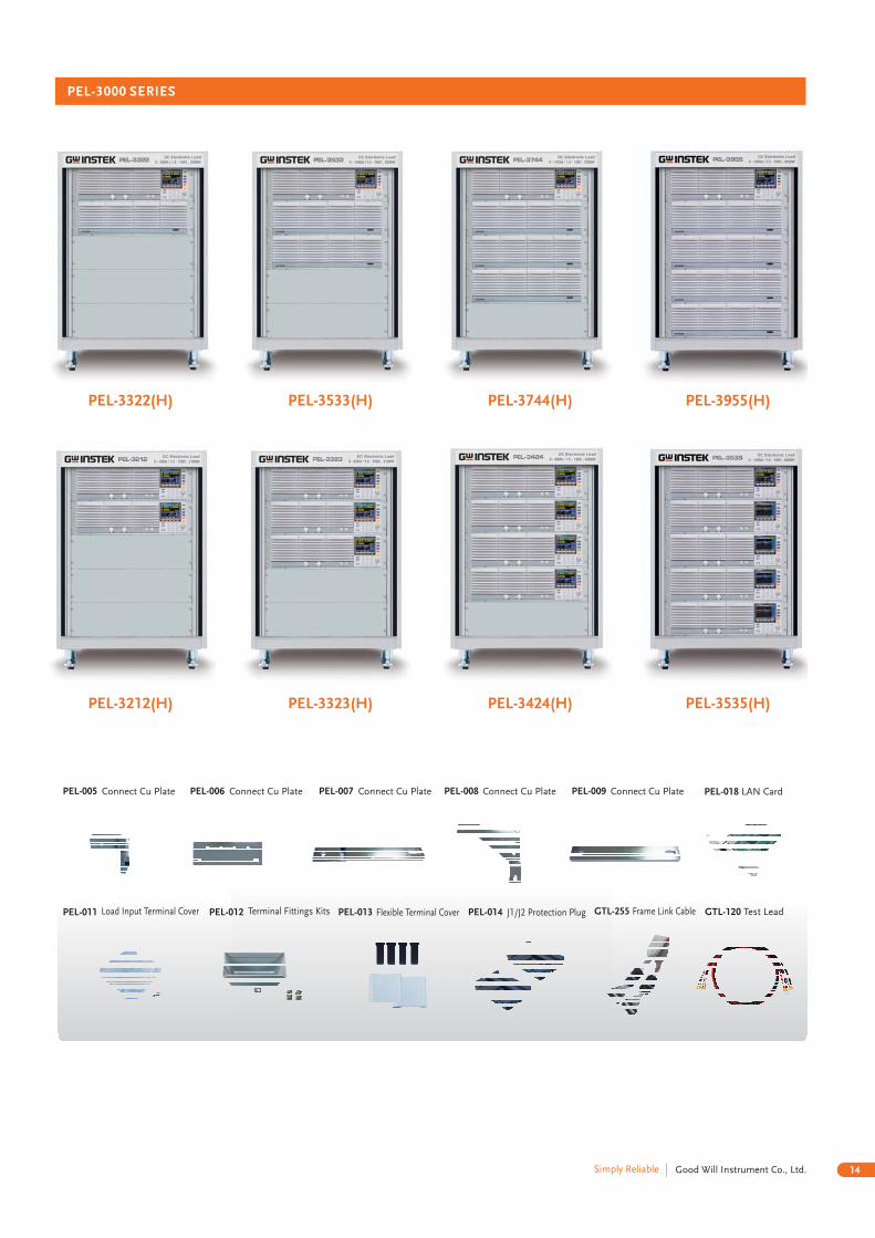
PEL-3000 SERIES
PEL-3744(H)PEL-3533(H)PEL-3322(H)
PEL-3424(H) PEL-3535(H)PEL-3323(H)PEL-3212(H)
J1/J2 Protection PlugPEL-013 Flexible Terminal CoverPEL-012 Terminal Fittings KitsPEL-011 Load Input Terminal Cover PEL-014 GTL-120 Test LeadGTL-255 Frame Link Cable
PEL-3955(H)
PEL-018 LAN Card