Embed Size (px)
Citation preview

Flexible Solutions for Your Supervisory Control and Data Acquisition Needs
SCADA System Selection Guide

Important User Information
Read this document and the documents listed in the additional resources section about installation, configuration, and operation of this equipment before you install, configure, operate, or maintain this product. Users are required to familiarize themselves with installation and wiring instructions in addition to requirements of all applicable codes, laws, and standards.
Activities including installation, adjustments, putting into service, use, assembly, disassembly, and maintenance are required to be carried out by suitably trained personnel in accordance with applicable code of practice.
If this equipment is used in a manner not specified by the manufacturer, the protection provided by the equipment may be impaired.
In no event will Rockwell Automation, Inc. be responsible or liable for indirect or consequential damages resulting from the use or application of this equipment.
The examples and diagrams in this manual are included solely for illustrative purposes. Because of the many variables and requirements associated with any particular installation, Rockwell Automation, Inc. cannot assume responsibility or liability for actual use based on the examples and diagrams.
No patent liability is assumed by Rockwell Automation, Inc. with respect to use of information, circuits, equipment, or software described in this manual.
Reproduction of the contents of this manual, in whole or in part, without written permission of Rockwell Automation, Inc., is prohibited.
Throughout this manual, when necessary, we use notes to make you aware of safety considerations.
Labels may also be on or inside the equipment to provide specific precautions.
Allen-Bradley, Rockwell Software, and Rockwell Automation are trademarks of Rockwell Automation, Inc.
Trademarks not belonging to Rockwell Automation are property of their respective companies.
WARNING: Identifies information about practices or circumstances that can cause an explosion in a hazardous environment, which may lead to personal injury or death, property damage, or economic loss.
ATTENTION: Identifies information about practices or circumstances that can lead to personal injury or death, property damage, or economic loss. Attentions help you identify a hazard, avoid a hazard, and recognize the consequence.
IMPORTANT Identifies information that is critical for successful application and understanding of the product.
SHOCK HAZARD: Labels may be on or inside the equipment, for example, a drive or motor, to alert people that dangerous voltage may be present.
BURN HAZARD: Labels may be on or inside the equipment, for example, a drive or motor, to alert people that surfaces may reach dangerous temperatures.
ARC FLASH HAZARD: Labels may be on or inside the equipment, for example, a motor control center, to alert people to potential Arc Flash. Arc Flash will cause severe injury or death. Wear proper Personal Protective Equipment (PPE). Follow ALL Regulatory requirements for safe work practices and for Personal Protective Equipment (PPE).

Summary of Changes
This manual contains new and updated information. Changes throughout this revision are marked by change bars, as shown to the right of this paragraph.
New and Updated Information
This table contains the changes made to this revision.
Topic Page
Updated the device selection table. 72
Rockwell Automation Publication AG-SG001G-EN-P - April 2015 3

Summary of Changes
Notes: To download or view a .doc file version of this procurement specification, please visit: www.rockwellautomation.com/industries/procurement-specifications.
4 Rockwell Automation Publication AG-SG001G-EN-P - April 2015

Table of Contents
Summary of Changes New and Updated Information. . . . . . . . . . . . . . . . . . . . . . . . . . . . . . . . . . . . . . 3Table of Contents
Preface How to Use This Document . . . . . . . . . . . . . . . . . . . . . . . . . . . . . . . . . . . . . . . . 9Additional Resources . . . . . . . . . . . . . . . . . . . . . . . . . . . . . . . . . . . . . . . . . . . . . . . 9
Chapter 1
Your SCADA System
Solutions
What Is SCADA? . . . . . . . . . . . . . . . . . . . . . . . . . . . . . . . . . . . . . . . . . . . . . . . . 11Variety of Applications . . . . . . . . . . . . . . . . . . . . . . . . . . . . . . . . . . . . . . . . . . . 12
Water and Wastewater SCADA Application . . . . . . . . . . . . . . . . . . . 12Oil and Gas Production SCADA Application . . . . . . . . . . . . . . . . . . 14
System Flexibility . . . . . . . . . . . . . . . . . . . . . . . . . . . . . . . . . . . . . . . . . . . . . . . . 16Products Designed for SCADA Applications . . . . . . . . . . . . . . . . . . . . . . . 16
Scalability. . . . . . . . . . . . . . . . . . . . . . . . . . . . . . . . . . . . . . . . . . . . . . . . . . . . 16Integral Communication. . . . . . . . . . . . . . . . . . . . . . . . . . . . . . . . . . . . . . 17FactoryTalk View Site Edition Software . . . . . . . . . . . . . . . . . . . . . . . . 17
Control System Experience . . . . . . . . . . . . . . . . . . . . . . . . . . . . . . . . . . . . . . . 17Support . . . . . . . . . . . . . . . . . . . . . . . . . . . . . . . . . . . . . . . . . . . . . . . . . . . . . . . . . 18Securing SCADA and Control Systems . . . . . . . . . . . . . . . . . . . . . . . . . . . . 18Select System Components . . . . . . . . . . . . . . . . . . . . . . . . . . . . . . . . . . . . . . . 18Selection Worksheet . . . . . . . . . . . . . . . . . . . . . . . . . . . . . . . . . . . . . . . . . . . . . 20
Chapter 2
Choosing a Telemetry
Network
Overview . . . . . . . . . . . . . . . . . . . . . . . . . . . . . . . . . . . . . . . . . . . . . . . . . . . . . . . . 21Choosing a Topology . . . . . . . . . . . . . . . . . . . . . . . . . . . . . . . . . . . . . . . . . . . . . 22
Point-to-point . . . . . . . . . . . . . . . . . . . . . . . . . . . . . . . . . . . . . . . . . . . . . . . 22Point-to-multipoint (multidrop) . . . . . . . . . . . . . . . . . . . . . . . . . . . . . . 22Multipoint-to-multipoint . . . . . . . . . . . . . . . . . . . . . . . . . . . . . . . . . . . . . 23
Choosing a Transmission Mode . . . . . . . . . . . . . . . . . . . . . . . . . . . . . . . . . . . 24Choosing a Link Media . . . . . . . . . . . . . . . . . . . . . . . . . . . . . . . . . . . . . . . . . . . 24
Public-switched Telephone Network (PSTN) or General Switched Telephone Network (GSTN) . . . . . . . . . . . . . . . . . . . . . . . . . . . . . . . . . 25Private Leased Line (PLL) . . . . . . . . . . . . . . . . . . . . . . . . . . . . . . . . . . . . . 26Digital Data Services (DDS). . . . . . . . . . . . . . . . . . . . . . . . . . . . . . . . . . . 27Internet via Internet Service Provider (ISP) . . . . . . . . . . . . . . . . . . . . . 28Microwave Radio . . . . . . . . . . . . . . . . . . . . . . . . . . . . . . . . . . . . . . . . . . . . . 28VHF/UHF Radio . . . . . . . . . . . . . . . . . . . . . . . . . . . . . . . . . . . . . . . . . . . . 29Geosynchronous Satellite . . . . . . . . . . . . . . . . . . . . . . . . . . . . . . . . . . . . . 30Cellular Network. . . . . . . . . . . . . . . . . . . . . . . . . . . . . . . . . . . . . . . . . . . . . 31Dedicated Wire . . . . . . . . . . . . . . . . . . . . . . . . . . . . . . . . . . . . . . . . . . . . . . 32Power Line. . . . . . . . . . . . . . . . . . . . . . . . . . . . . . . . . . . . . . . . . . . . . . . . . . . 32
Choosing a Protocol . . . . . . . . . . . . . . . . . . . . . . . . . . . . . . . . . . . . . . . . . . . . . . 33DF1 Half-duplex Protocol . . . . . . . . . . . . . . . . . . . . . . . . . . . . . . . . . . . . 33DF1 Radio Modem Protocol . . . . . . . . . . . . . . . . . . . . . . . . . . . . . . . . . . 34DF1 Full-duplex Protocol . . . . . . . . . . . . . . . . . . . . . . . . . . . . . . . . . . . . . 34Ethernet/Industrial Protocol (EtherNet/IP) . . . . . . . . . . . . . . . . . . . . 34
Rockwell Automation Publication AG-SG001G-EN-P - April 2015 5

Table of Contents
DNP3 . . . . . . . . . . . . . . . . . . . . . . . . . . . . . . . . . . . . . . . . . . . . . . . . . . . . . . . 35Other Protocols . . . . . . . . . . . . . . . . . . . . . . . . . . . . . . . . . . . . . . . . . . . . . . 36
Securing the Telemetry Network . . . . . . . . . . . . . . . . . . . . . . . . . . . . . . . . . . 38What To Do Next. . . . . . . . . . . . . . . . . . . . . . . . . . . . . . . . . . . . . . . . . . . . . . . . 39
Chapter 3
Choosing Data
Communication Equipment
Overview . . . . . . . . . . . . . . . . . . . . . . . . . . . . . . . . . . . . . . . . . . . . . . . . . . . . . . . . 41Choosing a Telephone Modem . . . . . . . . . . . . . . . . . . . . . . . . . . . . . . . . . . . . 42
Analog Dial-up Modem . . . . . . . . . . . . . . . . . . . . . . . . . . . . . . . . . . . . . . . 43Analog Leased-line Modems . . . . . . . . . . . . . . . . . . . . . . . . . . . . . . . . . . . 44Digital Leased-line ISUs . . . . . . . . . . . . . . . . . . . . . . . . . . . . . . . . . . . . . . . 45Telephone Modem and ISU Installation Guidelines . . . . . . . . . . . . . 46
Choosing a Radio Transmission System . . . . . . . . . . . . . . . . . . . . . . . . . . . . 46Licensing. . . . . . . . . . . . . . . . . . . . . . . . . . . . . . . . . . . . . . . . . . . . . . . . . . . . . 47Radio Modem Types . . . . . . . . . . . . . . . . . . . . . . . . . . . . . . . . . . . . . . . . . . 49Radio Modem Installation Guidelines . . . . . . . . . . . . . . . . . . . . . . . . . . 53
Choosing a SatelliteTransmission System . . . . . . . . . . . . . . . . . . . . . . . . . . . . . . . . . . . . . . . . . . . . . 53
Single-Hop . . . . . . . . . . . . . . . . . . . . . . . . . . . . . . . . . . . . . . . . . . . . . . . . . . . 53Double-hop . . . . . . . . . . . . . . . . . . . . . . . . . . . . . . . . . . . . . . . . . . . . . . . . . . 54
Choosing Dedicated Wire/Power Line Modems . . . . . . . . . . . . . . . . . . . . 55Choosing a Cellular Transmission System . . . . . . . . . . . . . . . . . . . . . . . . . . 55
Cellular Network Architecture. . . . . . . . . . . . . . . . . . . . . . . . . . . . . . . . . 55Managing Cost of a Cellular Network Data Charges . . . . . . . . . . . . . 57Determining Monthly Cost for Data Usage . . . . . . . . . . . . . . . . . . . . . 58Advantages and Disadvantages over other Modem Technologies . . 59
What To Do Next. . . . . . . . . . . . . . . . . . . . . . . . . . . . . . . . . . . . . . . . . . . . . . . . 59
Chapter 4
Choosing a Device for a
Master Station
Overview . . . . . . . . . . . . . . . . . . . . . . . . . . . . . . . . . . . . . . . . . . . . . . . . . . . . . . . . 61Choosing a Computer-based Master Station . . . . . . . . . . . . . . . . . . . . . . . . 63
Using FactoryTalk View SE Software as a Master Station. . . . . . . . . 63Using FactoryTalk View SE Software as a Plant HMI . . . . . . . . . . . . 64
Choosing a ProgrammableController-basedMaster Station . . . . . . . . . . . . . . . . . . . . . . . . . . . . . . . . . . . . . . . . . . . . . . . . . . . 65Choosing a Data-concentrating Submaster Station . . . . . . . . . . . . . . . . . . 66Choosing a Data-routing Submaster Station . . . . . . . . . . . . . . . . . . . . . . . . 67Needed Equipment . . . . . . . . . . . . . . . . . . . . . . . . . . . . . . . . . . . . . . . . . . . . . . . 69Installation Guidelines . . . . . . . . . . . . . . . . . . . . . . . . . . . . . . . . . . . . . . . . . . . . 69What To Do Next. . . . . . . . . . . . . . . . . . . . . . . . . . . . . . . . . . . . . . . . . . . . . . . . 69
6 Rockwell Automation Publication AG-SG001G-EN-P - April 2015

Table of Contents
Chapter 5
Choosing a Device for a
Remote Station
Overview . . . . . . . . . . . . . . . . . . . . . . . . . . . . . . . . . . . . . . . . . . . . . . . . . . . . . . . . 71Choose a Device . . . . . . . . . . . . . . . . . . . . . . . . . . . . . . . . . . . . . . . . . . . . . . . . . 72Needed Equipment. . . . . . . . . . . . . . . . . . . . . . . . . . . . . . . . . . . . . . . . . . . . . . . 73Installation Guidelines. . . . . . . . . . . . . . . . . . . . . . . . . . . . . . . . . . . . . . . . . . . . 73What To Do Next . . . . . . . . . . . . . . . . . . . . . . . . . . . . . . . . . . . . . . . . . . . . . . . 74
Appendix A
Third-party Supplier Contact
Information
Introduction. . . . . . . . . . . . . . . . . . . . . . . . . . . . . . . . . . . . . . . . . . . . . . . . . . . . . 75Contact List . . . . . . . . . . . . . . . . . . . . . . . . . . . . . . . . . . . . . . . . . . . . . . . . . . . . . 76
Glossary
Rockwell Automation Publication AG-SG001G-EN-P - April 2015 7

Table of Contents
8 Rockwell Automation Publication AG-SG001G-EN-P - April 2015
Preface
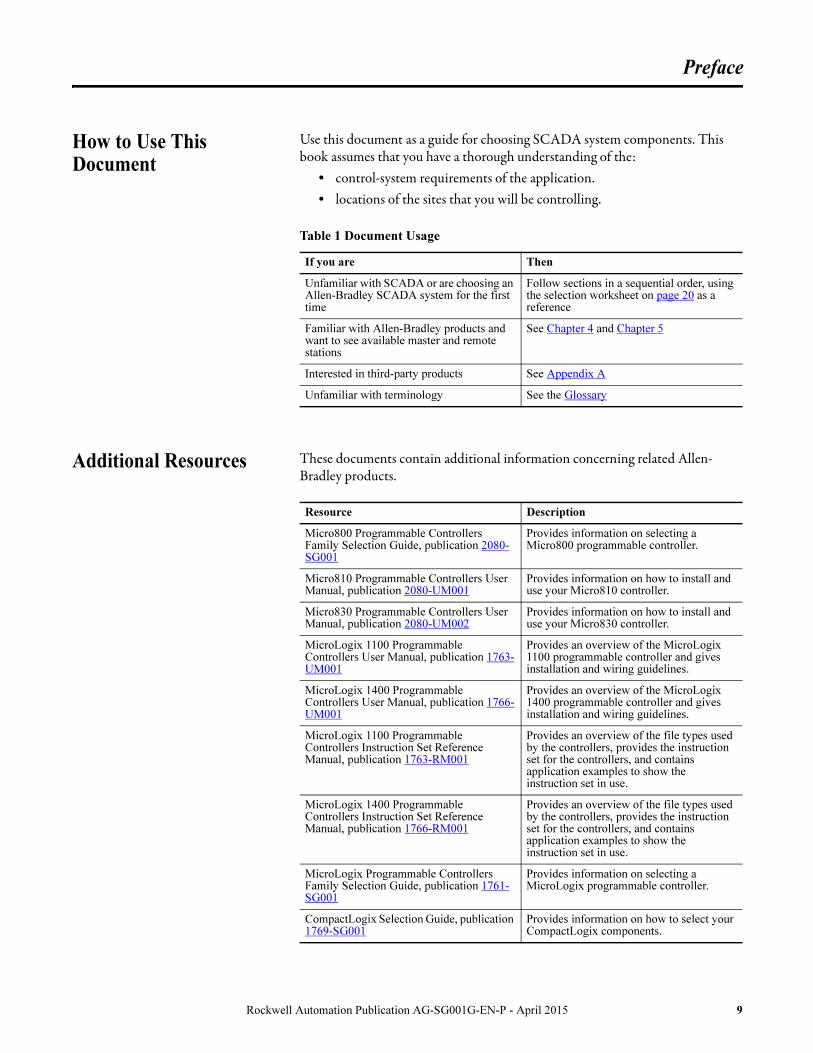
How to Use This Document
Use this document as a guide for choosing SCADA system components. This book assumes that you have a thorough understanding of the:
• control-system requirements of the application.• locations of the sites that you will be controlling.
Additional Resources These documents contain additional information concerning related Allen-Bradley products.
Table 1 Document Usage
If you are Then
Unfamiliar with SCADA or are choosing an Allen-Bradley SCADA system for the first time
Follow sections in a sequential order, using the selection worksheet on page 20 as a reference
Familiar with Allen-Bradley products and want to see available master and remote stations
See Chapter 4 and Chapter 5
Interested in third-party products See Appendix A
Unfamiliar with terminology See the Glossary
Resource Description
Micro800 Programmable Controllers Family Selection Guide, publication 2080-SG001
Provides information on selecting a Micro800 programmable controller.
Micro810 Programmable Controllers User Manual, publication 2080-UM001
Provides information on how to install and use your Micro810 controller.
Micro830 Programmable Controllers User Manual, publication 2080-UM002
Provides information on how to install and use your Micro830 controller.
MicroLogix 1100 Programmable Controllers User Manual, publication 1763-UM001
Provides an overview of the MicroLogix 1100 programmable controller and gives installation and wiring guidelines.
MicroLogix 1400 Programmable Controllers User Manual, publication 1766-UM001
Provides an overview of the MicroLogix 1400 programmable controller and gives installation and wiring guidelines.
MicroLogix 1100 Programmable Controllers Instruction Set Reference Manual, publication 1763-RM001
Provides an overview of the file types used by the controllers, provides the instruction set for the controllers, and contains application examples to show the instruction set in use.
MicroLogix 1400 Programmable Controllers Instruction Set Reference Manual, publication 1766-RM001
Provides an overview of the file types used by the controllers, provides the instruction set for the controllers, and contains application examples to show the instruction set in use.
MicroLogix Programmable Controllers Family Selection Guide, publication 1761-SG001
Provides information on selecting a MicroLogix programmable controller.
CompactLogix Selection Guide, publication 1769-SG001
Provides information on how to select your CompactLogix components.
Rockwell Automation Publication AG-SG001G-EN-P - April 2015 9

Preface
You can view or download publications at http://www.rockwellautomation.com/literature/. To order paper copies of technical documentation, contact your local Allen-Bradley distributor or Rockwell Automation sales representative.
ControlLogix Controllers User Manual, publication 1756-UM001
Provides information on the ControlLogix controller including its features.
Logix5000 Controllers Common Procedures Manual, publication 1756-PM001
Provides links to other ControlLogix information.
ControlLogix Selection Guide, publication 1756-SG001
Provides information on how to select your ControlLogix controller.
Resource Description
10 Rockwell Automation Publication AG-SG001G-EN-P - April 2015

Chapter 1
Your SCADA System Solutions
What Is SCADA? SCADA is an acronym for Supervisory Control and Data Acquisition. Use this book as a guide for choosing SCADA system components. If you are already familiar with SCADA, go to page 18.
SCADA systems let you monitor and control various remote functions and processes by using modem communication links between master and remote locations.
Figure 1 - SCADA System Overview
or
Pump StationWaste Treatment Plant
Gas Metering StationPump Station
Master Station
Remote StationRemote Station
Remote StationRemote Station
Modem
Modem
Modem
Modem
Modem
MicroLogix
MicroLogix
SLC
Etherne
ControlLogi
Etherne
Clarifying
Deck
CompactLogi
SLC 5/05
PanelView
Rockwell Automation Publication AG-SG001G-EN-P - April 2015 11

Chapter 1 Your SCADA System Solutions
Variety of Applications There are a variety of SCADA applications:• Water and wastewater applications• Oil and gas production
Water and Wastewater SCADA Application
These applications use lift stations and water booster stations.
Lift Stations
Collection systems rely on a series of lift stations and combined sewer overflow (CSO) stations communicating to a central location to prevent sewerage back-ups and protect the environment.
Water Booster Stations
Booster pump stations for fresh water systems operate by maintaining system pressure or matching water-flow demand.
12 Rockwell Automation Publication AG-SG001G-EN-P - April 2015

Your SCADA System Solutions Chapter 1
Figure 2 - Water and Wastewater SCADA Applications
SLC 500
Town
Local Sewers
Industrial WastePre-treatment
Secondary Sludge Digestion
IndustrialCollection
Sludge Disposal
Sludge Digestion
Incinerator
Final Sedimentation
Effluent Pumping
Outfall
Dispersion
SCADA
Master
Trunk Servers
Grit Removal
CompactLogix
Primary Sedimentation Tanks Aeration
Storage Reservoir
Inlet Tower
Outlet Tower
Elevated Tank
High Service Pumping
Main Control
Influent Pumping Disinfection
SCADA Master
POWER
ETHERN ET
RXD TXD OK
PROGRUN REM
RUN I/O
RS2 32
BAT OK
L ogix5 550
B A
OK
AB
Control NET
A # 2 4
DIAGNOSTIC
DC O UTPUT
F LT
ST
F LT
ST
OK
0 1 2 3 4 5 6 7
0 1 2 3 4 5 6 7
8 9 10 11 12 13 14 15
8 9 10 11 12 13 14 15
AC INPUT
ST
ST
OK
0 1 2 3 4 5 6 7
8 9 10 11 12 13 14 15
AC O UTPUT
DIAGNOSTIC
FLT
ST OK
0 1 2 3 4 5 6 7
0 1 2 3 4 5 6 7
DH +/RIO
CH A CH B OK
B # 1 5
Main PumpStation
Ethernet
Screening andPumping Station
Intake
Main Pump Station
Ethernet
Primary
FactoryTalk
View SE
Server
Secondary
FactoryTalk
View SE
Server
PowerFlex 700
PowerFlex 700
PowerFlex
700
PowerFlex
700
PowerFlex
700
MicroLogix
1100
MicroLogix 1100
MicroLogix 1100
DIAGNOSTI C
FLT
ST
FLT
ST
ST
ST
OK
0 1 2 3 4 5 6 7
0 1 2 3 4 5 6 7
8 9 10 11 12 13 14 15
8 9 10 11 12 13 14 15
OK
0 1 2 3 4 5 6 7
8 9 10 11 12 13 14 15
RXD TXD OK
DIAGNOSTI C
FLT
ST
FLT
ST
ST
ST
OK
0 1 2 3 4 5 6 7
0 1 2 3 4 5 6 7
8 9 10 11 12 13 14 15
8 9 10 11 12 13 14 15
OK
0 1 2 3 4 5 6 7
8 9 10 11 12 13 14 15
RXD TXD OK
ControlLogix
ControlLogix
POW ER
ETHE RNET
RXD TXD OK
PROGRUN REM
RUN I/O
RS23 2
BAT OK
L ogix5 550
B A
OK
AB
Control NET
A # 2 4
DIAGNO STI C
DC OUT PUT
FLT
ST
FLT
ST
OK
0 1 2 3 4 5 6 7
0 1 2 3 4 5 6 7
8 9 10 11 12 13 14 15
8 9 10 11 12 13 14 15
AC INPU T
ST
ST
OK
0 1 2 3 4 5 6 7
8 9 10 11 12 13 14 15
AC OUT PUT
DIAGNO STI C
FLT
ST OK
0 1 2 3 4 5 6 7
0 1 2 3 4 5 6 7
DH +/RIO
CH A CH B OK
B # 1 5
Pump Station RTU Pump Station RTU
Lift Station RTU
Lift Station RTU
Water Treatment Plant
Primary
FactoryTalk
View SE
Server
Secondary
FactoryTalk View SE
Server
Rockwell Automation Publication AG-SG001G-EN-P - April 2015 13

Chapter 1 Your SCADA System Solutions
Oil and Gas Production SCADA Application
Oil and Gas Wells
There are two main types of wells: Natural Flow and Artificial Lift wells. Monitoring and remote control requirements depend on the type of well. For natural flow well, surface process variables like flowing/casing pressure and temperatures and the position of the flowing valve need to be monitored and gas wells include compensated flow calculations. Remote control is limited to the shutdown valve. For artificial lift wells, additional monitoring and control is required to be able to supervise motor or gas lift valves and be able to control those devices.
Compressor Stations
Compressor Stations are responsible in pipeline systems for maintaining the appropriate pressure levels needed to deliver gas at the destination locations. Multiple compressor stations are typically needed in a gas pipeline and the communication to a central location is key ensure coordination and safety of the operation.
Valve Stations
An important element in the safe operation of a gas or liquid pipeline is the block or segmenting valves. These valves are mainly responsible for shutting down segments of the pipeline to isolate leaks or ruptures. Local and remote control capabilities as well as data acquisition functions to be able to collect process information along the pipeline (Pressure, temperature, flow, and valve position) are the main requirements of this application.
Pump Stations
Operate by maintaining system pressure or matching flow demand. Multiple pump stations connected to the pipeline and communicating back to a central location are used to deliver crude oil or products to refineries and terminals.
14 Rockwell Automation Publication AG-SG001G-EN-P - April 2015

Your SCADA System Solutions Chapter 1
Figure 3 - Oil and Gas Production SCADA Applications
POWER
ETH ERNET
RXD TXD OK
PROGRUN REM
RUN I/O
RS232
BAT OK
Logix5 550
B A
OK
AB
Contro lNET
A # 2 4
DIAGNOST IC
DC OUTPU T
FLT
ST
FLT
ST
OK
0 1 2 3 4 5 6 7
0 1 2 3 4 5 6 7
8 9 10 11 12 13 14 15
8 9 10 11 12 13 14 15
AC I NPUT
ST
ST
OK
0 1 2 3 4 5 6 7
8 9 10 11 12 13 14 15
AC O UTP UT
DIAGNOST IC
FLT
ST OK
0 1 2 3 4 5 6 7
0 1 2 3 4 5 6 7
DH +/R IO
CH A CH B OK
B # 1 5
DIA GNOS TIC
FLT
ST
FLT
S T
ST
ST
OK
0 1 2 3 4 5 6 7
0 1 2 3 4 5 6 7
8 9 10 11 12 13 14 15
8 9 10 11 12 13 14 15
OK
0 1 2 3 4 5 6 7
8 9 10 11 12 13 14 15
RXD TXD OK
DIA GNOS TIC
FLT
ST
FLT
S T
S T
S T
OK
0 1 2 3 4 5 6 7
0 1 2 3 4 5 6 7
8 9 10 11 12 13 14 15
8 9 10 11 12 13 14 15
OK
0 1 2 3 4 5 6 7
8 9 10 11 12 13 14 15
RXD TXD OK
DIA GNOS TIC
FLT
S T
FLT
ST
ST
ST
OK
0 1 2 3 4 5 6 7
0 1 2 3 4 5 6 7
8 9 10 11 12 13 14 15
8 9 10 11 12 13 14 15
OK
0 1 2 3 4 5 6 7
8 9 10 11 12 13 14 15
RXD TXD OK
Main Pump Station
Pump Station RTU
Valve Station RTU
Valve Station RTU
Compressor Station
RTU
Separator Facility RTU
Well RTU
Well RTU
ControlLogix
Ethernet
MicroLogix 1100
MicroLogix 1100
MicroLogix 1100
MicroLogix 1100
CompactLogix
CompactLogix
To Water Treatment
Oil Pipeline
Gas Pipeline
CompactLogix
PowerFlex 700
PowerFlex 700
PowerFlex 700
Storage
To Storage
To Refinery
Compressor CompressorMetering
Pumping/Metering
Primary
FactoryTalk
View SE
Server
Secondary
FactoryTalk
View SE
Server
Rockwell Automation Publication AG-SG001G-EN-P - April 2015 15

Chapter 1 Your SCADA System Solutions
System Flexibility Rockwell Automation has developed a close relationship with several companies who supply SCADA-related hardware and software. Through the Encompass Program, we reference hardware and software companies that provide additional products to meet your application needs. We review each company to make certain it provides the quality and service you deserve. For the latest information, refer to the Encompass Program Product Directory, at:http://www.rockwellautomation.com/encompass.
Products Designed for SCADA Applications
Key features built into Allen-Bradley products help provide a one-stop SCADA solution.
Scalability
Choose from many sizes of programmable controllers to meet master station and remote station control needs.
• Select one or more ControlLogix processors in a chassis with one or more Ethernet, ControlNet, and/or DeviceNet communication modules to fit your most demanding master station and remote station requirements in single or redundant configurations.
• Select a CompactLogix L3x or L4x controller to fit your small to medium master station and/or remote station applications that require Store & Forward and/or true Report-by-Exception capabilities.
• Select a MicroLogix 1400 or CompactLogix L2x controller to fit your small to medium master and/or remote station applications that require Store & Forward and/or true Report-by-Exception capabilities.
• Select a MicroLogix 1100 or Micro800 to fit your small remote station applications.
• Select a DataSite RTU to fit your extreme temperature or low-power remote-station applications.
16 Rockwell Automation Publication AG-SG001G-EN-P - April 2015

Your SCADA System Solutions Chapter 1
Integral Communication
Built-in communication support means less equipment to buy.
• Choose versions of ControlLogix, CompactLogix, MicroLogix, or Micro800 controllers that have built-in or plug-in serial ports.
• Select a CompactLogix LxxE, MicroLogix 1100/1400, or Micro850 controller for built-in Ethernet connectivity that uses standard TCP/IP protocol.
FactoryTalk View Site Edition Software
Fulfill your SCADA computer software needs using Rockwell Software FactoryTalk View SE software.
• Using FactoryTalk View SE software, additional workstations can be clients to the FactoryTalk View SE Servers across a local-area or wide-area Ethernet network. FactoryTalk View SE software also supports redundant configurations for maximum system availability.
• Add RSLogix programming software, and the workstation can become the system programming terminal for both local and remote stations.
• Add Encompass Partner value-add software such as Specter Instruments WIN-911 Alarm Notification software.
Control System Experience
Our many years of control system experience and broad product line can provide you with a total system solution. Choose from our many:
• push-buttons and switches.• programmable controllers.• I/O modules.• operator interfaces.• development software packages.• industrialized computers.• specialized PLC-based hardware and software that support process
control, motion control, and AC/DC drives.
Rockwell Automation Publication AG-SG001G-EN-P - April 2015 17

Chapter 1 Your SCADA System Solutions
Support We offer a world-wide technical support network to answer your questions.
• Rockwell Automation Technical Support provides help via telephone or at your control sites.
• Allen-Bradley local distributors provide quick turnaround on your orders and local support.
• Allen-Bradley and Rockwell Software product training courses are available. Contact your local Rockwell Automation sales office or Allen-Bradley distributor for information.
Securing SCADA and Control Systems
A robust security strategy is both broad and deep in the enhanced protection it facilitates in control system safety and operational integrity. The scope of a truly expansive industrial security solution includes the control system and its constituent products, but also the people, policies, and procedures necessary to maintain a specific level of security. Expert consulting services can often help assure a more thorough and complete evaluation of security posture. Rockwell Automation Network and Security Services group has the expertise and know-how to help address industrial security concerns in a balanced way.
For more information about Rockwell Automation Industrial Security position and capabilities, including Network and Security Services, visit http://www.rockwellautomation.com/security.
Select System Components
Each section in this publication (and in the worksheet on page 20) describes a specific component and presents selection criteria to help you make appropriate choices for your application.
Follow this procedure to select SCADA system components.
1. Choose a telemetry network (if not specified).
2. Choose data communication equipment (DCE).
3. Choose a master station and (if necessary) an operator interface.
4. Choose remote stations for the local control sites.
5. For modular processors, choose appropriate input/output modules to monitor and control the application.
18 Rockwell Automation Publication AG-SG001G-EN-P - April 2015

Your SCADA System Solutions Chapter 1
Figure 4 - SCADA System Components
3. Master Station
2. DCE
1. Telemetry Network
4. Remote Station 4. Remote Station5. Modular Processor
with I/O
Rockwell Automation Publication AG-SG001G-EN-P - April 2015 19

Chapter 1 Your SCADA System Solutions
Selection Worksheet Use this worksheet as a quick guide to specifying a system.
Step For this component Choose See page Record your selection
1
Telemetry network Topology:• Point-to-point• Point-to-multipoint• Multipoint-to-multipoint
22
Transmission mode:• Half-duplex• Full-duplex
24
Link media 24
Protocol 33
2
Data communication equipment
Choose DCEs based on the following:• Link media• Transmission requirements• Diagnostic requirements• Master and remote station needs• Application
41
3
Master station Choose a master station based on the following:• Functionality required (I/O to scan, amount of data to be
collected, operator interface needed)• Quantity of remote stations • Protocol being used• Other application requirements
Make sure you have the following:• A serial and/or Ethernet interface• The proper equipment for the protocol you are using• Power for the station
Select other components you may need:• I/O modules and chassis• Local area network components• Enclosures
61
Operator interfacesubmaster station
Depending on the size of your application, you may need operator interfaces or submaster stations.
66
4
Remote stations Choose a remote station based on the following:• Functionality required• Quantity of I/O points being controlled• Power availability• Space• Location of the remote station• Other application requirements
71
5
Choose control system components:• I/O modules and chassis• Enclosures• Operator interfaces
20 Rockwell Automation Publication AG-SG001G-EN-P - April 2015

Chapter 2
Choosing a Telemetry Network
Overview A telemetry network provides the communication pathway in a SCADA system. Topologies, transmission modes, link media, and protocols make up a telemetry network.
An application can have more than one telemetry network. In some critical applications, you may want to design a back-up system or recovery procedure for your main network. Analyze your requirements and select telemetry networks accordingly.
Design the network by selecting each component.
transmit
DF1
DF1
DF1 DF1 DF1
Master Station
Data Communication Equipment
TransmitTopology
Point-to-point
Topology
Point-to-multipoint
Link Media Link Media Link Media
Transmission Mode:
Transmit
Receive Transmit
Receive
Receive Receive
Remote Station Remote Station Remote Station
Transmission Mode:
Half-duplex
Protocol: DF1Protocol: DF1
Full-duplex
Topic Page
Choosing a Topology 22
Choosing a Transmission Mode 24
Choosing a Link Media 24
Choosing a Protocol 33
Rockwell Automation Publication AG-SG001G-EN-P - April 2015 21

Chapter 2 Choosing a Telemetry Network
Choosing a Topology Topology is the geometric arrangement of nodes and links that make up a network. For a SCADA system, choose among point-to-point, point-to-multipoint, and multipoint-to-multipoint topologies.
Point-to-point
Point-to-point is a communication link between only two stations, where either station can initiate communication with the other, or one station can inquire and control the other.
Stations can be connected using: • cables or permanent public media like leased telephone lines or digital data
services.• temporary connections, such as dial-up lines or microwave, radio, or
satellite transmissions.
Point-to-point is generally a 2-wire connection, with the transmission media using two wires for signal transmission/reception. Since a public-switched telephone network (PSTN) provides a 2-wire connection, the topology used for a dial-up line is 2-wire point-to-point.
Point-to-multipoint (multidrop)
Point-to-multipoint is a communication link among three or more stations with one station being a communication arbitrator (master) that controls when the other stations (remote stations) can communicate.
The stations can be connected using: • permanent public media like leased lines or digital data services.• atmospheric connections, such as microwave, radio, or satellite
transmissions.
TIP Choose this topology if you need a peer-to-peer communication
connection, such as a back-up communication link between
remote stations at a site and the master station at the control site.
Station StationModemModem
DTEDCE DCE
Modem
Modem Modem
Master
Remote Remote
22 Rockwell Automation Publication AG-SG001G-EN-P - April 2015

Choosing a Telemetry Network Chapter 2
Point-to-multipoint connections are generally four-wire connections, with the transmission media using four wires for signal transmission/reception: one pair to transmit and one pair to receive. Private leased lines and digital data services provide four-wire, point-to-multipoint connections.
Multipoint-to-multipoint
Multipoint-to-multipoint is a radio modem communication link among three or more stations where there is no communication arbitrator (master) and any station can initiate communication with any other station.
This is the topology used by spread-spectrum Ethernet radio modems. It provides a peer-to-peer network among stations.
TIP Point-to-multipoint is the main topology for SCADA
applications.
Station Station
Radio Modem Radio
Modem
Station Station
Radio Modem Radio
Modem
Rockwell Automation Publication AG-SG001G-EN-P - April 2015 23

Chapter 2 Choosing a Telemetry Network
Choosing a Transmission Mode
The transmission mode defines the way information is sent and received between and/or among devices on a network. For SCADA systems, your network topology generally determines your data transmission mode.
Choosing a Link Media When choosing link media, consider the following:
• Data transmission needs of the application• Remote site and control center locations• Distance between sites• Available link media services • Project budget
Several types of link media are available, including public transmission media, atmospheric media, and dedicated line media.
The following sections outline the advantages, disadvantages, and requirements of each link medium.
If you have chosen this topology
Then your transmission mode is Which means
Point-to-multipoint Half-duplex Information is sent in one direction at a time over the link.
Point-to-point Full-duplex Information is simultaneously sent and received over the link.
Multipoint-to-multipoint Full-duplex (between station and modem) Half-duplex (between modems)
Information is simultaneously sent and received over the station to modem link, whereas information is sent in only one direction at a time over the modem to modem link.
Station
A
Station
B
transmit
receive
receive
transmit
Station
A
Station
B
transmit
receive
receive
transmit
Station
A
Modem
A
transmit
receive
receive
transmit
Modem
B
transmit
receive
receive
transmit
Station
Breceive
receive
transmit
Media Category Type
Public transmission media
• Public-switched telephone network (PSTN); Internationally: general switched telephone network (GSTN)
• Private leased line (PLL)• Digital data service (DDS)• Internet via ISP
Atmospheric media • Microwave radio• VHF/UHF radio• Geosynchronous satellite• Cellular network
Dedicated line • Dedicated wire• Power line
24 Rockwell Automation Publication AG-SG001G-EN-P - April 2015

Choosing a Telemetry Network Chapter 2
Public-switched Telephone Network (PSTN) or General
Switched Telephone Network (GSTN)
The dial-up network is furnished by a telephone company. This telephone line is the one that we use daily and that carries voice and data transmissions.
Advantages/Capabilities
• Public-switched telephone networks are cost-effective for:– short, occasional data collection from remote sites that have access to a
PSTN. – sites calling in to a central location.
• Often point-to-point applications have a dial-up connection as a backup to the main media link.
• The phone company charges a monthly fee based on usage – the number of local connections made and/or the time and distance of each long distance connection.
• The network supports communication rates of up to 57,600 bps.
• The network is a 2-wire connection that supports half-duplex modems and 2-wire, full-duplex modems. The topology is point-to-point.
Disadvantages
• Transmission is costly for long, frequent data collection from remote sites.
• The lines can contain impairments that can cause modems to have error rates of less than 1 error per 1,000,000 bits.
• The media cannot be used in areas that do not have access to the network, such as an offshore oil or gas well.
• Time is required to dial and establish each connection.
• Additional logic is required to automatically initiate a connection.
Equipment Required
Use standard Bell or Consultive Committee for International Telephone and Telegraph (CCITT) modems. Contact the telephone company for information about connecting to the network.
% %
Rockwell Automation Publication AG-SG001G-EN-P - April 2015 25

Chapter 2 Choosing a Telemetry Network
Private Leased Line (PLL)
PLL is a dedicated telephone line that is a permanent connection between two or more locations and that is used for analog data transmission. The line is available 24 hours a day. In order for the line to be used for voice communication, a voice option must be installed.
Advantages/Capabilities
• The media is cost-effective for applications that require large amounts of data to be collected frequently from remote sites and/or applications that require remote sites to have a constant connection to the master station.
• Regardless of how much you use the line, the phone company charges you a flat, monthly fee based on the following:
– Distance between sites– Area of the country– Type of line conditioning
Leased lines have different levels of conditioning, or grades - the higher the grade, the greater the modem data rate that can be supported by the link, and the more the phone company charges for it.
• The standard, unconditioned line, supports speeds of up to 56 Kbps.
• Private leased lines provide a 4-wire connection. You can purchase modems that operate the circuit in either half- or full-duplex mode. You can also order a 4-wire multi-drop line.
Disadvantages
• The media cannot be used in areas that do not have access to the network, such as an offshore oil or gas well.
• The lines can contain impairments that can cause modems to have error rates of less than 1 error per 1,000,000 bits.
Equipment Required
Use standard Bell or CCITT modems. Contact the telephone company for information about connecting to the network.
Phone Company
PLL PLL
26 Rockwell Automation Publication AG-SG001G-EN-P - April 2015

Choosing a Telemetry Network Chapter 2
Digital Data Services (DDS)
DDS is a special wide-bandwidth private leased line that uses digital techniques to transfer data at higher speeds and at a lower error rate than private leased lines. The line is available 24 hours a day.
Advantages/Capabilities
• DDS is a digital network that offers higher transmission rates and minimal, if any, line impairments.
• The media is useful when an application requires very large amounts of data to be transferred between sites with a low data error rate.
• Regardless of use, the phone company charges you a flat, monthly fee based on the following:
– Distance between sites– Area of the country– Speed of the integrated service unit (digital ‘modem’)
• A constant connection exists.
• Asynchronous communication rates are 2.4 K, 4.8 K, 9.6 K, 19.2 K, 38.4 K, and 57.6 Kbps.
• The network provides a four-wire connection and can be configured in a multi-drop topology.
Disadvantage
The media is costly for applications not needing to transmit large amounts of data quickly and at a low data error rate.
Equipment Required
Use standard integrated service unit, ISU (also called a data service unit [DSU] or channel service unit [CSU]). The ISU data rate must match that of the digital data service line, which operates at a fixed rate.
Phone Company
DDS DDS
Rockwell Automation Publication AG-SG001G-EN-P - April 2015 27

Chapter 2 Choosing a Telemetry Network
Internet via Internet Service Provider (ISP)
Advantages/Capabilities
• High-speed broadband Ethernet network connections readily available in metropolitan areas
• Low monthly fixed cost for continuous data connections• Minimal capital costs• Remote access possible to/from anywhere on the Internet
Disadvantages
• Dependent on a public network (may not be available when needed most)• Requires network security precautions to prevent unauthorized access
Equipment Required
• Ethernet router/modem (typically provided by ISP)• Ethernet security hardware (for example, firewall or VPN)
Microwave Radio
Microwave radio is a high-frequency (GHz), terrestrial radio transmission and reception media that uses parabolic dishes as antennas. The dishes are usually mounted on towers or on top of tall buildings, since this is a line-of-sight topology.
Advantages/Capabilities
• The media links geographically-remote areas that are not accessible by phone lines.
• A constant connection exists.• Transmissions can occur over very long distances over rough terrain.• You incur no monthly service fee because you own the equipment. The
only expenses are operation and maintenance costs.• Low transmission delay times exist.• The larger bandwidth allows you to multiplex many channels over one
antenna.• Lease circuits from another company who owns their own private
microwave circuit.
28 Rockwell Automation Publication AG-SG001G-EN-P - April 2015

Choosing a Telemetry Network Chapter 2
Disadvantages
• Transmission is limited to a line-of-sight, for example, you cannot transmit through mountains. The signal can experience distortion and interference. Also, atmospheric conditions such as rain, snow, or fog can affect the signal.
• Most microwave link frequencies are allocated and regulated by the Federal Communications Commission (FCC). In urban areas, fewer data-transmission frequencies are available.
• You can incur large initial expense for equipment.
Equipment Required
• Transmitters• Receivers• Parabolic dish antennas• Repeaters are needed to transmit long distances over hills or mountains
VHF/UHF Radio
VHF/UHF radio is a high-frequency electromagnetic, wave transmission. Radio transmitters generate the signal and a special antenna receives it.
Advantages/Capabilities
• The media links geographically-remote areas that are not accessible by phone lines.
• A constant connection exists.
• Transmissions can occur over rough terrain and over distances of less than 30 miles.
• You incur no monthly service fee because you own the equipment. The only expenses are operation and maintenance costs.
• Minimal transmission delay times exist.
Radio
Modem
Radio
Modem
Rockwell Automation Publication AG-SG001G-EN-P - April 2015 29

Chapter 2 Choosing a Telemetry Network
Disadvantages
• Repeaters are needed to extend transmissions over distances greater than 15 miles.
• Most radio link frequencies are allocated and regulated by the FCC. In urban areas, fewer data-transmission frequencies are available.
• The signal from 900 MHz and higher transmitters can experience distortion and interference, and can be affected by poor weather conditions.
• The narrow bandwidth carries only one channel.
• You incur an initial expense for equipment; less expensive than microwave or satellite.
Equipment Required
• Transmitters• Receivers• Antennas• Repeaters are needed to transmit greater distances and over hills and
mountains
Geosynchronous Satellite
Geosynchronous satellites use a high-frequency (GHz) radio transmission to route transmissions between sites. The satellite's orbit is synchronous with the earth's orbit (geosynchronous); therefore, the satellite remains in the same position with respect to the earth. Satellites receive signals from and send signals to parabolic dish antennas.
Advantages/Capabilities
• The transmissions can link sites almost anywhere on Earth.
• A constant connection exists.
• You incur a monthly service fee.
• You can lease circuits from a telephone company
• Rates can be competitive with leased lines, depending on the total distance, remote station locations, and amount of data being transmitted.
• The media offers high reliability and data integrity.
• You do not need to ‘group’ remote sites because the communication media usually is accessible.
Earth
30 Rockwell Automation Publication AG-SG001G-EN-P - April 2015

Choosing a Telemetry Network Chapter 2
Disadvantages
• You can encounter longer transmission delays, measured in seconds rather than milliseconds as for other media.
• You incur a large initial cost for the satellite dish and supporting equipment.
Equipment Required
• Access to satellite• Satellite transmitters• Earth-bound receiving parabolic-dish antennas
Cellular Network
Advantages/Capabilities
• High-speed broadband Ethernet connections readily available in metropolitan areas, as well as in many rural areas where no other communication options exist other than satellite
• Lower fixed and monthly costs vs. satellite• Minimal capital costs• Remote access possible to/from anywhere on the Internet
Disadvantages
• Dependent on a public network (may not be available when needed most)• Requires network security precautions to prevent unauthorized access
Equipment Required
• Cellular Ethernet router/modem• Ethernet security hardware (for example, firewall or VPN)
Rockwell Automation Publication AG-SG001G-EN-P - April 2015 31

Chapter 2 Choosing a Telemetry Network
Dedicated Wire
With dedicated wire modems, you can transmit and received data over a pair of copper conductors for extended distances.
Advantages/Capabilities
• May be able to use existing installed wires• Simplified design lowers costs
Disadvantages
• Relatively low speed• Bit error rate dependent on quality of media
Equipment Required
• Dedicated wire modems• Suitable wire media
Power Line
With special data communication equipment, you can transmit and receive data over 120V AC or 460V AC power conductors within a factory.
Advantages/Capabilities
• No need for extra cabling.• Simplified design lowers cost.• You do not need an FCC license.
Disadvantages
• Transmission cannot occur through transformers without bridges. See the vendor for the bridges.
• With some vendors, speed may be distance limited.
Equipment Required
• Power line or other power delivery media• RS-232 interface
32 Rockwell Automation Publication AG-SG001G-EN-P - April 2015

Choosing a Telemetry Network Chapter 2
Choosing a Protocol A protocol governs the format of data transmission between two or more stations, including handshaking, error detection, and error recovery. When choosing a protocol, select one that best fits your application's:
• Connection topology• Transmission mode• Other application requirements, such as connections to existing
equipment
If all the control products used in your application are Allen-Bradley products, use the DF1 serial protocol or an EtherNet/IP network because they provide benefits, such as the following:
• Remote data table monitoring and online programming using standard Rockwell Software programming software
• Remote station-to-remote station messaging
• A more cost-effective solution since the protocol is built into Allen-Bradley products
DF1 protocol is an asynchronous, byte-based protocol. DF1 protocol options are described below.
DF1 Half-duplex Protocol
Using DF1 half-duplex protocol provides these advantages:
• You do not have to program the master station to read blocks of data from each remote station to determine if the remote station has new data. Get data from remote stations just by polling them. Remote stations can collect data on their own and have the message blocks waiting to send when the master station polls them.
• You can perform remote station-to-remote station messaging through the master station without any special ladder logic in the master and without increased processing time.
• You can program remote stations over the telemetry network without interrupting the master station's normal control and data acquisition functions.
• You can program the master to broadcast write a block of data to all remote stations simultaneously for synchronization purposes.
If your transmission mode is Then choose this type of protocol
Bidirectional but one direction at a time DF1 half-duplex or DNP3
Simultaneously bidirectional DF1 full-duplex or DNP3
Peer-to-peer DF1 radio modem or EtherNet/IP
Rockwell Automation Publication AG-SG001G-EN-P - April 2015 33

Chapter 2 Choosing a Telemetry Network
DF1 Radio Modem Protocol
Using DF1 radio modem protocol in radio modem configurations provides one or more of these advantages, depending upon the radio modem used:
• Any station can initiate to any other station at any time for true Report-by-Exception capability.
• Any station can be configured to be a Store & Forward node between nodes that are not within radio reception range of one another.
• Any station can be programmed over the radio network.
• Any station can broadcast write a block of data to all remote stations simultaneously for synchronization purposes.
DF1 Full-duplex Protocol
Using DF1 full-duplex protocol provides these advantages:
• Either station can initiate to the other station at any time for true Report-by-Exception capability.
• Simultaneous transmissions over full-duplex channel for maximum throughput.
Ethernet/Industrial Protocol (EtherNet/IP)
Use EtherNet/IP over any Internet Protocol-based telemetry network, such as Ethernet radio modems, cellular data modems, or the Internet.
This open protocol (maintained by ODVA at www.odva.org) provides the following advantages:
• Any station can initiate to any other station at any time for true Report-by-Exception capability.
• Any station can be programmed over the network.
34 Rockwell Automation Publication AG-SG001G-EN-P - April 2015

Choosing a Telemetry Network Chapter 2
DNP3
DNP3 Slave is a serial and Ethernet SCADA/RTU protocol built into the DataSite RTU and MicroLogix 1400 controller. DNP3 Master OPC drivers for FactoryTalk View SE software are available from Encompass Partners Kepware Technologies and MatrikonOPC, and DNP3 Master/Slave interface modules for various Allen-Bradley controllers are available from Encompass Partner Prosoft Technology.
Distributed Network Protocol version 3.0 (DNP3) was developed by Westronics, an electric utility RTU manufacturer in the early '90s, specifically for SCADA/RTU communication. They turned the specifications over to the newly formed DNP Users Group in the mid '90s and since then this open protocol has been implemented in hundreds of devices. While originally primarily used in the Electric Utility Industry, it has more recently been embraced for Oil and Gas and Water/Wastewater SCADA/RTU applications as well because it is efficient, reliable, robust, and secure.
• Efficiency
DNP3 is an event-driven protocol. You can configure the slaves to only report changes, like bit changes or analog inputs outside of a configured deadband. These changes can be reported back to the master either in response to the master's poll or as unsolicited responses generated by the controller. There are mechanisms built in to send multiple events together and to prevent unsolicited response ‘event storms’. The master can periodically send an ‘integrity’ poll, which triggers the controller to send the current value of all points in its DNP3 database, packed into as few packets as possible. Also, over Ethernet, DNP3 gives you the flexibility of using either TCP or UDP as its transport protocol. UDP has much lower packet overhead and therefore is much more efficient than TCP, making it ideal for a cellular or low bandwidth Ethernet radio SCADA system.
• Reliability
DNP3 is a SCADA protocol designed ‘from the ground up’ to work over inherently unreliable connections. As such, DNP3 has data logging built-in. When events are generated, they get logged into a queue, even if it's just for a few seconds. If the master can't get a poll through for hours, or if the unsolicited responses can't get through to the master, the events simply continue to get added to the queue until communication is restored. The MicroLogix 1400 can store over 6000 events in its queue.
• Robustness
With DNP3, all configured data changes are captured and reported as events, so nothing is missed regardless of the frequency or duration of changes. Also, all events are time-stamped at the RTU level, and all RTU clocks are synchronized over the DNP3 network. Once the event data has been received by the master, the data change is reported to the HMI or historian application using the RTU millisecond timestamp. If the master receives multiple changes for the same point, all of those changes will be recorded with their original timestamps.
Rockwell Automation Publication AG-SG001G-EN-P - April 2015 35

Chapter 2 Choosing a Telemetry Network
• Security
DNP3 offers a Secure Authentication option. This is a sophisticated mechanism that the RTUs can use to verify that the communication packets actually came from their master and vice versa. This prevents hackers from using spoofing or replay to disrupt RTU operations and can be used in conjunction with other security measures such as encryption.
Other Protocols
You may need to choose a different protocol if you are:• Using links, such as satellite or packet radio, that may require software
handshaking to communicate• Expanding an existing system (you are adding Allen-Bradley remote
stations) or specifying a retrofit, which is not using DF1 protocol• Emulating someone else's product with an Allen-Bradley programmable
controller
All MicroLogix controllers (except MicroLogix 1000), Micro800 controllers (except Micro810 12-pt), and DataSite RTUs have Modbus RTU Master and Slave built-in. DataSite RTUs and MicroLogix 1400 controllers also have Modbus TCP and DNP3 slave protocols built-in. FactoryTalk View SE software can communicate with Modbus RTU, Modbus TCP, and DNP3 through standard OPC.
Once a non-Allen-Bradley protocol is used, Allen-Bradley protocol advantages, such as remote station to remote station messaging and online programming, may no longer apply.
However, if you need to use other protocols, our third-party protocol suppliers provide gateway solutions between Allen-Bradley devices and devices that communicate by using non-DF1 protocols.
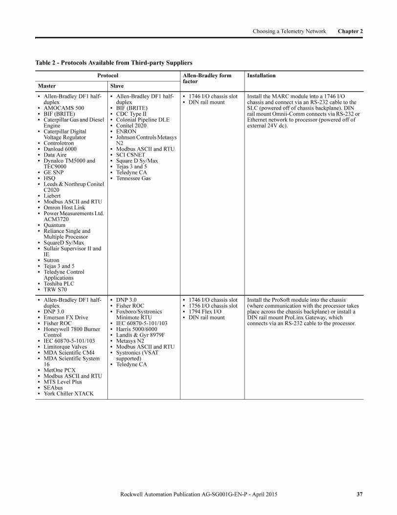
See the following tables for a list of protocols available from third-party suppliers. You can find their addresses and web sites listed in Appendix A. For the most up-to-date list of available protocols, see the supplier’s web page.
36 Rockwell Automation Publication AG-SG001G-EN-P - April 2015
Choosing a Telemetry Network Chapter 2
Table 2 - Protocols Available from Third-party Suppliers
Protocol Allen-Bradley form factor
Installation
Master Slave
• Allen-Bradley DF1 half-duplex
• AMOCAMS 500• BIF (BRITE)• Caterpillar Gas and Diesel
Engine• Caterpillar Digital
Voltage Regulator• Controlotron• Danload 6000• Data Aire• Dynalco TM5000 and
TEC9000• GE SNP• HSQ• Leeds & Northrup Conitel
C2020• Liebert• Modbus ASCII and RTU• Omron Host Link• Power Measurements Ltd.
ACM3720• Quantum• Reliance Single and
Multiple Processor• SquareD Sy/Max• Sullair Supervisor II and
IE• Sutron• Tejas 3 and 5• Teledyne Control
Applications• Toshiba PLC• TRW S70
• Allen-Bradley DF1 half-duplex
• BIF (BRITE)• CDC Type II• Colonial Pipeline DLE• Conitel 2020• ENRON• Johnson Controls Metasys
N2• Modbus ASCII and RTU• SCI CSNET• Square D Sy/Max• Tejas 3 and 5• Teledyne CA• Tennessee Gas
• 1746 I/O chassis slot• DIN rail mount
Install the MARC module into a 1746 I/O chassis and connect via an RS-232 cable to the SLC (powered off of chassis backplane). DIN rail mount Omnii-Comm connects via RS-232 or Ethernet network to processor (powered off of external 24V dc).
• Allen-Bradley DF1 half-duplex
• DNP 3.0• Emerson FX Drive• Fisher ROC• Honeywell 7800 Burner
Control• IEC 60870-5-101/103• Limitorque Valves• MDA Scientific CM4• MDA Scientific System
16• MetOne PCX• Modbus ASCII and RTU• MTS Level Plus• SEAbus• York Chiller XTACK
• DNP 3.0• Fisher ROC• Foxboro/Systronics
Minimote RTU• IEC 60870-5-101/103• Harris 5000/6000• Landis & Gyr 8979F• Metasys N2• Modbus ASCII and RTU• Systronics (VSAT
supported)• Teledyne CA
• 1746 I/O chassis slot• 1756 I/O chassis slot• 1794 Flex I/O• DIN rail mount
Install the ProSoft module into the chassis (where communication with the processor takes place across the chassis backplane) or install a DIN rail mount ProLinx Gateway, which connects via an RS-232 cable to the processor.
Rockwell Automation Publication AG-SG001G-EN-P - April 2015 37

Chapter 2 Choosing a Telemetry Network
Communication Drivers
Rockwell Software also sells communication drivers from KEPware.
KEPServer Enterprise software, a set of communication drivers, which enable OPC connectivity to many third-party devices. Use KEPServer Enterprise software with FactoryTalk View SE software on Windows XP and Windows 2000 systems. KEPServer Enterprise software is catalog number 9301-OPCSRVENE.
The following drivers are available with KEPServer Enterprise software.
Additional KEPServer OPC drivers, such as DNP3, are available directly from Kepware Technologies.
Securing the Telemetry Network
Whenever the telemetry network incorporates links over public networks, consideration must be given to securing the data in the link so that it can't be interpreted, altered or spoofed. An effective way of securing Ethernet data that travels over public networks is to use Virtual Private Network (VPN) technology. VPNs encrypt the Ethernet data before it is transmitted and only the intended receiver knows how to decrypt it. Encompass Partners Secure Crossing and Spectrum Controls supply industrialized VPN devices.
These are some of the tools for securing your SCADA and control system. See page 18 for more information.
Table 3 - Available Drivers with KEPServer Enterprise software
Analog Devices GE SNP Omron FINS Ethernet Thermo Westronics Serial
Aromat GE SNPX Omron FINS Serial TIWAY Host Adapter
Aromat Ethernet Honeywell UDC Omron Host Link Toshiba
Automation Direct EBC IA Super SEL Omron Process Suite Toshiba Ethernet
Automation Direct ECOM IDEC Optimation Optilogic Toyopuc Ethernet PC3/PC2
BUSWARE Ethernet IOTech Pointscan 100 Partlow ASCII Toyopuc Serial
Contrex K Sequence Phillips P8/PC20 Uni-Telway
Contrex M Series Micro-DCI Siemens S5 User Configurable Driver
Cutler-Hammer Mitsubishi A Series Siemens S5 (3964R) Wago Ethernet
DDE Client Driver Mitsubishi Ethernet Siemens S7 MPI Yaskawa Memobus Plus
DIRECT-NET Mitsubishi FX Siemens S7-200 Yokogawa Darwin
EtherTRAK Mitsubishi FX Net Siemens TCP/IP Ethernet Yokogawa Darwin Serial
Fuji Flex Modbus ASCII Serial Simatic 505 Serial Yokogawa DX
GE CCM Modbus Ethernet Simatic 505 Ethernet Yokogawa DX Serial
GE Ethernet Modbus Plus Simulator Yokogawa DXP
GE Ethernet Global Data Modbus Serial SquareD
GE Focas 1 Ethernet Modbus Unsolicited Serial Thermo Westronics Ethernet
38 Rockwell Automation Publication AG-SG001G-EN-P - April 2015

Choosing a Telemetry Network Chapter 2
What To Do Next Record your telemetry network choices on the selection worksheet (page 20). You should have defined the:
• topologies.• transmission modes.• link media.• protocols.
Go to the next chapter to choose your data communication equipment.
Rockwell Automation Publication AG-SG001G-EN-P - April 2015 39

Chapter 2 Choosing a Telemetry Network
Notes:
40 Rockwell Automation Publication AG-SG001G-EN-P - April 2015

Chapter 3
Choosing Data Communication Equipment
Overview Data Communication Equipment (DCE) is the link between a transmission medium and master and remote stations (data terminal equipment or DTE). Data communication equipment includes phone and radio modems as well as microwave and satellite transmission equipment.
Choose the data communication equipment appropriate for the communication media you have chosen.
Master Station
Remote Station Remote Station Remote Station
Topic Page
Choosing a Telephone Modem 42
Choosing a Radio Transmission System 46
Choosing a Satellite Transmission System 53
Choosing Dedicated Wire/Power Line Modems 55
What To Do Next 59
Rockwell Automation Publication AG-SG001G-EN-P - April 2015 41

Chapter 3 Choosing Data Communication Equipment
Choosing a Telephone Modem
Modems convert digital information from a programmable controller or computer to an analog signal that is compatible with the communication media being used. The signal is then transported to the receiving modem, which converts the analog signal back into a digital one.
In the illustration below, digital data from each DTE is converted to an analog signal for transmission over the communication media.
Two modem technology standards exist to make certain that modems developed by different manufactures are compatible.
In most cases, the two modem types are not compatible. Keep this in mind when choosing modems for stations that are being added to or are retrofits for an existing installation. Compatibility charts exist. Consult a modem supplier for more information.
Use the selections that you recorded from the previous section, ‘Choosing a Telemetry Network’, to answer these questions:
• What type of links are you using to transmit data (for example, PSTN, private leased line, or radio)?
• What transmission modes are you using (half-duplex, full-duplex)?
• What are your network topologies (point-to-point, point-to-multipoint)?
• Are you using 2-wire or 4-wire lines?
Once you know the type of modem, use these criteria to help you choose appropriate models:
• Required data communication rate.
DTE DTEDCEDCE
Type Description
Bell The Bell standard was the predominant standard in the United States until the break-up of AT&T in the USA.
Consultive Committee for International Telephone and Telegraph (CCITT)
The CCITT standard is the international standard that is now becoming the standard for the USA. Most modems now conform to one or more of the CCITT standards, such as V.32, V.32bis, and V.22.
42 Rockwell Automation Publication AG-SG001G-EN-P - April 2015

Choosing Data Communication Equipment Chapter 3
• Requirements of the DTE devices to which you are connecting.
– Do you need asynchronous or synchronous operation?
– What interfaces do you need (RS-232, MIL 188, EIA-449, IEEE 488, CCITT V.24)?
– What other features are required to support your DTEs?
• Required standards (for example, UL, CSA, and FCC).
• Space requirements. Do you need a rack-mounted or stand-alone modem?
• Input-power requirements.
• Ambient temperature specifications.
• Modem design and operation.
• Modem response time.
Once you have a good idea of the modem type you need, choose a modem based on the many available features and options, which vary by manufacturer.
Analog Dial-up Modem
The following table lists the modem features that are required by certain Allen-Bradley DTE devices. Since you may not know the exact programmable controller or computer your application requires, you may need to refer to this table after you have chosen your DTEs to finalize your modem selection.
TIP If you are using all Allen-Bradley DTE devices,
choose an asynchronous modem.
Topic Page
Analog Dial-up Modem 43
Analog Leased-line Modems 44
Digital Leased-line ISUs 45
% %
If you are using this DTE The DTE needs support for Make certain the modem you choose has this feature
ControlLogix processors ASCII strings to configure and control the dial-up modem
AT-command-set support
CompactLogix
MicroLogix (except 1000)
SLC 5/03, 5/04, and 5/05 processors
RSLinx software
MicroLogix 1000 controllers Answer capability only Auto answer support
Rockwell Automation Publication AG-SG001G-EN-P - April 2015 43

Chapter 3 Choosing Data Communication Equipment
Consult the vendor for information about their product offerings.
Analog Leased-line Modems
Depending on the speed of the modem you choose, you may need a better conditioned line. A leased-line modem's cost is composed of two principal items:
• Monthly leased-line charges, which are directly proportional to the conditioning or communication rate capability of the leased line
• Modem price, which is directly proportional to the modem's communication rate capability
Therefore, the most efficient system matches the maximum communication rate of the modem to that of the leased line to which the modems are attached.
For Point-to point, Full-duplex Applications
Choose an asynchronous, full-duplex 2-wire or 4-wire leased-line modem pair.
For Point-to-multipoint, Half-duplex Applications
Choose a modem which supports asynchronous, point-to-multipoint operation over a 4-wire or 2-wire leased line. Typically these modems have a ‘master’ setting for the modem connected to the master station and a ‘slave’ setting for the modems that connect to remote stations.
For the master station, choose a modem that has the capability of holding the modem carrier high so that no time is lost waiting for the modem carrier to turn on and stabilize whenever the ‘master’ modem has data to transmit.
For the remote stations, choose a modem that can switch the carrier on and off, whether transmitting or receiving, based on RTS/CTS signal handshaking with the other remote stations. You need to use a switched modem carrier since the stations share the same leased-line channel and would jam each other's data transmission attempts if two or more remote station modems set their carriers high at the same time. Using a half-duplex mode virtually guarantees that no two remote stations will attempt to transmit data at the same time.
Supplier Maximum Transmission Rate
Modem Model
DATA-LINC Group 33600/28800 DLM4000/DLM4500
Miille Applied Research Co. Inc.
2400 166-100 (1746 chassis mount)
2400, 14400, 28800, and 33600
366-100 (DIN rain mount)
Rockwell Automation 28800 9300-RADKIT
28800 9300-RADES(1)
(1) Ethernet dial-up modem
Phone Company
PLL PLL
44 Rockwell Automation Publication AG-SG001G-EN-P - April 2015
Choosing Data Communication Equipment Chapter 3
Whether an application uses 2-wire or 4-wire leased lines, choose remote modems that support switched modem carriers.
Modem Suppliers
See the following table for a listing of recommended analog leased-line modem suppliers and respective modem models. Consult the vendor for information about their product offerings.
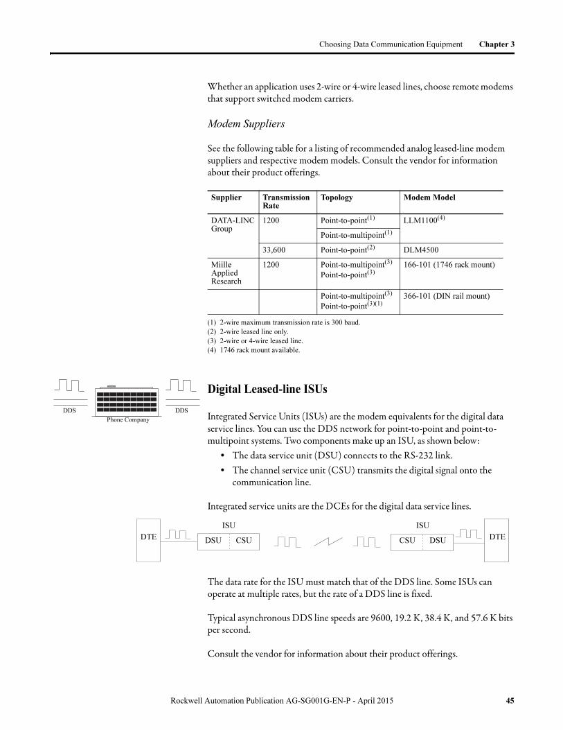
Digital Leased-line ISUs
Integrated Service Units (ISUs) are the modem equivalents for the digital data service lines. You can use the DDS network for point-to-point and point-to-multipoint systems. Two components make up an ISU, as shown below:
• The data service unit (DSU) connects to the RS-232 link.• The channel service unit (CSU) transmits the digital signal onto the
communication line.
Integrated service units are the DCEs for the digital data service lines.
The data rate for the ISU must match that of the DDS line. Some ISUs can operate at multiple rates, but the rate of a DDS line is fixed.
Typical asynchronous DDS line speeds are 9600, 19.2 K, 38.4 K, and 57.6 K bits per second.
Consult the vendor for information about their product offerings.
Supplier Transmission Rate
Topology Modem Model
DATA-LINC Group
1200 Point-to-point(1)
(1) 2-wire maximum transmission rate is 300 baud.
LLM1100(4)
(4) 1746 rack mount available.
Point-to-multipoint(1)
33,600 Point-to-point(2)
(2) 2-wire leased line only.
DLM4500
Miille Applied Research
1200 Point-to-multipoint(3)
Point-to-point(3)
(3) 2-wire or 4-wire leased line.
166-101 (1746 rack mount)
Point-to-multipoint(3)
Point-to-point(3)(1)366-101 (DIN rail mount)
Phone Company
DDS DDS
DTE DSU CSU
ISU
CSU DSU
ISU
DTE
Rockwell Automation Publication AG-SG001G-EN-P - April 2015 45
Chapter 3 Choosing Data Communication Equipment
Telephone Modem and ISU Installation Guidelines
Telephone modems and ISUs require a telephone-company approved connector. Consult your modem/ISU vendor for installation requirements.
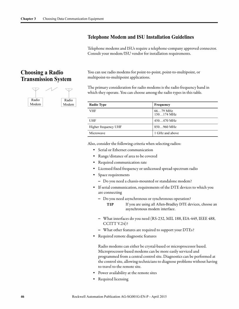
Choosing a Radio Transmission System
You can use radio modems for point-to-point, point-to-multipoint, or multipoint-to-multipoint applications.
The primary consideration for radio modems is the radio frequency band in which they operate. You can choose among the radio types in this table.
Also, consider the following criteria when selecting radios:• Serial or Ethernet communication• Range/distance of area to be covered• Required communication rate• Licensed fixed frequency or unlicensed spread-spectrum radio• Space requirements
– Do you need a chassis-mounted or standalone modem?• If serial communication, requirements of the DTE devices to which you
are connecting– Do you need asynchronous or synchronous operation?
– What interfaces do you need (RS-232, MIL 188, EIA-449, IEEE 488, CCITT V.24)?
– What other features are required to support your DTEs?• Required remote diagnostic features
Radio modems can either be crystal-based or microprocessor based. Microprocessor-based modems can be more easily serviced and programmed from a central control site. Diagnostics can be performed at the control site, allowing technicians to diagnose problems without having to travel to the remote site.
• Power availability at the remote sites• Required licensing
Radio Type Frequency
VHF 66…79 MHz150…174 MHz
UHF 450…470 MHz
Higher frequency UHF 850…960 MHz
Microwave 1 GHz and above
TIP If you are using all Allen-Bradley DTE devices, choose an
asynchronous modem interface.
Radio
Modem
Radio
Modem
46 Rockwell Automation Publication AG-SG001G-EN-P - April 2015

Choosing Data Communication Equipment Chapter 3
• Required standards (for example, UL, CSA, or FCC)• Whether the radio modem is composed of an integrated unit or a radio
and a modem as separate units• Radio modem design and operation• Data security• Required response time• Ability to buffer serial data and avoid data collisions between radio
modems to allow Report-by-Exception• Ability to route DF1 data packets and to store and forward
Licensing
There are two major types of radio networks; licensed narrow-band fixed-frequency radio and unlicensed spread-spectrum radio.
Licensed Fixed-frequency Radio
Licensed narrow-band fixed-frequency radio operate in the UHF/VHF bands.
The FCC requires that you obtain a license before you operate a radio modem at a particular location and frequency within these radio frequency bands.
Unlicensed Spread-spectrum Radio
Alternatively, the FCC allows you to use relatively low transmit power, spread-spectrum radio modems without a license.
Spread-spectrum radio systems operate in the 900MHz and the 2.4/4.8 industrial, scientific, and medical (ISM) bands.
There are two implementations of spread-spectrum currently in use:
Direct-sequence spread-spectrum (DSSS) radio takes the same data that would be transmitted on a single narrowband fixed frequency and transmits it over an available wideband of frequencies at a reduced power level.
Frequency-hopping spread-spectrum (FHSS) radio also takes the same data that would be transmitted on a single narrowband fixed frequency, but in this case transmits it over a sequence of narrowband frequencies over the available wideband. That is, it 'hops' from one narrowband frequency to the next.
Rockwell Automation Publication AG-SG001G-EN-P - April 2015 47

Chapter 3 Choosing Data Communication Equipment
Licensed Fixed-frequency vs Unlicensed Spread-spectrum
Considerations
Consider the following when choosing either a licensed fixed-frequency or an unlicensed spread-spectrum system:
• The licensed fixed-frequency option requires a license - this can be an issue in urban areas where available frequencies are already allocated.
However, in recent years the FCC has subdivided the existing licensed frequency bands to make more available. Also, many former users of these licensed frequency bands have switched to newer technologies such as cellular, freeing up more bands for new potential licensees.
The unlicensed spread-spectrum option does not require a license, but this does mean that there is the potential for other users to encroach on the frequencies being used. However, this is rarely an issue due to the lower power levels and technologies used with spread-spectrum radio.
• Licensed fixed-frequency systems are allowed to transmit at higher power levels than spread-spectrum systems (5 watts vs 1 watt) and thus have greater range capability, are less prone to attenuation from atmospheric and environmental conditions, and have less need for line of sight configurations.
• Licensed fixed-frequency systems transmit at lower frequencies than spread-spectrum systems and thus have greater range capability, are less prone to attenuation from atmospheric and environmental conditions, and have less need for line of sight configurations.
• Licensed fixed-frequency systems typically support lower bandwidth throughputs than spread-spectrum systems (due to smaller channel widths). However, this is often not an issue for industrial applications using small packet sized serial protocols.
• Licensed fixed-frequency systems can be more susceptible to noise or interference as they utilize a single frequency.
Spread-spectrum Direct-sequence vs Frequency-hopping
Considerations
• Spread-spectrum direct-sequence systems typically support higher data throughputs because of the data transmission being spread over a wider band. They can be susceptible to noise that occurs over the wideband being used.
• Frequency-hopping systems support a lower data throughput but have greater noise immunity because the frequency at which the transmission takes place is constantly changing.
48 Rockwell Automation Publication AG-SG001G-EN-P - April 2015
Choosing Data Communication Equipment Chapter 3
Radio Modem Types
There are two types of radio modems: Ethernet modems and Serial modems.
Ethernet Radio Modems
Ethernet radio modems have a standard IEEE 802.3 (10Base-T or 100BaseT) interface that can connect directly to the Ethernet port on the computer or PLC, or to the Ethernet network via a bridge or router.
Serial Radio Modems
Serial modems may be sold as:
• integrated units.
– Key-up time between the radio and modem is integrated fully. The unit does not require programmable controller intervention.
– When the modem and transmitter/receiver are separate, compatibility becomes an issue.
• two separate units.
– a digital data modem that has an RS-232 connector– a radio transmitter/receiver that has an antenna connector
Often, since the modem is not able to directly control when the radio transmits a carrier, the data communication device must also have a way to key-up the radio transmitter just prior to transmitting data to the modem.
Also, consider the time-to-transmit power requirements of the combination, since the external modem is not able to determine when the radio is at full power. The modem requires a time delay prior to data transmission.
Like leased-line modems, the cost of radio modems is directly proportional to the communication rate or communication throughput that they can support.
Select your modem based on the type of application: point-to-point full-duplex, point-to-multipoint half-duplex, or multipoint-to-multipoint full-duplex.
For Point-to-point Full-duplex Applications
Choose full-duplex radios. This application requires a separate transmitter and receiver in each radio modem.
Rockwell Automation Publication AG-SG001G-EN-P - April 2015 49
Chapter 3 Choosing Data Communication Equipment
For Point-to-multipoint (or Broadcast) Half-duplex Applications
Choose full-duplex master radio, half-duplex master radio, or half-duplex remote radios.
For best performance use a ‘master’ radio modem capable of full-duplex operation, since a full-duplex radio modem has a transmitter that is separate from the receiver. This provides shorter RTS-to-CTS delays with each master station data transmission.
To be cost-efficient, use radio modems that have a transceiver for the remote stations. Having a transceiver limits modems to only half-duplex operation, since they can only send or receive data at one time. Therefore, with each remote station transmission, the RTS-to-CTS delay is longer, since the transceiver takes time to switch from receiver operation to transmitter operation. This time delay allows the transmitter time to fully power up.
Also, think about setting up your master station in a redundant configuration. If the master station's radio modem goes down, the whole communication system is down. Whereas, when a remote station radio modem goes down, only communication to a single remote station is lost.
For Multipoint-to-multipoint, Full-duplex Applications
Choose ‘intelligent’ radios. Although ‘intelligent’ radio modems receive and transmit across the airwaves in a half-duplex fashion, they are able to transfer data with the attached controller in full-duplex fashion when the controller is configured to communicate using DF1 radio modem protocol. This allows any station to trigger a message instruction in ladder logic and immediately transmit it to the attached radio modem. The radio modem buffers the message and transmits it once it has an idle channel available.
50 Rockwell Automation Publication AG-SG001G-EN-P - April 2015
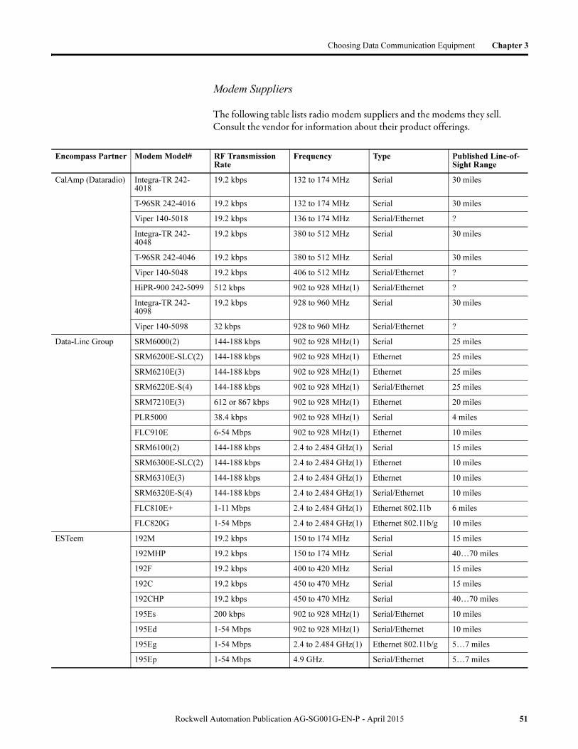
Choosing Data Communication Equipment Chapter 3
Modem Suppliers
The following table lists radio modem suppliers and the modems they sell. Consult the vendor for information about their product offerings.
Encompass Partner Modem Model# RF Transmission Rate
Frequency Type Published Line-of-Sight Range
CalAmp (Dataradio) Integra-TR 242-4018
19.2 kbps 132 to 174 MHz Serial 30 miles
T-96SR 242-4016 19.2 kbps 132 to 174 MHz Serial 30 miles
Viper 140-5018 19.2 kbps 136 to 174 MHz Serial/Ethernet ?
Integra-TR 242-4048
19.2 kbps 380 to 512 MHz Serial 30 miles
T-96SR 242-4046 19.2 kbps 380 to 512 MHz Serial 30 miles
Viper 140-5048 19.2 kbps 406 to 512 MHz Serial/Ethernet ?
HiPR-900 242-5099 512 kbps 902 to 928 MHz(1) Serial/Ethernet ?
Integra-TR 242-4098
19.2 kbps 928 to 960 MHz Serial 30 miles
Viper 140-5098 32 kbps 928 to 960 MHz Serial/Ethernet ?
Data-Linc Group SRM6000(2) 144-188 kbps 902 to 928 MHz(1) Serial 25 miles
SRM6200E-SLC(2) 144-188 kbps 902 to 928 MHz(1) Ethernet 25 miles
SRM6210E(3) 144-188 kbps 902 to 928 MHz(1) Ethernet 25 miles
SRM6220E-S(4) 144-188 kbps 902 to 928 MHz(1) Serial/Ethernet 25 miles
SRM7210E(3) 612 or 867 kbps 902 to 928 MHz(1) Ethernet 20 miles
PLR5000 38.4 kbps 902 to 928 MHz(1) Serial 4 miles
FLC910E 6-54 Mbps 902 to 928 MHz(1) Ethernet 10 miles
SRM6100(2) 144-188 kbps 2.4 to 2.484 GHz(1) Serial 15 miles
SRM6300E-SLC(2) 144-188 kbps 2.4 to 2.484 GHz(1) Ethernet 10 miles
SRM6310E(3) 144-188 kbps 2.4 to 2.484 GHz(1) Ethernet 10 miles
SRM6320E-S(4) 144-188 kbps 2.4 to 2.484 GHz(1) Serial/Ethernet 10 miles
FLC810E+ 1-11 Mbps 2.4 to 2.484 GHz(1) Ethernet 802.11b 6 miles
FLC820G 1-54 Mbps 2.4 to 2.484 GHz(1) Ethernet 802.11b/g 10 miles
ESTeem 192M 19.2 kbps 150 to 174 MHz Serial 15 miles
192MHP 19.2 kbps 150 to 174 MHz Serial 40…70 miles
192F 19.2 kbps 400 to 420 MHz Serial 15 miles
192C 19.2 kbps 450 to 470 MHz Serial 15 miles
192CHP 19.2 kbps 450 to 470 MHz Serial 40…70 miles
195Es 200 kbps 902 to 928 MHz(1) Serial/Ethernet 10 miles
195Ed 1-54 Mbps 902 to 928 MHz(1) Serial/Ethernet 10 miles
195Eg 1-54 Mbps 2.4 to 2.484 GHz(1) Ethernet 802.11b/g 5…7 miles
195Ep 1-54 Mbps 4.9 GHz. Serial/Ethernet 5…7 miles
Rockwell Automation Publication AG-SG001G-EN-P - April 2015 51

Chapter 3 Choosing Data Communication Equipment
Ethernet vs. Serial Radio Modem Considerations
• Ethernet offers the advantage of widespread acceptance and connectivity and easier implementation.
• Ethernet ports are available on a wide variety of commercial and industrial devices such as personal computers and programmable logic controllers. Serial ports are becoming less common on both, particularly on commercial devices, and may not be available without the use of an external adapter.
• Serial may be required in applications where Ethernet is not available for the devices already installed or to be added to the network.
• Ethernet allows connection to the Internet (for example, remote access and email/text notifications).
• Ethernet supports multiple applications on the same network (for example, web servers, video cameras, and data collection from multi-vendor/protocol devices).
FreeWave Technologies
LRS-455 19.2 kbps 435 to 470 MHz. Serial 60 miles
LRS-760 38.4 kbps 757 to 788 MHz. Serial 30 miles
FGR2-CE-U 115.2 or 153.6 kbps 902 to 928 MHz(1) Serial 60 miles
HTPlus 867 kbps 902 to 928 MHz(1) Ethernet 15 miles
FGRplus RE 154 kbps 902 to 928 MHz(1) Ethernet 60 miles
LRS-140 19.2 kbps 1.427 to 1.432 GHz. Serial 30 miles
IM-800X009 115.2 kbps 2.4 to 2.484 GHz(1) Serial 20 miles
ProSoft Technology RLX-FHE 250 kbps 2.4 to 2.484 GHz(1) Ethernet 15 miles
RLX-FHES 250 kbps 2.4 to 2.484 GHz(1) Serial/Ethernet 15 miles
RLX-FHS 250 kbps 2.4 to 2.484 GHz(1) Serial 15 miles
RLX-IFH9E 1.1 Mbps or 345 kbps
902 to 928 MHz(1) Ethernet 30 miles
RLX-IFH24E 1.1 Mbps or 345 kbps
2.4 to 2.484 GHz(1) Ethernet 15 miles
RLX-IFH9S 230, 172, 115 or 19.2 kbps
902 to 928 MHz(1) Serial 30 miles
RLX-IFH24S 230, 172, 115 or 19.2 kbps
2.4 to 2.484 GHz(1) Serial 15 miles
RLXIB-IHA 6-54 Mbps 5.725 to 5.850 GHz Ethernet 802.11a 5 miles
RLXIB-IHG 1-54 Mbps 2.4 to 2.484 GHz(1) Ethernet 802.11b/g 10 miles
RLXIB-IHW 1-54 Mbps 5.725 to 5.850 GHz Ethernet 802.11a/b/g 3 miles
RLXIB-IHW-66 1-54 Mbps 5.725 to 5.850 GHz Ethernet 802.11a/b/g 3 miles
RLXIB-IESC 1-54 Mbps 5.725 to 5.850 GHz Serial/Ethernet 802.11a/b/g
3 miles
RLX-IH 1-11 Mbps 2.4 to 2.484 GHz(1) Ethernet 802.11b 20 miles
Encompass Partner Modem Model# RF Transmission Rate
Frequency Type Published Line-of-Sight Range
52 Rockwell Automation Publication AG-SG001G-EN-P - April 2015

Choosing Data Communication Equipment Chapter 3
• Ethernet supports higher transmission speeds. However, consider that this may be offset by the fact that Ethernet is usually less efficient in transmitting industrial data than serial protocols. This is because industrial data typically consists of smaller packets (for example, control information) than commercial data (for example, file downloads). The overhead of an Ethernet packet is usually much greater than that of a typical serial packet.
• Ethernet radio modems typically operate in higher, spread-spectrum/unlicensed frequency bands (900Mhz, 2.4/5.8 GHz) that are limited in allowable output power and thus have less range than traditional licensed fixed frequency serial radio modems.
Radio Modem Installation Guidelines
For a radio system, you need these components.
When becoming involved with radio system design, consult radio system vendors. A site survey should always be performed to determine the following:
• Radio transmit power requirements • Quantity of radios• Whether or not repeaters are needed• Antenna type and heights
Choosing a SatelliteTransmission System
A Very Small Aperture Terminal (VSAT) network provides a mechanism for multiple remote sites to communicate with a central site (a hub) on a shared access basis. You can choose between single-hop and double-hop systems.
Single-Hop
Data is transmitted across leased lines to the master Earth station, which beams the data to the satellite. The satellite beams the data to the remote sites (or master site).
The charges may be high if you purchase your own inbound and outbound channels, and usually, you do not use the channels' entire bandwidth. Also, you must pay for the leased line that transports the data to the master hub.
Component Comments
Antennas The height and quality depend upon the application and project budget.
Cabinets Consider the environmental conditions or the location of the remote sites to select an appropriate cabinet.
Repeaters(optional)
If the radios are not located in a line of sight with each other (for example, due to terrain), you may need repeaters to carry the signal from the initiating station to the destination station.
Earth
Rockwell Automation Publication AG-SG001G-EN-P - April 2015 53

Chapter 3 Choosing Data Communication Equipment
You can choose a single-hop system that shares the inbound and outbound channels with others to offset costs.
Double-hop
A VSAT site is directly connected to your master or remote station. This VSAT beams the data to the satellite, which beams the data to either the remote site or master site.
With a double-hop system, you are not dependent upon the availability of terrestrial leased lines.
These components make up a satellite transmission system:
Power Amplifier (transmit)/low
Noise Amplifier (receive)
Up/down Converter
Master Station
Demodulator B
Demodulator A
Modulator
AntennaAntennaUp/down Converter
Satellite ModemSatellite Modem
A
Satellite Modem
A
Up/down Converter
Remote
Remote
Power Amplifier (transmit)/low
Noise Amplifier (receive)
54 Rockwell Automation Publication AG-SG001G-EN-P - April 2015

Choosing Data Communication Equipment Chapter 3
Choosing Dedicated Wire/Power Line Modems
You can easily integrate dedicated wire/power line modems into your application. You need a suitable dedicated wire pair or power line and an RS-232 interface.
The following table lists the recommended dedicated wire/power line modem supplier and modem models. Consult the vendor for installation requirements and detailed information about their product offerings.
Choosing a Cellular Transmission System
Cellular modems are increasingly being used in SCADA applications to increase productivity and uptimes. One of the key benefits of the cellular modem over WLAN modems is that cellular modems are able to offer more network coverage mobility. Being able to collect and distribute data without the limitation of wireless hotspots or having a dedicated wired network using cellular network is powerful. Typically a cellular modem is used when the network coverage requirement is large and when use of satellites or other technology is not cost effective. Cellular networks are predominantly offered as major technologies namely, GSM (Global System for Mobile Communications) and CDMA (Code Division Multiple Access). The GSM technology is more popular across different countries while the CDMA is more popular in the U.S.
Cellular Network Architecture
The diagram below shows a typical cellular network layout.
Supplier Transmission Rate Topology Modem Model
DATA-LINC Group
9600 bps Point-to-pointPoint-to-multipoint
MDL500(1)
(1) suitable for power line installations.
1200 bps Point-to-pointPoint-to-multipoint
LLM1100
19200 bps Point-to-point DLM4000
Remote Site
Remote LAN/Devices
Gateway Mobile Interface
gets IP address
from Cellular
Cellular IP
Network
Host Site (HQ)
Customer
WAN or
Rockwell Automation Publication AG-SG001G-EN-P - April 2015 55

Chapter 3 Choosing Data Communication Equipment
Two major components of the cellular network are the remote site and the host or central site. The remote site has application devices locally networked and communicate to the host site by using the cellular network through a gateway. These devices could be a PLC or other equipment like an embedded computer. The host site runs an application server that could be a web server that is responsible for running the application.
Depending on the application of the cellular network, a cellular network may be organized as Mobile Originated mode, Mobile Terminated mode, or Both Mobile Originated and Terminated mode.
In the Mobile Originated mode, the remote device or node initiates a connection. This connection is terminated at the host, usually at the host web server. In the Mobile Terminated mode, a host will request or poll for information from the remote device. In this case, the host device initiates the connection and the connection is terminated at the remote site. In the Both Mobile Originated and Terminated mode, the host and the remote site are able to initiate connections. Usually, the host will poll for information from the remote site, but the remote site is also proactively able to send out event and alarm information to the host site.
To use the cellular modem technology effectively, a user has to have the following components:
• Data plan subscription • Cellular modem
The user needs to make sure that the cellular modem purchased for the network is compatible with a good cellular service provider's plan. As mentioned above, there are two very popular cellular technology types namely GSM and CDMA. Verizon Wireless, Alltel, and Sprint use CDMA. T-Mobile and AT&T use the GSM cellular format. Often, CDMA may be referred to as or associated with W-CDMA, EV-DO, and EV-DV, while GSM/GPRS may be associated with EDGE or EGPRS.
Below are some considerations to be made before finalizing a cellular modem and plan purchase:
• Ensure that the manufacturer of the cellular modem device offers technical support and other regular update services.
• If you are expecting certain areas to have low connectivity issues, purchase a signal booster or repeaters to enhance data reception.
• Understand the different cellular providers' plan options in the target areas.
• Choose a carrier that offers the maximum reception coverage in the target areas. Most carriers have interactive websites with geographic maps that you can use to determine coverage in your area.
Some cellular modem providers have dedicated contacts with the cellular providers who can facilitate and make cellular account set up easier.
56 Rockwell Automation Publication AG-SG001G-EN-P - April 2015
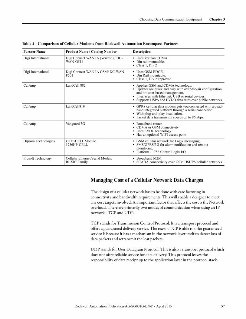
Choosing Data Communication Equipment Chapter 3
Managing Cost of a Cellular Network Data Charges
The design of a cellular network has to be done with care factoring in connectivity and bandwidth requirements. This will enable a designer to meet any cost targets involved. An important factor that affects the cost is the Network overhead. There are primarily two modes of communication when using an IP network - TCP and UDP.
TCP stands for Transmission Control Protocol. It is a transport protocol and offers a guaranteed delivery service. The reason TCP is able to offer guaranteed service is because it has a mechanism in the network layer itself to detect loss of data packets and retransmit the lost packets.
UDP stands for User Datagram Protocol. This is also a transport protocol which does not offer reliable service for data delivery. This protocol leaves the responsibility of data receipt up to the application layer in the protocol stack.
Table 4 - Comparison of Cellular Modems from Rockwell Automation Encompass Partners
Partner Name Product Name / Catalog Number Description
Digi International Digi Connect WAN IA (Verizon) / DC-WAN-G511
• Uses Verizon CDMA. • Din rail mountable.• Class 1, Div 2
Digi International Digi Connect WAN IA GSM/ DC-WAN-F501
• Uses GSM EDGE. • Din Rail mountable.• Class 1, Div 2 approved.
CalAmp LandCell 882 • Applies GSM and CDMA technology.• Updates are quick and easy with over-the-air configuration
and browser-based management.• Interfaces with Ethernet, USB or serial devices.• Supports HSPA and EVDO data rates over public networks.
CalAmp LandCell819 • GPRS cellular data modem gets you connected with a quad-band integrated platform through a serial connection.
• With plug-and-play installation.• Packet data transmission speeds up to 86 kbps.
CalAmp Vanguard 3G • Broadband router• CDMA or GSM connectivity• Uses EVDO technology• Has an optional WIFI access point
Hiprom Technologies GSM /CELL Module 1756HP-CELL
• GSM cellular network for Logix messaging.• SMS/GPRS/3G for alarm notification and remote
monitoring.• Platform - 1756 ControlLogix I/O
Prosoft Technology Cellular Ethernet/Serial ModemRLXIC Family
• Broadband M2M. • SCADA connectivity over GSM HSUPA cellular networks.
Rockwell Automation Publication AG-SG001G-EN-P - April 2015 57

Chapter 3 Choosing Data Communication Equipment
While it may seem that using the TCP mechanism should be the obvious choice, this is not always true. TCP gives room to a lot of network overhead as it initiates packet retransmissions and Acknowledgement packets whenever it detect a loss in data receipt. Several applications employ their own data delivery integrity validation procedures and do not require the network to validate data delivery for it. In this case, the use of UDP may be encouraged as UDP has much less network overhead compared to TCP. Hence, a choice of transport protocol to use to needs to be made based on the application. A good choice of protocol can prove to be cost beneficial.
Determining Monthly Cost for Data Usage
Monthly Circuit Switch data cost consists of a fixed data rate charge for a certain amount of data per month, with additional data typically costing about US$0.05/Megabyte. Roaming data charges are applicable if the equipment is used outside the coverage area.
Monthly Packet data cost is charged to the nearest Kilobyte transferred. Cellular providers have different plans (which could range from a set minimum to an ‘unlimited’ maximum); each consisting of a minimum block of Kilobytes. If the monthly Kilobytes transferred figure is exceeded, the balance is billed as extra charges. Site costs typically range from US$30…70 per month (including the Kilobyte transfer).
Below is an example from a Rockwell Automation Encompass Partner, Prosoft who is cellular modem provider.
Prosoft offers their modems bundled with data service plans from AT&T and Verizon. Once a user selects a preferred carrier, Prosoft provides pricing and other order related information. The list price for a Prosoft cellular modem device with a two year service contract is approximately US$575. The Data Service charge for the period of two years is an additional US$900 with a US$100 activation fee.
Prosoft also provides a plan where you can buy an already activated modem. This plan costs about US$575 for the modem with a $100 Monthly ‘Try Before You Buy’ Prosoft Data service plan. The customer is also charged a two year data service plan with a two year activation plan. But, if the customer decides to return the modem, Prosoft accepts the device back without a restocking fee and will not invoice the Data Service plan and Activation charge. The trial period permitted is 60 days.
Other providers have similar products and services as well that can be used when setting up a cellular network.
58 Rockwell Automation Publication AG-SG001G-EN-P - April 2015

Choosing Data Communication Equipment Chapter 3
Advantages and Disadvantages over other Modem
Technologies
Listed are the advantages and disadvantages of choosing a cellular transmission system over other modem technologies.
Advantages
• Ability to use existing secure cellular infrastructure thereby significantly reducing cost of cabling and antenna towers.
• Increases mobility of users. • The network coverage area can be made significantly larger when using
cellular networks as networks can be setup in areas where wiring may not be possible.
Disadvantages
• Dependency on a third party supplier for service and support of communication infrastructure.
• Since you pay based on the amount of data transmitted, it becomes important to minimize (or at least monitor) the amount and frequency of data transmission to avoid large overage charges.
• There could be situations in which cellular network coverage is not available in international geographic locations as it is in the North American regions. In those cases, a user needs to rely completely on the coverage provided by the local cellular service provider.
What To Do Next Choose your data communication equipment. You may need more specific information about the control devices to which you are connecting. Therefore, after choosing your master and remote stations, refer to this section as needed to finalize your transmission system.
Go to the next chapter to choose master stations.
Rockwell Automation Publication AG-SG001G-EN-P - April 2015 59

Chapter 3 Choosing Data Communication Equipment
Notes:
60 Rockwell Automation Publication AG-SG001G-EN-P - April 2015

Chapter 4
Choosing a Device for a Master Station
Overview
The master station in a SCADA system does the following: • Gets field data by periodically reading and/or receiving data directly from
the remote stations or through a submaster• Provides coordinated monitoring and control over the entire system
through its operator interface
Several master station types are possible.
Figure 5 - Available Master Station Types
Topic Page
Choosing a Computer-based Master Station 63
Choosing a Programmable Controller-based Master Station 65
Choosing a Data-concentrating Submaster Station 66
Choosing a Data-routing Submaster Station 67
Needed Equipment 69
Installation Guidelines 69
What To Do Next 69
remote stations
remote stations
remote stations
DH+™, Ethernet or ControlNetRS-232 linksIn small SCADA systems, a single
personal computer can serve as
both the master station and central
computer.
Use a programmable controller as a
master station if an application
requires one or more master stations
separate from the operator interface,
such as when you need to control
local inputs and outputs.
Computer-based Master PLC-based Master
Ethernet
Remote Stations
Remote Stations
Remote Stations
Serial or Ethernet
FactoryTalk View SE
Software with DNP3
OPC Driver
Serial or Ethernet
Rockwell Automation Publication AG-SG001G-EN-P - April 2015 61
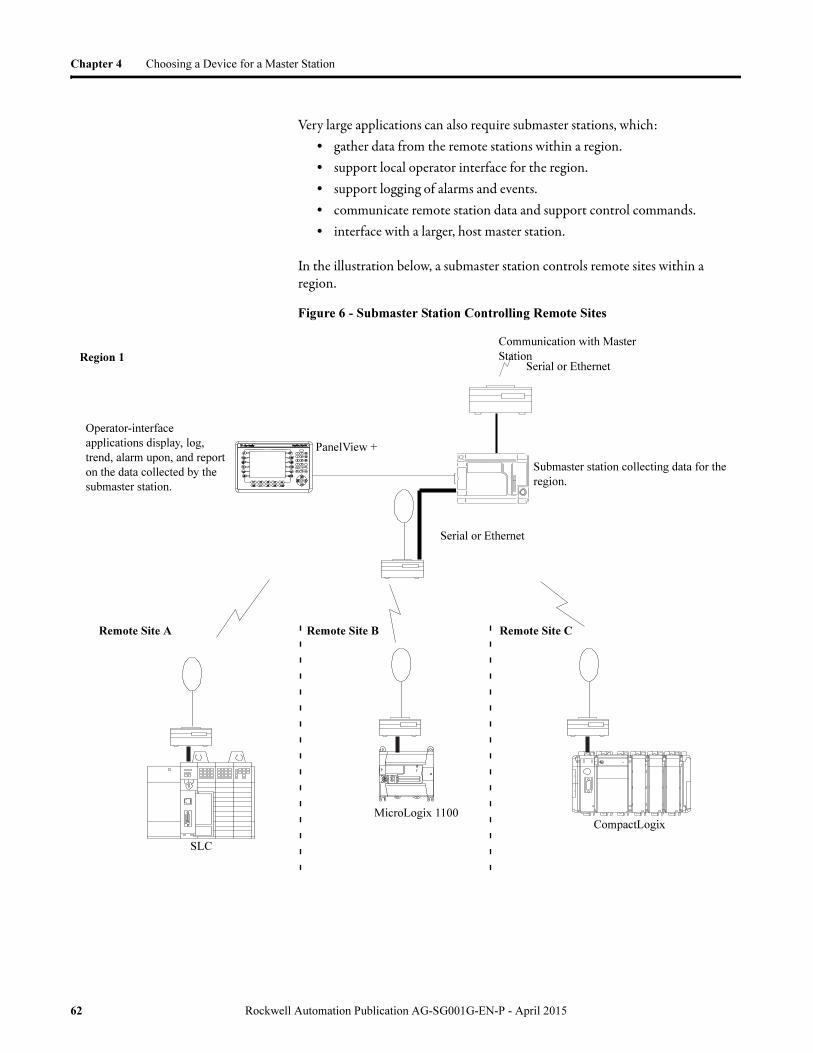
Chapter 4 Choosing a Device for a Master Station
Very large applications can also require submaster stations, which:• gather data from the remote stations within a region.• support local operator interface for the region.• support logging of alarms and events.• communicate remote station data and support control commands.• interface with a larger, host master station.
In the illustration below, a submaster station controls remote sites within a region.
Figure 6 - Submaster Station Controlling Remote Sites
Submaster station collecting data for the
region.
Operator-interface
applications display, log,
trend, alarm upon, and report
on the data collected by the
submaster station.
Communication with Master
StationRegion 1
PanelView +
Remote Site A Remote Site B Remote Site C
MicroLogix 1100CompactLogix
SLC
Serial or Ethernet
Serial or Ethernet
62 Rockwell Automation Publication AG-SG001G-EN-P - April 2015

Choosing a Device for a Master Station Chapter 4
Choosing a Computer-based Master Station
For many small SCADA configurations, a personal computer running Rockwell Software FactoryTalk View SE software and DNP3 OPC Driver can meet the requirements for both the operator interface and the master station. FactoryTalk View SE software provides not only an operator interface but also master station functionality, both at the same time. This configuration provides for the most integrated and cost-effective master station for smaller applications.
Using FactoryTalk View SE Software as a Master Station
A single FactoryTalk View SE workstation can simultaneously be:• the host computer, running operator-interface software.• the master station, performing the remote station
data-gathering functions.• the remote station programming terminal.
To create a cost-effective solution, equip a workstation with the following:• FactoryTalk View SE HMI software• DNP3 OPC server software• RSLogix programming software
l
l
l
FactoryTalk View SE Software with DNP3 OPC
Driver
Remote Stations
Remote Stations
Station Connected via Point-to-point Link
Full-duplex Protocol
orData Sharing
Ethernet
Serial or Ethernet
Rockwell Automation Publication AG-SG001G-EN-P - April 2015 63

Chapter 4 Choosing a Device for a Master Station
Using FactoryTalk View SE Software as a Plant HMI
Minimum requirements:• Personal computer with Windows XP or later operating system• Ethernet communication card• Cables• FactoryTalk View SE software• RSLinx communication server software• For the PLC-based master station requirements, see Choosing a
Programmable Controller-based Master Station
Ethernet
Ethernet Based
Master Station
Remote Station(s)
Redundant Servers
Serial or Ethernet
64 Rockwell Automation Publication AG-SG001G-EN-P - April 2015

Choosing a Device for a Master Station Chapter 4
Choosing a ProgrammableController-basedMaster Station
Choose a programmable controller-based master station if any of these requirements exists:
• The master station must be able to control local I/O.• Your application requires master station redundancy.• More robust and flexible PLC hardware platform for polling remotes.
Use this chart to help you choose a programmable controller master station.
Controller MicroLogix SLC
CompactLogix Control-Logix
Specification 1100
1400 5/05 L23E
L4x
L32E
L35E
Number of RS-232 comms channels
1 1 1 1 1 1 1 1
Integral DF1 full-duplex
? ? ? ? ? ? ? ?
Integral DF1 half-duplex master
?(2)
(2) Series C, FRN 7 or later.
?(3)
? ? ? ? ? ?
Integral DF1 radio modem
?(2)
?(3)
?(5)
(5) Series C, FRN 6 or later.
? ? ? ? ?
Integral/backplane modbus RTU master(1)
(1) Standalone DF1 full-duplex to Modbus interfaces are available from ProSoft Technology and
Miille Applied Research Company.
?(3)
(3) Series C, FRN 8 or later.
?(4)
(4) Series C, FRN 9 or later.
?(6)
(6) Series C, FRN 11 or later.
?(8)
(8) Via 1769-SM2.
?(8)
?(8)
?(8)
?(9)
(9) 1756 form factor Modbus communication module available from ProSoft Technology.
Integral/backplane Ethernet
? ? ? ? ? ? ?(10)
(10)Via 1756-ENxT
Maximum remote stations
254 508 254 254 254 254 254 254
Controller redundancy available
?(7)
(7) Via 1747-BSN.
?(11)
(11)Via 1756-RM.
Programming languages
RL RL RL RL,ST,SFC,FB
Rockwell Automation Publication AG-SG001G-EN-P - April 2015 65

Chapter 4 Choosing a Device for a Master Station
Choose the programmable controller based on processor memory requirements. The following table provides a selection guideline for programmable controller-based master stations. The guidelines are based on a maximum of 4 K of programming memory for the polling master application logic and 200 words of data table memory per remote station. Other application requirements might dictate specifying a larger processor.
If an application requires multiple half-duplex master stations, you can use multiple ControlLogix processors in a single 1756 I/O chassis, with each processor supporting up to 254 remote stations. Using the built-in backplane to serial port routing capability of the ControlLogix processor, any processor has messaging capability to any remote station, no matter to which processor serial port it is actually connected.
Choosing a Data-concentrating Submaster Station
If your application requires one or more data-concentrating serial submaster stations, each submaster station must support both DF1 half-duplex master and DF1 half-duplex slave communication through two serial ports. In this application, the submaster can communicate directly with its master or its remote stations, but any data exchange between its master and its remote stations can only occur through the submaster’s data table. The master programming terminal can remotely program the submaster, but not the submaster’s remote stations. Alternatively, Ethernet can be used for communication to or from the submaster.
The MicroLogix 1400 controller can be configured as a serial submaster with DF1 half-duplex slave on channel 0 and DF1 half-duplex master on channel 2, or with DF1 radio modem configured on both channels. It has an Ethernet port for communication as well.
If you have this number of remote stations
Choose this processor or larger
1...10 •MicroLogix 1100 •CompactLogix L23E
11...50 •SLC 5/05 1747-L551•CompactLogix L32E
•MicroLogix 1400
51...130 •SLC 5/05 1747-L552 •CompactLogix L35E
131...210 •CompactLogix L43•ControlLogix
•SLC 5/05 1747-L553
211...254 •CompactLogix L45 •ControlLogix
> 254 Multiple ControlLogix
66 Rockwell Automation Publication AG-SG001G-EN-P - April 2015

Choosing a Device for a Master Station Chapter 4
Figure 7 - Controllers Configured as a Submaster
Choosing a Data-routing Submaster Station
If your application requires one or more data-routing submaster stations, the master station and the submaster stations can either be ControlLogix or CompactLogix processor-based.
For serial communication submasters, each ControlLogix submaster station has two ControlLogix processors, one with its serial port configured for DF1 half-duplex master station communication and the other with its serial port configured for DF1 half-duplex remote station communication, or either one configured for DF1 radio modem.
The CompactLogix L31 has two serial ports that can be set up for DF1 half-duplex master and slave, or DF1 radio modem, with routing capability between them. Alternatively, Ethernet can be used for communication to or from the submaster.
Communication with Master Station
MicroLogix 1400
Remote Site A Remote Site B Remote Site C
MicroLogix
SLC
CompactLogix
Serial or Ethernet
Serial or Ethernet
Rockwell Automation Publication AG-SG001G-EN-P - April 2015 67

Chapter 4 Choosing a Device for a Master Station
In this application, not only can the submaster communicate directly with its master or remote stations, but the master can initiate messages to the remote stations by routing through the submaster, with no additional programming or data table memory used in the submaster.
A programming terminal or HMI computer connected to the master station via Ethernet network can also route through the master and submaster to program or exchange data with the remote stations.
FactoryTalk View SE RSLogix
CompactLogix
or
ControlLogix Submaster
Station
Ethernet Network
MicroLogix 1100CompactLogix SLC
CompactLogix L4x,
L32E, L35E
or
ControlLogix Master
Station
Serial or Ethernet
Serial or Ethernet
Type MicroLogix CompactLogix ControlLogix
Data Concentrating
?
Data Routing ? ?
68 Rockwell Automation Publication AG-SG001G-EN-P - April 2015

Choosing a Device for a Master Station Chapter 4
Needed Equipment Allen-Bradley offers a wide variety of chassis, power supplies, and I/O modules to help you automate your application.
Installation Guidelines You must provide an appropriate environment and proper grounding for programmable controller systems. See the Industrial Automation Wiring and Grounding Guidelines, publication 1770-4.1, for more information.
What To Do Next You should:• choose your master and submaster stations and operator interfaces
according to your application requirements. Record these choices on the selection worksheet (page 20).
• finalize any telemetry equipment decisions.• consult the related publications listed on page 9 to begin designing any
needed control systems.
Go to the next chapter to choose your remote stations.
Rockwell Automation Publication AG-SG001G-EN-P - April 2015 69

Chapter 4 Choosing a Device for a Master Station
Notes:
70 Rockwell Automation Publication AG-SG001G-EN-P - April 2015

Chapter 5
Choosing a Device for a Remote Station
Overview
A remote station in a SCADA application does the following:• Controls inputs and outputs of field devices, such as valves, metering
equipment, and drives• Monitors conditions of the field devices and logs alarms• Reports status to the master station and carries out the commands it
receives from the master station
Topic Page
Choose a Device 72
Needed Equipment 73
Installation Guidelines 73
What To Do Next 74
Waste Treatment Plant
Gas Metering StationPump Station
Modem
Master
Station
Modem
Remote DataSite RTU
Remote MicroLogix 1100
Remote CompactLogix
Remote ControlLogix Station
Pump Station
Modem
Modem
Serial or Ethernet
Rockwell Automation Publication AG-SG001G-EN-P - April 2015 71

Chapter 5 Choosing a Device for a Remote Station
Choose a Device Choose from a variety of remote stations that fit your application and cost requirements. The most cost-effective remote station for applications that use limited analog and/or discrete I/O are the Micro800 and MicroLogix families of programmable controllers. Otherwise, choose an SLC 500 or CompactLogix system for your remote station, unless specific redundancy, I/O, environmental, or communication requirements are only met by a ControlLogix or DataSite RTU system.
Controller Specification
MicroLogix SLC CompactLogix ControlLogix
DataSite RTU
Micro800
1100 1200 1400 1500 LRP 5/03 5/05
L23
L23E
L31
L32E
L35E
830 850(11)
Integral DNP3 Serial
x x
Integral DNP3 Ethernet
x x
Number of RS-232 comms channels
1 2 2 2 1 1 2 1 2 1 1 1 2 1…6 (8)
Integral DF1 full-duplex
x x x x x x x x x x x x x(11)
Integral DF1 half-duplex slave
x x x x x x x x x x x x
Integral DF1 radio modem
x x(1) x x(2) x(3) x(3) x x x x x x
Integral/backplane modbus RTU slave
x x x x x(4) x(4) x(5) x x
Integral ASCII
x x x x x x x x x x x x x
Integral/backplane Ethernet
x x x x x x x(6) x x(11)
Real time clock
x x x x x x x x x x x x x x(9)
Data logging x x x x x(11)
Online editing
x x x x x x x x x x x x
Programming languages
RL RL RL RL RL RL RL, ST, SFC, FB RL, ST, FB
Integral I/O points, max
18 40 38 28 0 038
38 0 0 0 0 22 48
Local I/O modules, max
4 6 7 16 30 30 2 2 16 16 30 16 0 5(10)5(10)
+4(11)
Local DI points, max
138 120 244 528 960 96080
80512
512
960
512 8 28156(11)
Local DO points, max
134 112 236 524 960 96080
80512
512
960
512 4 20 84(11)
72 Rockwell Automation Publication AG-SG001G-EN-P - April 2015

Choosing a Device for a Remote Station Chapter 5
Needed Equipment Allen-Bradley offers a wide variety of chassis, power supplies, and I/O modules to help you automate your application.
See the publications listed on page 9 for more information.
Installation Guidelines You must provide an appropriate environment and proper grounding for programmable controller systems. See the Industrial Automation Wiring and Grounding Guidelines, publication 1770-4.1, for more information.
Local AI points, max
34 24 60 256 480 48036
36256
256
480
128 8 20 36(11)
Local AO points, max
16 12 30 128 240 24018
18128
128
240
128 2 10 26(11)
Available User 24V DC (mA), max
250 400 250 400100
0100
00 0
750
750
750
0 0 N/A
12V DC power supplies and I/O available
x x x x x
Temperature range °C (°F)
-20...65 °C (-
4...149 °F)
0...55 °C (32...131
°F)
-20...60 °C (-
4...140 °F)
0...55 °C (32...131
°F)0...60 °C (32...140 °F)
-25...70 °C(-13...158
°F)(7)
-40...70 °C(-40...158
°F)
-20...65 °C (-4...149 °F)
(1) Series C, FRN 7 or later.
(2) Series C, FRN 8 or later.
(3) Series C, FRN 6 or later.
(4) 1746 form factor Modbus communication modules available from ProSoft Technology and Miille Applied Research Company.
(5) 1756 form factor Modbus communication modules available from ProSoft Technology.
(6) Via 1756-ENBT.
(7) ControlLogix-XT only.
(8) Optional serial ports via 2080-SERIALISOL plug-in.
(9) Via 2080-MEMBACK-RTC plug-in.
(10)Via I/O plug-in modules.
(11)Available in 2012.
Controller Specification
MicroLogix SLC CompactLogix ControlLogix
DataSite RTU
Micro800
1100 1200 1400 1500 LRP 5/03 5/05
L23
L23E
L31
L32E
L35E
830 850(11)
Rockwell Automation Publication AG-SG001G-EN-P - April 2015 73

Chapter 5 Choosing a Device for a Remote Station
What To Do Next You should choose a remote station for each remote site in your application. Finalize any telemetry requirements.
Record these choices on the worksheet (page 20).• Finalize any telemetry equipment decisions.• Consult the related publications on page 9 to begin designing any needed
control systems.
74 Rockwell Automation Publication AG-SG001G-EN-P - April 2015

Appendix A
Third-party Supplier Contact Information
Introduction This section lists contact information for the third-party products mentioned in this document. For more information about either the vendors or products, do any of the following:
• Contact the vendor directly• Visit the Encompass website at
www.rockwellautomation.com/encompass
Contact your local Rockwell Automation office or distributor.
Rockwell Automation Publication AG-SG001G-EN-P - April 2015 75

Appendix A Third-party Supplier Contact Information
Contact List Please use this as a reference. This list is not all-inclusive.
Company Product Offering Contact Information Website
Cal Amp Data Com Licensed and spread-spectrum radio modems and cellular modems.
299 Johnson Ave.Waseca, MN 56093Phone: 1.507.833.8819Toll Free: 1.800.992.7774
http://www.calamp.com
Cisco Systems, Inc. Wireless Ethernet modems. 170 West Tasman Dr.San Jose, CA 95134Phone: 1.408.526.4000
http://www.cisco.com
DATA-LINC Group Dial-up, leased-line, spread-spectrum radio, dedicated wire, and power line modems.
3535 Factoria Blvd SE, #100Bellevue, WA 98006Phone: 1.425.882.2206
http://www.data-linc.com
Digi International Cellular modems. 11001 Bren Road EMinnetonka, MN 55343Phone: 1.952.912.3444
http://www.digi.com
ESTeem Wireless Modems ESTeem licensed and spread-spectrum radio modems.
415 N. Quay St.Kennewick, WA 99336Phone: 1.509.735.9092
http://www.esteem.com
Free Wave Technologies Licensed and spread-spectrum radio modems.
1880 S. Flatiron CourtBoulder, CO 80301Phone: 1.303.444.3862
http://www.freewave.com
KEPware Technologies OPC server connectivity to third-party hardware.
400 Congress St.Portland, ME 04101Phone: 1.207.775.1660
http://www.kepware.com
Matrikon OPC OPC server connectivity to third-party hardware.
10405 Jasper Ave.Edmonton, Alberta
T5J 3N4CanadaPhone: 1.780.945.4099
http://matrikonopc.com
Miille Applied Research Co., Inc. (MARC)
Protocol converters, 1771 and 1746 chassis and DIN-rail-mounted modems for dial-up and leased line.
1730 S. Richey St.Pasadena, TX 77502Phone: 1.713. 472.6272
http://www.miille.com
ProSoft Technology, Inc. Protocol interfaces for SCADA, plant floor and foreign-device interface applications. Modbus modules for SLC 500, PLC-5, and ControlLogix.Spread-spectrum radio modems. Cellular Modems.
5201 Truxtur Ave.Bakersfield, CA 93309Phone: 1.661.716.5100
http://www.prosoft-technology.com
Specter Instruments FactoryTalk View SE software remote alarm notification over module devices.
4020 South Industrial Drive
Suite 120
Austin, TX 78744
Phone: 1.512.326.1011
Toll Free: 1.800.331.8740
http:www.specterinstruments.com
76 Rockwell Automation Publication AG-SG001G-EN-P - April 2015
Glossary
The following terms and abbreviations are used throughout this manual. For definitions of terms not listed here, refer to the Allen-Bradley Industrial Automation Glossary, publication AG-7.1.
ACK See Acknowledgment.
Acknowledgment An ASCII control character that indicates the transmission and acceptance of data.
Asynchronous Transmission A method of serial transmission where characters may be transmitted at unequal time intervals. Asynchronous transmission requires that each character contains start/stop elements so the receiver can detect the start and end of each character.
BCC Block-Check Character. The 2's complement of the 8-bit sum (modulo-256 arithmetic sum) of all data bytes in a transmission block. It provides a means of checking the accuracy of each message transmission.
Bridge An interface between links in a communication network that routes messages from one link to another when a station on one link addresses a message to a station on another link.
CRC Cyclic Redundancy Check. An error detection scheme in which all of the characters in a message are treated as a string of bits representing a binary number. This number is divided by a predetermined binary number (a polynomial) and the remainder is appended to the message as a CRC character. A similar operation occurs at the receiving end to prove transmission integrity.
CTS Clear-To-Send. A signal from the DCE that tells the transmitting device (DTE) to start transmitting data.
ControlLogix I/O The integral I/O platform for the ControlLogix Series of programmable automation controllers providing the system with the latest I/O technology supporting customers control and information needs
ControlLogix System Applies the new producer/consumer networking model to the I/O architecture. This means that the I/O modules produce information (both state and diagnostic data) when needed, eliminating the need for processors to continually poll I/O.
DCD Data Carrier Detect. A signal indicating that the carrier is being received from a remote DCE.
DCE Data Communication Equipment 1) Equipment that provides the functions required to establish, maintain, or terminate a connection. 2) The signal conversion and coding required for communication between data terminal equipment and data circuits. Examples include modems, line drivers, coaxial cable, and satellite links. DCE may or may not be an integral part of a computer.
DF1 The Allen-Bradley asynchronous serial protocol.
Rockwell Automation Publication AG-SG001G-EN-P - April 2015 77

Glossary
Digital Data Service (DDS) A special wide-bandwidth Private Leased Line (PLL) that uses digital techniques to transfer data at higher speeds and with lower error rates than voice-band, analog PLLs.
DSR Data-Set-Ready. A signal that indicates the modem is connected, powered up, and ready for data transmission.
DTE Data Terminal Equipment. Equipment that is attached to a network to send or receive data, or both. Programmable controllers, workstations, and interface modules are examples of DTEs.
DTR Data-Terminal-Ready. A signal that indicates the transmission device (terminal) is connected, powered up, and ready to transmit.
EOT End Of Transmission. An ASCII control character that indicates the end of a data transmission.
FCC Federal Communication Commission (United States).
Full-duplex Circuit A physical circuit that allows simultaneous, bidirectional transmission of data; also called a ‘four-wire’ circuit.
Full-duplex Modem A modem that is capable of simultaneous, bidirectional transmissions.
Full-duplex Protocol 1) A mode of operation for a point-to-point link with two physical circuits, in which messages or transmission blocks can be sent in both directions at the same time.2) Contrasted with two-way alternate.
General SwitchedTelephone Network
International version of a public-switched telephone network.
Half-duplex Circuit A physical circuit that allows transmission of data in either direction but not at the same time.
Half-duplex Modem A modem that sends and receives messages on carriers of the same frequency. Therefore, simultaneous, bidirectional transmissions are not possible.
Half-duplex Protocol 1) A mode of operation for a point-to-point or multipoint baseband link with two physical circuits, in which messages or transmission blocks can be sent in one direction or the other but not both at the same time. 2) Contrasted with two-way simultaneous. The master station-to-remote station communication uses a half-duplex protocol.
Handshake A series of signals between a computer (DTE) and a peripheral device (DCE; for example, a modem) that establishes the parameters required for passing data.
78 Rockwell Automation Publication AG-SG001G-EN-P - April 2015

Glossary
Integrated Service Unit (ISU) Data communication equipment for a digital data network, which serves as the data transmitting and receiving device. An ISU is a combination of a digital service unit (DSU) and a channel service unit (CSU).
Link A data channel established between two or more stations.
Logix Controller As part of the ControlLogix System, the Logix controller is a high functionality device capable of addressing the same requirements as the mid-sized PLC-5 controllers, but with significant functionality for addressing more complex sequential and process applications. Key benefits include multi-processors within a chassis, multi-tasking, interrupt-driven controllers, highly integrated motion control, use of RSLogix 5000 software, improved performance, symbolic addressing, and controller local/global data scoping
Master Station A device (programmable controller with I/O modules or a workstation) that sends data to and collects data from devices connected on a point-to-multipoint, half-duplex network.
Modem A device that modulates digital information from a programmable controller or computer to an analog signal that is transported over phone lines, radio waves, and satellite transmissions, and demodulates the analog data back into digital data at the receiving site.
Modem Handshaking A signaling protocol used for transferring information between devices in a synchronized manner at a rate acceptable to both devices. It may be accomplished by hardware or software.
Multidrop Link 1) A link that has more than two stations. 2) Contrasted with point-to-point link.
NAK Negative Acknowledgment. An ASCII control character transmitted by a receiver as a negative response to the sender.
Node A station on a network.
Octal Numbering System A numbering system that uses only the digits 0...7; also called base-8.
Packet The transmission unit exchanged at the network layer.
Packet Radio Modem An intelligent radio modem that organizes the data it receives from the transmitting station into packets. The modem places a header and a trailer around the data before it transmits the data to the destination device. The header can also contain routing information. Packet radio modems also perform their own data error checking and will re-transmit the data if an error is encountered.
PAD Packet Assembler/Disassembler. Equipment used to assemble and disassemble data packets for transmission on a packet-switching network such as a satellite system.
Rockwell Automation Publication AG-SG001G-EN-P - April 2015 79
Glossary
Parallel Port An electrical connection on a computer capable of transmitting or receiving two or more bits of data at one time. The communication port to which such devices as parallel printers can be attached.
Point-to-multipoint A network where connections exist between one master station and multiple remote stations.
Point-to-point A network where a connection is made between two and only two terminal installations.
Poll When the master station sends a message to a remote station that allows the remote station an opportunity to return a response to the master or another remote station. In this manual, when the master polls a remote station, it is not initiating a read request.
Polling Cycle The order and frequency in which network nodes in a poll list are polled.
Poll List A list of nodes or stations on a network to be polled on a regular and repeated basis.
Protocol A set of conventions governing the format and timing of data transmission between communication devices, including handshaking, error detection, and error recovery.
Private Leased Line Network (PLL) A dedicated voice-band telephone line between two or more locations primarily used for data transmission.
Public-switched Telephone Network(PSTN)
The standard dial-up telephone network originally used for voice communication.
RS-232 An EIA electrical connection standard, most often used as a standard interface for serial binary communication between data terminal equipment and data communication equipment.
RTS Request To Send. A request from the DTE module to the modem to prepare to transmit. In response, the modem typically sends out a data carrier signal and turns on CTS.
RTU Remote Terminal Unit. See remote station.
RXD Received Data. A serialized data input to a receiving device.
Remote Station A device (programmable controller with I/O modules) that is located in a remote site away from the master station and that controls I/O points at the remote site. A remote station accepts commands from and can send data (if capable) to a master station via a telemetry network.
SCADA Supervisory Control and Data Acquisition
80 Rockwell Automation Publication AG-SG001G-EN-P - April 2015

Glossary
Slave See remote station.
Slave Protocol See Half-duplex Protocol.
Serial Port An electrical connection on a computer that handles data bits one after another. The communication port (COM1 or COM2) to which devices such as a modem, a mouse, or a serial printer can be attached.
Spurious Character A false or unexpected character received when none is expected.
Standard Radio Modem An assembly that contains both a radio and a modem, which transmits data without any special handling. Data error checking is the responsibility of the receiving station (DTE).
Station Any programmable controller, computer, or data terminal connected to, and communicating by means of, a data channel. A device on a network.
Station Addressing The syntax allowing packets to be routed correctly between master and remote stations.
Synchronous Transmission A type of serial transmission that maintains a constant time interval between successive events.
Telemetry Transmission and collection of data obtained by sensing real-time conditions.
Topology The way a network is physically structured. Example: a ring, bus, or star configuration.
Transceiver An electronic device that operates as both a radio transmitter and receiver.
TXD Transmitted Data. An output from the module that carries serialized data.
Rockwell Automation Publication AG-SG001G-EN-P - April 2015 81

Glossary
Notes:
82 Rockwell Automation Publication AG-SG001G-EN-P - April 2015


Publication AG-SG001G-EN-P - April 2015Supersedes Publication AG-SG001F-EN-P - August 2013 Copyright © 2015 Rockwell Automation, Inc. All rights reserved. Printed in the U.S.A.
Rockwell Automation Support
Rockwell Automation provides technical information on the Web to assist you in using its products.At http://www.rockwellautomation.com/support you can find technical and application notes, sample code, and links to software service packs. You can also visit our Support Center at https://rockwellautomation.custhelp.com/ for software updates, support chats and forums, technical information, FAQs, and to sign up for product notification updates.
In addition, we offer multiple support programs for installation, configuration, and troubleshooting. For more information, contact your local distributor or Rockwell Automation representative, or visithttp://www.rockwellautomation.com/services/online-phone.
Installation Assistance
If you experience a problem within the first 24 hours of installation, review the information that is contained in this manual. You can contact Customer Support for initial help in getting your product up and running.
New Product Satisfaction Return
Rockwell Automation tests all of its products to help ensure that they are fully operational when shipped from the manufacturing facility. However, if your product is not functioning and needs to be returned, follow these procedures.
Documentation Feedback
Your comments will help us serve your documentation needs better. If you have any suggestions on how to improve this document, complete this form, publication RA-DU002, available at http://www.rockwellautomation.com/literature/.
United States or Canada 1.440.646.3434
Outside United States or Canada Use the Worldwide Locator at http://www.rockwellautomation.com/rockwellautomation/support/overview.page, or contact your local Rockwell Automation representative.
United States Contact your distributor. You must provide a Customer Support case number (call the phone number above to obtain one) to your distributor to complete the return process.
Outside United States Please contact your local Rockwell Automation representative for the return procedure.
Rockwell Otomasyon Ticaret A.Ş., Kar Plaza İş Merkezi E Blok Kat:6 34752 İçerenköy, İstanbul, Tel: +90 (216) 5698400
Rockwell Automation maintains current product environmental information on its website athttp://www.rockwellautomation.com/rockwellautomation/about-us/sustainability-ethics/product-environmental-compliance.page.