Embed Size (px)
Citation preview

1
FlexPod Datacenter for Multicloud with
Cisco CloudCenter and NetApp Data
Fabric
Deployment Guide for FlexPod Datacenter for Multicloud
with Cisco CloudCenter and NetApp Data Fabric with
NetApp Private Storage
Last Updated: February 20, 2018

2
About the Cisco Validated Design (CVD) Program
The CVD program consists of systems and solutions designed, tested, and documented to facilitate faster,
more reliable, and more predictable customer deployments. For more information visit
http://www.cisco.com/go/designzone.
ALL DESIGNS, SPECIFICATIONS, STATEMENTS, INFORMATION, AND RECOMMENDATIONS
(COLLECTIVELY, "DESIGNS") IN THIS MANUAL ARE PRESENTED "AS IS," WITH ALL FAULTS. CISCO AND
ITS SUPPLIERS DISCLAIM ALL WARRANTIES, INCLUDING, WITHOUT LIMITATION, THE WARRANTY OF
MERCHANTABILITY, FITNESS FOR A PARTICULAR PURPOSE AND NONINFRINGEMENT OR ARISING FROM
A COURSE OF DEALING, USAGE, OR TRADE PRACTICE. IN NO EVENT SHALL CISCO OR ITS SUPPLIERS BE
LIABLE FOR ANY INDIRECT, SPECIAL, CONSEQUENTIAL, OR INCIDENTAL DAMAGES, INCLUDING,
WITHOUT LIMITATION, LOST PROFITS OR LOSS OR DAMAGE TO DATA ARISING OUT OF THE USE OR
INABILITY TO USE THE DESIGNS, EVEN IF CISCO OR ITS SUPPLIERS HAVE BEEN ADVISED OF THE
POSSIBILITY OF SUCH DAMAGES.
THE DESIGNS ARE SUBJECT TO CHANGE WITHOUT NOTICE. USERS ARE SOLELY RESPONSIBLE FOR
THEIR APPLICATION OF THE DESIGNS. THE DESIGNS DO NOT CONSTITUTE THE TECHNICAL OR OTHER
PROFESSIONAL ADVICE OF CISCO, ITS SUPPLIERS OR PARTNERS. USERS SHOULD CONSULT THEIR
OWN TECHNICAL ADVISORS BEFORE IMPLEMENTING THE DESIGNS. RESULTS MAY VARY DEPENDING ON
FACTORS NOT TESTED BY CISCO.
CCDE, CCENT, Cisco Eos, Cisco Lumin, Cisco Nexus, Cisco StadiumVision, Cisco TelePresence, Cisco
WebEx, the Cisco logo, DCE, and Welcome to the Human Network are trademarks; Changing the Way We
Work, Live, Play, and Learn and Cisco Store are service marks; and Access Registrar, Aironet, AsyncOS,
Bringing the Meeting To You, Catalyst, CCDA, CCDP, CCIE, CCIP, CCNA, CCNP, CCSP, CCVP, Cisco, the
Cisco Certified Internetwork Expert logo, Cisco IOS, Cisco Press, Cisco Systems, Cisco Systems Capital, the
Cisco Systems logo, Cisco Unified Computing System (Cisco UCS), Cisco UCS B-Series Blade Servers,
Cisco UCS C-Series Rack Servers, Cisco UCS S-Series Storage Servers, Cisco UCS Manager, Cisco UCS
Management Software, Cisco Unified Fabric, Cisco Application Centric Infrastructure, Cisco Nexus 9000
Series, Cisco Nexus 7000 Series. Cisco Prime Data Center Network Manager, Cisco NX-OS Software, Cisco
MDS Series, Cisco Unity, Collaboration Without Limitation, EtherFast, EtherSwitch, Event Center, Fast Step,
Follow Me Browsing, FormShare, GigaDrive, HomeLink, Internet Quotient, IOS, iPhone, iQuick Study,
LightStream, Linksys, MediaTone, MeetingPlace, MeetingPlace Chime Sound, MGX, Networkers, Networking
Academy, Network Registrar, PCNow, PIX, PowerPanels, ProConnect, ScriptShare, SenderBase, SMARTnet,
Spectrum Expert, StackWise, The Fastest Way to Increase Your Internet Quotient, TransPath, WebEx, and
the WebEx logo are registered trademarks of Cisco Systems, Inc. and/or its affiliates in the United States and
certain other countries.
All other trademarks mentioned in this document or website are the property of their respective owners. The
use of the word partner does not imply a partnership relationship between Cisco and any other company.
(0809R)
© 2017 Cisco Systems, Inc. All rights reserved.

3
Table of Contents
Executive Summary ................................................................................................................................................................. 6
Solution Overview .................................................................................................................................................................... 7
Introduction ......................................................................................................................................................................... 7
Audience ............................................................................................................................................................................. 7
Purpose of this Document .................................................................................................................................................... 7
Solution Design ........................................................................................................................................................................ 9
Architecture ......................................................................................................................................................................... 9
Physical Topology ................................................................................................................................................................ 9
Software Revisions ............................................................................................................................................................ 11
Considerations ................................................................................................................................................................... 11
FlexPod DC for Hybrid Cloud Requirements ........................................................................................................................... 12
FlexPod Private Cloud ........................................................................................................................................................ 12
Public Cloud ...................................................................................................................................................................... 13
Amazon Web Services (AWS) ........................................................................................................................................ 13
Microsoft Azure Resource Manager (MS Azure RM) ....................................................................................................... 14
Hybrid Cloud Management System .................................................................................................................................... 19
Network Rule Configuration ........................................................................................................................................... 21
NetApp Private Storage ..................................................................................................................................................... 22
Cisco CloudCenter Configuration ........................................................................................................................................... 23
FlexPod based Private Cloud Configuration ....................................................................................................................... 23
CloudCenter Component Wizards .................................................................................................................................. 23
Amazon Web Services Configuration ................................................................................................................................. 24
Security Group Configuration ......................................................................................................................................... 24
Base Image ................................................................................................................................................................... 25
MS Azure RM Configuration ............................................................................................................................................... 25
Base Image ................................................................................................................................................................... 28
Cisco CloudCenter - Base Configuration ........................................................................................................................... 30
Cisco CloudCenter Cloud Setup ...................................................................................................................................... 30
Adding FlexPod Private Cloud ....................................................................................................................................... 30
Adding AWS to Cisco CloudCenter ............................................................................................................................... 35
Adding MS Azure RM to Cisco CloudCenter .................................................................................................................. 38
Governance ....................................................................................................................................................................... 43
Adding a System Tag .................................................................................................................................................... 43

4
Enforce Governance rules .............................................................................................................................................. 44
Setting up Deployment Environment .................................................................................................................................. 44
Private Cloud Environment ............................................................................................................................................. 44
Public Cloud Environment .............................................................................................................................................. 48
Hybrid Cloud Environment ............................................................................................................................................. 54
Private to Public Cloud Connectivity ....................................................................................................................................... 55
VPN Connectivity to AWS .................................................................................................................................................. 55
VPN Setup on FlexPod ASA ........................................................................................................................................... 58
VPN connectivity to Azure .................................................................................................................................................. 59
VPN Setup on Local VPN device .................................................................................................................................... 63
OpenCart Application Configuration using Cisco CloudCenter ............................................................................................... 65
Setting up a CloudCenter Repository ................................................................................................................................. 65
Importing Application Profile .............................................................................................................................................. 66
Deploying a Production Instance of OpenCart in FlexPod Private Cloud ............................................................................. 67
(Optional) Deploy Application Profile on Public and Hybrid Clouds................................................................................. 70
(Optional) Delete an Application Instance ...................................................................................................................... 71
NetApp Private Storage ......................................................................................................................................................... 72
Equinix Datacenter Requirements ...................................................................................................................................... 72
ASA VPN Connectivity ....................................................................................................................................................... 72
VPN Setup on Local VPN device .................................................................................................................................... 73
Network Connectivity ......................................................................................................................................................... 74
Storage Configuration ........................................................................................................................................................ 74
SnapMirror ......................................................................................................................................................................... 75
Cluster and SVM Peering ............................................................................................................................................... 76
Volume SnapMirror Configuration .................................................................................................................................. 76
Schedules...................................................................................................................................................................... 77
Policies .......................................................................................................................................................................... 78
Application Deployment using NPS ........................................................................................................................................ 80
Application Overview ......................................................................................................................................................... 80
Application Data Handling .................................................................................................................................................. 80
Modifying Production Instance of Application .................................................................................................................... 81
Create the Volume and NFS Mount-Point and Export Policy .......................................................................................... 82
Mount the External Volume on the Database Virtual Machine ......................................................................................... 82
Shutdown the MySQL Services ...................................................................................................................................... 84
Move the OpenCart Data to External Storage ................................................................................................................. 84

5
Restart the MySql Services ............................................................................................................................................ 84
Data Availability across the Clouds .................................................................................................................................... 84
Automating the Data Replication Process .......................................................................................................................... 85
Modifying Application Blue Print Global Parameters .................................................................................................... 86
Modifying Application Blue Print Service Initialization Scripts ...................................................................................... 88
Adding Scripts to Base Image ........................................................................................................................................ 89
Configuration Scripts for Launching a New Application Instance .................................................................................... 92
Configuration Scripts for Deleting the Application Instance ............................................................................................ 95
Data Repatriation Using NPS to migrate Application(s) to the Private Cloud .................................................................... 97
Cisco CloudCenter Integration with Cisco ACI ....................................................................................................................... 98
CloudCenter Configuration ................................................................................................................................................ 98
Adding ACI Extension .................................................................................................................................................... 98
Modifying Deployment Environment ............................................................................................................................... 99
Modifying the Application Firewall Rules ...................................................................................................................... 101
About the Authors ................................................................................................................................................................ 104
Acknowledgements ......................................................................................................................................................... 104

Executive Summary
6
Executive Summary
Cisco Validated Designs (CVDs) deliver systems and solutions that are designed, tested, and documented to
facilitate and improve customer deployments. These designs incorporate a wide range of technologies and
products into a portfolio of solutions that have been developed to address the business needs of the
customers and to guide them from design to deployment.
Customers looking to deploy applications using a shared data center infrastructure face a number of
challenges. A recurrent infrastructure challenge is to achieve the required levels of IT agility and efficiency
that can effectively meet the company business objectives. Addressing these challenges requires having
an optimal solution with the following key characteristics:
Availability: Help ensure applications and services availability at all times with no single point of failure
Flexibility: Ability to support new services without requiring underlying infrastructure modifications
Efficiency: Facilitate efficient operation of the infrastructure through re-usable policies
Manageability: Ease of deployment and ongoing management to minimize operating costs
Scalability: Ability to expand and grow with significant investment protection
Compatibility: Minimize risk by ensuring compatibility of integrated components
Cisco and NetApp have partnered to deliver a series of FlexPod solutions that enable strategic data center
platforms with the above characteristics. FlexPod solution delivers an integrated architecture that
incorporates compute, storage and network design best practices thereby minimizing IT risks by validating
the integrated architecture to ensure compatibility between various components. The solution also
addresses IT pain points by providing documented design guidance, deployment guidance and support that
can be used at various stages (planning, designing and implementation) of a deployment.
FlexPod Datacenter for Hybrid Cloud CVD delivers a validated Cisco ACI based FlexPod infrastructure design
that allows customers to utilize resources in the public cloud when the workload demand exceeds the
available resources in the Datacenter. The FlexPod Datacenter for Hybrid Cloud showcases:
A fully programmable software defined networking (SDN) enabled DC design based on Cisco ACI
An application-centric hybrid cloud management platform: Cisco CloudCenter
High-speed cloud to co-located storage access: NetApp Private Storage in Equinix Datacenter
Multi-cloud support: VMware based private cloud, AWS and Azure

Solution Overview
7
Solution Overview
Introduction
FlexPod solution is a pre-designed, integrated and validated architecture for data center that combines
Cisco UCS servers, Cisco Nexus family of switches, and NetApp Storage Arrays into a single, flexible
architecture. FlexPod is designed for high availability, with no single points of failure, while maintaining cost-
effectiveness and flexibility in the design to support a wide variety of workloads.
FlexPod design can support different hypervisor options, bare metal servers and can also be sized and
optimized based on customer workload requirements. FlexPod design discussed in this document has been
validated for resiliency (under fair load) and fault tolerance during component failures, and power loss
scenarios.
The FlexPod solution for hybrid cloud allows customers to seamlessly extend compute and storage
resources from an on-premises FlexPod to major cloud providers such as Amazon and Azure using Cisco
CloudCenter and NetApp Private Storage. Customers can readily use any available clouds to provision their
application environments including a distributed development and test environment covered in this
deployment guide.
Audience
The intended audience of this document includes, but is not limited to, sales engineers, field consultants,
professional services, IT managers, partner engineering, and customers who want to take advantage of an
infrastructure built to deliver IT efficiency and enable IT innovation.
Purpose of this Document
This document provides in-depth configuration and implementation guidelines for setting up FlexPod
Datacenter for Hybrid Cloud. The following design elements distinguish this version of FlexPod from previous
models:
Integration of Cisco CloudCenter with FlexPod Datacenter with ACI as the private cloud
Integration of Cisco CloudCenter with Amazon Web Services (AWS) and Microsoft Azure Resource
Manager (MS Azure RM) public clouds
Providing secure connectivity between the FlexPod DC and the public clouds for secure Virtual Machine
(VM) to VM traffic
Providing secure connectivity between the FlexPod DC and NetApp Private Storage (NPS) for data
replication traffic
Ability to deploy application instances in either public or the private clouds and making up-to-date
application data available to these instances through orchestration driven by Cisco CloudCenter
Setting up, validating and highlighting operational aspects of a development and test environment in
this new hybrid cloud model

Solution Overview
8
For more information about previous FlexPod designs, see: http://www.cisco.com/c/en/us/solutions/design-
zone/data-center-design-guides/flexpod-design-guides.html.

Solution Design
9
Solution Design
Architecture
The FlexPod Datacenter for Hybrid Cloud solution showcases a development and test environment for a
sample open source e-commerce application, OpenCart. Utilizing an application blue-print defined in Cisco
CloudCenter, the solution allows customers to deploy new application instances for development or testing
on any available cloud within minutes. Using the NetApp Data Fabric combined with automation driven by the
Cisco CloudCenter, new development or test instances of the application, regardless of the cloud location,
are pre-populated with up-to-date customer data. When the application instances are no longer needed,
the compute resources in these clouds are terminated and data instances on the NetApp storage are
deleted.
The solution architecture aligns with the converged infrastructure configurations and best practices as
identified in the previous FlexPod releases for delivering the private cloud. The system includes hardware
and software compatibility support between all components and aligns to the configuration best practices for
each of these components. All the core hardware components and software releases are listed and
supported on both:
Cisco compatibility list:
http://www.cisco.com/web/techdoc/ucs/interoperability/matrix/matrix.html
NetApp Interoperability Matrix Tool:
http://mysupport.netapp.com/matrix/
Cisco CloudCenter is integrated with Cisco ACI to provide both network automation and data segregation
within the private cloud deployments. The solution has been verified in a multi-cloud environment and in
addition to the FlexPod based private cloud, the two public clouds utilized for this validation are:
Amazon Web Services (AWS)
Microsoft Azure Resource Manager (MS Azure RM)
The NetApp Private Storage, used for solution validation, is hosted in Equinix DC on the west coast
(California). Equinix Cloud Exchange allows customers to host physical equipment in a location that is
connected
the Equinix Cloud Exchange enable dedicated private connectivity to multiple clouds almost instantly.
Physical Topology
FlexPod DC for Hybrid Cloud architecture is built as an extension of the FlexPod private cloud to the AWS
and MS Azure public cloud. 0 shows the physical topology of the FlexPod for Hybrid Cloud solution:

Solution Design
10
Figure 1 FlexPod for Hybrid Cloud - Physical Topology
The FlexPod-based private cloud is connected to the Internet using Cisco ASA firewall. The ASA firewall
allow customers to establish site-to-site VPN connections for:
Secure connectivity between the private cloud and the public cloud(s). This secure site to site VPN
tunnel allows application VMs at the customer location (private cloud) to securely communicate with the
VMs hosted in AWS or MS Azure*. The VPN capabilities provided by each cloud are utilized for
establishing this connectivity.
Secure connectivity from the private cloud to NPS for communication between storage controllers in
NPS and the storage controllers in FlexPod for setting up SnapMirror operations. The VPN link can also
be utilized to access management interface(s) of the remote storage controllers. An ASA at the NPS
facility is utilized to establish this VPN connection.
When VPN connectivity to MS Azure is configured along with Express Route configuration, a Cisco ASR, ISR or CSR is needed for the VPN connectivity. This requirement is covered in detail in the VPN connectivity sec-tion later in this document. This design utilizes a Cisco CSR for VPN connectivity to MS Azure.
The hybrid cloud management system, Cisco CloudCenter, comprises of various components. CloudCenter
Manager (CCM) is deployed in the private cloud for managing all the clouds in the environment. The
CloudCenter Orchestrator (CCO) and Advanced Message Queuing Protocol (AMQP) VMs are deployed on a
per-cloud basis.

Solution Design
11
The NetApp Private Storage is connected to public clouds using a high speed, low latency link between the
Equinix datacenter and both AWS and MS Azure public clouds. Cloud zones on the US west coast (AWS
West N.California and Azure West US) are selected for validating the solution to keep compute instances
geographically close to the NetApp Private Storage (NPS) and therefore maintaining low network latency.
Software Revisions
Table 1 outlines the hardware and software versions used for the solution validation. It is important to note
that Cisco, NetApp, and VMware have interoperability matrices that should be referenced to determine
support for any specific implementation of FlexPod. Please refer to the following links for more information:
http://www.cisco.com/web/techdoc/ucs/interoperability/matrix/matrix.html
http://mysupport.netapp.com/matrix/
http://www.vmware.com/resources/compatibility/search.php
Table 1 Hardware and Software Revisions
Layer Device Image Comments
Compute Cisco UCS Fabric
Interconnects 6200 Series,
Cisco UCS B-200 M4,
Cisco UCS C-220 M4
3.1(2b) Includes the Cisco UCS-
IOM 2208XP, Cisco UCS
Manager, and Cisco UCS
VIC 1340
Network Cisco Nexus Switches 12.1(2e) iNXOS
Cisco APIC 2.1(2e) ACI release
Storage NetApp AFF 9.1P2 Software version
NetApp VSC 6.2P2 Software version
Software VMware vSphere ESXi 6.0 update 1 Software version
VMware vCenter 6.0 update 1 Software version
CloudCenter 4.7.3 Software version
Considerations
Customer environments and the number of FlexPod Datacenter components will vary depending on
customer specific requirements. This deployment guide does not cover details of setting up FlexPod DC with
ACI used as the private cloud. Customers can follow the solution specific deployment guide using the URL
provided below. The deployment guide also does not cover installation of the various Cisco CloudCenter
components; links to product installation guides are provided. Wherever applicable, references to actual
product documentation are made for in-depth configuration guidance. This document is intended to enable
customers and partners to configure these pre-installed components to deliver the FlexPod for hybrid cloud
solution.

FlexPod DC for Hybrid Cloud Requirements
12
FlexPod DC for Hybrid Cloud Requirements
FlexPod DC for Hybrid Cloud consists of following major components:
Private Cloud: FlexPod Datacenter with ACI
Public Cloud(s)
Hybrid Cloud Management System: Cisco CloudCenter
NetApp Private Storage for Cloud
This section covers various requirements and design considerations for successful deployment of the
FlexPod solution.
FlexPod Private Cloud
FlexPod DC with Cisco ACI, used as the private cloud, supports high availability at network, compute and
storage layers such that no single point of failure exists in the design. The system utilizes 10 and 40Gbps
Ethernet jumbo-frame based connectivity combined with port aggregation technologies such as virtual port-
channels (VPC) for non-blocking LAN traffic forwarding. Figure 2 shows the physical connectivity of various
components of the FlexPod DC design.
Figure 2 FlexPod DC with ACI Physical Topology

FlexPod DC for Hybrid Cloud Requirements
13
Some of the key features of the private cloud solution are highlighted below:
The system is able to tolerate the failure of compute, network or storage components without
significant loss of functionality or connectivity
The system is built with a modular approach thereby allowing customers to easily add more network
(LAN or SAN) bandwidth, compute power or storage capacity as needed
The system supports stateless compute design thereby reducing time and effort required to replace or
add new compute nodes
The system provides network automation and orchestration capabilities to the network administrators
using Cisco APIC GUI, CLI and restful API
The systems allow the compute administrators to instantiate and control application Virtual Machines
(VMs) from VMware vCenter
The system provides storage administrators a single point of control to easily provision and manage the
storage using NetApp System Manager
The solution supports live VM migration between various compute nodes and protects the VM by
utilizing VMware HA and DRS functionality
The system can be easily integrated with optional Cisco (and third party) orchestration and
management application such as Cisco UCS Central and Cisco UCS Director
The system showcases layer-3 connectivity to the existing enterprise network
For setting up various FlexPod DC with ACI components, refer to the following deployment guide:
http://www.cisco.com/c/en/us/td/docs/unified_computing/ucs/UCS_CVDs/flexpod_esxi60u1_n9k_aci.html
Public Cloud
Cisco CloudCenter supports a large number of Public Cloud regions out of the box. For a complete list of
these cloud regions, refer to:
http://docs.cloudcenter.cisco.com/display/CCD46/Public+Clouds
This deployment covers AWS and MS Azure RM as the two public cloud options.
Amazon Web Services (AWS)
For adding AWS as a public cloud to the FlexPod DC for Hybrid Cloud, an account was created in AWS and
US West (Northern California) region was selected as the cloud setup environment. AWS to CloudCenter
integration can be easily accomplished using the default customer Virtual Private Cloud (VPC) and therefore
default VPC was utilized for CCO, AMQP and application VM deployments.
The default VPC by default is configured with one or more private subnets for VM deployment and
addressing. The subnet information can be found by going to Console Home -> Networking & Content
Delivery and selecting the VPC. On the VPC screen, select Subnets from the left menu. Note these ranges
for setting up VPN and direct link connectivity.

FlexPod DC for Hybrid Cloud Requirements
14
The Cisco CloudCenter component VMs (CCO and AMQP) will be deployed in the default VPC and to keep the ACL and VPN configurations simple, all the VM deployments were limited to single subnet, 172.31.0.0/20.
Microsoft Azure Resource Manager (MS Azure RM)
For adding MS Azure RM as a public cloud to the FlexPod DC for Hybrid Cloud, an account was created in
MS Azure and US West (California) region was selected as the cloud setup environment. MS Azure RM
requires some pre-configuration steps to get the environment ready for deploying Cisco CloudCenter
components as well as application VMs. These settings include:
Defining a Resource Group
Defining a Virtual Network and Associated Subnets
Defining Storage Accounts for VM deployments
Defining Network Security Groups for CloudCenter components
Defining a Resource Group
In this section, a new resource group will be configured in the appropriate availability zone (US West in this
example).
1. Log into the MS Azure RM Portal and select Resource Groups from the left menu
2. Click + Add on the top to add a new Resource Group
3.
4. Select the appropriate MS Azure Subscription
5. Select the cloud location

FlexPod DC for Hybrid Cloud Requirements
15
6. Click Create
Defining a Virtual Network and Associated Subnets
In this section, a new Virtual Network and subnets for VM deployments, VPN connectivity and Express Route
connectivity are defined. Since separate subnets are required for setting up the gateway for Express Route
and VPN as well as deploying Virtual Machines, the Virtual Network is defined with a larger subnet (/20) so
that adequate IP address sub-ranges are available. The subnet address and address ranges can be changed
based on customer requirements.
1. Log into the MS Azure RM Portal and select Virtual Networks from the left menu
2. Click + Add on the top to add a new Virtual Network
3. Provide a Name for the Virtual Network ( ciscovnet in this example)
4. Provide the Address space (10.171.160.0/20 in this example)
5. Provide a Subnet name
6. Provide the Subnet address range (10.171.160.0/24 in this example)
7. Select the appropriate MS Azure Subscription
8. Select the Radio Button Use Existing under Resource group and from the drop-down menu select the
9. Select the cloud Location ( West US in this example)
10. Click Create
This VM IP address range is important to note for setting up VPN and express routing configurations.
11. When the Virtual Network deployment completes, click on the network ciscovnet and from the central
pane, select Subnets
12. Click + Gateway Subnet to add a gateway subnet to be used by VPN connection and Express Route

FlexPod DC for Hybrid Cloud Requirements
16
13. The Name field is pre-populated with the name
14. Provide an Address range (CIDR Block) (10.171.161.0/24 in this example)
In deployments where both VPN connections and Express Route connections co-exist, a subnet mask of /27 or lower (i.e. bigger address range) is required.
15. Click OK
Defining Storage Accounts for VM Deployments
In this section, two new storage accounts will be setup. These accounts will be used for VM deployments.
1. Log into the MS Azure RM Portal and select Storage Accounts from the left menu
2. Click + Add on the top to add a new Storage Account
3. Enter the Name cloudcenterstd
4. Account kind
5. Choose appropriate Performance, Replication and Encryption options
6. Select the appropriate MS Azure Subscription
7. Select the Radio Button Use Existing under Resource group and from the drop-down menu select the
8. Select the cloud Location

FlexPod DC for Hybrid Cloud Requirements
17
9. Click Create
10. Repeat the steps above to add another storage account for VM diagnostic data and name it cen-

FlexPod DC for Hybrid Cloud Requirements
18
Defining a Network Security Group
In this section, two new Network Security Groups will be configured. These security groups will be used by
CloudCenter component VMs, CCO and AMQP/Rabbit, to allow the application communication. The ports
and protocols that need to be enabled are outlined in Figure 3.
1. Log into the MS Azure RM Portal and select More services from the left menu
2. Select Network security group from the expanded list of items
3. Click + Add on the top to add a new Network security group
4. Enter the Network security group Name -
5. Select the appropriate MS Azure Subscription
6. Select the Radio Button Use Existing under Resource group and from the drop-down menu select the
7. Select the cloud Location
8. Click Create
9. Repeat these steps to add another Network security group for AMQP VM. The name used in this exam-
-
10. Click CCO-nsg and set the inbound and outbound rules to match the figure below:

FlexPod DC for Hybrid Cloud Requirements
19
11. Click Rabbit-nsg and set the inbound and outbound rules to match the figure below:
Hybrid Cloud Management System
Cisco CloudCenter comprises of various components as outlined in the CloudCenter documentation:
http://www.cisco.com/c/dam/en/us/td/docs/cloud-systems-management/cloud-
management/cloudcenter/v47/installation-guide/cloudcenter47-installationguide.pdf

FlexPod DC for Hybrid Cloud Requirements
20
However, not all the CloudCenter components are installed during this deployment. The components used in
the FlexPod DC for Hybrid Cloud are:
CloudCenter Manager (CCM)
The CloudCenter Manager (CCM) is a centralized management tier that acts as a dashboard for users
to model, migrate, and manage deployments. It provides for the unified administration and governance
of clouds and users. In this design, a single CCM instance is deployed on the FlexPod private cloud
using the CCM VMware appliance downloaded from cisco.com.
CloudCenter Orchestrator (CCO)
The CCO is a backend server that interacts with cloud endpoints to handle application deployment and
runtime management. CCO decouples an application from its underlying cloud infrastructure in order to
reduce the cloud deployment complexity. In this design, a CCO server is required for each cloud,
including private cloud.
AMQP and Guacamole
The CloudCenter platform features Advanced Message Queuing Protocol (AMQP) based
communication between the CCO and the Agent VM. The Guacamole component is embedded, by
default, in the AMQP server. Guacamole server is used to enable web based SSH/VNC/RDP to
application VMs launched during the application lifecycle process. In this design, an AMQP/Guacamole
server is deployed for each cloud, including private cloud.
Cisco provides both an appliance based deployment for certain clouds (e.g. VMware and AWS) and manual
installation for most other clouds (for example, MS Azure RM). In this deployment, a CCM is deployed in-
house (FlexPod environment in this case) to manage various clouds. Components such as CCO and AMQP
servers are deployed for every available cloud zone and are registered with the CCM. Table 2 shows the
deployment location and VM requirements for various CloudCenter components used in the FlexPod DC for
Hybrid Cloud design.
Table 2 Component Requirements
Component Per Cloud Region Deployment Mode VM Requirement Deployment Location
CCM No Appliance for
VMware
2 CPU, 4GB
memory, 50GB
storage*
FlexPod
CCO Yes Appliance for
VMware and AWS
Manual installation
for Azure RM
2 CPU, 4GB
memory, 50GB
storage*
FlexPod, AWS, Azure RM
AMQP/Guacamole Yes Appliance for
VMware and AWS
Manual installation
for Azure RM
2 CPU, 4GB
memory, 50GB
storage*
FlexPod, AWS, Azure RM

FlexPod DC for Hybrid Cloud Requirements
21
Component Per Cloud Region Deployment Mode VM Requirement Deployment Location
Base OS Image Yes Customized Image
created in each
cloud
CentOS 6; Smallest
CPU and Memory
instances selected
for solution
validation
FlexPod, AWS, Azure RM
* VMware appliances auto-select the VM size. The VM size provided above is based on support for less than
500 application VMs. For complete sizing details, see:
http://docs.cloudcenter.cisco.com/display/CCD46/Phase+1%3A+Prepare+Infrastructure
Network Rule Configuration
Figure 3 shows various TCP ports that need to be enabled between various CloudCenter components and
between the application VMs for the CloudCenter to work correctly. When deploying CCO and AMQP in
AWS and Azure, these ports must be enabled on the VM security groups. Similarly, if various CloudCenter
components are separated by a firewall in the private cloud (not covered in this deployment), the TCP ports
should also be allowed in the firewall rules.
The Network Security Groups defined for MS azure earlier incorporate the necessary ports
Figure 3 Network Port Requirements
The list of required network rules for various components can be found here:
http://docs.cloudcenter.cisco.com/display/CCD46/Phase+2%3A+Configure+Network+Rules

FlexPod DC for Hybrid Cloud Requirements
22
NetApp Private Storage
The NetApp Private Storage for Cloud solution combines computing resources from public clouds (such as
AWS, Azure, Google, and Softlayer) with NetApp storage deployed at Equinix Direct Connect data centers. In
the Direct Connect data center (Equinix), the customer provides network equipment (switch or router) and
NetApp storage systems. VMs in the public cloud connect to NetApp storage through IP-based storage
protocols (iSCSI, CIFS, or NFS).
NPS for Cloud is a hybrid cloud architecture included the following major components:
Colocation facility located near the public cloud, Equinix in this solution
Layer 3 network connection between NetApp storage and the public cloud
Colocation cloud exchange/peering switch. The Equinix Cloud Exchange allows customers to connect
quickly to multiple clouds simultaneously. In this solution, connectivity to two public clouds: AWS and
Azure is being showcased.
Customer-owned network equipment that supports Border Gateway Protocol (BGP) routing protocols
and Gigabit Ethernet (GbE) or 10GbE single-mode fiber (SMF) connectivity. 802.1Q VLAN tags are used
by Direct Connect private virtual interfaces (and the Equinix Cloud Exchange) to segregate network
traffic on the same physical network connection.
NetApp storage: AFF, FAS, E-Series, or SolidFire
The general steps to deploy and configure NPS are as follows:
1. Install the equipment in the Equinix Data Center.
2. Set up the public cloud virtual network- AWS Virtual Private Cloud Network or Azure Virtual Network.
3. Set up the connectivity from the public cloud to the customer cage- AWS Direct Connect or Azure Ex-
pressRoute.
4. Set up the customer network switch.
5. Configure NetApp storage.
6. Test connections and protocols.
TR-4133: NetApp Private Storage for Amazon Web Services Solution Architecture and Deployment Guide provides detailed requirements, solution architecture and deployment details for NPS/AWS connectivity.
TR-4316: NetApp Private Storage for Microsoft Azure Solution Architecture and Deployment Guide provides detailed requirements, solution architecture and deployment details for NPS/Azure connectivity.

Cisco CloudCenter Configuration
23
Cisco CloudCenter Configuration
FlexPod based Private Cloud Configuration
As shown in Table 2 , in the FlexPod DC for Hybrid Cloud design, CCM, CCO and AMQP servers are
deployed in the FlexPod based private cloud. These three appliances are downloaded from cisco.com and
deployed in the management cluster within the FlexPod environment. To download the software, see:
https://software.cisco.com/download/release.html?mdfid=286308292&softwareid=286309561&release=4.8
.0.1&relind=AVAILABLE&rellifecycle=&reltype=latest
On the FlexPod management cluster, select following location to deploy the OVA Template:
Cluster: Management Cluster
Datastore: Infrastructure Datastore (typically infra_datastore_1)
Network: Management Network (or Core-Services Network)
After the three Cisco CloudCenter component OVF files have been deployed, follow these instructions for
the initial setup including setting IP and DNS information:
http://docs.cloudcenter.cisco.com/display/CCD46/VMware+Appliance+Setup.
CloudCenter Component Wizards
The instructions found at http://docs.cloudcenter.cisco.com/display/CCD46/VMware+Appliance+Setup
provide a comprehensive list of tasks that can be performed to setup and customize the CloudCenter
components. These instructions also call for running CCM, CCO and AMQP wizards to establish the
application communication. For a basic install, at a minimum, the following information needs to be provided:
CCM
Wizard: /usr/local/cliqr/bin/ccm_config_wizard.sh
Required Field: Server_Info
CCO
Wizard: /usr/local/cliqr/bin/cco_config_wizard.sh
Required Field: AMQP_Server, Guacamole
AMQP
Wizard: /usr/local/cliqr/bin/gua_config_wizard.sh
Required Field: CCM_Info, CCO_Info
If the CloudCenter configuration uses DNS entries as server names, make sure the DNS is updated with the name and IP address information for various CloudCenter components.

Cisco CloudCenter Configuration
24
The server information can be provided as DNS entries or IP addresses. This deployment used DNS entries
as the server names. CloudCenter components also need to be setup with Internet access to be able to
reach the CloudCenter repositories for upgrade and maintenance. Additionally, CCM, needs to be able to
reach CCOs running in public clouds and be able to communicate on port 443 and port 8443. The
application VMs deployed by CloudCenter also need access to the CloudCenter components using both IP
and DNS information.
The CloudCenter component VMs deny communication from the private address ranges for the non-application traffic using IP Tables. If CloudCenter VM IP addresses are in private subnet range and ICMP or management communication needs to be allowed for troubleshooting, updating the IP Tables entries
(/etc/sysconfig/iptables) fixes this issue.
Amazon Web Services Configuration
As shown in Table 2 , CCO and AMQP has to be deployed in the customer AWS account. Cisco provides
both CCO and AMQP appliances for AWS deployments which need to be enabled for the customer AWS
account. Table 2 also provides the VM sizing requirements for manual installation of the CloudCenter
components.
See http://docs.cloudcenter.cisco.com/display/CCD46/Amazon+Appliance+Setup for details on requesting
CloudCenter image sharing. The URL above also guides customers on how to deploy the CCO and AMQP
appliances.
If CCM is not configured with a public DNS entry, add a host entry in /etc/hosts file of the CCO and AMQP VMs mapping the hostname of CCM to its public IP address
After CCO and AMQP are successfully deployed and configured according to the URL above, an AWS cloud
can be added to CCM as detailed in:
http://docs.cloudcenter.cisco.com/pages/viewpage.action?pageId=5540210
Security Group Configuration
As outlined in Figure 3, a number of ports need to be enabled for communication between the CloudCenter
components. For the CCO and AMQP VMs deployed in AWS, the inbound traffic is limited to ports shown in
the figures below. Customer can choose to further limit the source IP address ranges to their particular
network addresses.

Cisco CloudCenter Configuration
25
Figure 4 CCO Inbound Ports
Figure 5 AMQP/Guacamole Inbound Ports
Base Image
A CentOS 6 based image is utilized for OpenCart application deployment (covered later). This image is
defined and mapped as the Base Image in the Cisco CloudCenter. For AWS, this base image is automatically
populated in the CloudCenter when AWS is added as a cloud option. To deploy OpenCart Application, the
base image will be customized and a few scripts will be added to the base VM. This image will then be re-
mapped in the CloudCenter. The customization of the image for AWS will be discussed later.
MS Azure RM Configuration
As shown in Table 2 , CCO and AMQP need to be deployed in the customer Azure RM account. At the time
of this writing, Cisco does not provide the CCO and AMQP appliances for MS Azure which means customers

Cisco CloudCenter Configuration
26
need to proceed with a manual installation procedure to deploy these two components. Table 2 covers the
VM sizing requirements for manual installation of the CloudCenter components.
For details about the manual installation procedures for various clouds, see
http://docs.cloudcenter.cisco.com/display/CCD46/Phase+4%3A+Install+Components.
This deployment does not require installing package or bundle stores. Use the procedures outlined in the URL above to only install CCO and AMQP VMs in Azure.
The manual configuration requires a CentOS image to be deployed in Azure before the required packages
are installed. When deploying a new VM for CCO or AMQP, search for CentOS and select the image as
shown below.
Provide a username and public key for this image. For this deployment, the
and RSA key was generated on MAC/Linux and added to the VM deployment wizard on Azure as shown
below. The Resource group created earlier, was used to deploy the new VM.

Cisco CloudCenter Configuration
27
To deploy CCO and AMQP, instance type A2_V2 was selected. Various network parameters, security groups
and storage accounts are mapped to these VMs

Cisco CloudCenter Configuration
28
This deployment showcases a rudimentary Azure Deployment. Customers should follow MS Azure best prac-tices around sizing and availability
After CCO and AMQP VM are successfully deployed, follow the configuration steps outline above to:
Add the host entry in /etc/hosts file of the CCO and AMQP VMs mapping the hostname of CCM to its
public IP address
Run CCO and AMQP configuration wizards outlined above to setup both the CloudCenter components
Base Image
A CentOS 6 based image is utilized for OpenCart application deployment (covered later) and is defined as
the Base Image in the Cisco CloudCenter. For Azure deployment, a customer base image can be created at
this time and customized later. To create a worker image, first step is to deploy a VM using the following
CentOS 6 image:
Use the previously defined resource group and storage accounts and select one of the smaller instance
types, such as Standard A1. When the VM is deployed, log into the VM and install the necessary
http://docs.cloudcenter.cisco.com/display/CCD46/Phase+4%3A+Install+Components
Remember to work through the steps outlined in “Cloud Nuances -> Azure”.
When the VM is setup with CloudCenter worker components, issue the following command on the VM to
prepare the VM for image capture:
waagent -deprovision+user
WARNING! The waagent service will be stopped.
WARNING! All SSH host key pairs will be deleted.
WARNING! Cached DHCP leases will be deleted.
WARNING! root password will be disabled. You will not be able to login as root.
WARNING! /etc/resolv.conf will be deleted.
WARNING! centos account and entire home directory will be deleted.
Do you want to proceed (y/n)y
2017/07/21 17:58:17.909586 INFO Examine /proc/net/route for primary interface
2017/07/21 17:58:17.922040 INFO Primary interface is [eth0]
2017/07/21 17:58:17.930942 INFO interface [lo] has flags [73], is loopback [True]
2017/07/21 17:58:17.942433 INFO Interface [lo] skipped
2017/07/21 17:58:17.950414 INFO interface [eth0] has flags [4163], is loopback [False]
2017/07/21 17:58:17.963101 INFO Interface [eth0] selected

Cisco CloudCenter Configuration
29
Base Image Capture
To capture an image from a VM, Azure CLI needs to be installed on a workstation. To install the Azure CLI,
follow the Microsoft documentation at the following URL: https://docs.microsoft.com/en-us/cli/azure/install-
azure-cli.
This deployment utilizes Azure CLI 2.0.
When the CLI is installed, login to the MS Azure RM:
MAC:azure-cli$ az login
To sign in, use a web browser to open the page https://aka.ms/devicelogin and enter the code REMOVED to
authenticate.
[
{
"cloudName": "AzureCloud",
"id": "REMOVED",
"isDefault": true,
"name": "REMOVED",
"state": "Enabled",
"tenantId": "REMOVED",
"user": {
"name": "[email protected]",
"type": "user"
}
}
]
After authentication, complete the following procedure to convert the CentOS 6 VM to an image to be used
in CloudCenter using Azure CLI:
https://docs.microsoft.com/en-us/azure/virtual-machines/linux/capture-image?toc=%2fazure%2fvirtual-
machines%2flinux%2ftoc.json
Shut down (Stop) the VM to prepare for image capture.
Capturing a VM image is optional at this point and steps provided below are for your reference only. This pro-cedure will be invoked after customizing the base image.
azure-cli $ az vm deallocate --resource-group CloudCenter --name centos-base
{
"endTime": "2017-07-21T18:17:49.932082+00:00",
"error": null,
"name": "<SNIP>",
"startTime": "2017-07-21T18:17:47.369645+00:00",
"status": "Succeeded"
}
azure-cli $ az vm generalize --resource-group CloudCenter --name centos-base
azure-cli $ az image create --resource-group CloudCenter --name mag-centos6 --source centos-base
{
"id": <SNIP>/resourceGroups/CloudCenter/providers/Microsoft.Compute/images/mag-centos6",
"location": "westus",
"name": "mag-centos6",
"provisioningState": "Succeeded",
"resourceGroup": "CloudCenter",
"sourceVirtualMachine": {
"id": <SNIP>/resourceGroups/CloudCenter/providers/Microsoft.Compute/virtualMachines/centos-base",
"resourceGroup": "CloudCenter"

Cisco CloudCenter Configuration
30
},
"storageProfile": {
"dataDisks": [],
"osDisk": {
"blobUri": "https://cloudcenterstd.blob.core.windows.net/vhds/centos-base20170721114122.vhd",
"caching": "ReadWrite",
"diskSizeGb": null,
"managedDisk": null,
"osState": "Generalized",
"osType": "Linux",
"snapshot": null
}
},
"tags": null,
"type": "Microsoft.Compute/images"
}
After executing the commands from Azure CLI, a new image called mag-centos6 will be available in the
Azure console. This image will be mapped to Cisco CloudCenter when adding Azure to CloudCenter
Cisco CloudCenter - Base Configuration
After installing and configuring the required component VMs for CloudCenter, following base configuration
tasks need to be performed on the CloudCenter management (CCM) console:
Changing the Default Password for the Admin Account
Creating a Usage Plan to setup CloudCenter usage
Creating and applying a contract for the usage plan
To complete these configuration tasks, including instructions to access the CloudCenter Manager, follow the
steps outlined in the following document:
http://docs.cloudcenter.cisco.com/display/CCD46/Setup+the+Admin+Account
At the completion of the steps outlined above, the CloudCenter is ready for public and private cloud setup.
Cisco CloudCenter – Cloud Setup
Adding FlexPod Private Cloud
To configure the VMware vCenter based private cloud in Cisco CloudCenter, follow the following document
(Configure a VMware Cloud):
http://docs.cloudcenter.cisco.com/pages/viewpage.action?pageId=5540210
The figure below shows required information to connect to the vCenter. The user account should have
administrator privileges.

Cisco CloudCenter Configuration
31
When the vCenter is successfully added, the next step is to configure the cloud region.
Cloud Region
In the VMware based Private Cloud, follow the procedure below to add a Cloud Region and configure the
CCM to communicate with CCO.
1. Navigate to Admin->Clouds section in the CloudCenter GUI. Click on the FlexPod cloud defined in the
last step and then select Add Region
2. In the pop-up box, provide a name for the Region and add the Display Name to identify the Region
3. Once the region has been created, click on Configure Region to complete the configuration
4. When the main-panel updates, click on Edit Cloud Settings and select Default for Instance Naming
Strategy and No IPAM for IPAM Strategy
5. Click Configure Orchestrator
6. Enter the IP address or DNS entry for the Orchestrator.
7. The Remote Desktop Gateway is the address of the RabbitMQ VM where Guacamole will handle any
remote connections to the applications.
8. Select the Cloud Account field to associate the Region

Cisco CloudCenter Configuration
32
9. Click Save.
Instance Types
When deploying an Application Profile, the Instance Type determines the virtual hardware for the application
VMs where each Instance Type offers different compute, memory, and storage capabilities. While Instance
Types are well defined entities in Public Cloud, in a VMware based Private Cloud the Instance type need to
be manually defined to define the VM's virtual hardware.
For this deployment, three Instance types - Small, Medium and Large were configured as shown in the table
below. Customers can modify or add these instances to satisfy their individual requirements.
Instance Type Price (/hr) CPU Architecture Name RAM (MB) NICs Local Storage (GB)
Small $.01 1 Both Small 1024 1 10
Medium $.02 2 Both Medium 2048 1 10
Large $.05 4 Both Large 4096 1 10
The pricing information provided for the VM instances above is selected at random. Customers can change the price to a value that best reflects their environment
1. Click Add Instance Type to configure an Instance for this Region.
2. Name the first Instance Small
It is recommended to change the Architecture from 32 bit to Both. In most circumstances, there is no differ-ence in cost between a 32-bit and 64-bit instance.

Cisco CloudCenter Configuration
33
3. After completing the fields, click Save.
4. Repeat the above steps and create the Medium and Large Instance Types:
Image Mapping
CloudCenter uses a base OS to build an application profile. Each base image has a corresponding physical
(mapped) image on each cloud. In the case of VMware Private Cloud, the image mappings will reference a
specific folder in the Datacenter where the VM templates or Snapshots will be stored.
To create this special folder on vCenter in the appropriate Datacenter, complete the following steps:

Cisco CloudCenter Configuration
34
1. Using vCenter, navigate to the Datacenter and right-click on the parent object and select New VM and
Template Folder. The folder should be named
2. Download the worker image for CentOS 6.x from software.cisco.com
3. Deploy the OVA in the vSphere environment and then create a Snapshot. The VM used in this deploy-
ment is called -centos6 and the Snapshot is named nap1 .
4. When the VM is completely deployed, verify it is added to the CliqrTemplates folder.
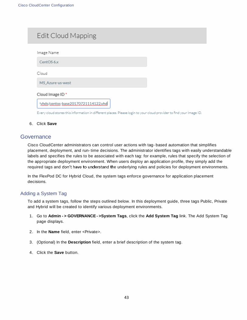
5. On the CCM GUI, click Add Mapping for CentOS 6.x.
6. In the pop-up window, enter the Cloud Image ID. In VMware Clouds, the Cloud Image ID is <VM name>
/ <snapshot name>.
7. Expand Advanced Instance Type Configuration and select indivi .

Cisco CloudCenter Configuration
35
8. Click Save to complete the image mapping for CentOS 6.
The Private Cloud addition to the CloudCenter is now complete.
Adding AWS to Cisco CloudCenter
To configure the AWS Public Cloud in Cisco CloudCenter, refer to the following document (Configure an
AWS Cloud):
http://docs.cloudcenter.cisco.com/pages/viewpage.action?pageId=5540210
To connect to AWS, enter the required information shown in the figure below:

Cisco CloudCenter Configuration
36
The account information and the security credentials can be obtained by clicking the account email id on the
top left corner of AWS console:
Cloud Region
In AWS based Public Cloud, follow the procedure below to add a Cloud Region and configure the CCM to
communicate to CCO.
1. Navigate to Admin->Clouds section in the CloudCenter GUI. Click on the AWS cloud defined in the last
step and then select Configure Cloud and then Add Region.
2. Select the appropriate region and click Save:

Cisco CloudCenter Configuration
37
The Instance Types, Storage Types and Image Mappings are automatically populated for AWS when the re-gion is added to the CloudCenter.
3. When the main-panel updates, click on Edit Cloud Settings and select default for Instance Naming
Strategy and No IPAM for IPAM Strategy.
4. Click Configure Orchestrator
5. Enter the Public IP address for the Orchestrator in AWS.
6. The Remote Desktop Gateway is the Public IP address of the RabbitMQ VM in AWS where Guacamole
will handle any remote connections to the applications.
7. The Cloud Account field will associate the Region with AWS Cloud

Cisco CloudCenter Configuration
38
8. Click Save.
Before configuring the Orchestrator, make sure the CCO and AMQP configuration has been completed using the appropriate wizards
The AWS Cloud addition to the CloudCenter is now complete.
Adding MS Azure RM to Cisco CloudCenter
To add an Azure RM cloud to the CloudCenter, verify the following requirements:
Login to the Azure CLI's ARM mode and register the required Azure providers
Set App Permissions and generate keys in Azure Resource Manager Portal
To setup these initial configuration parameters, visit
http://docs.cloudcenter.cisco.com/pages/viewpage.action?pageId=5540210
-> Prerequisites.
After the pre-requisites are configured successfully, proceed to configure the MS Azure Public Cloud in
Cisco CloudCenter using the instructions at the same URL.
The figure below shows the required information to connect to the Azure.

Cisco CloudCenter Configuration
39
The information required to fill the form is explained at the URL and was generated as part of completing the
pre-requisites.
Cloud Region
In Azure based Public Cloud, follow the procedure below to add a Cloud Region and configure the CCM to
communicate to CCO.
1. Navigate to Admin->Clouds section in the CloudCenter GUI. Click on the Azure cloud defined in the last
step and then select Configure Cloud and then Add Region.
2. Select the appropriate region and click Save:

Cisco CloudCenter Configuration
40
The Instance Types, Storage Types and Image Mappings are automatically populated for AWS when the re-
gion is added to the CloudCenter.
3. When the main-panel updates, click Edit Cloud Settings and verify the default settings. Do not change
the values unless advised by a CloudCenter expert.
4. Click Configure Orchestrator.
5. Enter the Public IP address for the Orchestrator in Azure.
6. The Remote Desktop Gateway is the Public IP address of the RabbitMQ VM in Azure where Guacamole
will handle any remote connections to the applications.
7. The Cloud Account field will associate the Region with Azure Cloud.

Cisco CloudCenter Configuration
41
8. Click Save.
Before configuring the Orchestrator, make sure the CCO and AMQP configuration has been completed using the appropriate wizards
The MS Azure RM Cloud addition to the CloudCenter is now complete. If a customer base image, mag-
was previously created, this image can now be re-mapped.
Image Mapping (Optional)
1. In a new web browser window, access MS Azure Console, click on All Resources and scroll down and
click the previously capture Image (mag-centos6 in our example)
2. From the main page, click the copy button to copy the SOURCE BLOB URI

Cisco CloudCenter Configuration
42
3. Back at the CloudCenter Azure Region configuration window, scroll down to Image Mappings section
of the configuration
4. Click Edit Mapping next to CentOS 6.x
5. Paste the copied BLOB URI in the Cloud Image ID box
Cisco CloudCenter Configuration
43
6. Click Save
Governance
Cisco CloudCenter administrators can control user actions with tag-based automation that simplifies
placement, deployment, and run-time decisions. The administrator identifies tags with easily understandable
labels and specifies the rules to be associated with each tag: for example, rules that specify the selection of
the appropriate deployment environment. When users deploy an application profile, they simply add the
required tags and e underlying rules and policies for deployment environments.
In the FlexPod DC for Hybrid Cloud, the system tags enforce governance for application placement
decisions.
Adding a System Tag
To add a system tags, follow the steps outlined below. In this deployment guide, three tags Public, Private
and Hybrid will be created to identify various deployment environments.
1. Go to Admin -> GOVERNANCE ->System Tags, click the Add System Tag link. The Add System Tag
page displays.
2. In the Name field, enter <Private>.
3. (Optional) In the Description field, enter a brief description of the system tag.
4. Click the Save button.

Cisco CloudCenter Configuration
44
5. Repeat the steps to create two additional tags labeled Public and Hybrid.
Enforce Governance rules
1. On CloudCenter GUI, go to Admin -> GOVERNANCE -> Governance Rules
2. Enable rules-based governance by clicking the ON toggle button
The System tags defined in are ready to be utilized for selecting the deployment environment.
Setting up Deployment Environment
A deployment environment is a resource that consists of one or more associated cloud regions that have
been set aside for specific application deployment needs. The clouds defined previously can now be setup
as deployment environments and the selection of these deployment environments for an application instance
will be determined by the system tags defined in the previous section.
Private Cloud Environment
For setting up the private cloud as a deployment environment, a dedicated ACI tenant named App-A is
selected to host all the application instances. The application tenant creation is covered in detail in the
FlexPod with ACI Design Guide:
http://www.cisco.com/c/en/us/td/docs/unified_computing/ucs/UCS_CVDs/flexpod_esxi60u1_n9k_aci_desi
gn.html
To successfully deploy an application, the following requirements need to be met:

Cisco CloudCenter Configuration
45
An application profile and an EPG(s) needs to be pre-provisioned under the tenant
A DHCP server needs to be setup to assign IP addresses to the VMs
The DNS server should be able to resolve the IP addresses for the CloudCenter components
An L3-Out or Shared L3-Out providing VMs ability to access Internet
To setup the ACI environment as outlined, following configurations were performed:
Two Application Profiles were added to tenant App-A as follows:
CliQr
EPG Web mapped to Bridge Domain BD-Internal to host Application VMs
CliQr-Services
EPG DHCP mapped to Bridge Domain BD-Internal to host the DHCP server. A DNS server can also
be hosted in this EPG with appropriate contracts defined to enable EPG to EPG communication.
In this deployment, DNS server is accessible over the Shared L3Out and therefore not deployed within the tenant
Shared L3Out contract is consumed by all the Application EPGs to provide access Internet access to all the
VMs.
To add a deployment environment to Cisco CloudCenter, complete the following steps.
1. Log into the Cisco CloudCenter GUI.
2. On the CloudCenter console, Go to Deployments and select Environments in the main window
3. Click New Environment to add a new deployment environment

Cisco CloudCenter Configuration
46
4. In the General Settings section, provide the deployment environment NAME x-
ample)
5. (Optional) Provide a DESCRIPTION.
6. In the Cloud Selection section, select the checkbox for FlexPod.
7. Select the Cloud Account from the dropdown list if not auto-selected .

Cisco CloudCenter Configuration
47
8. Click DEFINE DEFAULT CLOUD SETTINGS
9. Multiple Instance Type to enable one or more instance types (Small,
Medium and Large)
10. Under Cloud Settings, select DATA CENTER from the drop-down menu (FlexPod-DC in this example)
11. Select CLUSTER name from the drop-down menu (App-A in this example)
12. (Optional) Create a folder to host the VMs deployed by CloudCenter and map the folder under TARGET
DEPLOYMENT FOLDER
13. Select the port-group where the VM needs to be deployed under NETWORK
14. Leave No Preference selected under SSH Options

Cisco CloudCenter Configuration
48
15. Click DONE
16. Click DONE again to finish adding the deployment environment
17. Under Deployments, the recently added environment should appear. Hover the mouse over the name of
the deployment and an Action drop-down box appears
18. Asso
19. In the windows that appears, c
Click Add. Click Close
The Private Cloud deployment environment is now ready. When a customer deploys a new application in
CloudCenter
new deployment.
Public Cloud Environment
For setting up both AWS and Azure as Public Cloud deployment options, follow the steps outlined below.
1. Log into the Cisco CloudCenter GUI.
2. On the CloudCenter console, Go to Deployments and select Environments in the main window
3. Click New Environment to add a new deployment environment

Cisco CloudCenter Configuration
49
4. In the General Settings section, provide the deployment environment NAME Public in this ex-
ample)
5. (Optional) Provide a DESCRIPTION.
6. In the Cloud Selection section, select the checkbox for AWS and Azure.
7. Select the Cloud Account from the dropdown list (if the information is not automatically selected).
8. Click on DEFINE DEFAULT CLOUD SETTINGS
9. Select AWS Account from the left menu
10. Instance Type to enable one or more instance types and select
the instance types that the end-users can use for their deployments. In this example, three smaller in-
stances were selected as deployment option.

Cisco CloudCenter Configuration
50
11. Under Cloud Settings, select VPC from the drop-down menu
12. Leave ASSIGN PUBLIC IP ON
13. Select the NIC1 NETWORK subnet to match the single subnet dedicated for VM deployment
(172.31.0.0/20 in this example)
14. Set SSH Options

Cisco CloudCenter Configuration
51
15. Scroll back up and select MS Azure Account from the left menu
16. Instance Type to enable one or more instance types and select
the instance types that the end-users can use for their deployments
Cisco CloudCenter Configuration
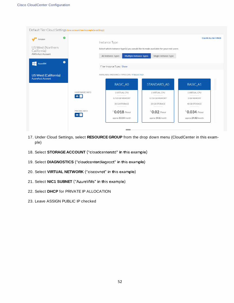
52
17. Under Cloud Settings, select RESOURCE GROUP from the drop down menu (CloudCenter in this exam-
ple)
18. Select STORAGE ACCOUNT
19. Select DIAGNOSTICS
20. Select VIRTUAL NETWORK
21. Select NIC1 SUBNET
22. Select DHCP for PRIVATE IP ALLOCATION
23. Leave ASSIGN PUBLIC IP checked

Cisco CloudCenter Configuration
53
24. Set SSH Options
25. Click DONE
26. Click DONE again to finish adding the deployment environment
27. Under Deployments, the recently added environment should appear. Hover the mouse over the name of
the deployment and an Action drop-down box appears
28.
29. Public
Click Add. Click Close

Cisco CloudCenter Configuration
54
The Public Cloud deployment environment is now ready. When a customer deploys a new application in
Public both AWS and Azure clouds are provided as options for
the new deployment.
Hybrid Cloud Environment
For setting up a Hybrid Cloud environment, add all three clouds to a new deployment called HybridCloud and
setup the defaults as covered in the last two environment setup. When the configuration is complete, assign
the system tag as follows:
1. Under Deployments, the recently added environment should appear. Hover the mouse over the name of
the deployment and an Action drop-down box appears
2.
3. In the windows th Hybrid
Click Add. Click Close
The Hybrid Cloud deployment environment is now ready. When a customer deploys a new application in
Hybrid ag, all three clouds are provided as options for the new
deployment. The VPN connectivity setup in the next section will provide the necessary connectivity between
the VMs deployed in the Public and Private clouds.
This deployment only supports selecting single Public Cloud combined with the Private Cloud for delivering a Hybrid deployment option. The validation was performed by deploying the database server on the private cloud and web server on the public cloud
Private to Public Cloud Connectivity
55
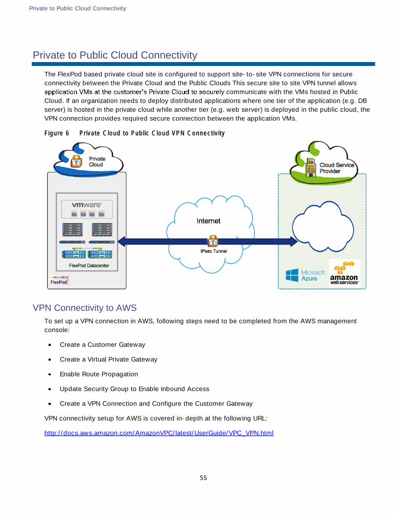
Private to Public Cloud Connectivity
The FlexPod based private cloud site is configured to support site-to-site VPN connections for secure
connectivity between the Private Cloud and the Public Clouds This secure site to site VPN tunnel allows
ly communicate with the VMs hosted in Public
Cloud. If an organization needs to deploy distributed applications where one tier of the application (e.g. DB
server) is hosted in the private cloud while another tier (e.g. web server) is deployed in the public cloud, the
VPN connection provides required secure connection between the application VMs.
Figure 6 Private Cloud to Public Cloud VPN Connectivity
VPN Connectivity to AWS
To set up a VPN connection in AWS, following steps need to be completed from the AWS management
console:
Create a Customer Gateway
Create a Virtual Private Gateway
Enable Route Propagation
Update Security Group to Enable Inbound Access
Create a VPN Connection and Configure the Customer Gateway
VPN connectivity setup for AWS is covered in-depth at the following URL:
http://docs.aws.amazon.com/AmazonVPC/latest/UserGuide/VPC_VPN.html

Private to Public Cloud Connectivity
56
An IPsec tunnel to AWS can only be established by initiating data traffic from the Private Cloud. Customers need to ensure there is a continuous data exchange between the FlexPod and AWS clouds to keep the tunnel up at all times.
Create Customer Gateway
To create a customer gateway, complete the following steps:
1. Open the Amazon VPC console at https://console.aws.amazon.com/vpc/.
2. In the navigation pane, choose Customer Gateways, and then Create Customer Gateway.
3. In the Create Customer Gateway dialog box, enter a name for the customer gateway.
4. Select Static as the routing type from the Routing list.
5. Enter the IP address of Customer ASA. Click Yes, Create.
Create Virtual Private Gateway
To create a virtual private gateway, complete the following steps:
1. In the navigation pane, choose Virtual Private Gateways, and then Create Virtual Private Gateway.
2. Enter a name for the virtual private gateway, and then choose Yes, Create.
3. Select the virtual private gateway that was just created, and then choose Attach to VPC.
4. In the Attach to VPC dialog box, select the VPC (default VPC) from the list, and then choose Yes, At-
tach.
Enable Route Propagation
To enable route propagation, complete the following steps:
1. In the navigation pane, choose Route Tables, and then select the route table that's associated with the
subnet; by default, this is the main route table for the VPC.
2. On the Route Propagation tab in the details pane, choose Edit, select the virtual private gateway that
was created in the previous procedure, and then choose Save.
Update the Security Group
To add rules to the security group to enable inbound access, complete the following steps:
3. In the navigation pane, choose Security Groups, and then select the default security group for the VPC.
4. On the Inbound tab in the details pane, add rules to allow inbound traffic from the customer network,
and then choose Save. For this deployment, all inbound traffic was allowed for the default security
group.
While allowing ALL inbound traffic for the Default Security Group works well for testing environment, custom-ers should limit the communication based on the application being deployed

Private to Public Cloud Connectivity
57
Create a VPN Connection and Configure the Customer Gateway
To create a VPN connection, complete the following steps:
1. In the navigation pane, choose VPN Connections, and then Create VPN Connection
2. In the Create VPN Connection dialog box, enter a name for the VPN connection
3. Select the virtual private gateway that was created earlier
4. Select the customer gateway that was created earlier
5. Select Static as the routing options
6. In the Static IP Prefixes field, specify each IP prefix for the private network (FlexPod DC location) of your
VPN connection, separated by commas
7. Click Yes, Create
8. It may take a few minutes to create the VPN connection. When it's ready, select the connection, and
then choose Download Configuration
9. In the Download Configuration dialog box, select the vendor, platform, and software that corresponds to
gateway device or software, and then choose Yes, Download.

Private to Public Cloud Connectivity
58
10. Use the configuration file to setup ASA to VPN connectivity
VPN Setup on FlexPod ASA
To set up a VPN connection on customer ASA, execute the following command. The following configuration
is derived from the configuration file downloaded in the last step:
interface GigabitEthernet0/0
nameif outside
security-level 0
ip address 64.100.x.x 255.255.255.252 << Public IP Address of ASA
!
interface GigabitEthernet0/1.163
vlan 163
nameif inside
security-level 100
ip address 172.26.163.1 255.255.255.0 << Private IP address of ASA
!
! All VMs on AWS will be deployed in 172.31.0.0/16 subnet
!
access-list acl-amzn extended permit ip 172.16.150.0 255.255.255.0 172.31.0.0 255.255.0.0
!
! Route to access Private Cloud VMs network
!
route inside 172.16.150.0 255.255.255.0 172.26.163.9 1
!
crypto ipsec transform-set ESP-AES-128-SHA esp-aes esp-sha-hmac
!
crypto ipsec security-association lifetime seconds 28800
crypto ipsec df-bit clear-df outside
!
crypto map outside_map 2 match address acl-amzn
crypto map outside_map 2 set pfs
crypto map outside_map 2 set peer 52.8.x.x 52.52.x.x << Redundant Peers provided by AWS
crypto map outside_map 2 set transform-set ESP-AES-128-SHA
crypto map outside_map 2 set security-association lifetime seconds 3600
!
crypto isakmp enable outside
crypto isakmp policy 10
authentication pre-share
encryption aes
hash sha
group 2
lifetime 28800
!
tunnel-group 52.8.x.x type ipsec-l2l
tunnel-group 52.8.x.x ipsec-attributes

Private to Public Cloud Connectivity
59
pre-shared-key *****
isakmp keepalive threshold 10 retry 10
tunnel-group 52.52.x.x type ipsec-l2l
tunnel-group 52.52.x.x ipsec-attributes
pre-shared-key *****
isakmp keepalive threshold 10 retry 10
!
VPN connectivity to Azure
To set up a VPN connection for Azure, the following steps need to be completed from the Azure portal:
Create a Gateway Subnet (already completed)
Create a Virtual Network Gateway
Create a Local Network Gateway
Create the VPN Connection
Create a Virtual Network Gateway
1. Log into the Azure Portal
2. On the left side of the portal page, click + and type 'Virtual Network Gateway' in search. In Results, lo-
cate and click Virtual network gateway.
3. Provide a Name for the Virtua network gateway (FlexPod-VPN in this example)
4. Set Gateway type as VPN
5. Set VPN type as Route-based
6. Select the previously configured Virtual network
7. Click Choose a Public IP address and click + Create new. Provide a Name for the IP address (FlexPod-
VPN-IP in this example) and click OK
8. Select appropriate Subscription
9. Select appropriate Location ( West US in this example)

Private to Public Cloud Connectivity
60
10. Click Create
According to MS documentation: https://docs.microsoft.com/en-us/azure/vpn-gateway/vpn-gateway-about-vpn-gateway-settings, policy-based VPN connection (IKEv1 and ACL based VPN supported by ASA) can only be used with the “Basic” SKU for VPN GW. However, when using both Express Route and VPN GW at the same time, “Basic” SKU is not supported therefore “Route-based” VPN type and Standard SKU need to be selected for VPN deployment

Private to Public Cloud Connectivity
61
Create a Local Network Gateway
The local network gateway typically refers to the on-premises location. In this scenario, this gateway refers
to the CSR/ASR/ISR on the FlexPod DC site.
https://docs.microsoft.com/en-us/azure/vpn-gateway/vpn-gateway-about-vpn-devices provides a list of validat-ed VPN devices on the customer premise and the appropriate configuration. To satisfy the IKEv2 requirements on the GW, Cisco CSR was deployed as the local Virtual Network Gateway.
1. Log into the Azure Portal
2. On the left side of the portal page, click + and type Network Gateway' in search. In Results, lo-
cate and click Local network gateway.
3. Provide a Name for the Virtual network gateway (FlexPod in this example)
4. In the IP address field, provide the public IP address of the CSR
5. In the Address Space field, add private subnet (VM subnet) on the FlexPod DC site
6. Select the previously configured Resource group CloudCenter
7. Select appropriate Subscription
8. Select appropriate Location (West US in this example)

Private to Public Cloud Connectivity
62
9. Click Create
Create the VPN Connection
Create the Site-to-Site VPN connection between the virtual network gateway and on-premises VPN device.
1. In Azure console, navigate to All resources -> FlexPod-VPN (Virtual network gateway)
2. Click Connections. At the top of the Connections screen, click + Add
3. Provide a Name for the connection (AzuretoFlexPod in this example)
4. In the Connection type field, select Site-to-site (IPsec)
5. In the Virtual network gateway, select FlexPod-VPN
6. In the Local network gateway, select FlexPod
7. In the Shared key (PSK), provide a pre-shared key to be used for the connection
8. Select the previously configured Resource group

Private to Public Cloud Connectivity
63
9. Click OK
IPsec configuration in MS Azure is complete at this point and on premise VPN device needs to be configured
to complete the VPN setup.
VPN Setup on Local VPN device
To set up a VPN connection for on premise VPN device, following page outlined various configuration
examples: https://docs.microsoft.com/en-us/azure/vpn-gateway/vpn-gateway-about-vpn-devices. The
configuration used to validate this design is based on the document: https://github.com/Azure/Azure-vpn-
config-samples/blob/master/Cisco/Current/ASR/Site-to-Site_VPN_using_Cisco_ASR.md
crypto ikev2 proposal azure-proposal
encryption aes-cbc-256 aes-cbc-128 3des
integrity sha1
group 2
!
crypto ikev2 policy azure-policy
proposal azure-proposal
!
crypto ikev2 keyring azure-keyring
peer 104.X.X.X

Private to Public Cloud Connectivity
64
address 104.X.X.X
pre-shared-key <REMOVED>
!
!
!
crypto ikev2 profile azure-profile
match address local interface Loopback0
match identity remote address 104.X.X.X 255.255.255.255
authentication local pre-share
authentication remote pre-share
keyring local azure-keyring
!
interface Loopback0
ip address 64.100.X.X 255.255.255.255
!
interface Tunnel1
ip address 169.254.0.1 255.255.255.0
ip tcp adjust-mss 1350
tunnel source Loopback0
tunnel mode ipsec ipv4
tunnel destination 104.X.X.X
tunnel protection ipsec profile azure-vti
!
interface GigabitEthernet1
ip address 192.168.160.10 255.255.252.0
negotiation auto
!
interface GigabitEthernet2
ip address 172.26.163.101 255.255.255.0
negotiation auto
!
ip route 0.0.0.0 0.0.0.0 192.168.160.1
ip route 10.171.160.0 255.255.255.0 Tunnel1
ip route 172.16.150.0 255.255.255.0 172.26.163.9
!
When the on-premise device configuration is complete, the IPsec tunnel between Azure and FlexPod DC is
established.

OpenCart Application Configuration using Cisco CloudCenter
65
OpenCart Application Configuration using Cisco CloudCenter
Application Profiles in CloudCenter are templates or blueprints that can be used to describe how
applications should be deployed, configured, and managed on various cloud environments. Visit:
http://docs.cloudcenter.cisco.com/display/CCD46/Application+Profile for more information on how to
develop application profiles for multi-tier applications.
CloudCenter application modeling uses a base OS image (CentOS 6 in this document) mapped into
CloudCenter for all available cloud options and installs and configures various services (Web, DB etc.) to
deliver the application. The application packages, data, and scripts used to configure an application are
hosted at a common repository (e.g. cloud based web server) which is accessible from all the available
deployment environments.
Cisco CloudCenter team has developed various application profiles which can be requested through the
CloudCenter Technical Marketing team. These application profiles are provided as a ZIP file that can be
easily imported into the CloudCenter. This pre-defined application profile contains application profile
definition and links to repositories containing necessary binaries and scripts for automated deployment of the
application across VMware, AWS or Azure.
Setting up a CloudCenter Repository
To setup a new HTTP based repository to host application binaries and scripts, complete the following steps:
1. Login to CloudCenter Manager, click the double >> on the left menu to expand the navigation tray. Se-
lect the Repositories
2. In the main-panel, available repositories will be displayed (if any exists). To create a new repository,
click + Add Repository
3. Provide a Name for the Repository
4. Select the Type as HTTP

OpenCart Application Configuration using Cisco CloudCenter
66
5. Provide the Hostname of the HTTP server where the application binaries and scripts are hosted
6. Click Save to finish adding the repository
Importing Application Profile
To import an application profile obtained from the CloudCenter Technical Marketing team in the
CloudCenter:
1. In the left-hand pane, click on the double >> to expand the navigation menu. Select Applications

OpenCart Application Configuration using Cisco CloudCenter
67
2. In the main-panel, click Import and select Profile Package
3. Click Upload Profile Package in the pop-up window
4. Select the ZIP file for the OpenCart application saved on local PC
5. CloudCenter validates the format and displays the application in the Applications tab. The imported pro-
file is now available for deployment
Deploying a Production Instance of OpenCart in FlexPod Private Cloud
To deploy OpenCart application on FlexPod Private Cloud, complete the following steps:
1. Log into the CCM GUI and select Applications from the left menu
2. Search for the required OpenCart application profile in the Applications page and click on the profile to
begin the deployment process

OpenCart Application Configuration using Cisco CloudCenter
68
3. When the main-panel refreshes, complete the General Information section. Name the Deploy-
ment “OC-Prod (or similar) and select from the TAGS dropdown menu
4. Click NEXT
5. Select the VMware based FlexPod Private Cloud to deploy the application
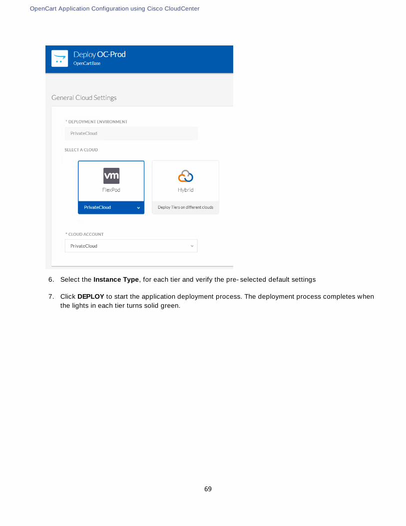
OpenCart Application Configuration using Cisco CloudCenter
69
6. Select the Instance Type, for each tier and verify the pre-selected default settings
7. Click DEPLOY to start the application deployment process. The deployment process completes when
the lights in each tier turns solid green.

OpenCart Application Configuration using Cisco CloudCenter
70
8. Click Access OpenCart App to access the application via browser
(Optional) Deploy Application Profile on Public and Hybrid Clouds
Repeat the steps listed above to deploy the application on AWS, Azure or in a Hybrid environment. The
correct system tag (Public or Hybrid) will have to be applied to select the appropriate deployment
environment

OpenCart Application Configuration using Cisco CloudCenter
71
(Optional) Delete an Application Instance
1. To delete a particular application instance, select Deployments from the left menu
2. Hover the mouse over the application instance so that Action drop down menu appears
3. Terminate A.. delete the application instance and remove the VMs as-
sociated with a deployed instance

NetApp Private Storage
72
NetApp Private Storage
Equinix Datacenter Requirements
Use the NetApp Hardware Universe or contact the NetApp account team to determine the power and space
requirements for the NetApp storage to be deployed in the Equinix datacenter. See the Cisco technical
specifications for the power and space requirements of the network equipment to be deployed.
It is recommended that customers use redundant power connections connected to separate power distribution
units (PDUs) so that the NetApp Private Storage solution can survive the loss of a single power connection. The
typical power connection configuration used with NetApp Private Storage is 208V/30A single-phase AC power.
The voltage specifications may vary from region to region. Contact your Equinix account team for more
information about the available space and power options in the Equinix data center where you want to deploy
NetApp Private Storage.
If more than six ports of power are required on a PDU, customers will need to purchase a third-party PDU or
order additional power connections from Equinix. Equinix sells PDUs that fit well with its cabinets. The Equinix
cabinets are standard 42U, 4-post racks. Contact your NetApp account team to make sure that the appropriate
rail kits are ordered. If using a secure cabinet in a shared cage, a top-of-rack demarcation panel must be
ordered to connect the network equipment to AWS. The type of demarcation panel should be 24-port SC
optical.
TR-4133: NetApp Private Storage for Amazon Web Services Solution Architecture and Deployment Guide provides detailed requirements, solution architecture and deployment details for NPS/AWS connectivity.
TR-4316: NetApp Private Storage for Microsoft Azure Solution Architecture and Deployment Guide provides detailed requirements, solution architecture and deployment details for NPS/Azure connectivity.
ASA VPN Connectivity
A Cisco ASA located in the Equinix colocation facility provides VPN capabilities to NPS to establish VPN
connectivity between the storage controllers in NPS and the storage controllers in FlexPod for SnapMirror
operations. The VPN link can also be utilized for managing the storage controllers or specific Storage Virtual
Machines (SVM).
The IPsec tunnel parameters to setup this connectivity in the current design are listed in Table 3 .
Table 3 IPsec Tunnel Details for NPS Connectivity
Parameter Value
IKE (Phase 1)
Authentication Pre-Shared

NetApp Private Storage
73
Parameter Value
Encryption AES 128
Hash SHA
DH Group 2
Lifetime 28800 seconds
IPsec (Phase 2)
Network Source and Destination depend on deployment
PFS On
Peers IP addresses of FlexPod and NPS ASAs
Transform Set AES-128, SHA-HMAC
IPsec SA Lifetime 3600 seconds
VPN Setup on Local VPN device
To set up a VPN connection for on premise VPN device, enter the following:
interface GigabitEthernet0/0
nameif outside
security-level 0
ip address 64.100.x.x 255.255.255.252 << Public IP Address of ASA
!
interface GigabitEthernet0/1.163
vlan 163
nameif inside
security-level 100
ip address 172.26.163.1 255.255.255.0 << Private IP address of ASA
!
! NPS Side Subnet is 172.17.0.0/24 subnet
!
access-list nps-acl extended permit ip 172.26.163.0 255.255.255.0 172.17.0.0 255.255.255.0
!
crypto ipsec transform-set ESP-AES-128-SHA esp-aes esp-sha-hmac
!
crypto ipsec transform-set ESP-AES-128-SHA esp-aes esp-sha-hmac
crypto map outside_map 1 match address nps-acl
crypto map outside_map 1 set pfs
crypto map outside_map 1 set peer 199.19.x.x
crypto map outside_map 1 set transform-set ESP-AES-128-SHA
crypto isakmp enable outside
crypto isakmp policy 10

NetApp Private Storage
74
authentication pre-share
encryption aes
hash sha
group 2
lifetime 28800
tunnel-group 199.19.x.x type ipsec-l2l
tunnel-group 199.19.x.x ipsec-attributes
pre-shared-key *****
Network Connectivity
To provide network connectivity between the NPS storage system and the various cloud and VPN networks,
a Layer 3 network switch is required. This solution uses Cisco Nexus 5548s for providing network
connectivity, but customers can use any Cisco layer-3 network switch that meets the following
requirements:
Has Border Gateway Protocol BGP licensed and enabled
Has at least one 9/125 single-mode fiber (SMF) 1Gbps or 10Gbps port available
Has 1000BASE-T Ethernet ports
Supports 802.1Q VLAN tags
The steps to set up the customer-provided network switch, at a high level, are as follows:
1. Perform the initial switch configuration (host name, SSH, user names, and so on).
2. Create and configure the virtual local area network (VLAN) interface.
3. Create and configure the virtual routing and forwarding (VRF) instances.
TR-4133: NetApp Private Storage for Amazon Web Services Solution Architecture and Deployment Guide provides detailed requirements, solution architecture and deployment details for NPS/AWS connectivity.
TR-4316: NetApp Private Storage for Microsoft Azure Solution Architecture and Deployment Guide provides detailed requirements, solution architecture and deployment details for NPS/Azure connectivity.
Storage Configuration
The steps to configure the NetApp storage are listed below. Create the appropriate VLAN interface ports on
cluster nodes (according to the VLAN configuration on the Cisco Nexus Switch).
1. Create a storage virtual machine (SVM) on the cluster.
2. Create logical interfaces (LIFs) on the SVM that uses the VLAN interface ports:
a. Management LIFs
b. CIFS/NFS LIFs
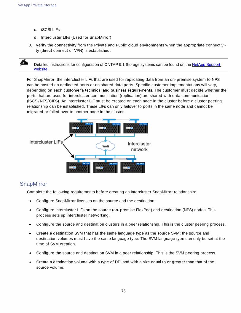
NetApp Private Storage
75
c. iSCSI LIFs
d. Intercluster LIFs (Used for SnapMirror)
3. Verify the connectivity from the Private and Public cloud environments when the appropriate connectivi-
ty (direct connect or VPN) is established.
Detailed instructions for configuration of ONTAP 9.1 Storage systems can be found on the NetApp Support website.
For SnapMirror, the intercluster LIFs that are used for replicating data from an on-premise system to NPS
can be hosted on dedicated ports or on shared data ports. Specific customer implementations will vary,
depending on each cust The customer must decide whether the
ports that are used for intercluster communication (replication) are shared with data communication
(iSCSI/NFS/CIFS). An intercluster LIF must be created on each node in the cluster before a cluster peering
relationship can be established. These LIFs can only failover to ports in the same node and cannot be
migrated or failed over to another node in the cluster.
SnapMirror
Complete the following requirements before creating an intercluster SnapMirror relationship:
Configure SnapMirror licenses on the source and the destination.
Configure Intercluster LIFs on the source (on-premise FlexPod) and destination (NPS) nodes. This
process sets up intercluster networking.
Configure the source and destination clusters in a peer relationship. This is the cluster peering process.
Create a destination SVM that has the same language type as the source SVM; the source and
destination volumes must have the same language type. The SVM language type can only be set at the
time of SVM creation.
Configure the source and destination SVM in a peer relationship. This is the SVM peering process.
Create a destination volume with a type of DP, and with a size equal to or greater than that of the
source volume.

NetApp Private Storage
76
Assign a schedule to the SnapMirror relationship in the destination cluster to perform periodic updates.
If any of the existing schedules do not meet business requirements then custom schedules can be
created.
After the intercluster LIFs have been created and the intercluster network has been configured, cluster peers
can be created. A cluster peer is a cluster that can replicate to or from another cluster.
Cluster and SVM Peering
Clusters must be joined in a peer relationship before replication between different clusters is possible.
Cluster peering is a one-time operation that must be performed by the cluster administrators. The cluster
peer feature allows two clusters to coordinate and share resources between them.
Cluster peering must be performed because this defines the network on which all replication between
different clusters occurs. Cluster peer intercluster connectivity consists of intercluster logical interfaces (LIFs)
that are assigned to network ports or ifgroups. The intercluster connection on which replication occurs
between two different clusters is defined when the intercluster LIFs are created. Replication between two
clusters can occur on the intercluster connection only; this is true regardless of whether the intercluster
connectivity is on the same subnet as a data network in the same cluster.
Additionally, once the clusters are peered, SVMs must be joined in a peer relationship before replication
between different SVMs is possible.
An SVM peer relationship is an authorization infrastructure that enables a cluster administrator to set up
peering applications such as SnapMirror relationships between SVMs either existing within a cluster
(intracluster) or in the peered clusters (intercluster). Only a cluster administrator can set up SVM peer
relationships.
There are various pre-requisites that need to be satisfied before a SnapMirror relationship can be established. For detailed guidance regarding SnapMirror configuration, please refer to the Data Protection using SnapMir-ror and SnapVault Technology Guide.
Volume SnapMirror Configuration
When the cluster and SVMs are peered you can create and initialize the SnapMirror relationship to replicate
data from the FlexPod private cloud to NPS.
The source volume at the FlexPod on-premise datacenter is created as part of the “Application Deployment using NPS” section below. This procedure assumes the source volume already exists and hosts the Opencart e-commerce application data.
1. Create a destination volume on the destination SVM that will become the data protection mirror copy by
using the volume create command. This step will be performed on the NPS system in the Equinix data
center.
Example:
The following command creates a data protection mirror volume named cloud_mirror1 on SVM
dest.opencart.com. The destination volume is located on an aggregate named aggr1.

NetApp Private Storage
77
dest::> vol create -volume cloud_dest_mirror -aggregate aggr1 -size 100MB -type DP
2. Create a data protection mirror relationship between the FlexPod on-premise source volume and the
destination NPS volume by using the snapmirror create command.
Example:
Execute the following command on the destination SVM at the NPS location to create a SnapMirror
relationship:
dest::> snapmirror create -destination-path dest.opencart.com:cloud_mirror1 -source-path
source.opencart.com:flexpod_source1 -type DP -schedule 5min
Data ONTAP creates the data protection mirror relationship, but the relationship is left in an uninitialized
state.
dest::> snapmirror show
Progress
SourcePath Type DestinationPath Mirrorstate Relationshipstatus TotalProgress Healthy
ProgressLastupdated
----------- ---- ------------ ------- -------------- --------- ------- --------
source:flexpod_source1 DP dest:cloud_mirror1 Uninitialized Idle - true -
3. On the destination cluster, initialize the data protection mirror copy by using the snapmirror initialize
command.
Example:
dest::> snapmirror initialize -destination-path dest.opencart.com:cloud_mirror1
Operation is queued: snapmirror initialize of destination vs1R:vol1_vs1R.
dest::> snapmirror show
SourcePath Type DestinationPath Mirrorstate Relationshipstatus TotalProgress Healthy
ProgressLastupdated
----------- ---- ------------ ------- -------------- --------- ------- --------
source:flexpod_source1 DP dest:cloud_mirror1 Snapmirrored Idle - true -
NetApp OnCommand System Manager can also be used for creating and managing SnapMirror DP relation-ships. System Manager includes a wizard used to create SnapMirror DP relationships, create schedules to as-sign to relationships, and create the destination volume.
When the relationship has been initialized, assign a schedule to the SnapMirror transfers. Unless a schedule
is implement for SnapMirror transfers, destination FlexVol volumes should be manually updated with mirror
relationships.
Schedules
The Data ONTAP operating system has a built-in scheduling engine similar to cron. There are some default
schedules that can be used to update the relationship and this can be done by assigning a schedule to a
SnapMirror relationship on the destination cluster. If the default schedules do not satisfy the replication
requirements, then a custom schedule can be created through the command line using the job schedule
cron create command.
This example demonstrates the creation of a schedule called Hourly_SnapMirror that runs at the top of every
hour (on the zero minute of every hour).

NetApp Private Storage
78
cluster02::> job schedule cron create Hourly_SnapMirror -minute 0
cluster02::> job schedule cron show
Name Description
---------------- --------------------------------------------------
5min @:00,:05,:10,:15,:20,:25,:30,:35,:40,:45,:50,:55
8hour @2:15,10:15,18:15
Hourly_SnapMirror @:00
daily @0:10
hourly @:05
weekly Sun@0:15
The schedule can then be applied to a SnapMirror relationship at the time of creation using the schedule
option or to an existing relationship using the snapmirror modify command and the schedule option.
In this example, the Hourly_SnapMirror schedule is applied to the relationship we created in the previous
steps.
dest::> snapmirror modify -destination-path dest.opencart.com:cloud_mirror1 schedule Hourly_SnapMirror
Schedules can also be managed and applied to SnapMirror relationships using NetApp OnCommand System
Manager.
Policies
To manage a data protection mirror, vault, or mirror and vault relationship, a policy must be assigned to the
relationship. The policy is useful for maximizing the efficiency of the transfers. Data ONTAP uses polices to
dictate how many Snapshot copies need to be retained and/or replicated as a part of the relationship.
A default policy DPDefault is associated with the relationship. This policy can be viewed by issuing the
command:
dest::>snapmirror policy show -policy DPDefault -instance
Vserver: AFF8040
SnapMirror Policy Name: DPDefault
SnapMirror Policy Type: async-mirror
Policy Owner: cluster-admin
Tries Limit: 8
Transfer Priority: normal
Ignore accesstime Enabled: false
Transfer Restartability: always
Network Compression Enabled: false
Create Snapshot: true
Comment: Default policy for DP relationship.
Total Number of Rules: 1
Total Keep: 1
Rules:
SnapMirror Label Keep Preserve Warn Schedule Prefix
----------------------------- ---- -------- ---- -------- ----------
sm_created 1 false 0 - -
It is important to note the following:
The policy type is async-mirror. This is a standard SnapMirror relationship which mirrors data
asynchronously.
The Create Snapshot value is true.

NetApp Private Storage
79
There is a single rule, sm_created, with a retention policy of 1.
This means that the SnapMirror engine creates a Snapshot copy (using the standard SnapMirror naming
policy), then replicates the difference between the new SnapMirror Snapshot copy and the previous one (if
the relationship is being initialized, then a Snapshot copy is created and everything before it is replicated).
After the update is complete, the older Snapshot copy is deleted leaving just one SnapMirror Snapshot copy
in place.
NetApp OnCommand System Manager can also be used for creating and managing schedules and policies.
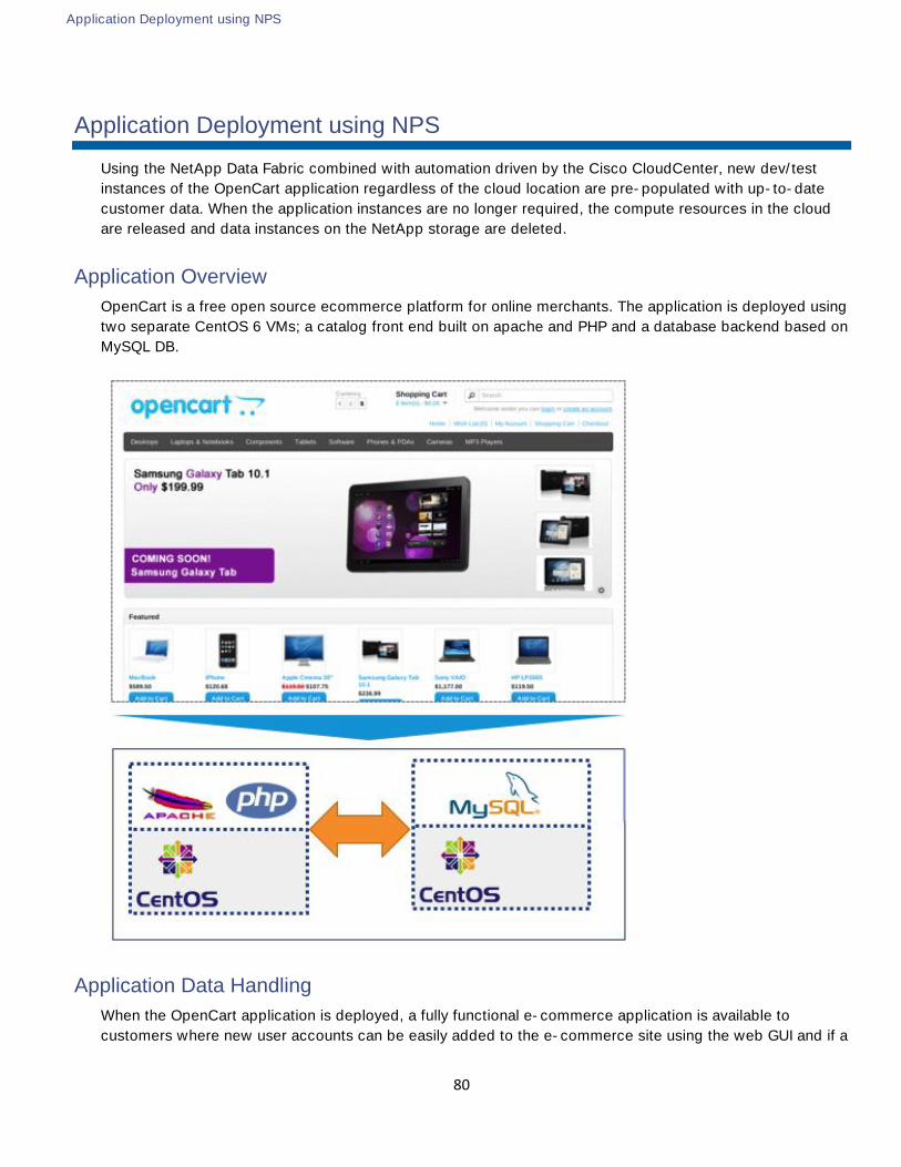
Application Deployment using NPS
80
Application Deployment using NPS
Using the NetApp Data Fabric combined with automation driven by the Cisco CloudCenter, new dev/test
instances of the OpenCart application regardless of the cloud location are pre-populated with up-to-date
customer data. When the application instances are no longer required, the compute resources in the cloud
are released and data instances on the NetApp storage are deleted.
Application Overview
OpenCart is a free open source ecommerce platform for online merchants. The application is deployed using
two separate CentOS 6 VMs; a catalog front end built on apache and PHP and a database backend based on
MySQL DB.
Application Data Handling
When the OpenCart application is deployed, a fully functional e-commerce application is available to
customers where new user accounts can be easily added to the e-commerce site using the web GUI and if a

Application Deployment using NPS
81
atabase. The cart
information can be later retrieved just like any other e-commerce website. OpenCart uses the following
directory information will be used to setup data migration in the data handling section.
There are several ways to automate the data replication of the OpenCart application. This deployment guide covers one of many available options. Customers can setup the data replication and delivery according to their individual requirements.
Modifying Production Instance of Application
Using the application blue print for OpenCart and selecting the Private Cloud as deployment locations,
production instance of the application was deployed in the last section. This instance was named OC-Prod
to identify it as production instance of the application.
To integrate the production copy of the application with NPS, the following changes need to be made to the
DB VM:
Create a Volume on local NetA and set up appropriate NFS mount-
point (/opencart)
Mount the volume on the database VM using NFS (/mnt/opencart); add the mount information to
/etc/fstab
Shutdown the MySQL services and move the OpenCart data from its current directory to the
recently mounted directory
Create a soft link at the previous directory location (/data/mysql/) to point to new data location (on
external storage)
Restart the MySql services
In the current deployment environment, using appropriate contracts, the application VMs being deployed can access NetApp controllers’ management address and therefore can access the controller (using SSH) to cre-ate and delete volumes and mount points.
The VMs also have access to the NFS LIFs on the Application APP-A Storage Virtual Machine (SVM) to mount and access the data volume. The EPGs and contracts enabling this communication are defined in the FlexPod with ACI design and deployment guides.

Application Deployment using NPS
82
Create the Volume and NFS Mount-Point and Export Policy
Log into the NetApp local storage using an admin (or SVM admin) account. This deployment assumes admin
user is logging into the NetApp controller. Issue the following commands to create a volume called
and make it available to the application VM:
export-policy rule create -vserver App-A-SVM -policy default -clientmatch <IP
address of VM> -rorule sys -rwrule sys -protocol nfs -superuser sys
volume create -vserver App-A-SVM -volume opencart -aggregate aggr1_node01 -size
5GB -state online -policy default -junction-path /opencart -space-guarantee none
-percent-snapshot-space 0
update-ls-set -source-path App-A-SVM:rootvol
The NFS mounted NetApp direc the production copy of the database. This
directory is replicated to NetApp Private Storage using snapmirror.
Mount the External Volume on the Database Virtual Machine
Log into the DB VM deployed using Cisco CloudCenter using the account
1. Log into the Cisco CloudCenter, select Deployments from the left menu
2. Click the Application OC-Prod
3. Select the DB VM from the application tiers and on the window on right, click on the arrow next to

Application Deployment using NPS
83
Customers are encouraged to change the default root password for future access.
Mount Directory:
mkdir /mnt/opencart
mount -t nfs 192.168.151.18:/opencart /mnt/opencart (where 192.168.151.18 is NFS LIF
on NetApp)
Verify:
mount | grep opencart
192.168.151.18:/opencart on /mnt/opencart type nfs (rw,addr=192.168.151.18)
Modify /etc/fstab:
Add the following entry to the file fstab:
192.168.151.18:/opencart /mnt/opencart nfs auto,noatime,nolock,bg,nfsvers=3,intr
,tcp,actimeo=1800 0 0
Save the file. The entry in /etc/fstab file makes NFS mount available across reboots.

Application Deployment using NPS
84
Shutdown the MySQL Services
Issue the following command to stop mysql service in preparation to move the data to external storage.
service mysqld stop
Move the OpenCart Data to External Storage
Copy the database to NFS storage mounted in the last step
cp -avr /data/mysql/opencart/* /mnt/opencart/
Remove the existing local data from the DB VM
rm -rf /data/mysql/opencart/
Create a soft link to point the current (removed) directory to NFS mounted directory
ln -s /mnt/opencart /data/mysql/opencart
Restart the MySql Services
When the data is in place, restart the mysql services and verify the application is working as expected
service mysqld start
Any new changed to database will be saved on the NFS share. The database has successfully been moved
to an external volume.
Data Availability across the Clouds
In the FlexPod DC for Hybrid Cloud, SnapMirror is used to replicate primary workload data from the on-
premises production site to NPS connected to both AWS and Azure. SnapMirror enables consistent data
availability across all the clouds and automates data replication. The data is kept in sync by using a
SnapMirror schedule.
When an instance of the application is deployed in the public cloud, the SnapMirror destination volume at
NPS is cloned to provide a dedicated storage-efficient data instances. If a customer chooses the private
cloud to deploy the application development or test instance, there is no need to setup SnapMirror. A copy
of the data volume is created on the FlexPod storage and mounted to the on-premise application
instance. The data replication and cloning concept is illustrated in the figure below:
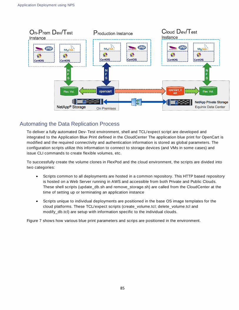
Application Deployment using NPS
85
Automating the Data Replication Process
To deliver a fully automated Dev-Test environment, shell and TCL/expect script are developed and
integrated to the Application Blue Print defined in the CloudCenter The application blue print for OpenCart is
modified and the required connectivity and authentication information is stored as global parameters. The
configuration scripts utilize this information to connect to storage devices (and VMs in some cases) and
issue CLI commands to create flexible volumes, etc.
To successfully create the volume clones in FlexPod and the cloud environment, the scripts are divided into
two categories:
Scripts common to all deployments are hosted in a common repository. This HTTP based repository
is hosted on a Web Server running in AWS and accessible from both Private and Public Clouds.
These shell scripts (update_db.sh and remove_storage.sh) are called from the CloudCenter at the
time of setting up or terminating an application instance
Scripts unique to individual deployments are positioned in the base OS image templates for the
cloud platforms. These TCL/expect scripts (create_volume.tcl; delete_volume.tcl and
modify_db.tcl) are setup with information specific to the individual clouds.
Figure 7 shows how various blue print parameters and scrips are positioned in the environment.

Application Deployment using NPS
86
Figure 7 Script Framework for Data Automation
Modifying Application Blue Print – Global Parameters
To configure the global parameters, complete the following steps:
1. Log into the CloudCenter GUI and select Applications from the left menu
2. Hover your mouse on the OpenCart application and from the drop-down menu, select Clone

Application Deployment using NPS
87
3. Select a version from the drop-down selection box and click OK
4. When the main window updates, click on the Basic Information tab at the top main window and select
5. Click on Global Parameters tab at the top of main window and click add a parameter >>
6. Enter LocalFilerIP as both the Parameter Name and Display Name
7. Set Type drop-down menu
8. Add the management IP address of the local NetApp controller as the Default Value (192.168.1.20 in
this example)
9. Leave the check boxes unchecked
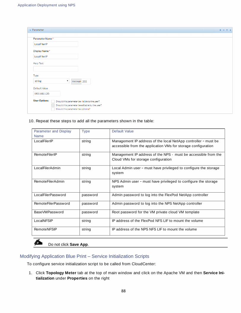
Application Deployment using NPS
88
10. Repeat these steps to add all the parameters shown in the table:
Parameter and Display
Name
Type Default Value
LocalFilerIP string Management IP address of the local NetApp controller must be
accessible from the application VMs for storage configuration
RemoteFilerIP string Management IP address of the NPS - must be accessible from the
Cloud VMs for storage configuration
LocalFilerAdmin string Local Admin user must have privileged to configure the storage
system
RemoteFilerAdmin string NPS Admin user must have privileged to configure the storage
system
LocalFilerPassword password Admin password to log into the FlexPod NetApp controller
RemoteFilerPassword password Admin password to log into the NPS NetApp controller
BaseVMPassword password Root password for the VM private cloud VM template
LocalNFSIP string IP address of the FlexPod NFS LIF to mount the volume
RemoteNFSIP string IP address of the NPS NFS LIF to mount the volume
Do not click Save App.
Modifying Application Blue Print – Service Initialization Scripts
To configure service initialization script to be called from CloudCenter:
1. Click Topology Meter tab at the top of main window and click on the Apache VM and then Service Ini-
tialization under Properties on the right

Application Deployment using NPS
89
2. Expand the Service Initialization Post-Start Script. Select the
appropriate HTTP repository <CliQrDemoRepo> from the drop-down menu
3. Click the Database VM and then Service Initialization under Properties on the right
4. Expand the Service Initialization pan Post-Stop Script. Select the
appropriate HTTP repository <CliQrDemoRepo> from the drop-down menu
5. Click Save App to save the application blueprint
Adding Scripts to Base Image
Scripts unique to individual deployments are positioned in the base OS image templates for the various
clouds. These TCL/expect scripts (create_volume.tcl; delete_volume.tcl and modify_db.tcl) are setup with
information specific to the individual clouds. To add these scripts to the base CentOS 6 Image, follow the
specific guidelines outlined below for all three clouds.
1. To identify the currently referenced images in the CloudCenter, Log into the CloudCenter GUI and navi-
gate to Admin -> Images. Click Manage Cloud Mapping next to CentOS 6.x image

Application Deployment using NPS
90
FlexPod Base Private Cloud
When the name of the base OS image is identified from the cloud mappings (mag-centos6/Snap1 in this
example), complete the following steps:
1. Launch the VM from vCenter and Login using root credentials (or sudo root after logging in)
2. Install package
3.
4. Copy the three scripts create_volume.tcl, delete_volume.tcl, and modify_db.tcl to this directory
5. Shutdown the VM
6. Delete the old Snapshot (Snap1) and create a new Snapshot with the same name
AWS Base Public Cloud
When the name of the base OS image is identified from the cloud mappings (ami-xxxx), complete the
following steps:
1. Log into the AWS EC2 Dashboard and browse to AMIs on the left menu
2. When finding the mapped image for the first time (default mapping), the base OS for AWS is mapped to
a Private AMI. To view the private AMI images, change the scope of the AMI list to Private Images

Application Deployment using NPS
91
3. Identify the base OS image by matching AMI ID to the ID defined in the CloudCenter
4. Right-click the appropriate AMI (e.g. hvmworker1-centos6-64-xxxx Launch. The system will
ask for instance details and a VM will be launched in AWS
Customers can select a CentOS 6 based worker image from the list of private AMIs even if the image is not mapped to the CloudCenter.
5. Access the VM using SSH and login using centos
launch
6. sudo -i gging in to switch to a root user
7.
8.
9. Copy the three scripts create_volume.tcl, delete_volume.tcl, and modify_db.tcl to this directory
10. Shutdown the VM
11. Right-click the VM and select Image -> Create Image and provide necessary information to create an
AMI
12. Update the Image Mapping in CloudCenter to this new AMI ID
Azure Based Public Cloud
Refer to the Base Image Capture section for Azure to create a base image VM. Complete the following
steps:

Application Deployment using NPS
92
1. Switch to the root user on the CentOS 6 VM
2.
3.
4. Copy the three scripts create_volume.tcl, delete_volume.tcl, and modify_db.tcl to this directory
5. Shutdown the VM
Follow the procedure outlined in section Base Image Capture to use Azure CLI to capture an image file.
Configuration Scripts for Launching a New Application Instance
When an application instance is launched, the OpenCart application is automatically installed on a base
CentOS VM. When the Web (Apache) service is started, CloudCenter downloads and executes
Setup Scripts: update_db.sh, create_volume.tcl and modify_db.tcl
The script update_db.sh is hosted at the common HTTP repository to perform the following actions:
Determine the location of the deployment based on the system tag information
Call locally stored (on the VM) script create_volume.tcl which performs the following actions:
For Private Cloud deployments, a FlexClone of the data volume is created and an NFS mount point
configured
For Public Cloud deployments, the SnapMirror relationship is updated before creating a FlexClone
volume and an NFS mount point
Call locally stored (on the VM) script modify_db.tcl to perform the following actions:
DB service is stopped and the data from newly created FlexClone volume is mounted and made
available to the MySQL server
DB service is restarted and as a result, OpenCart application is populated with latest user data
update_db.sh
#!/bin/bash
### userenv file referenced below contains various variables set by system end user ###
source /usr/local/osmosix/etc/userenv
### Volume name on NetApp controller do - -
### deployment name provided by end user. The Job-ID is also appended to the volume name ###
JOBNAME=`echo $parentJobName | tr '-' '_'`
JOBID=`echo $parentJobId`
VOLNAME=$JOBNAME'_'$JOBID
### Depending on the system tag provided at the time of deployment, various fields are populated ###
if [ "$USER_DEFINED_TAG" == "Public" ]; then
UserName=`echo $RemoteFilerAdmin`
FilerAddress=`echo $RemoteFilerIP`
FilerPassword=`echo $RemoteFilerPassword`
NFSAddress=`echo $RemoteNFSIP`
else
UserName=`echo $LocalFilerAdmin`

Application Deployment using NPS
93
FilerAddress=`echo $LocalFilerIP`
FilerPassword=`echo $LocalFilerPassword`
NFSAddress=`echo $LocalNFSIP`
Fi
### The IP address, user and password information is passed onto the expect scripts ###
/root/magneto/create_volume.tcl $FilerAddress $UserName $FilerPassword $VOLNAME
/root/magneto/modify_db.tcl $CliqrTier_Database_IP $BaseVMPassword $NFSAddress $VOLNAME
create_volume.tcl (Private Cloud Image)
#!/usr/bin/expect
set address [lindex $argv 0]
set user [lindex $argv 1]
set password [lindex $argv 2]
set volume [lindex $argv 3]
set SVM App-A-SVM
set timeout 30
spawn ssh -o StrictHostKeyChecking=no $user@$address
expect "Password:"
send "$password\r"
expect "*:>"
### opencart Volume is cloned and NFS Mount point generated; name derived from deployment is used ###
send "volume clone create -flexclone $volume -type RW -parent-volume opencart -junction-active true -
foreground true -junction-path /$volume -vserver $SVM\n"
expect "*Successful*"
send "update-ls-set -source-path $SVM:rootvol\n"
expect "*:>"
send "exit\r"
expect "*#"
create_volume.tcl (Public Cloud Image)
#!/usr/bin/expect
set address [lindex $argv 0]
set user [lindex $argv 1]
set password [lindex $argv 2]
set volume [lindex $argv 3]
set timeout 30
set latestsnapshot ""
set pattern ""
spawn ssh -o StrictHostKeyChecking=no $user@$address
expect "Password:"
send "$password\r"
expect "*:>"
send "row 0\n"
expect "*:>"
### while snapmirror is updated at scheduled intervals, an update is forced before creating a clone ###
### in NPS ###
send "snapmirror update -destination-path cliqr:opencart_dest\n"
expect "*:>"
sleep 15
send "snapmirror show -instance\n"
expect "*:>"
### The name of the latest snapshot is read from the show command using regex ###
foreach line [split $expect_out(buffer) \n] {
if {[string match {*Newest Snapshot:*} $line]} {
set pattern $line
}
}
set pattern [string trim $pattern]
regexp {Newest Snapshot:(.*)} $pattern match latestsnapshot
### Volume is cloned at NPS and NFS mountpoint is set up ###

Application Deployment using NPS
94
send "volume clone create -flexclone $volume -type RW -parent-volume opencart_dest -junction-active true
-foreground true -junction-path /$volume -parent-snapshot $latestsnapshot\n"
expect "*Successful*"
send "exit\n"
expect "*#"
modify_db.tcl (Private Cloud Image)
#!/usr/bin/expect
set address [lindex $argv 0]
set password [lindex $argv 1]
set serverIP [lindex $argv 2]
set volume [lindex $argv 3]
set timeout 30
spawn ssh -o StrictHostKeyChecking=no root@$address
expect "*password:"
send "$password\r"
expect "*#"
### Stop the mysql services ###
send "service mysqld stop\r"
expect "*#"
### Create a directory and mount NFS datashare ###
send "mkdir /mnt/$volume\r"
expect "*#"
sleep 10
send "mount -t nfs $serverIP:/$volume /mnt/$volume\r"
expect "*#"
### The mounted volume has latest customer data; delete the directory for the new deployment ###
send "rm -rf /data/mysql/opencart\r"
expect "*#"
send "ln -s /mnt/$volume /data/mysql/opencart\r"
expect "*#"
### Start the mysql service after pointing the opencart data directory to NFS mount ###
send "service mysqld start\r"
expect "*#"
### Modify the /etc/fstab to add the NFS mount information ###
send "echo \"$serverIP:/$volume /mnt/$volume nfs defaults 0 0\" >> /etc/fstab\r"
expect "*#"
send "exit\r"
expect "*#"
modify_db.tcl (Public Cloud Image)
#!/usr/bin/expect
set address [lindex $argv 0]
set password [lindex $argv 1]
set serverIP [lindex $argv 2]
set volume [lindex $argv 3]
set timeout 30
Private Key the SSH key is ###
### made available in all VMs to be used for SSH connectivity between the VMs ###
spawn ssh -o StrictHostKeyChecking=no -i /home/cliqruser/.ssh/cliqruserKey cliqruser@$address
expect "*~]*"
send "sudo -i\n"
expect "*~]*"
send "service mysqld stop\r"
expect "*~]*"
send "mkdir /mnt/$volume\r"
expect "*~]*"
sleep 15

Application Deployment using NPS
95
send "mount -t nfs $serverIP:/$volume /mnt/$volume\r"
expect "*~]*"
send "rm -rf /data/mysql/opencart\r"
expect "*~]*"
send "ln -s /mnt/$volume /data/mysql/opencart\r"
expect "*~]*"
send "service mysqld start\r"
expect "*~]*"
send "echo \"$serverIP:/$volume /mnt/$volume nfs defaults 0 0\" >> /etc/fstab\r"
expect "*~]*"
send "exit\r"
expect "*~]*"
Configuration Scripts for Deleting the Application Instance
When an application instance is deleted, CloudCenter downloads and executes remove_storage
from the DB Server VM.
Data Deletion Scripts: remove_storage.sh, delete_volume.tcl
The script remove_storage.sh is hosted at the common HTTP repository to perform the following actions:
Determine the location of the deployment based on the deployment tag information
Call locally stored (on the VM) script delete_volume.tcl which performs the following actions:
Log into the correct storage system using the global parameters information
Delete the FlexClone volume associated with the application instance
remove_storage.sh
#!/bin/bash
### userenv file referenced below contains various variables set by system end user ###
source /usr/local/osmosix/etc/userenv
- -
### deployment name provided by end user. The volume name also appends Job-ID to the vol. name ###
### The same procedure was used to name the volume at time of creation ###
JOBNAME=`echo $parentJobName | tr '-' '_'`
JOBID=`echo $parentJobId`
VOLNAME=$JOBNAME'_'$JOBID
### Using the System Tag to determine the location of the deployment and hence use correct creds. ###
if [ "$USER_DEFINED_TAG" == "Public" ]; then
UserName=`echo $RemoteFilerAdmin`
FilerAddress=`echo $RemoteFilerIP`
FilerPassword=`echo $RemoteFilerPassword`
NFSAddress=`echo $RemoteNFSIP`
else
UserName=`echo $LocalFilerAdmin`
FilerAddress=`echo $LocalFilerIP`
FilerPassword=`echo $LocalFilerPassword`
NFSAddress=`echo $LocalNFSIP`
fi
### Stop MySQL service and unmount the volume to be able to delete the database volume cleanly ###
service mysqld stop
umount /mnt/$VOLNAME
### Call Expect script to delete the volume clone for the App Instance ###
/root/magneto/delete_volume.tcl $FilerAddress $FilerPassword $UserName $VOLNAME

Application Deployment using NPS
96
delete_volume.tcl (Private Cloud Image)
#!/usr/bin/expect
set address [lindex $argv 0]
set password [lindex $argv 1]
set user [lindex $argv 2]
set volume [lindex $argv 3]
set SVM App-A-SVM
set timeout 30
spawn ssh -o StrictHostKeyChecking=no $user@$address
expect "Password:"
send "$password\r"
expect "*:>"
### Unmount and delete the cloned volume attached to the Application instance ###
send "volume unmount -vserver $SVM $volume\n"
expect "*:>"
send "volume offline -vserver $SVM $volume\n"
expect "*:>"
send "volume delete -vserver $SVM $volume\n"
expect "*?"
send "y\n"
expect "*:>"
send "exit\r"
expect "*#"
delete_volume.tcl (Public Cloud Image)
#!/usr/bin/expect
set address [lindex $argv 0]
set password [lindex $argv 1]
set user [lindex $argv 2]
set volume [lindex $argv 3]
set timeout 30
spawn ssh -o StrictHostKeyChecking=no $user@$address
expect "Password:"
send "$password\r"
expect "*:>"
### Unmount and delete the cloned volume attached to the Application instance ###
send "volume unmount $volume\n"
expect "*:>"
send "volume offline $volume\n"
expect "*:>"
send "volume delete $volume\n"
expect "*?"
send "y\n"
expect "*:>"
send "exit\r"
expect "*#"
The scrips above were validated for application instance deployment at FlexPod-based Private Cloud as well as AWS and Azure-based Public Clouds. While the Hybrid model was not verified, with appropriate connectivi-ty and correct VPN configuration, the scripts will work for Hybrid Cloud deployment as well.

Application Deployment using NPS
97
Data Repatriation – Using NPS to migrate Application(s) to the Private Cloud
Public Cloud provides a great platform for various types of workloads. However, running an application
permanently in the public cloud can become very expensive over time. One of the major challenges that
many organizations face when trying to bring an application back to their on-premise infrastructure (private
cloud) is the challenge of user data migration from the public cloud. Using the design highlighted above
combined with reverse SnapMirror i.e. mirroring data from NPS to FlexPod DC, customers can easily migrate
the applications back to their on-premise infrastructure.
FlexPod DC for hybrid cloud design has been verified to support the data repatriation use case. In this
scenario, an OpenCart production instance is deployed in AWS. Using the methodology and scripts outlined
source
opencart_FPdest
private storage. When the data automation is combined with the application blue print, future application
instances deployed in Private cloud utilize up to date data replicated from the public cloud. When the
customers are satisfied with the local instance of the application and local copy of the data, the application
instance from the Public Cloud can be shut down and removed manually.
The deployment procedure and scripts do not change significantly in the data repatriation use case. Custom-ers can easily modify the scripts and the global variables provided above to develop the appropriate work-flows.

Cisco CloudCenter Integration with Cisco ACI
98
Cisco CloudCenter Integration with Cisco ACI
Both Cisco CloudCenter and Cisco ACI are application-centric platforms which integrate seamlessly for
effective application delivery. When an application is deployed by CloudCenter in an ACI fabric, the
conventional APIC objects and policies can be dynamically created and applied to the application virtual
machines.
The FlexPod DC for Hybrid Cloud design details covered so far required a destination EPG to be provisioned
in advance for deploying OpenCart application. All the contracts to allow communication to the storage
system as well as to utilize L3-Out for accessing Internet also needed to be pre-configured. One
shortcoming of this design is that all new Dev/Test instances are deployed using the same EPG and
therefore are not be isolated from each other at the network layer. Integrating CloudCenter with ACI
overcomes this limitation and depending on customer requirement, CloudCenter offers various deployment
models for an ACI-enabled private cloud. Details of various design options can be accessed here:
http://docs.cloudcenter.cisco.com/display/CCD46/ACI .
For the ACI integration in the current design, the following items have been pre-provisioned using FlexPod
DC with ACI design options:
Tenant (App-A)
Virtual Machine Manager (vCenter-VDS)
Bridge Domain (App-A/BD-Internal)
Existing Contracts (App-A/Allow-NFS, common/Allow-Shared-L3-Out)
Using these settings, when a new application instance is deployed on the private cloud, the following items
are automatically created:
Application Profile
Web EPG to host Web tier
DB EPG to host MySQL VM
Contract allowing communication between Web and DB EPGs
Consume pre-existing contracts for application tiers to enable communication to storage and L3
network
The name of the application profile is derived using the deployment name provided in CloudCenter. Any new
application instance will result in creation of new application profile.
CloudCenter Configuration
Previously defined FlexPod Private Cloud configuration will be modified now to include ACI integration.
Adding ACI Extension
1. Log into the CloudCenter GUI and select Admin -> Infrastructure -> Extensions

Cisco CloudCenter Integration with Cisco ACI
99
2. Click ADD EXTENSION on the right
3. Provide a Name (FlexPod-APIC), ACI Controller URL (http://<ip address>), Username (admin) and
Password (<password>)
4. From the drop-down menu, select the FlexPod-PrivateCloud as the Managed Orchestrator
5. Click Connect
6. When the connection is verified, click SAVE to save the extension
Modifying Deployment Environment
1. From the menu on the left, select Deployments -> Environments
2. Hover the mouse over PrivateCloud and from the Actions drop-down menu, select Edit

Cisco CloudCenter Integration with Cisco ACI
100
3. In the Edit Deployment Environment screen, scroll to the bottom and make sure Use Simplified Net-
works is not checked
4. Click DEFINE DEFAULT CLOUD SETTINGS
5. Scroll down to USE ACI EXTENSION and select ON
6. From the APIC EXTENSION dropdown menu, select the recently defined APIC Extension (FlexPod-
APIC)
7. From the VIRTUAL MACHINE MANAGER drop-down menu, select the appropriate VMM domain (vc-
vDS in this example)
8. For the APIC TENANT, select the appropriate tenant (App-A in this example)
9. Do NOT select L3 Out.
In this deployment, a pre-defined contract for shared-L3 out is consumed and there is no need to of-fload the contract creation to CloudCenter.
10. NETWORK TYPE under NIC 1
11. For the ENDPOINT GROUP (EPG) TYPE, select New EPG from the drop-down menu
12. For the BRIDGE DOMAIN, select appropriate bridge domain to deploy the new EPGs (BD-Internal in this
example)
Make sure the selected Bridge Domain has a DHCP server configured to assign IP addresses to the application VMs.

Cisco CloudCenter Integration with Cisco ACI
101
13. For the CONTRACTS - Allow-Shared-L3- . Allow-Shared-
L3-Out allows both Web and DB VMs to access Internet; Allow-NFS enables these VMs to mount the
NFS shares from the correct SVM on NetApp controllers
14. Click DONE to finish making the change
Modifying the Application Firewall Rules
When a new instance of application is deployed using ACI extension, the Web VM and the DB VM are
deployed in separate EPGs and therefore the communication between the two EPGs is controlled by a
contract derived from firewall rules defined in the Application Blueprint. Therefore, the firewall rules for DB
VM need to be modified to allow TCP port 3306. This rule is added by doing following:
1. On the CloudCenter GUI, from the menu on the left, select Applications, hover the mouse over the
OpenCart Application and from the drop-down menu, select Edit/Update

Cisco CloudCenter Integration with Cisco ACI
102
2. Select Topology Monitor from the top menu
3. Click on the DB VM and from the Properties, select Firewall Rules
4. Select TCP as the IP Protocol, add 3306 as both From Port and To Port and add 0.0.0.0/0 as
IP/CIDR/TIER.
5. Click Add
6. Click Save App to save the changes
The ACI Integration is now ready to be used with the application deployment. When a new application is
deployed on the Private Cloud, a new application profile and associated EPGs are created. The contract
between Web and DB VMs is also created to allow Web to DB communication. The existing contracts are
also consumed by the newly created EPGs.

Cisco CloudCenter Integration with Cisco ACI
103

About the Authors
104
About the Authors
Haseeb Niazi, Technical Marketing Engineer, Computing Systems Product Group, Cisco Systems, Inc.
Haseeb Niazi has over 18 years of experience at Cisco in the Data Center, Enterprise and Service Provider
solutions and technologies. As a member of various solution teams and Advanced Services, Haseeb has
helped many enterprise and service provider customers evaluate and deploy a wide range of Cisco
solutions. As a technical marking engineer at Cisco UCS solutions group, Haseeb currently focuses on
network, compute, virtualization, storage and orchestration aspects of various Compute Stacks. Haseeb
holds a master's degree in Computer Engineering from the University of Southern California and is a Cisco
Certified Internetwork Expert (CCIE 7848).
David Arnette, Technical Marketing Engineer, Converged Infrastructure Group, NetApp.
David Arnette is a Sr. Technical Marketing Engineer with NetApp's Converged Infrastructure group, and is
responsible for developing reference architectures for application deployment using the FlexPod converged
infrastructure platform from NetApp and Cisco. He has over 18 years of experience designing and
implementing storage and virtualization infrastructure, and holds certifications from Cisco, NetApp, VMware
and others. His recent work includes FlexPod solutions for Docker Enterprise Edition, Platform9 Managed
OpenStack, and Continuous Integration/Continuous Deployment using Apprenda PaaS and CloudBees
Jenkins with Docker containers.
Acknowledgements
John George, Technical Marketing Engineer, Cisco Systems, Inc.
Matthew Baker, Technical Marketing Engineer, Cisco Systems, Inc.
Sreeni Edula, Technical Marketing Engineer, Cisco Systems, Inc.
Ganesh Kamath, Technical Marketing Engineer, NetApp.