Embed Size (px)
Citation preview

Flight Controller Manual
Features:
Recessed, sideways pin headers. Also enables soldering of all wires directly to pads without use of any pin headers.
Dedicated Boot button for easy firmware flashing.
Reinforced solder pads for trouble-free direct soldering.
Extremely low profile design.
Input voltage 7v to 42v. Power the board directly from flight pack up to 6S (on 'BAT' pad only!).
VIN + VBAT merged - A single wire to power the board will provide voltage input and Telemetry/OSD voltage data.
Filtered voltage output - output 5v 800mA (and 3.3v 150mA where applicable) to power peripherals such as GPS, RX, BLACKBOX, OSD. 5v/3.3v RX selectable.
Cleanflight support (RACE target).
BLHeli flashing supported by hardware
Raceflight ready
Betaflight ready
Specifications:
STM32F303CCT6(256kB flash) 32-bit processor
MPU6050 Gyro/Accelerometer
High quality, gold plated PCB
Micro USB connector for programming
Dimensions: 36x36x6mm (includes USB in height)
Mounting Holes: 30.5mm square to centre of holes
Weight: 4.2g
Package Includes:
1x Kakute Flight Controller
Warranty & Return Policies: Technical staff of our after-sales service centre will
examine the returned product to identify the problem.
In the case of product failure due to defective material or
manufacturer workmanship within the 60 days from the
date of purchase, the product will be repaired or
replaced (decided by the manufacturer) with no charge
to the customer, returning shipping cost are at the
expense of the customer under all circumstances.
Crash/accidental damage or overload of the on-board
regulator (too many devices connected drawing too
much current) will not be accepted as a warranty claim.
Returned items should include the original packaging
and any accessories originally supplied. Please Contact
your supplying dealer for support and warranty claims.

Board Layout:
Top
Bottom
Pin Function VIN+ Battery+, Input Voltage 7-42v VIN- Battery- RSSI RSSI 3V3 3.3V Output 150mA 5V 5V Output 800mA GND Ground R3/SBUS,T3 UART3 RX/SBUS or other serial
connections,UART3 TX PPM PPM Input M1 PWM Output (Motor 1) GND Ground Curr Current Sensor R2,T2 UART2 RX, TX M5 PWM Output (Motor 5) GND Ground M3 PWM Output (Motor 3) GND Ground BUZ- Buzzer+ BUZ+ Buzzer- M4 PWM Output (Motor 4) GND Ground M6 PWM Output (Motor 6) GND Ground R1,T1 UART1 RX,TX LED Digital LED Output M2 PWM Output (Motor 2) GND Ground
Pin Function 5V 5V output 800mA SCL I2C Bus SDA I2C Bus GND Ground

Software/ Firmware / Installation guide: Initial Setup:
Install latest Silicon Labs CP2102 USB to UART Bridge VCP Drivers http://www.silabs.com/products/mcu/pages/usbtouartbridgevcpdrivers.aspx
Install and launch the Cleanflight Configurator tool https://chrome.google.com/webstore/detail/cleanflight-configurator/enacoimjcgeinfnnnpajinjgmkahmfgb
Connect Katute to computer via USB cable.
On the Cleanflight Configurator select the correct COM port if it is not automatically detected.
Click Connect, and the Setup page should come into view:
However before installing the FC and configuring Cleanflight we recommend you always flash to the latest available firmware (See next Page)
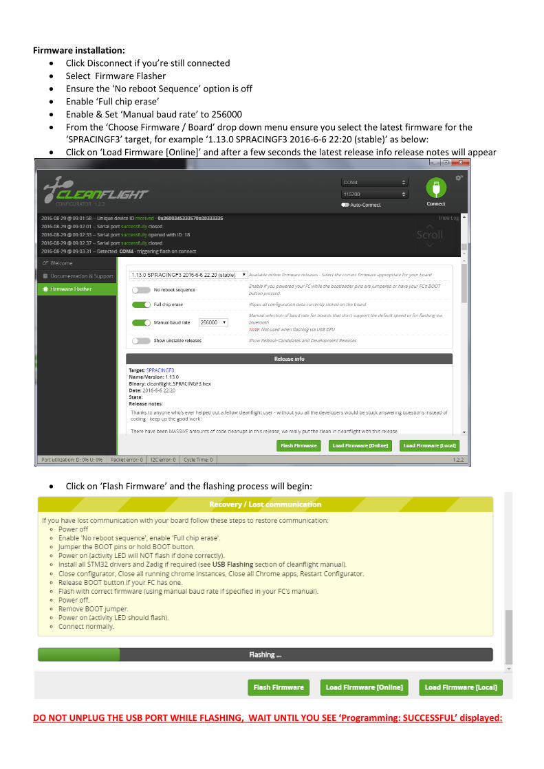
Firmware installation:
Click Disconnect if you’re still connected
Select Firmware Flasher
Ensure the ‘No reboot Sequence’ option is off
Enable ‘Full chip erase’
Enable & Set ‘Manual baud rate’ to 256000
From the ‘Choose Firmware / Board’ drop down menu ensure you select the latest firmware for the ‘SPRACINGF3’ target, for example ‘1.13.0 SPRACINGF3 2016-6-6 22:20 (stable)’ as below:
Click on ‘Load Firmware [Online]’ and after a few seconds the latest release info release notes will appear
Click on ‘Flash Firmware’ and the flashing process will begin:
DO NOT UNPLUG THE USB PORT WHILE FLASHING, WAIT UNTIL YOU SEE ‘Programming: SUCCESSFUL’ displayed:

Hardware Installation: For ease of installation we recommend you apply solder to all required headers and twist + tin all cables prior to soldering the wires to the PCB:

The following is a standard wiring installation for a typical FPV ‘X’ quadcopter, be sure to take note of the front ‘^’ arrow for correct board orientation:
When using soldered connections in high vibe environments using some form of wiring support is recommended near the solder joint to prevent fatigue:

Basic Cleanflight Setup: Once the FC is installed, REMOVE ALL PROPELLERS, power up your quadcopter, bind your receiver & connect to Cleanflight - the Setup page will come into view Accelerometer Calibration:
Place the quadcopter on a flat, level surface
On the Setup page, click the ‘Calibrate Accelerometer’ button & wait until process is completed
Pick the quad up and point it at your monitor. Click the ‘Reset Z axis’ button and ensure the 3d model mimics any movement of the quad you make (this ensures board orientation is correct)
Serial Port Configuration (Only for those using a Serial Rx and/or OSD):
Select the ‘Ports’ Tab.
If you’re using an SBUS or Spektrum based Serial receiver you must enable ‘Serial Rx’ on UART 3
If you plan to use a Minim OSD (not covered in this guide), you must also enable ‘MSP’ on UART2
Click ‘Save and Reboot’
Receiver Configuration:
Select the ‘Configuration’ tab
Scroll down to the ‘Receiver Mode’ box and select your applicable type (RX_SERIAL or RX_PPM)
If using a serial receiver, In the ‘Serial receiver Provider’ box you must select the appropriate receiver type
Click ‘Save and Reboot’
Select the ‘Receiver’ tab
Verify your RC Transmitter stick inputs are controlling the associated Roll/Pitch/Yaw/Throttle bars and in the correct direction (sticks left / down = lower number, up / right = higher number), If your inputs are controlling the wrong channel, change the channel map to suit – for example, to swap Roll/Yaw, AETR1234 becomes RETA1234. (R=Rudder or Yaw, E = Elevator or Pitch, T= Throttle and A = Aileron or Roll)
Use the subtrim on your RC Tx to ensure Roll/Pitch/Yaw channels are exactly 1500 when sticks are centred & 1000/2000 at maximum deflection.

If you can’t quite get your Pitch/Roll/Yaw inputs exactly 1500 after adjusting sub trims, we recommend adding some deadband equal to the amount of error in your sticks (2-4 is usually required with a Taranis + X4RSB)
Motor Setup:
Select the ‘Configuration’ tab
IF your ESC’s support it, enable ‘ONESHOT125’ in the ‘ESC/Motor features’ box
Select the ‘Motors’ Page
REMOVE ALL PROPELLERS
Connect the battery if it isn’t already
Enable Motor Test Mode
Click on the ‘Master’ slider once
Using the Arrow keys on your keyboard, use the up/down arrow to slowly increase the master slider until all motors start rotating consistently.
Add 10 to this value to get the value for ‘Min Throttle’ (for example in the picture below, all motors started rotating at 1045, were consistent at 1050 hence my Min Throttle would be 1060)
If all motors don’t start rotating within 5 units of each other than an ESC calibration is necessary – refer to your ESC’s manual.
Select the ‘Configuration’ tab
In the ‘ESC/Motor Features box’ Enter the Min Throttle value you just worked out
Set Max Throttle to 2000
Click on Save and Reboot.

Flight Mode Setup:
Select the ‘Modes’ tab
Click on ‘Add Range’ on both ‘ARM’ and ANGLE’ modes
Assign a switch on your radio to output on channel 5 (AUX 1 in CF)
Now when you move the switch you assigned the small green bar under the slider should also move.
Set the switch to the position where you want the quad to be armed and then drag the slider to cover the small green bar.
Repeat this process for Angle on channel 6 (AUX 2)
Click on Save and Reboot
Congratulations you are now ready to fly!