Embed Size (px)
Citation preview

FLIGHT CONTROLS
The flight controls can be operated manually and automatically. From the flight deck, all control surfaces are mechanically operated via rod-and-cable systems, except the electrically operated aileron trim tab. To augment pitch attitude stability, an augment pitch attitude stability system is installed. When the autopilot is engaged, ailerons, rudder, elevator, and elevator-trim tab are controlled automatically. Ailerons
The ailerons are operated manually from the captain’s and first officer’s control wheels. The ailerons are equipped with spring tabs and balance tabs. The balance tab at the RH aileron can be electrically operated as a trim tab. The aileron trim control panel is installed at the rear of the pedestal. Rudder
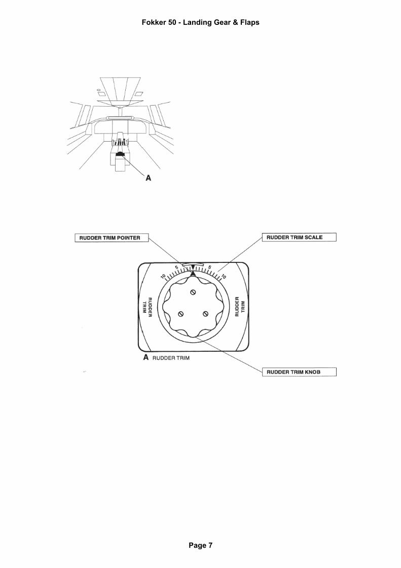
The rudder is operated manually from the captain’s and first officer’s pedals. A trim tab and a balance tab, one above the other, are attached to the trailing edge of the rudder. The trim tab can be operated mechanically from the trim control panel on the pedestal. Elevator
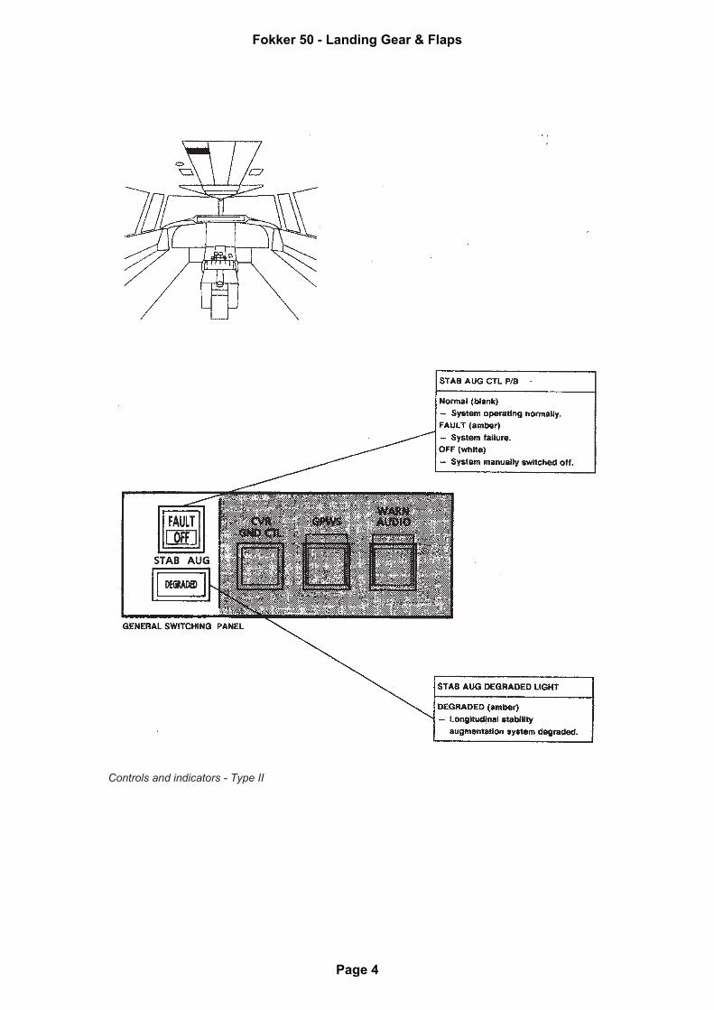
The elevators are operated manually from the captain’s and first officer’s control column. Pitch trim is obtained by an elevator trim tab at the RH elevator. The trim tab is operated by trim wheels on both sides of the pedestal. A position indicator near each control wheel shows the trim setting. Augment pitch attitude stability
There are two pitch stability systems:
• Elevator Feel Control System.
• Longitudinal Stability Augmentation System.
Type I
An automatic Elevator Feel Control System (EFCS) is provided to balance the out-of-trim forces caused by transients due to power and flap selections that would otherwise be felt at the control column. The system operation is automatic and is active only during flight. Flap and power lever positions are used as input variables. If the system fails, an alert will be presented. The fault annunciation due to the power levers and flaps is inhibited during flight, the alert will be presented on the ground approximately 15 seconds after landing. The system can be switched OFF with the AUTO EL FEEL CTL pushbutton at the general
Fokker 50 - Landing Gear & Flaps
Page 1
switching panel. Once switched OFF, the system cannot be reinstated from the flight deck. If the system is switched OFF, or has failed, the elevator operation is not affected. The elevator control forces will now be defined by the position in which the feel control unit ceased operation. On the ground an automatic self-test of the system is initiated when the flight control lock is engaged, and the system is placed into a parked condition. Type II
The Longitudinal Stability Augmentation System (LSAS) is provided to correct for the dynamic out of trim farces caused by changes in engine power, flap position and aircraft speed, and to augment the longitudinal stability at forward CG in flight. System operation is automatic and active during flight only. Inputs are provided by:
• Both Electronic Engine Control (ENG EC) units.
• Attitude and Heading Reference System no 1 (AHRS 1).
• Flap drive unit.
• Air Data Computer (ADC).
NOTE: For those aircraft equipped with two ADC’s, ADC 1 is used as input for this system.
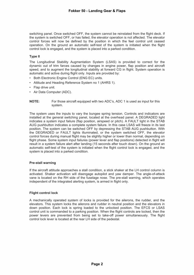
The system uses the inputs to vary the bungee spring tension. Controls and indicators are installed at the general switching panel, located at the overhead panel. A DEGRADED light indicates a system input failure (flap position, airspeed or pitch). A FAULT light in the STAB AUG pushbutton indicates a complete system failure. In this case LSAS will freeze in its last position. The system can be switched OFF by depressing the STAB AUG pushbutton. With the DEGRADED or FAULT lights illuminated, or the system switched OFF, the elevator control forces during manual flight may be slightly higher or lower than normal, depending on flight phase. Some system input failures (power lever and flap positions) detected in flight will result in a system failure alert after landing (15 seconds after touch down). On the ground an automatic self-test of the system is initiated when the flight control lock is engaged, and the system is placed into a parked condition. Pre-stall warning
If the aircraft attitude approaches a stall condition, a stick shaker at the LH control column is activated. Shaker activation will disengage autopilot and yaw damper. The angle-of-attack vane is located on the RH side of the fuselage nose. The pre-stall warning, which operates independent of the integrated alerting system, is armed in flight only. Flight control lock
A mechanically operated system of locks is provided for the ailerons, the rudder, and the elevators. This system locks the ailerons and rudder in neutral position and the elevators in down position. Each lock is spring loaded to the unlocked position. The EFCS or LSAS control unit is commanded to a parking position. When the flight controls are locked, then the power levers are prevented from being set to take-off power simultaneously. The flight control lock lever is located at the rear LH side of the pedestal.
Fokker 50 - Landing Gear & Flaps
Page 2

Controls and indicators
Controls and indicators - Type I
Fokker 50 - Landing Gear & Flaps
Page 3
Controls and indicators - Type II
Fokker 50 - Landing Gear & Flaps
Page 4
Controls and indicators - Type I
Fokker 50 - Landing Gear & Flaps
Page 5
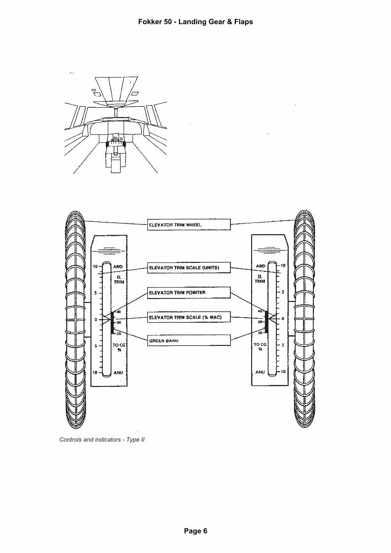
Controls and indicators - Type II
Fokker 50 - Landing Gear & Flaps
Page 6
Fokker 50 - Landing Gear & Flaps
Page 7
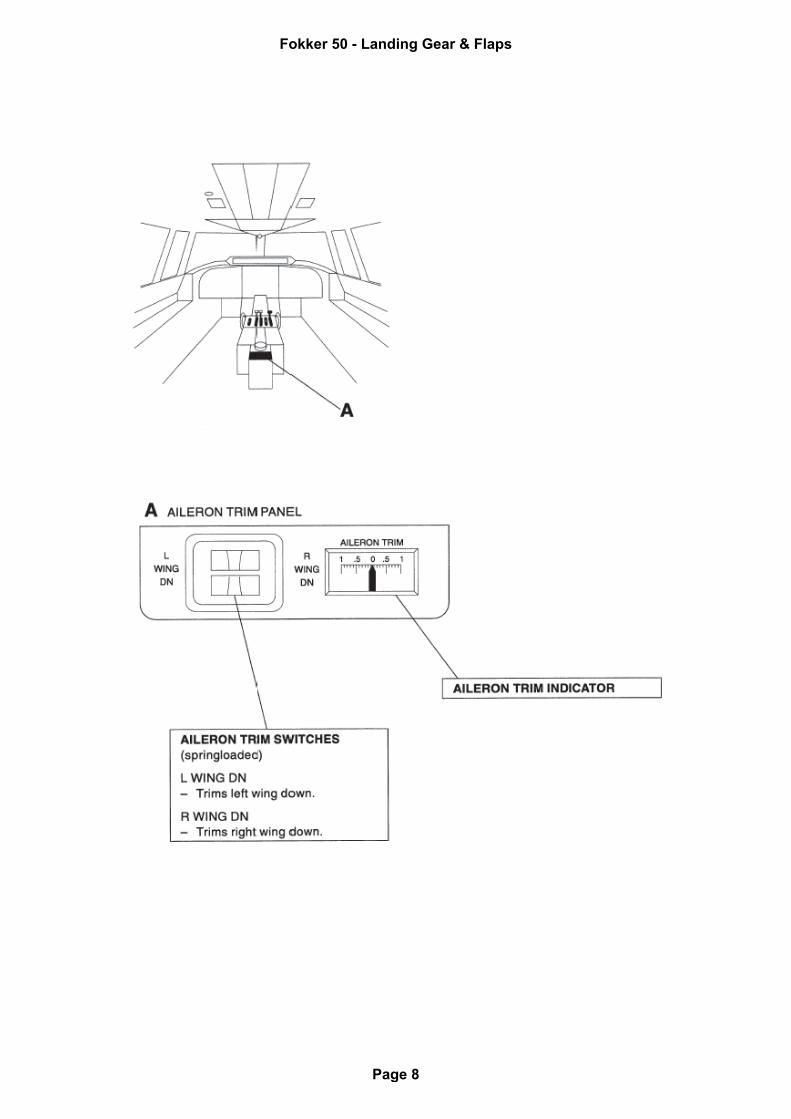
Fokker 50 - Landing Gear & Flaps
Page 8
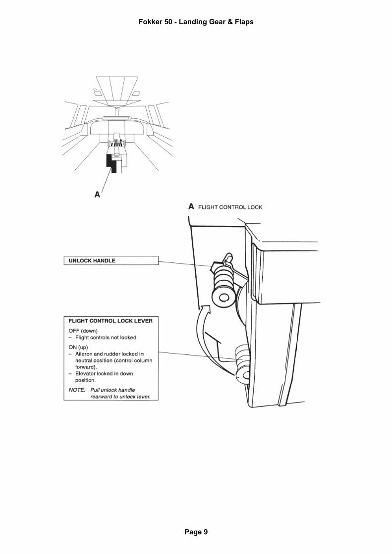
Fokker 50 - Landing Gear & Flaps
Page 9
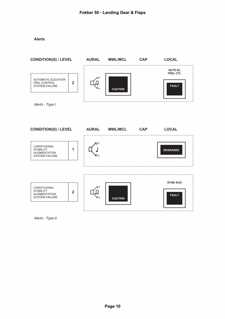
Alerts
Alerts - Type I Alerts - Type II
AUTOMATIC ELEVATOR FEEL CONTROL SYSTEM FAILURE
2
AURAL MWL/MCL CAP LOCAL CONDITION(S) / LEVEL
CAUTION
FAULT
AUTO EL
FEEL CTL
LONGITUDINAL STABILITY AUGMENTATION SYSTEM FAILURE
2
CAUTION
FAULT
STAB AUG
LONGITUDINAL STABILITY AUGMENTATION SYSTEM FAILURE
1
AURAL MWL/MCL CAP LOCAL CONDITION(S) / LEVEL
DEGRADED
Fokker 50 - Landing Gear & Flaps
Page 10
FLAPS
Operation
The flaps can be controlled by a seven position flap selector (UP, 5, 10, 15, 20, 25, 35). The mechanically operated flap selector valve directs hydraulic pressure to the flap drive unit in accordance with flap selector position. The position of the flaps is indicated by a flap position indicator located at the center main instrument panel. Position markings are located at the inboard side of the engine nacelles. A disagreement light illuminates when flap position is not in accordance with flap selector position. The alert is inhibited during the period when the flaps are in transit. Alternate operation
Adjacent to the flap selector is an alternate flap control switch that operates the flap drive unit electrically. The travel range is the same as in the hydraulic mode; however, the flaps extend at a slower rate. After alternate operation, no hydraulic operation can be made before the system is reset. Reset is obtained on the ground by moving the flap selector to an other position. Asymmetry protection
LH and RH flap positions are continuously compared and when an angular difference is detected an alert is presented. When asymmetry is detected during hydraulic operation, further flap movement is stopped.
Fokker 50 - Landing Gear & Flaps
Page 11

Functional diagram
Fokker 50 - Landing Gear & Flaps
Page 12

Controls and indicators
Fokker 50 - Landing Gear & Flaps
Page 13

Alerts
FLAP DISAGREMENT
2
AURAL MWL/MCL CAP LOCAL CONDITION(S) / LEVEL
CAUTION
FLAP
FLAP ASYMMETRY
2
CAUTION
FLAP ASYM
Fokker 50 - Landing Gear & Flaps
Page 14
TAKE-OFF CONFIGURATION WARNING
Description
With the aircraft on the ground and either power lever in TO position, the TO CONF light at the CAP illuminates when one of the following conditions is met:
• Elevator trim not in TO position.
• Rudder trim not in TO position.
• Flaps not in TO position.
• Parking brake not released.
• Neither TO nor FLX nor GA selected at the engine rating panel. See OM Part B section POWER PLANT.
• Propeller autofeather system not armed. See OM Part B section POWER PLANT. NOTE: The alerts cannot be cancelled by depressing MWL. With the aircraft on the ground and either power lever not in TO position, the take-off configuration can be tested by depressing the TO CONFIG button at the test panel for at least 2 seconds. The TO CONF light at the CAP remains out when the take-off configuration is complete. NOTE: The test can be performed with the parking brake on.
Fokker 50 - Landing Gear & Flaps
Page 15
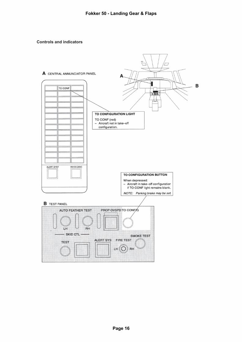
Controls and indicators
Fokker 50 - Landing Gear & Flaps
Page 16
Alerts
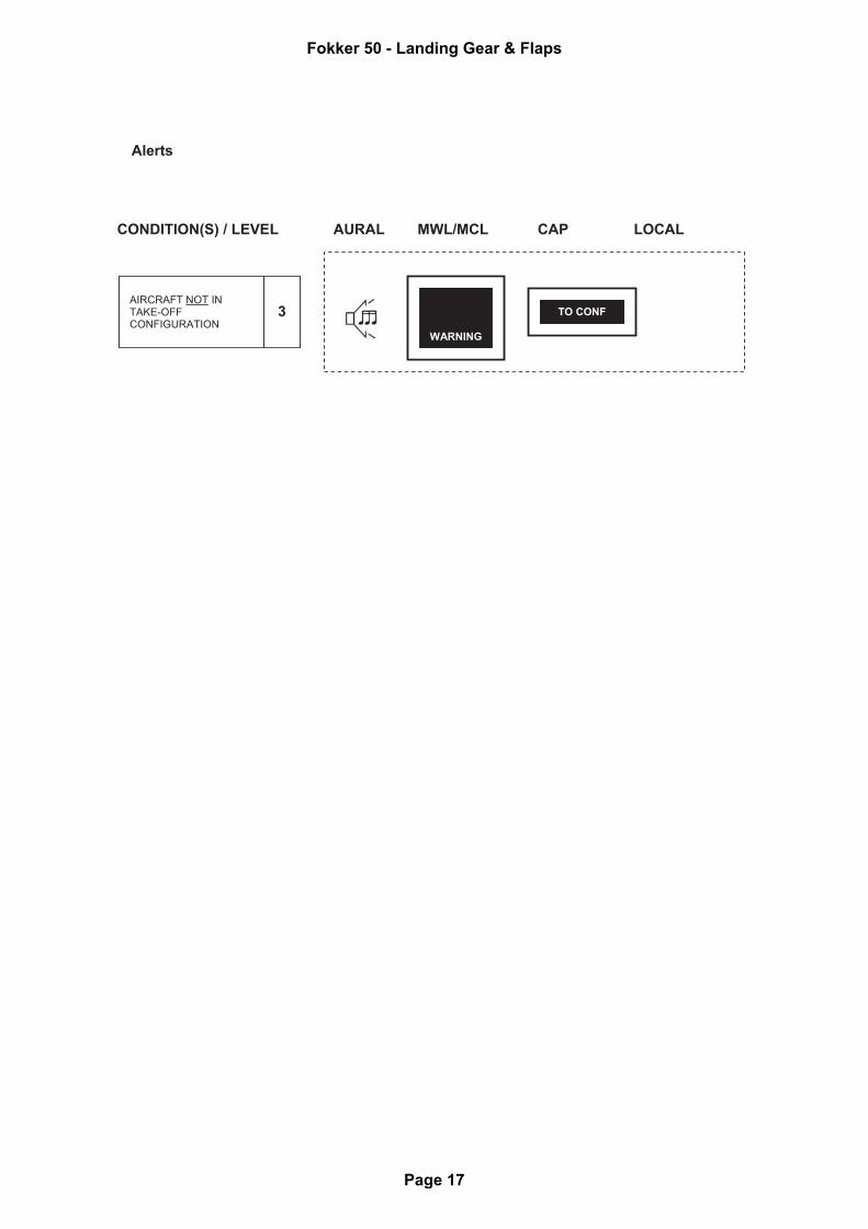
AIRCRAFT NOT IN TAKE-OFF CONFIGURATION
3
AURAL MWL/MCL CAP LOCAL CONDITION(S) / LEVEL
WARNING
TO CONF
Fokker 50 - Landing Gear & Flaps
Page 17

SYSTEM OPERATION
Flight control lock
The flight-control lock should be engaged during taxiing and parking. After setting the flight-control lock, move the control column slightly forward and bring the ailerons and rudder to the neutral position; check the flight controls are locked. When releasing the lock, be aware of flight control movement due to wind. The PF should keep his feet on the rudder bar while the PNF should hold the control wheel. CAUTION: Applicable for aircraft equipped with LSAS. If the flight control lock is engaged
while the flaps are traveling the system will see this as a wrong input during the test phase of the LSAS, this might cause a non reset-able FAULT of the LSAS.
Flaps
Normal operation
The flaps are hydraulically operated and the flap position is controlled by a flap selector. Operating time from up (0) to 35 or reverse is approximately 15 seconds. Alternate operation
The flaps are electrically operated and controlled by the alternate flap control switch. Alternate flap operation inhibits normal flap selection. To avoid nuisance alerts select the normal flap selector to the indicated flap position. Operating time from up (0) to 35 or reverse is approximately 180 seconds.
Fokker 50 - Landing Gear & Flaps
Page 18

![Flight Controls - SmartCockpit - Airline training guides ... · PDF fileAirbus A319-320-321 [Flight Controls] Page 100. Airbus A319-320-321 [Flight Controls] Page 101. Airbus A319-320-321](https://img.pdfslide.net/doc/110x75/5aa53a387f8b9a185d8d0880/flight-controls-smartcockpit-airline-training-guides-a319-320-321-flight.jpg)


![EMBRAER 190 - SmartCockpit · Embraer 190 - Systems Summary [Automatic Flight Control System] Page 16. The autopilot disengages when any of the following conditions occur :](https://img.pdfslide.net/doc/110x75/5ae1d8977f8b9a7b218b4576/embraer-190-190-systems-summary-automatic-flight-control-system-page-16-the.jpg)