Embed Size (px)
Citation preview
Flight Dynamics Analysis Branch
End of Fiscal Year 1999 Report
October 1999
Goddard Space Flight Center
Flight Dynamics Analysis Branch/Code 572
Greenbelt, Maryland 20771
https://ntrs.nasa.gov/search.jsp?R=20000024884 2018-07-03T19:04:48+00:00Z

w
9-9-99
FLIGHT DYNAMICS ANALYSIS BRANCHEND OF FISCAL YEAR 1999 REPORT
(*** DRAFT since 8/11/99)
October 1999
Goddard Space Flight Center
Flight Dynamics Analysis Branch/Code 572Greenbelt, MD 20771
Preface
The contents of this report are based on inputs generously supplied by members of the Flight Dynamics
Analysis Branch (FDAB), a sub-division of the Guidance, Navigation, and Control Center (GNCC), atNASA/Goddard Space Flight Center (GSFC).
The primary authors of this report are:
Tom Stengle, Head, Flight Dynamics Analysis Branch, Code 572
Felipe Flores-Amaya, Flight Dynamics Analysis Branch, Code 572
Additional information concerning FDAB activities may be obtained through the following Branch
management:John P. Lynch, Associate Head, Flight Dynamics Analysis Branch, Code 572Karen Richon, Associate Head, Flight Dynamics Analysis Branch, Code 572
Published copies of this report will be available from:Catherine A. Waltersdorff
Flight Dynamics Analysis BranchCode 572
NASA/Goddard Space Flight CenterGreenbelt, MD 20771
A Hypertext Markup Language (HTML) version of this document will be available on the Intemet WorldWide Web in the Uniform Resource Locator (URL):http://aetd.gsfc.nasa.gov/gncc/branches/fdab/FDAB_EOFY99.html.

! 1
°
TABLE OF CONTENTS
INTRODUCTION ....................................................................................... I-1
2 MISSION OPERATIONS SUPPORT ............................................................. .'...2-1
EO-1 ................................................................................................................... 2-
EOS AM-1 ............................................................................................................. 2-EOS PM ................................................................................................................ 2-
ERBS ................................................................................................................... 2-
FUSE ................................................................................................................... 2-GOES ................................................................................................................... 2-
IMAGE ................................................................................................................ 2-
InFocus (ULDB) ...................................................................................................... 2-Landsat-7 ............................................................................................................... 2-
Lunar Prospector ...................................................................................................... 2-MAP ................................................................................................................... ;.2-
Spartan ................................................................................................................... 2-Triana .................................................................................................................... 2-TRMM ................................................................................................................... 2-
MISSION ANALYSIS ....................................................................................... 3-1
Advanced Mission Design ............................................................................................. 3-
Autonomous Relative Navigation & Formation Flying ............................................................ 3-Advances in Navigation Technology .................................................................................. 3-
Global Positioning System (GPS) Orbit Determination ............................................................. 3-"Compound Eye" GPS Attitude and Navigation Sensor ........................................................... 3-
Autonomous Navigation ................................................................................................ 3-Navigation Studies ........................................................................................................ 3-
FUTURE MISSIONS ANALYSIS ........................................................................ 4-1
IMDC ................................................................................................................... 4-1
Mission Concept Support ............................................................................................. 4-
ATTITUDE DETERMINATION .............................. 5-1
Advanced Attitude Determination and Calibration ................................................................ 5-
Attitude Models Task .................................................................................................. 5-
Magnetometer Navigation ............................................................................................. 5-WIRE ..................................................................................................................... 5-
FLIGHT DYNAMICS DATA LAB ........................................................................ 6-1
Flight Dynamics Data Lab .......................................................................................... 6-I
INTERAGENCY ACTIVITIES ......................................................................... 7-1
CCSDS .................................................................................................................. 7-1
Flight Mechanics Symposium .............................................................................. • ......... 7-1
ISO ............................................................................................................ 8-I
APPENDIX A ....................................................................................................... A-i

APPENDIX B ......................................................................................................... B- 1
1.0 Introduction
This document summarizes the major activities and accomplishments carried out by the Goddard Space
Flight Center (GSFC)'s Flight Dynamics Analysis Branch (FDAB), Code 572, in support of flight projectsand technology development initiatives in Fiscal Year (FY) 1999. The document is intended to serve asboth an introduction to the type of support carried out by the FDAB, as well as a concise reference
summarizing key analysis results and mission experience derived from the various mission support rolesassumed over the past year.
The major accomplishments in the FDAB in FY99 were:
Provided flight dynamics support to the Lunar Prospector and TRIANA missions, among a variety of
spacecraft missionsSponsored the Flight Mechanics Symposium
Supported the Consultative Committee for Space Data Systems (CCSDS) workshopsPerformed numerous analyses and studies for future missions
Started the Flight Dynamics Analysis Branch Lab for in-house mission analysis and supportComplied with all requirements in support of GSFC ISO9000 certification
2.0 Mission Operations Support
2.1 EO-I Earth Observing- 1
Earth Observing - I, the first spacecraft in the New Millennium Program, is scheduled for launch in mid-December, 1999. The GNCC has multiple interests in the successful launch and operations of EO-1.
Initially, EO-1 was solely a satellite to showcase more than 10 new and largely separate technologies. Theforemost new technology was the Advanced Land Imager (ALl), which was intended as the next generation
Landsat-type imager. The primary mission was designed to fly EO- 1 one minute along track behindLandsat-7 and take the same image that Landsat-7 has just taken for comparison. The ALI detectors are
located such that they cover the easternmost 1/5 of the Landsat-7 swath. There is also a cross track
requirement of +/- 3 km. which keeps the ALI detectors in the desired portion of the Landsat-7 swath. Asecond instrument, the GSFC Atmospheric Corrector(AC), was designed to operate with the ALI. About
one year before launch, a companion instrument to the ALI and the AC, TRW's Hyperion instrument, wasadded to the spacecraft. This additional imager was to have flown on the failed Lewis spacecraft and will
image a narrow swath that includes the westernmost 1/5 of the ALI swath.
Another GNCC based technology is the Pulsed Plasma Thruster designed for attitude pitch control.
Currently, the validation of this technology will occur after the prime imaging mission is completed.
The GNCC has played a major role in designing and implementing the EO-1 Flight Dynamics SupportSystem (FDSS) which will provide Flight Dynamics support entirely within the EO- 1 Mission Operations
Center (MOC). After the first 60 days, Flight Operations Team (TOT) personnel will perform the entire
Flight Dynamics function within the MOC. During the first 60 days, GNCC personnel will the ascent andcheckout phases of the mission. GNCC personnel must design the FDSS operational procedures and train
the FOT to achieve operational expertise with the FDSS. There are four major areas of Flight Dynamicssupport for EO-I. They are: attitude validation and calibration, orbit determination, orbit maneuvercontrol and orbit and attitude products generation. Most of these functions are supported with COTS based
software that has been adapted to meet EO-1 FDSS requirements. Approximately 60 percent of the FDSS
EO-1 procedures will be executed via automation. This will reduce the execution time of certain FDSStasks by a factor of 10.
The orbit maneuver control function showcases a major GNCC accomplishment. One on the EO-Itechnologies is Enhanced Formation Flying (EFF), which has the goal of autonomous on board orbit
maneuver control. The FDSS will provide a ground-based EFF tool, AUTOCON-G, to validate the on
board EFF algorithms. After the first few months of ground-based EFF operations, designed to keep EO-Iin the strict formation with Landsat-7, the on board EFF software, AUTOCON-F, will be designated as
prime with the ground as a backup. The orbit and attitude product generation capabilities in the FDSSprovide about three dozen products that aid in spacecraft health and safety maintenance, command
generation in the MOC and image planning for the groups that built the ALl, AC and Hyperioninstruments.
The FDSS has had all planned software releases delivered as of 7/31/99 and FDSS mission procedures arebeing written with 10/1/99 targeted as the completion date. The last four months before launch will includeextensive simulations of the entire EO-I ground system including the FDSS. To date spacecraft integration
and testing problems have delayed most ground system proficiency testing and simulations. The last
quarter before launch will be one of the busiest in recent memory.
Finally, the GNCC has provided extensive mission analysis support to the EO- I Project in the areas of
trajectory and launch window computations for launch vehicle support, ascent maneuver planning to aid inLaunch & Early Orbit timeline planning and product generation to support spacecraft and ground systemIntegration & Test activities.
[Technical contacts: Robert L. DeFazio/572; Richard J. Luquette/572]

2.2 EOS AM-I Earth Observing System Terra
The EOS Terra spacecraft, formerly known as EOS AM-1, is currently in the final stages of preparation for
launch from Vandenburg Air Force Base. Launch delays due to spacecraft hardware and mission operation
center software modifications, as well as a recent investigation of the Atlas IIAS upper stage rocket, haspostponed the scheduled launch into the first quarter of FY 2000. GN&C activities during the pre-launch
phase included a successful completion of the comprehensive performance test (CPT), a delivery ofinjection targets to the Lockheed Martin/Atlas team, as well as participation in various launch and earlyorbit and routine operations simulations.
GN&C testing in August 1998 resulted in the discovery of a voltage leakage condition in the AttitudeControl Electronics (ACE) hardware. Specifically, it was found that an input signal that was outside the
voltage range of the ACE Safe Hold Digital Processor analog MUX resulted in leakage into the other MUXchannels. Input to the MUX consists of position, rate and magnetometer signals. The redundant ACE
hardware was removed from the spacecraft to install zener diodes in order to limit the MUX input signals.The ACE was successfully reintegrated onto the spacecraft in January 1999.
In addition, the Flight Dynamics System was tested and enhanced throughout the year to meet changing
mission requirements. An automation system, autoProducts, was implemented as a front end to the FDS.autoProducts allows a non-expert user to access all of the COTS and GOTS software that comprises the
FDS through a common user interface, changing only those parameters necessary to generate planningproducts. The system significantly simplifies the process of generating the 85 required products from
several different pieces of software, as well as minimizing chances for user errors.
[Technical contact: Lauri Newman/572]
2.3 EOS PM-1 Earth Observing System PM-1
EOS PM- I Mission -- Completed Flight Dynamics System (FDS) support requirements definition through
meetings with the Project representatives, Flight Operations Team (FOT) members, and the PrincipalInvestigators (PIs) for each instrument. Provided FDS inputs to the Mission Support Requirements
Document (MSRD) based on the meetings and drafted Interface Control Documents (ICDs) for each entity.Performed orbit determination error analysis, contact requirements analysis, launch window/maneuveranalysis, and provided preliminary inputs for attitude sensor calibration plan. Negotiated attitude sensor
telemetry requirements with the spacecraft vendor. Supported Project-level meetings with the spacecraf_vendor, PIs, and other Goddard mission interfaces.
[Technical contact: David Tracewell/572]
2.4 ERBS Earth Radiation Budget Satellite
The ERBS spacecraft, which was launched in 1984, experienced an under-voltage condition on battery #2due to cell failures. This failure, which occurred on January 16, 1999, caused the ACS to autonomously
enter the B-Dot mode. Note that this was the first time that ERBS ACS had ever autonomously entered
B-Dot mode. Following the successful commanding of the spacecraft back to normal ACS pointing mode,a full scale effort was made in order to recondition battery #1, which was disconnected in 1993 due its owncell failures. Resolution of this anomaly has returned ERBS to a safe power configuration, thereby
enabling the ACS to provide the required attitude pointing as well as the periodic 180 degree yawmaneuvers. This has allowed for the resumption of science gathering activities.
[Technical contact: Samuel J. Placanica/572]
2.5 GOES-L Geostationary Operational Environmental Satellite
The GOES-L spacecraft is the fourth of a five spacecraft series built by Space Systems / Loral and placed
on station by a GSFC Flight Operations Team (FOT) supported by GNCC and Computer SciencesCorporation Flight Dynamics personnel. The first three spacecraft in the series were launched on an Atlas I
launch vehicle (L/V). After that L/V series was phased out, the remaining spacecraft were manifested onan Atlas IIA. This later LN had significantly more performance than the Atlas I, which allowed a transfer
orbit redesign leading to more mission lifetime. That was the good news. On the reverse side, getting a
firm manifest slot on the Atlas IIA has been a disaster. Our Flight Dynamics team planned no less than 7mission profiles for GOES-L ranging over the time period from January to June, 1999. Finally, we had afirm launch slot on May 15, 1999, had our Flight Dynamics team well trained and got to within 1 month of
launch. Then, the Atlas IIA, along with several other launch vehicles, experienced a very serious RL-I0
engine problem on its Centaur stage. The launch of GOES-L was postponed indeffmitely while the FOTand the Flight Dynamics team tries to remain intact and ready to support. The GOES Project attempts to
sustain operational readiness by holding monthly simulations and proficiency testing until a firm launchdate is selected. The best estimate foi" a launch of GOES-L, as of mid-August 1999, is sometime in the first
quarter of 2000.
[Technical contact: Robert L. DeFazio/572]
2.6 InFocus Mission
The InFocus telescope is a 9 meter long X-ray telescope being developed at GSFC for flight on a high
altitude (40 km) stratospheric balloon. Whereas most pointed instruments on balloons use anazimuth/elevation system, InFocus is aiming to achieve arcsecond level pointing performance using a
single cup/bali oil filled bearing between the pointed and non-pointed sections of the gondola. With thisrotational isolation the pointed section, consisting of the telescope and support subsystems, is able to be
controlled similarly to an orbiting pointed payload, using reaction wheels, magnetic torquers, startrackers
and gyros.
Analysis is underway, to specify critical control elements in the pointing control system via simulation and
analysis. The complicated pendulous dynamics of the load train (connecting the balloon and gondola) dueto aerodynamic loads are being studied to insure that disturbances to the pointed section due to unbalances
about the ball center are adequately controlled.
To this end, a demonstration flight within the next year to measure disturbances will be flown. Notelescope will be on this flight. A second flight will carry the Infocus telescope using the standard azimuth
elevation pointing system. The final flight and third will incorporate the ball/cup design and is anticipatedin two years.
Additionally, work is underway to recommend changes to the design of the balloon train for all pointedpayloads to minimize dynamic effects particularly on azimuth elevation systems. Depending on analysis
results there could be a fourth flight to qualify a newer train design.
The analysis required for all flights is being provided by the FDAB.
The telescope is about 9 meters in length. Unlike most balloon pointed payloads using anazimuth/elevation pointing system, InFocus will use a single oil-filled ball/cup mechanical interface
between the pointed element and the to mechanically mount
[Techhical contact: David Olney/572]

[Technicalcontact:Sue l-lt?_e/572]
2.8 Lunar Prospector
Lunar Prospector (LP) completed its primary mission on December 31, 1998. The LPExtended Mission was authorized for six-months and included a lower altitude above the lunar surface. On
January 19, 1999, GNCC planned the maneuvers to lower the altitude to a mean of 40 km. After one
month, the altitude was again lowered to a mean of 30 km. GNCC planned all spacecraft maneuvers,including monthly maintenance maneuvers required to keep LP in its orbit. GNCC also performed all orbit
determination including maintaining a web site with all LP definitive ephemerides (fdd.gsfc.nasa.gov/lp)for instant access by mission controllers or PIs. On July 30, 1999, the first of two final maneuvers wasperformed to raise apoapsis to target the final impact of LP into a permanently shadowed crater on the lunar
southern pole. On July 31, 1999, LPs final maneuver was performed on the dark side of the Moon and LP
was never heard from again. GNCC provided complete flight dynamics support to the operations center atAmes Research Center. As part of targeting the final impact, improved lunar topography was needed.
GNCC worked with ARC, University of Texas, GSFC Code 900, and the Smithsonian to obtain the bestestimates of lunar topography around the impact site. All indications are that the impact was on target.
Analysis of the final impact and the determination of water content is still ongoing.
[Technical contact: Mark Beckman/572]
2.9 SPARTAN
Spartan 201-5
The Spartan 201-5 solar physics mission was launched on STS-95 October 29, 1998. It was deployedOctober 31 and successfully completed its 9 day mission for the Solar Astronomical Observatory (SAO)
before being retrieved and returned to earth. The Flight Dynamics and Analysis Branch supported themission by determining the desired deploy orientation and computing the remote adjust values to be entered
by the shuttle crew immediately before deploy.
Spartan 250
The Spartan 250 series of spacecraft is planned to be an upgrade of the existing Spartan 200 series. It isdesigned for better performance and increased mission lifetime. It will have a Power PC CPU based digital
attitude determination and control system and an RF communication capability.
The Spartan 251 missions will carry an experimental micro-satellite mission for the Air Force.
Preparations for the Spartan 251/XSS-10 mission were stopped in May when it was determined that themission would not be manifested within a timeframe acceptable to the Air Force. The XSS-I 0 mission willnow be flown on an expendable launch vehicle, without the Spartan carrier. Before work was halted the
digital ACS, onboard environmental models, and dynamic simulator algorithms had been fully developedand tested, and were being transferred to flight software.
We are now working on the Spartan 251/XSS-11 mission which is scheduled for launch in the 2002-2003
timeframe. Only slight modifications to the existing Spartan 25 i/XSS-10 ACS algorithms described abovewill be required to support this mission. The design lifetime for this mission will be greater than the XSS-
10 mission we will probably go from cold gas thruster actuators to reaction wheels. If this is the case wewill require further modifications to the ACS algorithms and more simulations. The LN200 gyro has been
baselined for all the Spartan 250 missions and preparations for an LN200 gyro test bench are being made.This will include preparing an ICD for the gyro that will be used during spacecraft integration.
Spartan Lite

TheSpartanProjecthasdiscontinuedproposalworkontheSpartanLitespacecraft.ItwasdeterminedthattheneedforsmallspacecraftbusesofthissortisbeingadequatelymetbyindustrysothefocusisnowonSpartan250andSpartan400spacecraft.
Spa_an400
Spartan400isSpartanproject'snewestproposal.Thiscarrierwillextendthemissionlifefrom12daysofSpartan200seriesto12months.It isshuttlelaunchedandwillbeabletohouselargeinstrument(1meterplusand2000pounds).Sincethecarrierandtheinstrumentareretrievable,it providesthespaceindustrytheabilitytoobtainsciencequickly,inexpensivelyandatalowerrisk.
Spartan401isanearthpointerwithhalfadozeninstrumentonboard,includingLIDAR,STW/AR,SHIMMER,GPSOS,OOAM,StOLSS.LIDARisnadirpointing;STW/ARincludes6antennaspointedtowardsnadir;SHIMMERpointstowardslimbandincludeslimitedlunartrack;GPSOSincludes3largeantennaswithspecificorientations;OOAMisalimbpointertrackssunriseandsunsetwithmovableoptics;StOLSSisa limbpointerrequiresunobstructedFOV.Therequiredorbitis450x450km;thedesiredorbitis600x 600km.Inclinationis51.6degrees.Theattitudeandpointingcontrolaccuracyandknowledgevaries.ThefirsttaskforACSanalysisteamwastodevelopmentanerrorbudgetboundingtheperformancecapabilitybasedontheselectedsensorsandactuatorsforSpartan400series.Theanalyticresultswereverifiedwithsimulations.BasedontheanalysisresultsweprovidedACSimposedrequirementsontheothersubsystem,suchasopticalbenchthermalwarping,solararraythermalsnap,etc.Groundtrackingover+/-30degreeswasalsostudied.TheACSanalysisteamalsoheavilyinvolvedinthesolararraydesigntoensureitsorientationisattitudecontrolfavorable,byinvestigatingtheaerodynamictorqueanditseffectonwheelsandtorquerssizingforeachconfiguration.Inadditiontotheanalysis,ACSanalystsalsoparticipatedin thedevelopmentoftheproductdevelopmentplanintheareaofcoordinationsystemsdefinition,controlmodesandperformancespecification,ACSderivedrequirementdefinitionsandhardwarespecifications.
Spartan402isanadvancedsolarcoronalmissionwithtwocoalignedinstruments:spectroscopicandpolarimetriccoronagraph(SPC)mountedtoacentralmountingplate(CMP).A 10meterlongdeployablemastalsomounttoCMP,positionanexternalocculterassembly10metersforwardoftheSPCaperture.Spartan402willbedeployedat300kmattitudewith28-57degreeinclinationandraisedto580km.Becausethe10-meterlongboonhasasignificantmassatthetip,ACSanalysisteamperformedstabilityanalysisandthetipmassdeflectioneffectonthespacecraftattitudeperformance.ACSanalystsalsoassistedthestructureandinstrumentteamindefiningthedesignrequirementoftheboonintermsofstructurefrequency,dampingratioandmodalgain.InadditiontotheconventionalattitudesensorsfortheSpartan400series,thet-meattitudeisfromtheinstrumentGuideTelescope(GT)withfinesteeringmechanismthathasan8.5x 8.5arc-minutefieldofview.SincethisGTisflownonTRACE,theGTFOVsearchingalgorithmcanbeadopted.However,detailederrorbudgetwasneededforthefinesunacquisitiontoensuretheGNC'scapabilitytolocatethesunwithintheFOVoftheTRACEguidetelescope/ISS.Theanalyticalerrorbudgetresultwascrossedcheckedwithasimulation.Additionally,analystsparticipatedinthedevelopmentoftheProductDevelopmentPlanintheareaof coordinationsystemsdefinition,controlmodesandperformancespecifications,ACSderivedrequirementdefinitionsandhardwarespecifications.Spartan402proposalwassubmittedinJulyandanoralreviewwillbeheldonAugust19.
[Technicalcontacts:Josephine San/572; 5[m Morrissey/572]
2.10 TRIANA
The past year has been an incredible challenge for the Triana Attitude Control System (ACS) Analysisteam. This is a project with a very tight schedule. The baseline design, SMEX-lite, a protoflight spacecraft
designed in-house, was conceived for low earth orbiting spacecraft. The ACS system required extensive
modifications to accommodate a mission to the LI libration point. Working in a concurrent engineeringenvironment, the team is continually challenged to respond to constantly changing requirements. To
mitigate the requirements creep, the team created a flexible design capable of accommodating the
observatory'sevolvingrequirements.WehavesuccessfullycompletedcontrolsystemanalysisfortheTriana ACS, to the satisfaction of the Triana project.
All of the on-board controllers have been designed and simulated, proving our performance meets our
requirements. Work is currently underway to support software implementation of our controller design.
the same time, the team is preparing to support in-house integration and testing of the Triana spacecraft,beginning in the fall of 1999.
At
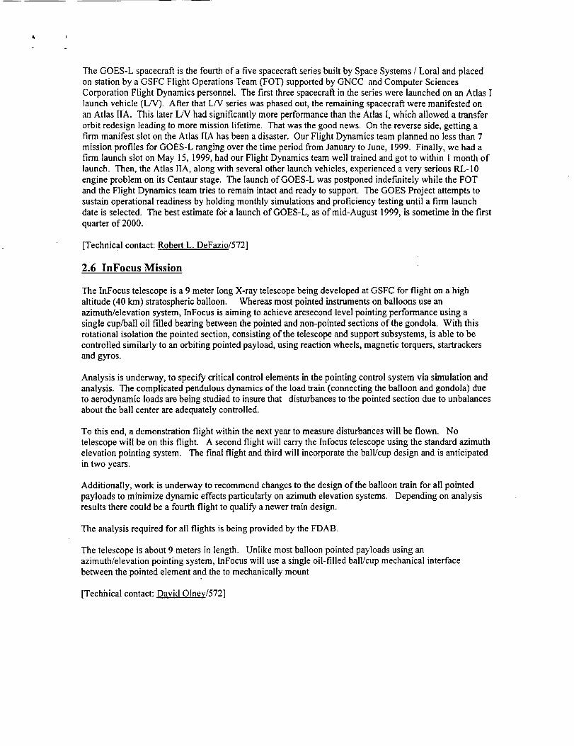
Triana is the latest mission planned to visit the Earth-Sun libration point. From L1, Triana will have a full-disk, sunlit view of the Earth at all times. Triana will provide pictures of the full sunlit Earth on the internet
every 15 minutes. FDAB took Triana from a mission concept to a mature mission design in just a few
months. FDAB worked with Triana PIs to alter the baseline mission trajectory to better meet scienceobjectives. The current mission includes a Lissajous orbit about LI, a shorter transfer time to LI and
improved Sun-Earth-Vehicle angles. The baseline trajectory is the first Lissajous orbit to be designed usingDynamical Systems Theory (DST) from Purdue University. DST is an analytic approximation of classes of
orbits that intersect L 1 and the Earth. DST greatly improves the efficiency of the mission design processand the fuel-efficiency of the trajectory design. FDAB worked closely with ACS and propulsion engineersto design an ACS and propulsion system that would meet mission requirements. This included number and
placement of spacecraft thrusters, fuel tank sizing and attitude modes. FDAB worked closely with JSC on
Space Shuttle launch and deployement scheduling. Triana requires four deployment opportunities for anylaunch time, with a crew sleep cycle in between, and within ground station coverage.
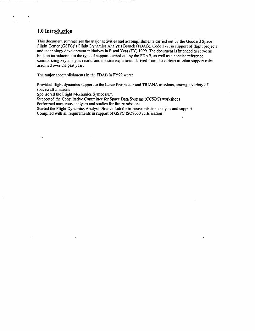
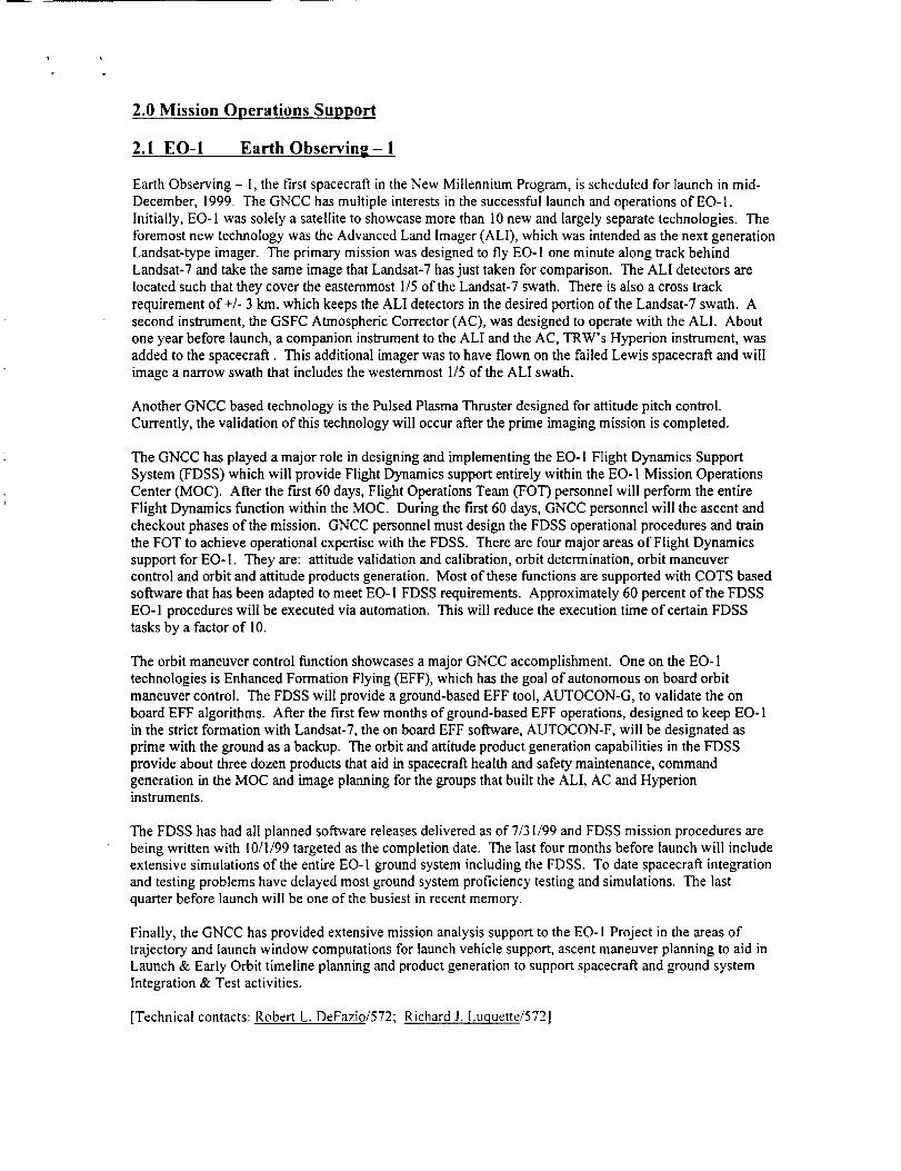
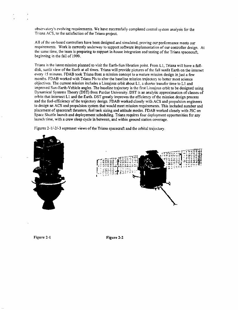
Figures 2-1/-2/-3 represent views of the Triana spacecraft and the orbital trajectory.
Figure 2-1 Figure 2-2

Figure2-3
For complete details about the TRIANA mission refer to htlp://triana.gsfc.nasa.gov/home/
[Technical contacts: Wen@ Morgenstern/572; MarkBeckman/572]
2.11 TRMM Tropical Rainfall Measuring Mission
The TRMM ACS has been successfully providing the required performance with respect to attitude
pointing and maneuver capabilities throughout Fiscal Year 1999. This includes the periodic 180 degreeyaw maneuvers to maintain thermal constraints, as well as orbit-raising maneuvers using thrusters in orderto keep the spacecraft at its 350 km orbit altitude.
During Fiscal Year 1999 a number of spacecraft issues required attention. The first of these issues was that
the drive for the minus Y solar array had been experiencing temperatures above the qualified test levels
since early mission operations. These high temperatures could result in a failure of the array drive, therebystopping the array. This situation would create a larger-than-designed-for aerodynamic torque environmentwhich would result in higher momentum unloading requirements for the ACS. The failure would also
effect the capability of the power subsystem. A long-term study was undertaken by various spacecraftsubsystems, including ACS, to see what could be done. The first action of the study was to reduce the
range of motion for the arrays in order to decrease the integrated angular motion for the minus Y arraydrive. The study then investigated the possibility of"parking" the minus Y array at an angle that would
satisfy power requirements with the least amount of impact to the ACS with regards to attitude pointing andmomentum unloading. Parking the minus Y array at an angle of 30 degrees was deemed acceptable by the
investigation group; however, the group's recommended course of action was to not to park the array. Thisrecommendation was based upon the benefits as well as the risks to spacecraft operations of a parked arrayconfiguration. Results of the study were presented to a review panel at which the panel agreed with the
investigation's findings and recommendations. Procedures and actions have been designed for futureoperations in case it is either deemed necessary to park the array, or if the array drive does malfunction.
The second spacecraft issue for TRMM during Fiscal Year 1999 was that a thermally induced flexiblemode of the solar array boom was magnified to unexpected levels at high solar beta angles (54 to 58 deg).This resulted in a noisy gyro signal which is used to drive the magnetic torquer bars (MTB) for momentum

unloadingpurposes.A softwaretestwithintheACSfault,detectionandcorrection(FDC)logicswitchedfromthenominal50/50usageofeachofthetwocoilsforeachbarto 100%usageofthebackupcoil. Onceit wasrealizedthattheMTBwerenotatfault,theFDCtestthresholdwasincreasedandnominal50/50commandingof theMTBwasre-enabled.Thenoisygyroisalsousedto computesolararraydrivecommands,resultinginnoisycommandsto thearraydrive.This"closed-loop"situationmaybereducedunderaproposedACScodepatchwhichiscurrentlyunderinvestigation.
[Technicalcontact:Samuel J. Placanica/572]

3.0 Mission Analysis
3.1 Advanced Mission Design (Dynamical Systems Theory,)
Dynamical Systems Theory (DST) is being used by the GNCC to design trajectories for libration point
orbits. DST techniques improve the mission design process by allowing one to first choose the desiredmission orbit and then work backwards to f'md the transfer trajectory. Traditional mission design
techniques, as applied to libration point orbits, often rely on inefficient "hit or miss" shooting techniquesrequiring numerous simulations.
The DST work has been performed in partnership with Purdue University. Purdue graduate students, in
conjunction with their university advisor, Dr. K. C. Howell, have made significant contributions to theGNCC's mission design efforts. Their work on the TRIANA trajectory design is especially noteworthy; it
would be extremely difficult, if not impossible, to evaluate the numerous candidate TRIANA trajectories,
without the use of DST techniques.
Mark Beckman of the GNCC and Jose Guzman of Purdue University presented a paper on the Triana
Mission Design, which included a discussion of the DST techniques involved, at the Alaska AASconference.
[Technical contact: Steven Cooley/572]
3.2 Autonomous Relative Navigation & Formation Flying
Accomplishments:
In October 1998, NASA/GSFC initiated efforts to coordinate the formation flying and virtual platform
technology development programs. In parallel with these efforts, the Cross-Enterprise TechnologyDevelopment Program (CETDP) was restructured to create 10 technology Thrust Areas (TA). As a result
of these changes, the GSFC formation-flying program gained a larger role within the agency. GSFC wasselected as the lead center for Distributed Spacecraft Control. Working in close cooperation with theCETDP Thrust Area Manager (TAM) for Distributed Spacecraft Control, Kate Hartman, GSFC expanded
the formation flying program and broadened its scope.
One of the major highlights of FY99 was the creation of a partnership between NASA and the Air ForceResearch Laboratory (AFRL). AFRL has instituted a program to push technology development to support
their TechSat 21 mission. This program involves 10 universities developing and flying nanosatellites invarious formations. AFRL asked the GSFC formation flying team to help evaluate the universitysubmissions they received for the nanosat program. In particular, AFRL wanted Goddard to take the lead
role for formation flying aspects of the program and to rank the proposals accordingly. The formationflying team, with the help of CETDP Distributed Spacecraft Control Thrust Area, decided to take this a step
further and augment the selected university funding to develop technologies of specific interest to NASA.In May, a Request For Information (RFI) was posted seeking proposals that would develop underlying
technologies necessary for formation flying. As a result of the RFI, ten interesting technologies wereselected and paired with spacecraft to provide a flight opportunity. Currently, the universities are
continuing with AFRL to plan the missions and design their spacecraft with NASA/GSFC/GNCCtechnologies incorporated.
The GSFC formation-flying team wrapped up the Earth Science Technology Office (ESTO) funded studiesin formation control. These studies included analysis by Johns Hopkins University/Applied Physics
Laboratory (JHU/APL), AI Solutions, and Stanford University. The/HUAPL work looked at defining the
general requirements of formation flying missions. The AI Solutions work included incorporatingformation control techniques and modeling in FreeFlyer. The Stanford study examined using differentialGPS to determine high precision spacecraft relative positioning. ESTO was not able to fund subsequent
work in this fiscal year. However, a follow-on effort was instituted thanks to funding from CETDP. This

workattheMassachusettsInstituteofTechnology(MIT)includesanalysisandalgorithmdevelopmenttospecifythenumberofspacecraftneededforanyparticularinterferometrymissions.
InDecember1998,theformationflyingteamsupportedthefirstCETDPDistributedSpacecraftControlWorkshop.Theworkshopwasaninvitation-onlyaffairtoexchangeprograminformation,progressandideas.Theworkshopwasagreatsuccess.It servedasakickofffortheCETDPandthematerialsfromtheworkshoparestillinhighusetoday.ItwasthefirstopportunitytogetmostoftheNASAdistributedspacecraftplayerstogetherinoneplacetoexchangeideas.
DuringFY99,theFormationFlyingTeamcompletedthedesign,developmentandtestingoftheEO-1EnhancedFormationFlying(EFF)flightcode.WiththiscodeandtheincorporationoftheflightversionofAutoCon,alsocompletedduringthisfiscalyear,theEO-1spacecraftwillbeabletoautonomouslymaintainformationwithLANDSAT-7usingmultiplealgorithmsforcontrol.Currently,GSFCandJPLhavealgorithmsthatwillbeusedduringthemission.However,theflightsystemhasbeendesignedsuchthatotheralgorithmscouldbeuploadedafterlaunchtofurthertestandenhancetheformationcontrolofEO-I.
AsFY99wenton,theFDABbegandevelopingtheFormationFlyingTestbed(FFTB).TheFFTBisajointprojectbetweenGSFC,theHammersCo.,JHU/APLandAISolutions.FundingforthiseffortincludesSBIRs,CETDPandSOMOmoney.Thetestbedwill includeGNCC'sGPStestbedtocreateanenvironmentthatallowsalgorithms,hardwareandothertechnologiestobedevelopedandtestedforformationcontrol.ThetestbedusestheHammersCo.'sVirtualSATProtoprovideadynamicsimulatorforaspacecraftorseriesofspacecraftaswellasahardwareinterfaceforanytesthardware.AISolutions'FreeFlyerprovidesagraphicaldisplayforthetestbed.
AlsoduringFY99,theGSFCformationflyingteamsupportedtheTechnologyDevelopmentforExplorersMissionsNASAResearchAnnouncement(NRA).TheteamsupplementedtheNRAwithadditionalfundingtargetedspecificallyforformationflyingefforts.TheteamalsosubmittedsomeproposalstotheNRA.A submissionbyRussellCarpenterforDecentralizedEstimationandControlofDistributedSpacecraftwasacceptedandfunded.ThiseffortincludesusingtheFFTBtotestDr.Carpenter'scontrolalgorithmsandprovidesasmallamountofadditionalfundingfortheFFTB.Also,asubmissionbyJHU/APLtodevelopacrosslink-transceiverwasselected.Thistransceiverwillbeflownonboardsomeoftheuniversitynanosats.Also,asubmissionbyJimGarrisonfordevelopmentofaGPSreceiversuitableforusebyformationsofsatellitesinhighlyellipticalandgeosynchronousorbitswasacceptedandfunded.ThiseffortwillmakeuseoftheFFTBtotestGPSrelativenavigationalgorithms.
TheGSFCformationflyingteamalsosupportedtheEarthScienceEnterpriseMissionPlanningexercisefromMarchthroughMay.ThiseffortincludedreviewingtheentiresetofEOS,EXandOPmissionsandsuggestingtechnologiesthatcouldbeusedoncertainmissionsandthebenefitsofthosetechnologies.Thesetechnologieswereincludedinthef'malsubmissiontoheadquartersforthenextseriesofEOSmissions.
TheformationflyingteamcontinuestosupporttheSPECSmissiondevelopment.Teammember,DaveQuinnprovidedtheSPECSteamwithspacecraftdesignsuggestionstomeettheircomplicatedmissionrequirements.Dave'sdesignallowedthespacecrafttoaccommodatethecomplexdynamicsofmultiplecollectorsmovingintightanddriftedfurtherout.TheSPECSmissioncontinuestoevolveandhasverychangingrequirements.
TheformationflyingteamcontinuestosupporttheEarthScienceVision.Teammemberhaveparticipatedinnumerousworkshopsandpresentationsandprovidedinputtothevision.Inparticular,theteamhasbeenaskedtosupportthewebsensorportionofthevision.
TheformationflyingteamsupportedtheST-5proposaldevelopment.Theteamprovidedinputintothetechnologiesandhardwarenecessarytosupportformationflyingorconstellationcontrolamongthenanosats.Theproposalwasacceptedandtheteamanticipatestheneedtomeetthechallengeofthemissiondesign,andincorporatingformationcontroltechnologiesinaverytightbudgetandlimitedspacecraftcapability.
Finally,theformationflyingteamincooperationwithotherNASAgroupssubmittedtheirownproposalfortheEO-30A.This proposal defined a formation-flying mission of up to eleven nanosats to do soilmoisture and precipitation monitoring. Unfortunately, the proposal was rejected, but the team did gain
valuable experience in the process and generated research that has been used to support other missions
planning to use interferometry.
[Technical contact: John Bristow/572]
3.3 Advances in Navigation Technoloffv
Increasing interest in maximizing autonomy, operations "beyond LEO," and distributed spacecraft hasbrought new challenges for navigation systems. Addressing and anticipating new requirements has led to
technology initiatives in onboard navigation systems (ONS) using communications links, Global
Positioning System (GPS) orbit determination, and autonomous navigation for high-Earth, libration,gravity-assist, and deep-space orbits. The continuing needs of flight projects and future mission studies fornavigation consulting have also been supported.
Recognizing the benefits of technology commercialization, in-house ONS and GPS technology has beentransferred to Motorola and Orbital Sciences Corporation, and a provisional patent has been filed for a new
type of GPS attitude determination sensor _. A web site 2 has been launched, currently focusing on GPS and
ONS, that is intended to raise awareness among the GNC community of navigation activities at GSFC, andstimulate further commercial utilization of NASA-developed technologies. Helping to ensure continued
support of in-house development, funding from the Explorers and Cross-Enterprise Technology
Development programs have been secured for GPS and ONS initiatives in the areas of formation flying,and highly elliptical and geostationary orbit applications of GPS.
Onboard Navigation Systems Using Communications Links
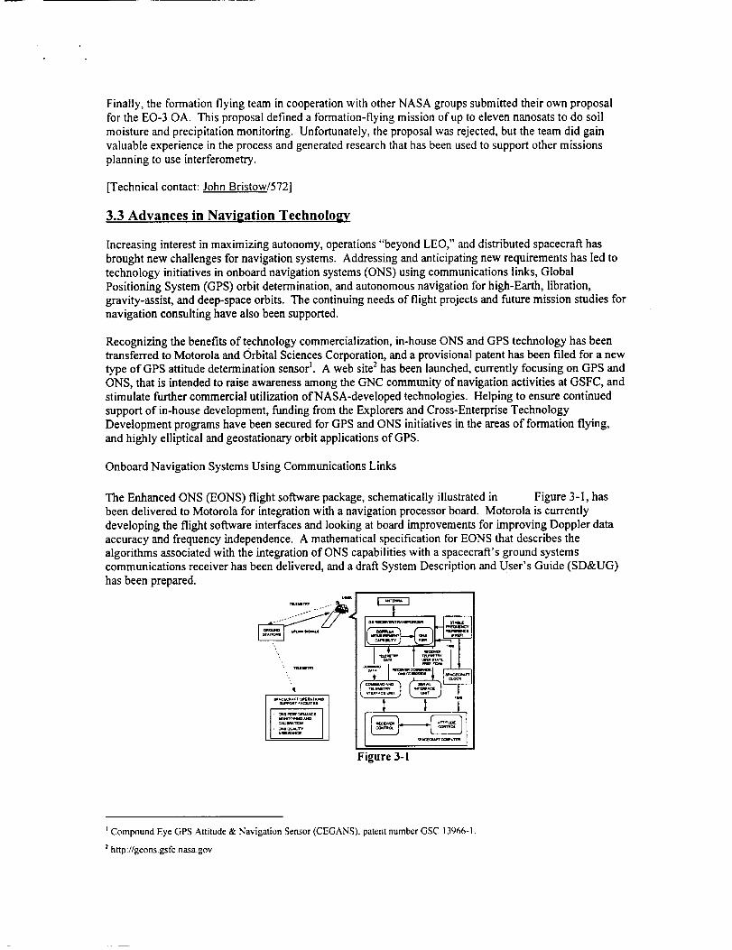
The Enhanced ONS 0EONS) flight software package, schematically illustrated in Figure 3-1, has
been delivered to Motorola for integration with a navigation processor board. Motorola is currently
developing the flight software interfaces and looking at board improvements for improving Doppler dataaccuracy and frequency independence. A mathematical specification for EONS that describes the
algorithms associated with the integration of ONS capabilities with a spacecraft's ground systemscommunications receiver has been delivered, and a draft System Description and User's Guide (SD&UG)
has been prepared.
WACEC_A_ _T_'I
Figure 3-1
t Compound Eye GPS Attitude & Navigation Sensor (CEGANS), patent number GSC 13966-1.
2http://geonsgs fc nasagov
[Technicalcontact:Cheryl Gramlin_/572]
3.4 Global Positionin__ System (GPS) Orbit Determination
Studies supporting formation flying and highly elliptical and geosynchronous orbit missions have been
accomplished• A major new release of the GPS Enhanced Orbit Determination (GEODE) flight softwarehas been delivered. These accomplishments are described below.
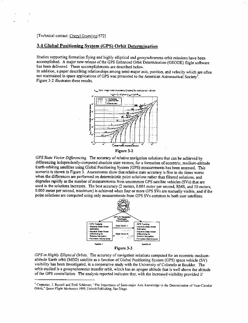
In addition, a paper describing relationships among semi-major axis, position, and velocity which are often
not maintained in space applications of GPS was presented to the American Astronautical Society 3.Figure 3-2 illustrates these results.
%,_ (Semi-major Axis Uncertainty) [meter,J] for o,lb# pedod - 90 rr_
' ' : _ E r r
lo / -- ,.--_.- i ! ! !
tJ I i i Ii'°I.......................| _ _! ' :.
io ' io" Io" Io' lo' Io f 10'%(RadII P0dU_ Uncm_'_ ) Im_=_l
Figure 3-2
GPS State Vector Differencing. The accuracy of relative navigation solutions that can be achieved bydifferencing independently-computed absolute state vectors, for a formation of"eccentric, medium-altitudeEarth-orbiting satellites using Global Positioning System (GPS) measurements has been assessed• This
scenario is shown in Figure 3. Assessments show that relative state accuracy is five to six times worse
when the differences are performed on deterministic point solutions rather than filtered solutions, and
degrades rapidly as the number of measurements from uncommon GPS satellite vehicles (SVs) that areused in the solutions increases. The best accuracy (2 meters, 0.001 meter per second, RMS, and 10 meters,0.005 meter per second, maximum) is achieved when four or more GPS SVs are mutually visible, and if thepoint solutions are computed using only measurements from GPS SVs common to both user satellites•
• Abeo4dce State veer=' State Vector I • Absolute State Veck_
Es_motJon "= Es_matton
Dif_renclng for State Vectoq N D_ffefenc_ng for
Rela_ve Nay(gabon < L Relative Navigation• Focmat_on Miintenince • Formation Maintenance
Satellite I _;lle_le N
Figure 3-3
GPS in Highly Elliptical Orbits. The accuracy of"navigation solutions computed for an eccentric medium-
altitude Earth orbit (MEO) satellite as a function of Global Positioning System (GPS) space vehicle (SV)visibility has been investigated, in a cooperative study with the University of Colorado at Boulder. The
orbit studied is a geosynchronous transfer orbit, which has an apogee altitude that is well above the altitude
of the GPS constellation. The analysis reported indicates that, with the increased visibility provided if
1Carpenter, J. Russell and Emil Schiesser, "The Importance of Semi-major Axis Knowledge in the Determination of Near-CircularOrbits," Space Flight Mechanics 1999, Univelt Publishing,San Diego.
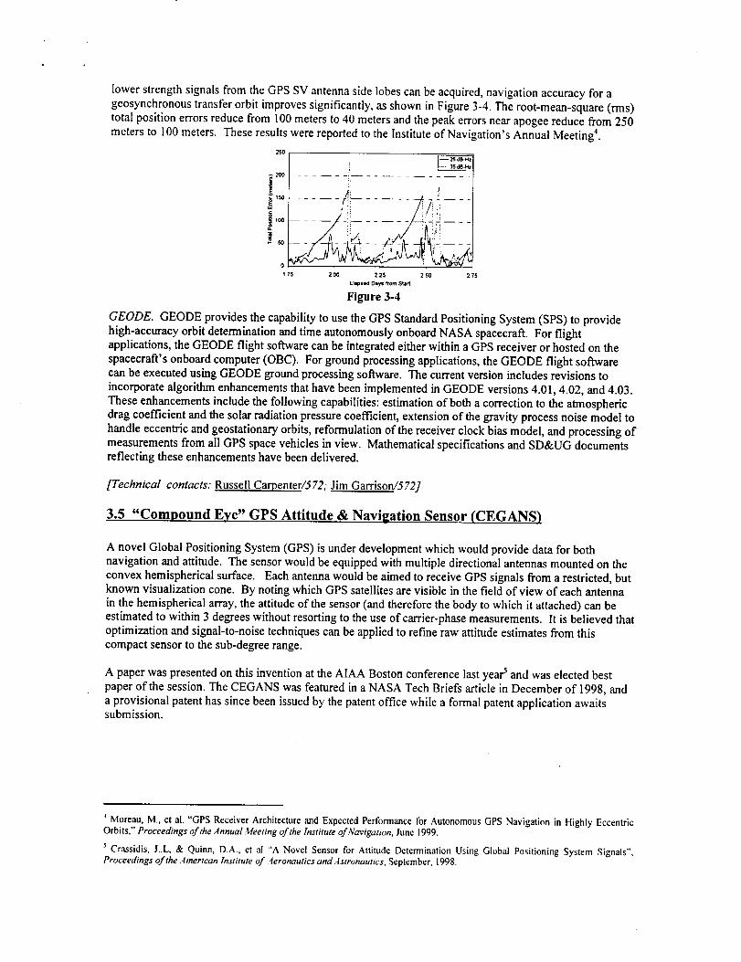
lower strength signals from the GPS SV antenna side lobes can be acquired, navigation accuracy for a
geosynchronous transfer orbit improves significantly, as shown in Figure 3-4. The root-mean-square (rms)total position errors reduce from 100 meters to 40 meters and the peak errors near apogee reduce from 250
meters to I00 meters. These results were reported to the Institute of Navigation's Annual Meeting 4.
200
t_150
100
0
1 75 2 O0 2 25 2 SO 2 75
Elapsed Diy_ from Start
Figure 3-4
GEODE. GEODE provides the capability to use the GPS Standard Positioning System (SPS) to provide
high-accuracy orbit determination and time autonomously onboard NASA spacecraft. For flightapplications, the GEODE flight software can be integrated either within a GPS receiver or hosted on the
spacecraft's onboard computer (OBC). For ground processing applications, the GEODE flight softwarecan be executed using GEODE ground processing software. The current version includes revisions to
incorporate algorithm enhancements that have been implemented in GEODE versions 4.01, 4.02, and 4.03.
These enhancements include the following capabilities: estimation of both a correction to the atmosphericdrag coefficient and the solar radiation pressure coefficient, extension of the gravity process noise model to
handle eccentric and geostationary orbits, reformulation of the receiver clock bias model, and processing ofmeasurements from all GPS space vehicles in view. Mathematical specifications and SD&UG documentsreflecting these enhancements have been delivered.
[Technical contacts: Russell Carpenter/572; Jim Garrisort/572]
3.5 "Compound Eye" GPS Attitude & Navisation Sensor (CEGANS)
A novel Global Positioning System (GPS) is under development which would provide data for bothnavigation and attitude. The sensor would be equipped with multiple directional antennas mounted on the
convex hemispherical surface. Each antenna would be aimed to receive GPS signals from a restricted, butknown visualization cone. By noting which GPS satellites are visible in the field of view of each antenna
in the hemispherical array, the attitude of the sensor (and therefore the body to which it attached) can beestimated to within 3 degrees without resorting to the use of carrier-phase measurements. It is believed that
optimization and signal-to-noise techniques can be applied to refine raw attitude estimates from thiscompact sensor to the sub-degree range.
A paper was presented on this invention at the AIAA Boston conference last yea_ and was elected bestpaper of the session. The CEGANS was featured in a NASA Tech Briefs article in December of 1998, and
a provisional patent has since been issued by the patent office while a formal patent application awaitssubmission.
Moreau, M., et al. "GPS Receiver Architecture and Expected Performance for Autonomous GPS Navigation in Highly Eccentric
Orbits," Proceedings of the Annual Meeting of the Institute of Navigation, June 1999.
Crassidis, J..L, & Quinn, D.A., et al "A Novel Sensor for Attitude Determination Using Global Positioning System Signals",
Proceedings of the Amerlcan Institute of Aeronautics and Astronautics, September, 1998.
[Technical contact." David Quinn/572]
3.6 Autonomous Navigation for High-Earth, Libration, Gravity-assist, and Deep-space Orbits
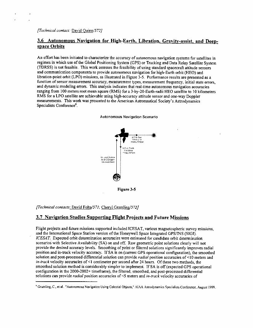
An effort has been initiated to characterize the accuracy of autonomous navigation systems for satellites in
regimes in which use of the Global Positioning System (GPS) or Tracking and Data Relay Satellite System(TDRSS) is not feasible. This work assesses the feasibility of using standard spacecraft attitude sensors
and communication components to provide autonomous navigation for high-Earth orbit (HEO) andlibration-point orbit (LPO) missions, as illustrated in Figure 3-5. Performance results are presented as a
function of sensor measurement accuracy, measurement types, measurement frequency, initial state errors,and dynamic modeling errors. This analysis indicates that real-time autonomous navigation accuraciesranging from I00 meters root mean square (RMS) for a 3-by-20-Earth-radii HEO satellite to 10 kilometers
RMS for a LPO satellite are achievable using high-accuracy attitude sensor and one-way Doppler
measurements. This work was presented to the American Astronautical Society's AstrodynamicsSpecialists Conference 6.
Autonomous Navigation Scenario
,:+E_ctloJ]aJ
_qasu_eme.l
Figure 3-5
[Technical contacts: David Folta/571; Cheryl Gramlin_572]
3.7 Navigation Studies Supporting Flight Projects and Future Missions
Flight projects and future missions supported included ICESAT, various magnetospheric survey missions,
and the International Space Station version of the Honeywell Space Integrated GPS/INS (SIGI).ICESA T. Expected orbit determination accuracies were estimated for candidate orbit determinationscenarios with Selective Availability (SA) on and off. Raw geometric point solutions clearly will not
provide the desired accuracy levels. Smoothing of point or filtered solutions significantly improves radial
position and in-track velocity accuracy. If SA is on (current GPS operational configuration), the smoothedsolution and post-processed differential solution can provide radial position accuracies of < 10 meters andin-track velocity accuracies of < 1 centimeter per second after 24 hours. Of these two methods, the
smoothed solution method is considerably simpler to implement. If SA is off (expected GPS operationalconfiguration in the 2000-2002+ timeframe), the filtered, smoothed, and post-processed differentialsolutions can provide radial position accuracies of <5 meters and in-track velocity accuracies of
Gramhng, C., et al. "Autonomous Navigation Using Celestial Objects," AIAA Astrodynamics Specialists Conference, August 1999.
<l-centimeterpersecondafter24hours.Ofthesethreemethods,thefilteredandsmoothedsolutionmethodsareconsiderablysimplertoimplementthanthepost-processeddifferentialapproach.Magnetospheric Survey Missions. Orbit determination error analysis has been performed to determine thepredicted accuracy for three magnetosphere mapping missions: a mission that would use a constellation of
250 small satellites ("Magneto"), and two phases of a mission that uses a four-satellite formation (MagneticMultiscale mission, MMS).
For the Magneto mission, each satellite would have a perigee height of 1.4 Earth radii. The apogee heightvalues would range from 5- to 25-Earth radii. The inclination varies from 0- to 15-degrees. Tracking dataconsists of one-way return Doppler data from I 1-meter S-band ground stations at Hawaii, Puerto Rico,
Hartebeesthok, Diego Garcia, and the three DSN sites at Canberra, Goldstone, and Madrid; tracking station
angle data could also be utilized. The analysis shows that 14-day tracking arcs with Doppler only data willmeet the mission's 3000 km position requirement.
MMS Phase I will require knowledge of absolute position and inter-spacecraft range to 100 km in its 1.2 by
12 Earth radii, 10 degree inclination orbit. Tracking data consisting of 30 minutes per orbit of Doppler datausing Universal Space Network (USN) X-band ground stations located at Hawaii, Wallops Island, and
Poker Flats, and both coherent and non-coherent Doppler data could be utilized. When using coherentDoppler data, an 8-day tracking span length should be used with at least one pass near perigee each day.
When using non-coherent Doppler data, the frequency bias and drift should be estimated using an 8-daytracking span length with at least one pass near perigee each day. With respect to the inter-range accuracy,
it has been determined that maximum error between two spacecraft was 60 meters when using a minimum
tracking station elevation angle of 15 degrees, and 127 meters when using a minimum tracking stationelevation angle of 7 degrees. It should be mentioned that the latter results correspond to a 97% to 99%
correlation between the non-random errors common to the satellites, which is somewhat higher than the90% to 95% correlation typically expected.
MMS Phase III differs from Phase I in having an 8x80 Earth radii orbit, and 28.5 degree inclination. Both
DSN and USN tracking stations could be utilized. Due to the long period of this orbit (approximately 17days), an 18-day tracking span has been studied. Results show that the DSN-only cases will not meet the
I00 kilometer requirement. The cases with the additional USN tracking will meet the I00 kilometerrequirement. The def'mitive accuracies using the DSN and USN tracking vary from 2- to 31-kilometers. Atleast two perigee passes per data span are recommended.
SIGL The SIGI provides an attitude determination capability that has been developed in-house. Support tothis effort has included ground support equipment and performance analysis software development,consultation for and development of flight software, troubleshooting support to resolve coordinate systemsand interface issues with both the GPS Test Facility's GPS signal simulator and the ISS flight software, and
attitude performance analysis. Support has been provided for SIGI flight software releases 4.11 through4.23. Consultation in the areas of attitude performance evaluation, SIGI software issues, and mission
design has also been provided to the Johnson Space Center in support of a Space shuttle flight test of theSIGI to occur on STS-101.
[Technical contact: Russell Carpenter�572]

4.0 Future Mission Analysis
In FY99, the GNC continued its participation in supporting a wide variety of future mission concepts. Thissection describes the analyses performed which range from science instrument feasibility studies to fullmission concept definitions.
4.1 IMDC Integrated Mission Design Center
The Integrated Mission Design Center (IMDC) is dedicated to innovation in space mission design &
advanced concepts development to increase value for NASA and its customers. In the IMDC, subsystemengineers (e.g. mission design, attitude control, propulsion, mechanical, communications, thermal,
command and data handling, power, and ground systems) gather to conceptualize and perform missiontrade studies in the presence of the customer (i.e. Project Scientist, Principal Investigator, etc.). The end
result is a spacecraft design and an operations concept that the customer can use in proposal developmentfor new mission opportunities (i.e. announcements of opportunity).
The IMDC became operational in Spring, 1997 and as of this writing has supported over 50 mission studies
and focus sessions for both Earth science and space science applications. A typical IMDC study sessionbegins with a mission design brief'rag by the customer. The briefing is followed by design sessions to
perform the system and subsystem level trades agreed upon with the customer. Typical design sessions last
from 1 - 2 weeks. On many occasions, multiple visits to the IMDC are needed as a mission conceptmatures.
GNC analysts support the IMDC using their expertise in trajectory design, orbit analysis, and missionplanning as well as attitude control system (ACS) design, ACS hardware selection and performance
evaluation. A sample of the IMDC missions supported by the GNC in FY99 included:
Coriolis: Coriolis is a Naval Center for Space Technology ('NCST) mission designed to measure
surface level wind direction and speed over the ocean using a microwave polarimeter. The NCSTused the IMDC on two occasions as a simulated Rapid Spacecraft Development Office (RSDO)
vendor to evaluate their requirements specifications document. GNC analysts analyzed the ACSrequirements, orbit selection, maneuver requirements, and assisted in the operations conceptanalysis.
>, NPOESS Preparatory Project (NPP): NPP intends to demonstrate and validate pre-operationalinstruments and algorithms prior to first flight of NPOESS (NOAA Polar Orbiting EnvironmentalSatellite System). NPP visited the IMDC twice in FY99. The first visit was to evaluate the
requirements for creating a baseline design. The f'mal visit was to evaluate the design againstpotential spacecraft found in the RSDO catalog.
EO-3 NEXUS/RedEFe: The IMDC supported three weeks of analysis on the NEXUS/RedEyecollaboration for the EO-3 competition. GNC analysts supported the operations design concept of
moving NEXUS/RedEye from a low-Earth, shuttle orbit to geostationary orbit. Trade studies wereperformed on different propulsion methods (solid/liquid, all-liquid, solid/solid) and in the end, a
dual-solid motor architecture was adopted. ACS work involved analyzing the two differentobserving modes of this proposal - Earth pointing for RedEye and stellar pointing for NEXUS andworking with instrument control engineers and Pl to establish necessary ACS accuracy and jitter
requirements. ACS analysts also devised necessary control modes for the different phases of themission and recommended the necessary components for each mode. Trade studies were
performed on one star tracker versus two, gyro selections to accommodate extreme high rate andlow rate; four reaction wheels versus three; and GPS options for future technology research.
MAXIM: The MAXIM mission involves the formation flying of separate optics and detector
spacecraft to collect X-rays in a heliocentric drift-away orbit. The mission concept relies on anentirely new concept of formation flying. GNC analysts worked to try to validate the MAXIM
concept.Inorderto achieve their X-ray science, the MAXIM P.I. requires a 450 km focal length
between his optics and detectors, it is desired to obtain this focal length by formation flying theoptics and detectors as two independent spacecraft. The challenge is to formation fly the detectors
around the optics at a specific range and maintain this range and attitude to point at celestial
targets for observations on the order of 7 days. When a new target is selected, the optics will slewto the target but the detectors must correct its orbit to move in space relative to the optics andmaintain the 450 km focal length. Work will continue outside of the IMDC to simulate the
formation flying concept. Another challenge of MAXIM mission is the 0.5 milli-arc-seconds
pointing accuracy requirement for the optics spacecraft and the 3-ram lateral pointing accuracyrequirement for the detector spacecraft. ACS analysts worked with PI to derive ACS pointing
accuracy and jitter requirements, performed simulations to assess feasibility to adopt NGST designfor coarse pointing, and analyzed fine pointing using the instrument sensor as an attitude sensor toclose the loop. ACS modes for both the optics and detector spacecraft were derived and sensors
for each mode were selected. Trades were performed on actuator selection (reactions wheels,pulsed plasma thrusters, or both) for rate null/sun acquisition, science, and slew control.
DS-5 Collaboration: GNC analysts supported the IMDC effort to evaluate three potential DS-5
missions as part of NASA's New Millenium Program (NMP). Work included mission concept
brainstorming of the three options - a Solar Sail demonstration, a Force-Free spacecraft pair fordetecting gravity waves, and a Nanosat concept to evaluate miniaturization of instrument andhardware technologies.
MFV- The Maxwell, Faraday, Vlasov (MFV) is a I month mission designed to directly measure
electric currents using the three independent techniques proposed by physicists' whose namescomprise the project name. One of the three techniques involves the release of 12 miniature
freeflying magnetometers (FFM's) prior to entry into high auroral activity at three times duringthe mission. The main spacecraft would receive data from the FFM's over one-half to three orbits.
GNC analysts worked with the PI to examine FFM release velocities and subsequent relative
motion. Minimizing the relative range between the FFM's and the main spacecraft maximized thescience return. Attitude control work involved defining spin axis orientation, spin rates, control
modes and functions of each control mode. ACS analysts specified the locations and alignmentrequirements for magnetometers and magnetic coils. Sizing of spin and precession coils was based
on the FAST mission. Since MFV is a slow spinner, managing the inertia ratio is critical. ACSanalysts worked closely with the structure designer in the arrangement of the hardware. This
mission was made more challenging by the requirement to fly as a secondary payload.
ECCO & CREAM: In addition to Earth orbiting free-flyers, IMDC work has included the supportof two balloon payloads designed to measure cosmic rays. GNC support has primarily been in thearea of identifying ACS components to meet the instrument pointing requirements. Further
analysis was performed to understand the implications of the balloon disturbance environment.Analysts also supported communications link studies.
[Technical contacts: Jennifer Bracken/571;.Michael Mesarch/572; Dave Olney/572; Josephine San/572;Frank Vaughrd572]
4.2 Mission Concept Support
In addition to IMDC support, GNC analysts supported other varied mission concept studies:
Sun-Earth Connections (SEC) Roadmap: GNC mission analysts supported mission design activities for
the SEC Roadmap. In all, twelve mission concepts were examined for methods of collecting the desiredscience data. The twelve missions studied included: conventional, low-Earth orbit, geosynchronous orbit,highly elliptical Earth orbit, non-Keplerian 'pole-sitters' above the Earth, and orbits at or inside Mercury's
orbit (0.39 astronomical units). The science data capture was accomplished with single satellites orconstellations of up to 40 satellites. In supporting the roadmap, it was apparent that many missions would
benefit greatly from advances in solar sail technology and miniaturization of instruments and components.
Global Electro@namics Connections (GEC): The GEC mission involves taking in situ measurements of
the Earth's ionosphere using four identical spacecraft. The four spacecraft will fly in formation (as close as8 km) to examine the variability in the ionosphere. As these spacecraft fly at such low altitudes,
atmospheric drag will continually cause the orbit to decay. Mission analysts continue to examine theamount of propellant necessary to provide for ample science return during a two year mission. Further
analysis on the launch initial conditions and evolution of the perigee latitude and local time history will
help the GEC science team to plan for interesting and varied ionospheric conditions (e.g. combinations ofseason, day vs. night, auroral vs. mid-latitude, etc.). GEC has also visited the IMDC on three separateoccasions for iterations on the spacecraft design. During these visits, ACS engineers have continued to
refine hardware selection. Included in the analysis is the feasibility of designing an Integrated Power and
ACS (IPACS) flywheel system - a new technology development.
Magnetospheric Multi-Scale (AIMS): The MMS mission is designed to investigate the Earth'smagnetosphere in the regions of the magnetopause and plasma sheet. Five spacecraft will fly in a loose
formation that will form a double tetrahedron at orbit apogee. The mission consists of four phases in which
the orbit ranges between 1.2 x 12 Earth radii (at 10° inclination) and 10 x 50 Earth radii (at 90 ° inclination).
Flight dynamics analysis support for the past year has consisted primarily of conferring with the ProjectManager and Project Scientist to formulate mission science requirements and spacecraft operational
requirements and performing analysis to identify and resolve conflicts as related to the orbit design.Analysis to determine the effect of launch epoch and initial clock angle, with respect to the magnetosphere,
on maximum shadow length and dwell time in the plasma sheet during Phases 1 and 2 is nearingcompletion. Analysis tasks for the upcoming year will include the design of the two sets of double lunar
swingbys (Phase 3) required to transition to the Phase 4 orbit and development of an efficient control
strategy to maintain the double tetrahedron at orbit apogee throughout the mission life.
Space Weather Concepts: GNC analysts provided inputs to GSFC scientists for a Space Weather
Workshop in April of 1999. Analysts assisted in assessing feasibility of several different mission concepts.The missions included a solar polar orbiter, simulated solar comet, and a distant retrograde orbit (DRO)
constellation. Interest in a four spacecraft DRO, to monitor solar weather with ten times the response timeof SOHO, has prompted a future paper in The Journal of Atmospheric and Solar-Terrestrial Physics.
[Technical contacts: Greg Marr/572; Michael Mesarch/572; Karen Richon/572; Frank Vaughn/572]
5.0 Attitude Determination
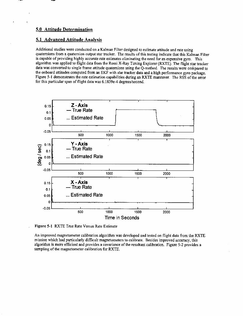
5.1 Advanced Attitude Analysis
Additional studies were conducted on a Kalman Filter designed to estimate attitude and rate using
quaternions from a quatemion output star tracker. The results of this testing indicate that this Kalman Filter
is capable of providing highly accurate rate estimates eliminating the need for an expensive gyro. This
algorithm was applied to flight data from the Rossi X-Ray Timing Explorer (RXTE). The flight star tracker
data was converted to single frame attitude quaternions using the Q-method. The results were compared to
the onboard attitudes computed from an EKF with star tracker data and a high performance gyro package.
Figure 5-1 demonstrates the rate estimation capabilities during an RXTE maneuver. The RSS of the error
for this particular span of flight data was 6.153%-4 degrees/second.
0.15
0.1
0.05
0
-0.05
0.15O
¢n 0.1
¢_ 0.05
"0 0
-0.05
0.15
0.1
0.05
0
-0.05
I
Z - Axis-- True Rate
... Estimated Rate
I
50OI
Y - Axis-- True Rate
... Estimated Rate
I I
1 I
1000 1500 2000
t I I
I I 1 1
500 1000 1500 2000
I
X - Axis-- True Rate
... Estimated Rate
I I I
I I I I
500 1000 1500 2000
Time in Seconds
Figure 5-1 RXTE True Rate Versus Rate Estimate
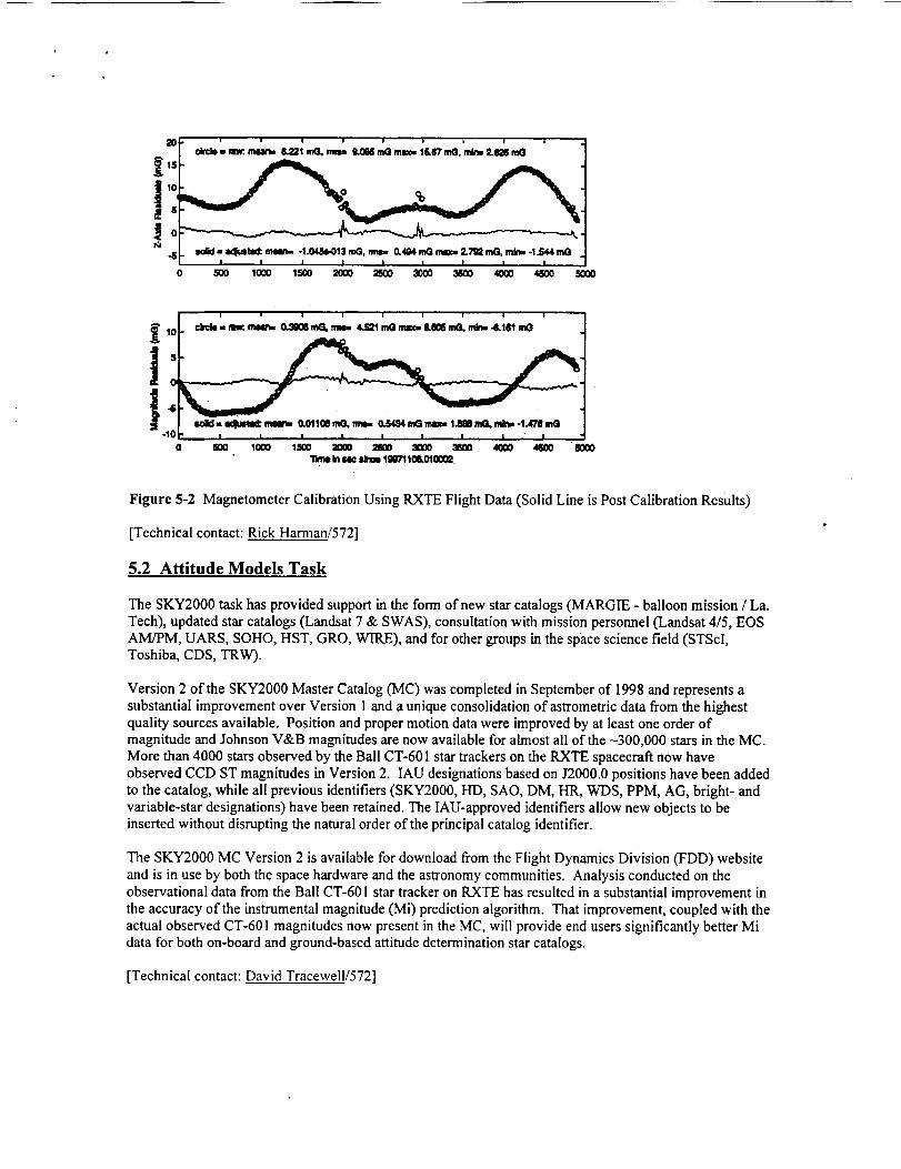
An improved magnetometer calibration algorithm was developed and tested on flight data from the RXTE
mission which had particularly difficult magnetometers to calibrate. Besides improved accuracy, this
algorithm is more efficient and provides a covariance of the resultant calibration. Figure 5-2 provides a
sampling of the magnetometer calibration for RXTE.
0 500 1000 1,500 _QO _ 3000 3500 4000 4500 5000
0 800 tO(X) 1500 _000 2500 _ _ 4_0 4_00 "6000
"tittle In _ _ 1_7'1i_0t0002
Figure 5-2 Magnetometer Calibration Using RXTE Flight Data (Solid Line is Post Calibration Results)
[Technical contact: Rick Harman/572]
5.2 Attitude Models Task
The SKY2000 task has provided support in the form of new star catalogs (MARGIE - balloon mission / La.Tech), updated star catalogs (Landsat 7 & SWAS), consultation with mission personnel (Landsat 4/5, EOS
AM/PM, UARS, SOHO, HST, GRO, WIRE), and for other groups in the space science field (STScl,Toshiba, CDS, TRW).
Version 2 of the SKY2000 Master Catalog (MC) was completed in September of 1998 and represents a
substantial improvement over Version 1 and a unique consolidation of astrometric data from the highestquality sources available. Position and proper motion data were improved by at least one order ofmagnitude and Johnson V&B magnitudes are now available for almost all of the -300,000 stars in the MC.More than 4000 stars observed by the Ball CT-601 star trackers on the RXTE spacecraft now have
observed CCD ST magnitudes in Version 2. IAU designations based on J2000.0 positions have been added
to the catalog, while all previous identifiers (SKY2000, HD, SAO, DM, HR, WDS, PPM, AG, bright- andvariable-star designations) have been retained. The IAU-approved identifiers allow new objects to beinserted without disrupting the natural order of the principal catalog identifier.
The SKY2000 MC Version 2 is available for download from the Flight Dynamics Division (FDD) website
and is in use by both the space hardware and the astronomy communities. Analysis conducted on theobservational data from the Ball CT-60 ! star tracker on RXTE has resulted in a substantial improvement in
the accuracy of the instrumental magnitude (Mi) prediction algorithm. That improvement, coupled with theactual observed CT-601 magnitudes now present in the MC, will provide end users significantly better Midata for both on-board and ground-based attitude determination star catalogs.
[Technical contact: David Tracewell/572]

5.3 Magnetometer Navigation
GNCC personnel, jointly with Dr. Itzhack Bar-itzhack of the Technion Israel Institute of Technology, havedeveloped and tested a low cost system for simultaneous and autonomous attitude, orbit, and rateestimation of a low earth orbit satellite. The system relies mainly on magnetometer data, a reliable and low
cost sensor. The estimation is performed using an Extended Kalman filter (EKF) algorithm. The filter state
can be chosen to estimate all three components, namely attitude, orbit, and rate or a subset. This algorithmwas successfully implemented for the Transition Region and Coronal Explorer (TRACE) mission. The
TRACE sensor complement consisted of a magnetometer and a course digital sun sensor. The results ofestimating all 13 states can be seen in Figures 5-3/-4/-5. During FY99, analysis of the attitude and orbit
estimation subset was conducted to determine the feasibility of further improving the measurement datathrough the incorporation of more sophisticated sensor noise models. Dr. Wallace Larrimore of Adaptics,
Inc. developed a statistical model of the RXTE magnetometer data. This model was incorporated into theRXTE EKF, resulting in improved attitude and orbit estimates. The results were presented at the 21st
Annual AAS Guidance and Control Conference in a paper titled "Improved Modeling in a Matlab-Based
Navigation System'
Negotiations with the CRV X-38 project at JSC began in FY99. The X-38 project is interested in
determining if the magnetometer can provide a backup attitude solution to the prime attitude system basedon GPS data. Attitude analysis using the magnetometer-based EKF will be conducted in Code 572.
Numerous studies with the EKF will be conducted to determine the convergence potential from anunknown initial attitude within the time constraints of the necessary CRV orbit maneuvers. A preliminary
result is given in Figure 5-6. With simulated data, the EKF overcame an initial attitude error of I 15
degrees and converged to within 5 degrees in 5 minutes, meeting the CRV constraints. Concurrently withthe analysis, Code 573 will build the flight and test magnetometers for JSC based on the SMEX-lite
magnetometer design. Following the test flight of the X-38 vehicle, the recorded magnetometer flight datawill be analyzed in Code 570 and the magnetometer-based attitude estimates will be provided to JSC forfurther evaluation.

Figure5-3RSSofTRACEOrbitalPositionError
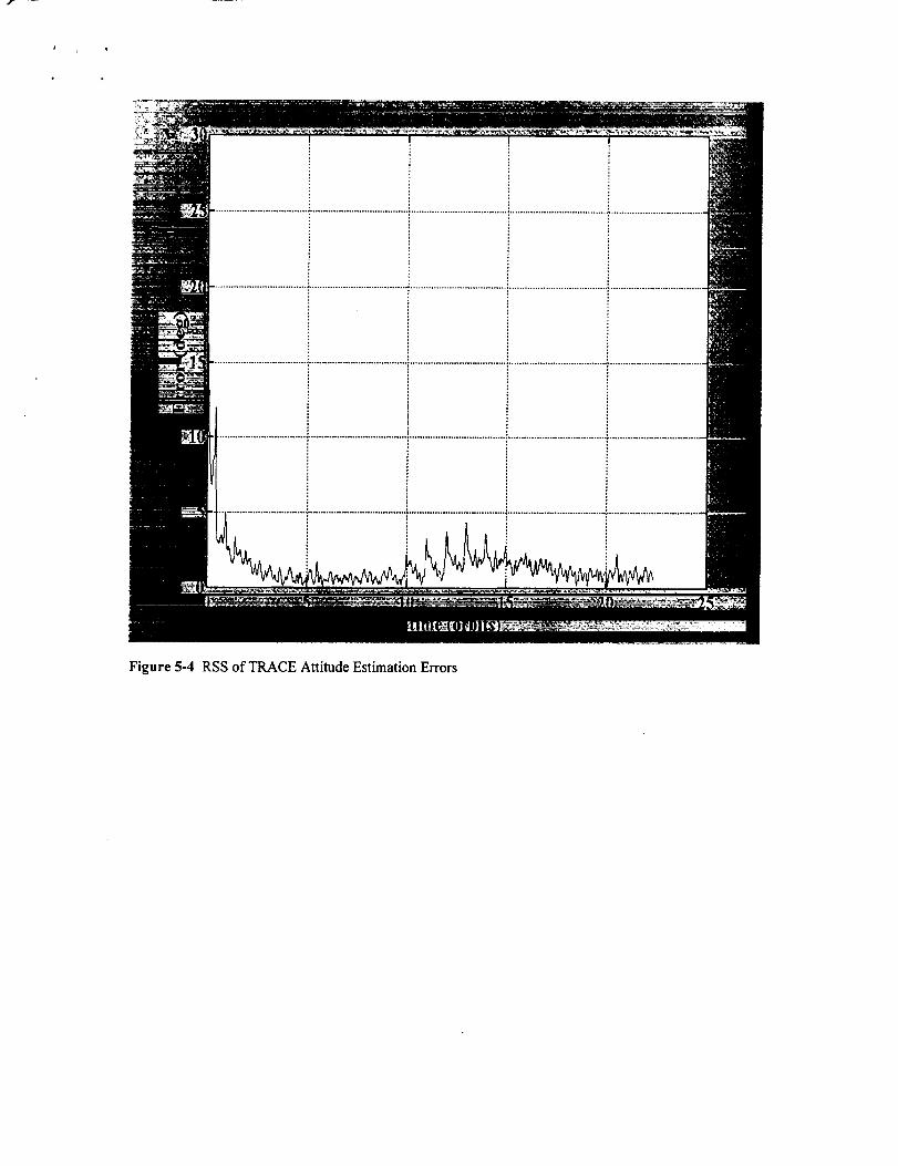
Figure5-4 RSS of TRACE Attitude Estimation Errors

Figure5-5RSSofTRACERateEstimationErrors

!
!
!
I
!
!
I
Figure 5-6 Preliminary CRV Magnetometer Attitude Test Result -Initial Error was 115 degrees
[Technical contact: Julie Deutschmann/572]
5.4 WIRE Flight Dlmamics Attitude Support
The Flight Dynamics Analysis Branch successfully supported the Wide-Field Infrared Explorer (WIRE)
launched on March 5, 1999. Shortly after launch, the spacecraft started spinning out of control due to thescience instrument cover being blown early. The pyrotechnics controlling the hatch opening malfunctioned
and the heat from the sun in conjunction with onboard cryogen conspired to create an unanticipatedthruster which was beyond the capabilities of the attitude actuators to control. FDAB personnel provided
attitude determination and rate estimation support as we_l as providing varioous unplanned planningproducts until the spacecraft was successfully transitioned to pseudo-normal operations though with aseverely damaged science instrument. Once in normal operations, FDAB personnel performed a
calibration of the gyros. An example of the pre-calibration results can be seen in Figure 5-7, and theresulting post-calibration results can be seen in Figure 5-8.
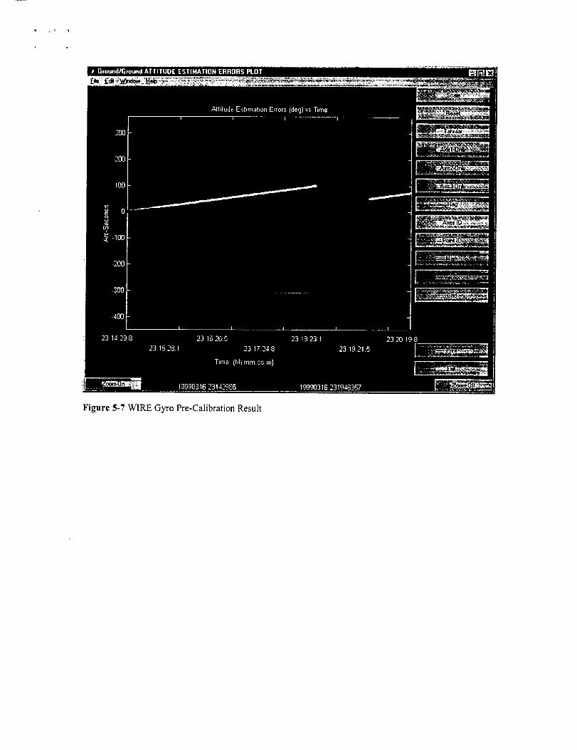
Figure 5-7 WIRE Gyro Pre-Calibration Result
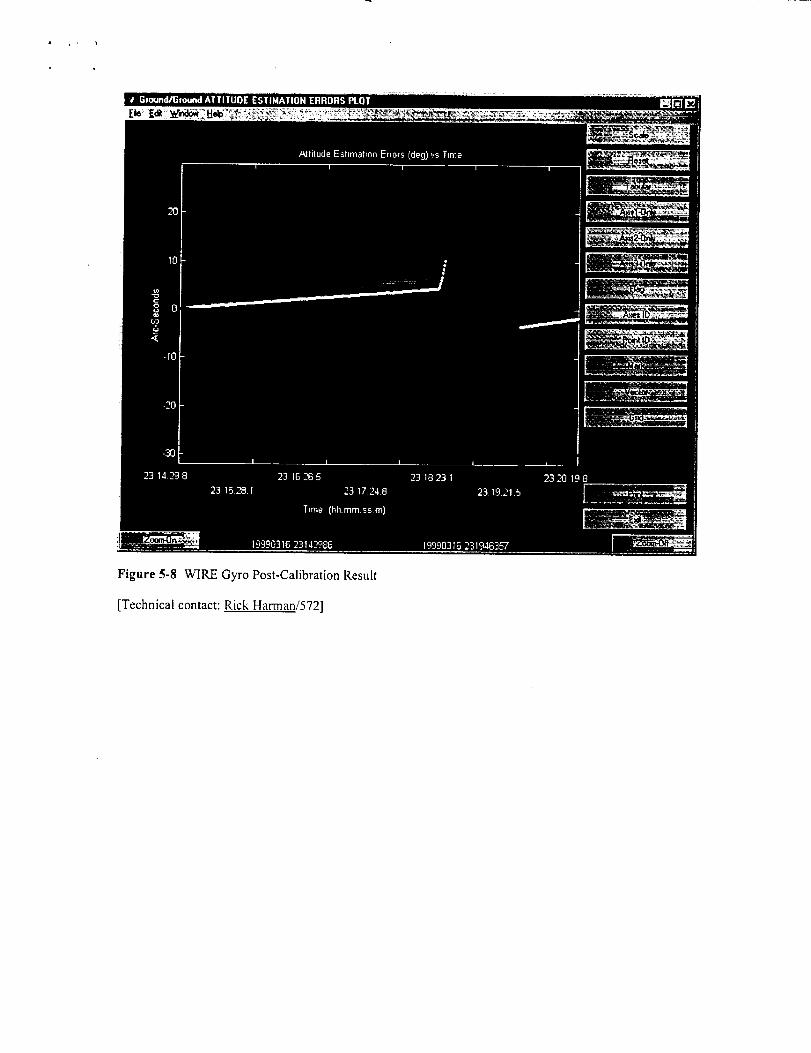
Figure 5-8 WIRE Gyro Post-Calibration Result
[Technical contact: Rick Harman/572]

t, _ • •
6.0 GNCC Flight Dynamics.Data Lab
GNCC began configuration of the Flight Dynamics Lab located in Building I 1. This lab
will be used for the development, test, integration, and operation of software systems to
perform flight dynamics functions and analysis in support of space missions. When fully
configured the lab will have the capability to receive spacecraft telemetry and navigation
data, and have voice and video communication links for the performance of thesefunctions.
Items completed were the room construction, installation of voice and video equipment,
and installation of several computers. This initial configuration allowed support for the
Lunar Prospector end of mission to be done from the lab.
Plans for the coming year call the installation of computers, installation of an on line data
storage device, and installation of servers. When this is complete the lab will be able to
support all planned functions as well as providing an area for GNCC software analysisinstruction.
[Technical contact: Sue Hoge/572]
7.0 lnteragency Activities
7.1 CCSDS - Consultative Committee for Space Data Systems
Felipe Flores-Amaya (Code 572) represents GNCC as the chairman for the P1J Sub-Panel under theConsultative Committee for Space Data Systems (CCSDS).
The Consultative Committee for Space Data Systems (CCSDS) is an international organization of space
agencies interested in mutually developing standard data handling techniques to support space researchconducted exclusively for peaceful purposes. Ref. http://www.ccsds.org/
Sub-Panel P 1J is specifically chartered to investigate and recommend Navigation Data standards. P IJ
currently has 16 members, representing the following international agencies: Chinese Academy of SpaceTechnology (CAST), China; Communications Research Centre (CRC),Canada; (CNES), France; DeutscheZentrum fur Lufi- und Raumfahrt (DLR), Germany; European Space Agency (ESA), Europe; National
Aeronautics and Space Administration (NASA), USA; and National Space Development Agency(NASDA), Japan.
The work of PlJ is accomplished primarily at workshops, conducted at least twice a year, at facilitiescoordinated by the hosting member agency. The main task of P IJ is to generate documents defining the
preferred standards for the exchange of navigation data. A draft of the latest document was reviewedduring the most recent workshop, May 1999, at Newport Beach, California.
Future work will involve investigating- Proximity and in-situ navigation- Interface with GPS, GLONASS, and similar systems
- Autonomous navigation- Tracking stations on other planets- GPS like constellations around other planets
[Technical contact: Felipe Flores-AmavaJ572]
7.2 Flight Mechanics Symposium
The Flight Dynamics Analysis Branch conducted the Flight Mechanics Symposium,May 18-20, 1999. The purpose of this symposium is to provide a forum for specialists in all disciplines ofthe Guidance, Navigation, and Control Center to present, discuss, and exchange information pertaining totheir work in support of GSFC and NASA spacecraft missions. These missions are dedicated to Earthobservations and planetary exploration.
The range of GNCC disciplines involve systems engineering, hardware and components, propulsion,technology development, attitude determination, orbit determination, attitude control system analysis anddesign, sensor calibration, mission analysis, mission design, orbit control, and error analysis. A total ofTBD papers were presented at the 1999 symposium. The papers presented at this symposium are availablein a formal NASA publication.
[Technical contact: John P. Lynch/572]
8.0 ISO9000
The Flight Dynamics Analysis Branch complied with all requirements to ensure readiness for GSFCISO9000 certification.
For details about GSFC ISO activities, please refer to http://arioch.gsfc.nasa.gov/iso9000/index.htm
[Technical contact: Felipe Flores-Amaya/572]
Appendix A - Conferences and Papers
"TRMM On-Orbit Attitude Control System Performance", Brent Robertson, Sam Placanica and WendyMorgenstern, 22nd Annual AAS Guidance and Control Conference, February 1999.
"On-Orbit Performance of the TRMM Mission Mode", Brent Robertson, Sam Placanica, Wendy
Morgenstern, Joseph Hashmall (CSC), Jonathan Glickman (CSC) and Gregory Natanson (CSC), 14thInternational Symposium on Space Flight Dynamics, February 1999.
"Janus Trajectory Design", Greg Mart, presented at the Flight Mechanics Symposium at GSFC, sponsoredby Code 572, May 1999.
"The Importance of Semi-major Axis Knowledge in the Determination of Near-Circular Orbits,"Carpenter, J.. Russell and Emil Schiesser, Space Flight Mechanics 1999, Univelt Publishing, San Diego.
Lauri Newman attended the AAS/AIAA Astrodynamics Specialist Conference in Girdwood, Alaska, onAugust 15-19, 1999.
Bristow, J.O., G.T Dell, K.B Chapman, and D.L. Rosenberg, "Autonomous Formation Flying fxom theGround to Flight ," 1999 Flight Mechanics Symposium, GSFC, Greenbelt, MD.
Bristow, J.O., Weidow, D. "NASA/DoD University Nano-Satellites for Distributed Spacecratt Control,"13 thAnnual Conference on Small Satellites, Logan, Utah
Carpenter, J.R., "Feasibility of Decentralized LQG Control of Autonomous Satellite Formations," 1999Flight Mechanics Symposium, GSFC, Greenbelt, MD.
Carpenter, J.R., D.C. Folta, and D.A. Quinn, "Integration of Decentralized LQG Control into GSFC'sUniversal 3-D Formation Flying Algorithm," 1999 AIAA GN&C Conference, Portland, OR.
Folta, D.C., and D.A. Quinn, "A Universal 3-D Method for Controlling the Relative Motion of MultipleSpacecraft in Any Orbit," AIAA/AAS Astrodynamics Specialist Conference, Boston, MA
Appendix B - Acronyms and Abbreviations
The appendix gives the definitions of acronyms used in this document.
ACE
ACSAFRL
AIARC
CASTCCD
CCSDS
CNESCOTS
CPUCPTCRC
DLRDLS
DSNDST
EIKFEKF
EO-1
EOSERBS
ESAESTOFAST
FDABFDCL
FDSSFMFOT
FOV
FYGADFLYGEAS
GEMGEODE
Attitude Control Electronics
Attitude Control SystemAir Force Research Laboratory
Artificial IntelligenceAmes Research Center
Chinese Academy of Space TechnologyCharged Coupled Device
Consultative Committee for Space Data SystemsCentre Nnational D'etudes Spatiales
Commercial Off-the-Shelf
Central Processing Unit
Comprehensive Performance TestCommunications Research CentreDeutsche Zentntm fur Lug- und Raumfahrt
Double Lunar Swingby
Deep Space NetworkDynamical Systems TheoryExtended Interlaced Kalman Filter
Extended Kalman FilterEarth Orbiter- 1
Earth Observing System
Earth Radiation Budget SatelliteEuropean Space Agency
Earth Science Technology OfficeFast Auroral Snapshot Explorer
Flight Dynamics Analysis BranchFlight Dynamics & Control LaboratoryFlight Dynamics Support System
Flight MechanicsFlight Operations TeamField of View
Fiscal Year
GPS Attitude Determination FlyerGPS Error Analysis System
Goddard Electronics Module
GPS Enhanced Orbit Determination ExperimentGLONASS
GNGNCCGOES
GOTS
GPSGROGSFC
HGA/CPUHTMLIKF
IMAGEIMDC
ISSJHU/APLLP
Global Orbiting Navigation Satellite SystemGround Network
Guidance, Navigation, and Control CenterGeostationary Operational Environmental SatelliteGovernment-off-the-shelf
Global Positioning Satellite
Gamma Ray ObservatoryGoddard Space Flight Center
High-Gain Antenna/Contact Prediction UtilityHyperText Markup Language
Interlaced Kalman Filter
lmager for Magnetopause-to-Aurora Global ExplorationIntegrated Mission Design Center
International Space StationJohns Hopkins University/Applied Physics Laboratory
Lunar Prospector

MAPMITMMSMOCMTASSNASANASDANGSTNGXONMPNOAAOBCPCPIPOESQUESTRMSRTADSRXTESASABERSAGESAILSAMPEXSAOSBIRSMEXSOHOSOMOSPSSTKSWASTDRSTDRSSTRACE
TRMMURL
VO
WWW
Microwave Anistropy ProbeMassachusetts Institute of Technology
Magnetic Multi-scale Mission
Mission Operations CenterMultimission Three-Axis-Stabilized Attitude Support System
National Aeronautical and Space AdministrationNational Space Development Agency of Japan
Next Generation Space TelescopeNext Generation X-Ray Observatory
New Millennium ProgramNational Oceanic and Atmospherics Administration
Onboard Computer
Personal ComputerPrincipal Investigator
Polar Orbiting Environmental Satellites
Quaternion Estimation
Root-Mean-SquareReal-Time Attitude Determination System
Rossi X-Ray Timing Explorer
Selective AvailabilitySounding of the Atmosphere using Broadband Emission Radiometry
Stratospheric Aerosol and Gas ExperimentSatellite Artificial Intelligence Laboratory
Solar, Anomalous, and Magnetospheric Particle ExplorerSolar Astronomical ObservatorySmall Business Innovation Research
Small ExplorerSolar and Heliospheric Observatory
Space Operations Management OfficeStandard Positioning ServiceSatellite Tool Kit
Submillimeter Wave Astronomy Satellite
Tracking Data Relay SatelliteTracking Data Relay Satellite System
Transition Region and Coronal ExplorerTropical Rainfall Measuring Mission
Uniform Resource Locator
Visualization OptionWide-Field Infrared ExplorerWorld Wide Web