Embed Size (px)
Citation preview

NLR-TP-99379
Flight simulator evaluation of the safetybenefits of terrain awareness and warningsystems
R.J. de Muynck and R. Khatwa
brought to you by COREView metadata, citation and similar papers at core.ac.uk
provided by NLR Reports Repository

DOCUMENT CONTROL SHEET
ORIGINATOR’S REF.
NLR-TP-99379
SECURITY CLASS.Unclassified
ORGINATORNational Aerospace Laboratory NLR, Amsterdam, The Netherlands
TITLEFlight simulator evaluation of the safety benefits of terrain awareness and warning systems
PRESENTED AT:The AIAA Guidance, Navigation and Control Conference, Portland (OR), U.S.A. , 9-11 August 1999.
PERMISSIONThe the Netherlands Department of Civil Aviation (RLD) has granted NLR permission to publish thisreport.
AUTHORSR.J. de Muynck and R. Khatwa*
* Rockwell Collins
DATESeptember 1999
pp13
ref8
DESCRIPTORSFlight simulatorsCollision warning devicesWarning systemsTerrainAircraft safetyFlight simulation
ABSTRACTThis paper focuses on an investigation into the operational safety aspects of advanced Terrain Awarenessand Warning Systems (TAWS), conducted under contract to the Netherlands Directorate General of CivilAviation (RLD). The TAWS depicts graphical terrain information on a Navigation Display (ND) andprovides predictive terrain collision alerting. Initially, several ND terrain format displays were evaluated inan exploratory workstation study. The most preferred display format was adopted for follow-up evaluationsin a piloted simulation programme. The objective of phase two was to evaluate the independent effects ofterrain awareness information and predictive terrain alerting. The NLR Research Flight Simulatoremploying the Fokker 100 model served as the test facility. Ten evaluation crews flew fourteen scenarioseach, primarily in terrain-rich environments.

NLR-TP-99379
This investigation has been carried out under a contract awarded by the NetherlandsDepartment of Civil Aviation (RLD), contract number OV/RLD 761/1.RLD has granted NLR permission to publish this report.
This report is based on a presentation held at the AIAA Guidance, Navigation andControl Conference, Portland (OR), U.S.A., 9 - 11 August 1999.
The contents of this report may be cited on condition that full credit is given toNLR and the authors.
Division: FlightIssued: September 1999Classification of title: unclassified
Flight simulator evaluation of the safetybenefits of terrain awareness and warningsystems
R.J. de Muynck and R. Khatwa*
* Rockwell Collins Inc.

������������������������������������ ��� �� ������������������������ �� ������������������������ �� ������������������������ �� ���������������������
�������� ��� �� ���������� ���
�����������
������������� ������������������������������������� ������������������������������������� ������������������������������������� ������������������������
�������������� ������� ������������ ������������������ ������� ������������ ������������������ ������� ������������ ������������������ ������� ������������ ����
������������������������
���� �� ���� � �� �� �� �
� ������ ���
This investigation has been carried out under a contract awarded by the Netherlands Department ofCivil Aviation (RLD), contract number OV/RLD 761/1. The Netherlands Department of CivilAviation (RLD) has granted NLR permission to publish this report.
This report is based on a presentation held at the AIAA Guidance, Navigation and ControlConference, Portland (OR), U.S.A., 9-11 August 1999.
The contents of this report may be cited on condition that full credit is given to NLR and theauthors.
Division: FlightIssued: September 1999Classification of title: unclassified
-2-NLR-TP-99379
Contents
Introduction 3
Workstation Pilot Study 4
Objectives of the Simulator Evaluation 4
Simulation Facility 5
Terrain Awareness and Warning System Description 5
Experimental Design 6
Operational Procedures 7
Test Subjects 8
Evaluation Procedure 8
Data Collection 8
Results and Discussion 8
Conclusions 12
Recommendations 13
References 13
15 Figures
(13 pages in total)

-3-NLR-TP-99379
FLIGHT SIMULATOR EVALUATION OF THE SAFETY BENEFITS OF TERRAINAWARENESS AND WARNING SYSTEMS
R.J. de Muynck* and R.Khatwa†
*National Aerospace Laboratory NLRAnthony Fokkerweg 2
1059 CM, Amsterdam, the NetherlandsTel. +31 20 5113730, Fax +31 20 5113210
e-mail: [email protected]
†National Aerospace Laboratory NLRCurrently employed by Rockwell Collins Inc.
Cedar Rapids, IA52498-3161, USATel. +1 319 295 9028, Fax +1 319 295 8100
e-mail: [email protected]
AbstractThis paper focuses on an investigation into theoperational safety aspects of advanced TerrainAwareness and Warning Systems (TAWS),conducted under contract to the NetherlandsDirectorate General of Civil Aviation (RLD). TheTAWS depicts graphical terrain information on aNavigation Display (ND) and provides predictiveterrain collision alerting. Initially, several ND terrainformat displays were evaluated in an exploratoryworkstation study. The most preferred display formatwas adopted for follow-up evaluations in a pilotedsimulation programme. The objective of phase twowas to evaluate the independent effects of terrainawareness information and predictive terrain alerting.The NLR Research Flight Simulator employing theFokker 100 model served as the test facility. Tenevaluation crews flew fourteen scenarios each,primarily in terrain-rich environments.
The subjects generally had little difficulty inbecoming accustomed to the displayed terraininformation and comments indicated a markedimprovement in terrain situational awareness.Analysis shows a significant improvement in terrainsituational awareness and speed of detectingpotential terrain critical situations. The terraindisplay provided sufficient spatial awareness to theextent that the conditions generating a predictivealert developed relatively few times. The crews didnot perceive a marked improvement in terrainsituational awareness from the predictive terrainproximity alerting. However, the additional safetymargin provided by this alerting algorithm was stillregarded a valuable asset. Relatively few crewsnoticed anomalies on the terrain display associatedwith TAWS database errors.
AbbreviationsATC Air Traffic ControlCFIT Controlled Flight Into TerrainDH Decision HeightDME Distance Measuring EquipmentEGPWS Enhanced Ground Proximity Warning
SystemFMS Flight Management SystemFSF Flight Safety FoundationGCAS Ground Collision Avoidance SystemGPWS Ground Proximity Warning SystemICAO International Civil Aviation OrganisationMDA Minimum Descent AltitudeND Navigation DisplayPFD Primary Flight DisplayQNH Altimeter sub-scale setting to obtain
elevation relative to mean sea levelRLD Rijksluchtvaartdienst; Directorate General
of Civil Aviation of the NetherlandsRFS Research Flight SimulatorSOP Standard Operating ProceduresTAWS Terrain Awareness and Warning SystemTCAS Traffic Alert and Collision Avoidance
System
IntroductionIt is generally accepted that Controlled Flight IntoTerrain (CFIT) is one of the leading categories ofcivil aircraft accidents. Recent safety studies includethose conducted by the Flight Safety Foundation(FSF)/ICAO CFIT and Approach & LandingAccident Reduction Task Forces1,2,3. These TaskForces recommended the application of advancedtechnology to improve situational awareness in thecockpit. Currently, several avionics manufacturersare developing and some are already marketing suchtechnology, most notably in the form of depictinggraphical terrain information on the already installedEFIS displays. Current regulatory activity from the

-4-NLR-TP-99379
FAA and ICAO is focused on rule making formandating the installation of TAWS. In March 1999,ICAO adopted amendments to Annex 6, Parts I andII, which introduce requirements for a predictiveterrain hazard warning function in the GPWS (i.e.EGPWS, GCAS or TAWS). The Society ofAutomotive Engineers (SAE) has published humanfactors guidelines4 for the development of thesesystems.The introduction of such terrain awareness displaysas well as predictive terrain warning systems willimpact flight crew operational procedures. Thesesystems are likely to influence the crew’s spatialawareness as well as their reaction to groundproximity alerts occurring in combination with suchdisplays. For shared displays, in which terrain is oneof several types of information that can be depicted,information prioritisation, discrimination of terraininformation, consistency of coding and symbologyand potential clutter are just some of the issues thatneed to be addressed.
The investigation, on behalf of the RLD, was carriedout into the operational safety aspects of TAWS. Theobjective was to evaluate the independent effects ofterrain awareness information and predictive terrainalerting. More complete details of the study are givenin Ref.5. The current study adds to other recentresearch conducted on the subject of terraindepiction in the flight deck6,7.
Workstation Pilot StudyThe objective of the initial phase of the study was toselect a representative TAWS type system that couldbe pursued further in a full mission researchsimulator. Therefore, prior to the piloted flightsimulator evaluation, a workstation experiment wasconducted to assess candidate Navigation Displayformats depicting terrain. Eight technical airlinepilots from local carriers served as test subjects.Evaluation variables included:• Colour coding schemes to depict terrain altitude
relative to aircraft, e.g. grey, green or brown tints,or combinations, as well as current weather radarcolours (red, yellow and green);
• Altitude spacing between terrain contours - 500or 1000ft intervals;
• The relative altitude below the aircraft at whichnot to depict terrain.
Although the displays presented were “static”, pilotswere able to vary aircraft altitude and position tomimic a dynamic terrain display. In summary, thesubjective workstation evaluation generated thefollowing recommendations:
• The preferred format for the terrain colour codingwas based on brown tints, comparable to that forpaper navigation charts, e.g. Jeppesen;
• Darker colours to indicate higher terrainelevations, as opposed to dark colours for lowterrain, were preferred – just as for paper chartsthat depict terrain contours;
• 1000ft altitude intervals between terrain contourswas the preferred format when compared to theuse of 500ft intervals;
• The use of grey colour coding for displayingterrain below the aircraft was not received well.The preferred approach was to maintain a similarcolour scheme as used for terrain depiction abovethe aircraft – since both were considered hazardsto ultimately avoid.
These results were used to code the format used inthe flight simulator evaluation described below.
Objectives of the Simulator EvaluationThe objective of phase two was to evaluate theindependent effects of terrain awareness informationand predictive terrain alerting. In particular theinfluence on spatial awareness and crew decisionmaking were central to this study.
The basic hypotheses formulated for the experimentdesign were as follows:- Crew acceptability of the TAWS function is
high;- The introduction of predictive terrain alerting
leads to fewer terrain critical situations thansystems with reactive alerting;
- A graphical terrain display leads to earlier crewrecognition of potential terrain conflicts andfacilitates improved crew decision-making.
The investigation also included the observation ofcrew behaviour following terrain alerts and whenerroneous terrain was displayed due to databaseanomalies.
The 2x2 matrix below represents the evaluationindependent variables (awareness and alerting type).Note that ‘alerting type’ refers specifically to thoseaural and visual alerts associated with potentialimpact with terrain (and not the relative terrainaltitude coding for the display).
Table 1: Interface definition matrixStandard
Nav. DisplayNav. Display
& Terrain Data
Reactive alertingInterface A
(GPWS)Interface B
Predictivealerting
Interface CInterface D
(TAWS)

-5-NLR-TP-99379
Interface A represents the GPWS (reactive alertingbased on current conditions, e.g. Radio altimeter,barometric descent rate, etc). This is also thereference treatment condition. Interface B is a GPWSsupplemented by a terrain awareness display (andtherefore does not provide predictive alerting).Interface D equates to TAWS with complete systemfunctionality. Interface C represents a TAWS typesystem minus the terrain awareness display(predictive alerting only). For each of the interfacesin Table 1, GPWS Mk 5 functionality was alwaysprovided as standard - the terrain display andpredictive alerts supplement the basic GPWS.
Simulation FacilityThe piloted evaluation program was executed usingthe NLR’s Research Flight Simulator (RFS). TheRFS features a modern civil transport aircraft glasscockpit, with a moving base motion platform andboth terrain model board and computer generatedvisual system. An Air Traffic Control (ATC)controller station is fully coupled to the RFS. Thevarious aircraft simulation models, avionics sub-systems and cockpit displays that are available can betailored for a specific type of investigation. For thepurpose of this evaluation, the RFS was programmedto simulate a Fokker 100 aircraft. Figure 1 presentsthe RFS cockpit set-up.
Figure 1: Research Flight Simulator Cockpit Layout
Although the cockpit layout does not resemble that ofthe actual aircraft, system functionality was emulatedto the maximum extent possible. The standardFokker 100 Primary Flight Display (PFD) andNavigation Display (ND) formats, and EngineIndication and Crew Alerting System (EICAS) wereused. The Flight Management System, two ControlDisplay Units, integrated Autopilot/Flight Directorand Autothrottle were also used for the evaluation.The Flight Control Panel is glareshield mounted asshown above.
Terrain Awareness and Warning System DescriptionThe experimental TAWS comprised the followingvisual and aural information:- Graphical depiction of relative terrain elevation
on the ND employing brown contours;- Yellow and red alerting areas on the NDs to
provide a visual indication of the predictedcollision area associated with terrain cautions andwarnings respectively. The caution and warningalerts are based on a 60 and 30 second look-aheadrespectively, using current aircraft altitude,position, airspeed, descent rate, turn rate, and anon-board terrain database;
- Aural alerts (“Caution Terrain” and “TerrainAhead - Pull-up”) combined with the above visualalerts;
- Terrain proximity warnings and cautionsannunciated through the master/caution lamp onthe glareshield panel;
- Depiction of a lateral trend vector (predictedflight path over next 30 seconds) on the ND inyellow.
In order to pursue the objectives of the currentinvestigation, terrain was displayed full-time (asopposed to pilot selectable). The display range waspilot selectable. As an example, Figure 2 shows theND during approach into Mexico City.
Figure 2: Navigation Display with Relative TerrainElevation Information
The coding of relative terrain depiction above isdefined using the sideview in Figure 3.

-6-NLR-TP-99379
+1000ft
-1000ft
-100ft
>1000ft above
> 1000ft below
Figure 3: Colour Coding for Relative TerrainDepiction on ND
Experimental DesignA great challenge in the experimental design was theexpected anticipation by test subjects that terraincollisions and/or dangerous proximity to terrainwould occur during the experiment - as the pilotswould be aware of the nature of the evaluation.Similarly, it was anticipated that subject pilots wereunlikely to frequently encounter situations involvingterrain alerts during the experiment since they wouldadhere to given clearances and also strictly followprescribed Standard Operating Procedures.Reproduction of the complex accident causal chainsin an experimental set-up is difficult to achieve. Inaddition, it was anticipated that there would be asignificant learning effect for a particular crew incases where they were exposed to abnormalsituations and emergencies more than once. Exposingsubjects to these latter conditions with more than onecandidate interface was therefore avoided.
For the reasons stated above, a mixed experimentaldesign was adopted. Two subject groups, each of fivecrews (Captain and First Officer), were each exposedto only two interfaces in Table 1. Each subject groupevaluates the two interfaces in a repeated measuresfashion, and the two subject groups themselves areinvolved in a randomised subject design. Theevaluation of the individual effects of both terraindisplay information and that of predictive terrainproximity alerting could be investigated in this way.
Scenario Matrix SelectionAn attempt was made to include scenariosrepresentative of typical CFIT accidents1,2,3, 8 withinthe constraints of an experimental set-up. Secondarytasks (e.g. full engine fire drill) were employed tointroduce distractions and increase workload. Thescenarios were primarily flown in a high terrainenvironment (Mexico City and Innsbruck), but anumber of approaches were also flown in a flatterrain area (Amsterdam Airport Schiphol).Moreover, it is known that CFIT accidents alsoinvolve landing short and do occur in areas absent of
high terrain1. All scenarios were flown under lowvisibility conditions, obscuring terrain features. Allapproach scenarios were initiated at an altitude of16000ft and indicated airspeed of 250kts, whichresulted in average flight times of 15 minutes totouchdown. The departure scenarios involved a take-off and subsequent routing along the publishedstandard instrument departure. These simulationswere stopped once the aircraft had safely climbedabove the surrounding terrain, i.e. above 14000ft.The scenarios employed are described below andpresented in Table 2.
Normal, uneventful flights Radar vectoring,published SIDs, STARs and both precision and non-precision approaches. See scenarios 2-4 in Table 2.
Incorrect radar vectors towards rising terrainScenarios 5a-b. The engine fire in scenario 5aintroduced distractions and additional workload. Agiven crew tested one interface only for eachscenario. This scenario addresses display and alertingeffects.
Incorrect altimeter settings/incorrect QNH Crewswere unknowingly presented with incorrect QNH,placing the aircraft lower than indicated on thealtimeter. See scenarios 6a-b in Table 2. A givencrew tested one interface only for each scenario.Scenario 6 addresses the effect of the display.
Terrain database integrity There has been somedebate in industry regarding crew response in caseswhere the system presents information based onerroneous terrain data. Scenario 7a includedincorrect co-ordinate data, laterally shifting terrainbelow the departure route on the ND. Scenario 7bincluded incorrect (i.e. higher) altitude information ofsome elevated terrain below the arrival route. A givencrew tested one interface only for each scenario.
False/nuisance GPWS terrain alerts Scenario 8included a false “terrain” alert shortly beforereaching the Minimum Descent Altitude (MDA).The scenario was selected to analyse crew tacticaldecision making following a terrain alert underinstrument meteorological conditions (IMC). Inseveral fatal CFIT accidents the crew continueddescent despite a valid terrain warning, potentially asa result of loss of trust in the system due to earliernuisance alerts1.
Missed approaches The scenario involving crewexposure to missed approaches was combined withthat involving false GPWS terrain alerts in scenario8. After completing the required terrain evasive

-7-NLR-TP-99379
manoeuvre, the specific terrain situation required thecrew to continue on the published missed approachprocedure.
Subject pilot group I was exposed to a sequence ofscenarios using interfaces A and B, whereas group IIused interfaces C and D (see Table 1 and 3). Withineach pilot group, all were exposed to identicalscenarios, the only difference being the scenarioorder was randomised. The scenarios flown perinterface were identical with the exception of thosescenarios that could not be realistically repeated withthe alternative interface (for a given crew) because ofthe learning effect. In those cases an alternativescenario with similar generic characteristics was used- see scenarios 5-7, Table 3.
Table 2: Overview of Evaluation Scenarios
Scenariocode/description
Anomaly/Event
#2Amsterdam VOR/DMEAlfa approach runway 24
None
#3Innsbruck LOC/DMEEast approach runway 26
None
#4Mexico Jusco2 departurefrom runway 23L
None
#5aMexico Visos1departurefrom runway 05R
Radar vectors towardrising terrain afterengine failure
#5bMexico Coapa4 arrivalwith rwy 23L approach
Radar vectors towardrising terrain off thestandard arrival route
#6aMexico Otumba2 arrivalwith rwy 23L approach
Altimeter setting errorimposed on the crew
#6bInnsbruck LOC/DMEwest approach runway 26
Altimeter setting errorimposed on the crew
#7aMexico Arcos1 departurefrom runway 05R
Terrain databaseerror mountain next toairport is shown underdeparture route on ND
#7bMexico Otumba2 arrivalwith rwy 23L approach
Terrain databaseerror terrain next toroute is depictedhigher on ND
#8Innsbruck LOC/DMEEast approach runway 26
False GPWS “Terrain”alert
Table 3: Scenarios Per Subject Group and Interface
Subjectgroup
Group I(Crews 1-5)
Group II(Crews 6-10)
InterfaceScenario
A B C D
2345a5b6a6b7a7b8
xxx
x* x*
x
x
xxx
x* x*
xxxx
xxx
x* x*
xx
x
xxx
x* x*
x
xx
Runs/crew 6 8 7 7
- * only one, either scenario 5a or 5b for eachinterface per crew
Operational ProceduresTo reduce experimental variability a number ofvariables were controlled, including operationalvariables discussed here. All flight crews werefurnished with a generic set of Standard OperatingProcedures (SOPs) (only those relevant to theexperiment) in advance. The SOPs were based on theaircraft operations manual of a major EuropeanFokker 100 operator. Crew co-ordination proceduresfor take-off & climb, approach & landing, go-aroundand GPWS & TAWS recovery were provided. For allGPWS and TAWS warnings, the crews were requiredto execute an immediate maximum performanceclimb until the warning ceased and the crewdetermined that terrain clearance was assured. Theonly exception to the immediate climb was for cleardaylight Visual Meteorological Conditions when theflight crew could immediately and unequivocallyconfirm a false warning. This procedure is consistentwith a recent FSF Safety Alert. For a TAWS CautionTerrain alert crews were required to correct flightpath or perform the terrain avoidance if safe terrainclearance was in doubt. Full details are given in Ref.5. Subjects were clearly briefed that the intended useof terrain display was for “pilot awareness” only, notfor “navigation” or “escape guidance”.
For all evaluation runs the Captain was designatedpilot flying.
KLM navigation charts that depict brown terraincontours were employed. As the terrain display wasdisplayed full-time for the purposes of theexperiment, weather radar was not available.

-8-NLR-TP-99379
Test SubjectsTen European airline flight crews with jet transportexperience conducted the evaluation. The 20subjects, all with glass cockpit experience, werefamiliar with GPWS operation and relatedprocedures for their current aircraft. Average Captainexperience and age were10000 hours (range 3300-22000 hours) and 44 years respectively. AverageFirst Officer experience and age were 3300 hours(range 1700-5000 hours) and 31 years respectively.
Evaluation ProcedureThe simulator evaluation was conducted duringAugust 1997 and each crew was required to attendthe NLR simulation facility for a single day. Eachcrew was furnished with a written briefing guideprior to their arrival. Following a pre-test verbalbriefing, a training session in the RFS familiarisedcrews with the simulator, evaluation systems andprocedures. The remainder of the day was used toconduct the crew’s schedule of 14 evaluation runs.
Data CollectionData collection before, during and after theevaluation runs consisted of:
- A pre-experiment questionnaire, i.e. pilot’s flyingbackground, experience and opinion/knowledgeof onboard terrain warning systems;
- Subjective comments following each scenario;- Quantitative data per run such as aircraft states
(e.g. altitude, position, body attitudes), systemparameters (e.g. AP modes engaged, alertsgenerated) power plant data (throttle position,engine indications), configuration data (e.g. flap,gear), etc;
- Qualitative interface rating questionnaire aftercompleting the series of runs using one interfacetype;
- A post-experiment questionnaire to qualitativelycompare the interfaces tested and assess overallpilot acceptability.
Results and DiscussionQualitative AnalysisThe post-test questionnaire for each interface typeconsidered the following factors:- the amount of information to assure sufficient
terrain clearance;- the degree of (spatial) situational awareness;- terrain depiction: ease of interpretation and
coding for terrain above/below the aircraft; and- overall rating for the interface tested.The overall ratings are based on a modified Cooper-Harper scheme. Statistical tests were applied to thecombined data from the subjects to determine the
individual effect of both the terrain display as well aspredictive terrain proximity alerting algorithms.
The ratings were processed using non-parametricWilcoxon (for effect of terrain display) and Mann-Whitney tests (for effect of alert type). An ANOVA(analysis of variance) test was also applied forverification of the nonparametric test results. Asample of the results is shown below. The results inthe figures indicate a (statistically) significantdifference (p < 0.001), between ratings given withand without the terrain information display (Figure 4& Figure 6) In contrast, a significant effect(0.19 < p < 0.85) was not observed for the forward-look (predictive) terrain alerting (Figure 5 & Figure7). This is probably due to the fact that the terraindisplay aided the subject’s spatial situationalawareness to the extent of preventing thedevelopment of conditions generating
Deg
ree
of te
rrai
n si
tuat
iona
l aw
aren
ess v e ry h igh
h i g h
mode ra t e
l o w
n o n e
no ter ra in d isp lay wi th te r ra in d isp lay
max/minmean ± s td devcombined datareactive alertingpredictive alerting
Figure 4: Influence of Graphical Terrain Display onSituational Awareness
Deg
ree
of te
rrai
n si
tuat
iona
l aw
aren
ess
������������������������
������������������������
very h igh
h i g h
m o d e r a t e
l o w
n o n e
reac t ive a le r t ing pred ic t ive a le r t ing
m a x / m i nm e a n ± s t d d e vn o t e r r a i n d i s p l a yw i t h t e r r a i n d i s p l a yc o m b i n e d d a t a
Figure 5: Influence of Forward-Look TerrainAlerting on Situational Awareness
-9-NLR-TP-99379
Ove
rall
inte
rfac
e ra
ting
exce l lent
very good
good
fair
med ioc re
poor
bad
very bad
into lerable
no te r ra in d i sp lay wi th te r ra in d i sp lay
m a x / m i nmean ± s t d devc o m b i n e d d a t areactive alert ingpredict ive aler t ing
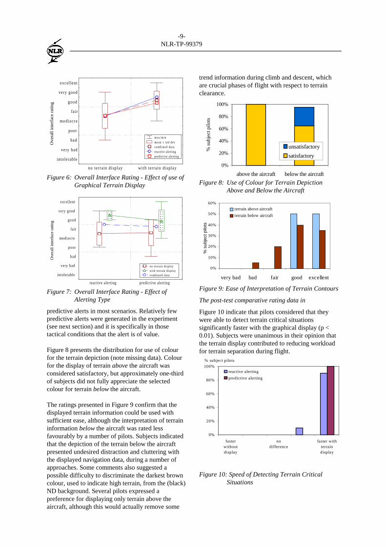
Figure 6: Overall Interface Rating - Effect of use ofGraphical Terrain Display
Ove
rall
inte
rfac
e ra
ting
��������������
������������������������
excellent
very good
good
fair
mediocre
poor
bad
very bad
intolerable
reactive alerting predictive alerting
no terra in displaywith terrain displayc o m b i n e d d a t a
Figure 7: Overall Interface Rating - Effect ofAlerting Type
predictive alerts in most scenarios. Relatively fewpredictive alerts were generated in the experiment(see next section) and it is specifically in thosetactical conditions that the alert is of value.
Figure 8 presents the distribution for use of colourfor the terrain depiction (note missing data). Colourfor the display of terrain above the aircraft wasconsidered satisfactory, but approximately one-thirdof subjects did not fully appreciate the selectedcolour for terrain below the aircraft.
The ratings presented in Figure 9 confirm that thedisplayed terrain information could be used withsufficient ease, although the interpretation of terraininformation below the aircraft was rated lessfavourably by a number of pilots. Subjects indicatedthat the depiction of the terrain below the aircraftpresented undesired distraction and cluttering withthe displayed navigation data, during a number ofapproaches. Some comments also suggested apossible difficulty to discriminate the darkest browncolour, used to indicate high terrain, from the (black)ND background. Several pilots expressed apreference for displaying only terrain above theaircraft, although this would actually remove some
trend information during climb and descent, whichare crucial phases of flight with respect to terrainclearance.
0%
20%
40%
60%
80%
100%
above the aircraft below the aircraft
% s
ubje
ct p
ilots
unsatisfactory
satisfactory
Figure 8: Use of Colour for Terrain DepictionAbove and Below the Aircraft
0%
10%
20%
30%
40%
50%
60%
very bad bad fair good excellent
% s
ubje
ct p
ilots
terrain above aircraft
terrain below aircraft
Figure 9: Ease of Interpretation of Terrain Contours
The post-test comparative rating data in
Figure 10 indicate that pilots considered that theywere able to detect terrain critical situationssignificantly faster with the graphical display (p <0.01). Subjects were unanimous in their opinion thatthe terrain display contributed to reducing workloadfor terrain separation during flight.
Figure 10: Speed of Detecting Terrain CriticalSituations
0%
20%
40%
60%
80%
100%
fasterwithoutdisplay
nodifference
faster withterraindisplay
reactive alerting
predictive alerting
% subject pilots

-10-NLR-TP-99379
Quantitative AnalysisA total of 140 scenarios were flown. The mainparameters of interests for the quantitative analysisfor each scenario included:- Perceived terrain awareness (crews were asked
whether they felt comfortable with respect toterrain clearance at the termination of runs);
- Crew recognition of unsafe vectors and/orcurrent terrain clearance;
- Terrain alert(s) generated;- The overall quality of the crew decision (safe vs.
unsafe consequences);- Compliance with the required SOP for escape
manoeuvres.For the purposes of this paper only a selection ofresults is presented. In the ensuing discussion, theterm “safe” refers specifically to collision withterrain and/or marginal terrain clearance indicated bya GPWS/TAWS alert.
Nominal scenariosScenarios 2-4 comprised a total of 60 evaluationtrials. As expected crew performance for all fourinterface types (display vs. no terrain display, andreactive vs. predictive alerting) was similar - allscenario outcomes being “safe”. Subjects clearlyfavoured the terrain display for conductingoperations in the terrain rich environments exposedto them.
Radar vectoring towards rising terrainFigure 11 presents an overview of scenario 5ainvolving radar vectoring towards rising terrain. Thescenario involved an engine failure shortly after take-off from Mexico City airport, which required animmediate return. While the engine failure wasintroduced to pose extra workload to the crew, theaircraft returned to the airport via radar vectors givenby the experiment ATC controller. Part of the radarvectoring involved flight towards rising terrain. Withthe terrain display, terrain critical situations did notarise. Subjects clearly recognised potential threats inadvance and requested alternative vectors (consistentwith subjective data in). The outcome was “safe” in100% of the runs with a display. Without the displaytwo-thirds of the scenarios involved an “unsafe”situation.
For the alternative scenario (to reduce learningeffect), the crew was initially briefed on a standardarrival routing into Mexico City. Radar vectors offthe standard routing were given to place the aircraftin the proximity of rising terrain. The results fromthis scenario (5b) are summarised in Figure 12. Fortythree percent of the crews without a terrain displayencountered an “unsafe” situation – terrain alert. All
runs with a terrain display resulted in “safe”outcomes.
10 crews were exposedto VISOS1 departure,
with engine failure nearVASOS waypoint
Were vectoredinto mountain,without crewnoticing risingterrain ahead.(scenario abortedbefore alert)
Passed mountainwith low margin.Crew declared toplace trust in ATCfor adequateterrain clearance.
Did not acceptvector into terrain.
Noticed possibleterrain collision,monitored terraindisplay andrequested othervector
2 crews withpredictive
terrain alerting
7 crews withterrain display
1 crew withreactive
terrain alerting
3 crews withoutterrain display
Figure 11: Crew Response to Terrain Criticalvectors by ATC Following Engine Failure
For all terrain vectoring scenarios combined (5a-b),the outcome for 100% of terrain display aidedscenarios was “safe”, whereas 50% of those withouta display resulted in an “unsafe” encounter. For thosecrews with a display, no predictive alerts weregenerated. It appears that the terrain display providedsufficient spatial awareness to prevent thedevelopment of conditions that would trigger apredictive alert. It is likely that subject behaviour(not uncommon for experiments of this type, seeRef.6-7) also played a role, e.g. often refusingdescents, requesting new vectors.
10 crews were exposedto COAPA arrival and
radar vectors into terrainbefore line-up on ILS
Crew or member felt UNEASYabout terrain separation
All felt EASY aboutterrain separation
7 crews without terrain display(4 reactive, 3 predictive alerting)
3 crews with terrain display(1 reactive, 2 predictive alerting)
all 3 crews
anticipated terrainalert or caution and
requested othervectors
3 crewspredictive alerting
“received” ambercaution”, requested
reclearance
3 crewreactive alerting
uncomfortable ormonitored raw dataasked reclearance
1 crewreactive alerting
did not acceptvector towardsrising terrain.
Figure 12: Crew Responses to Terrain Criticalvectors by ATC during Approachvectoring
Observations of crew behaviour during these twoscenarios clearly suggest that the graphical terraininformation significantly improved the “comfortlevel” of the crews during radar vectoring with non-standard routing. However, it was also observed

-11-NLR-TP-99379
during the high workload engine failure scenario, thatat least two subjects used the terrain display fornavigating away from significant terrain. (This wasdeduced from the communications in the flight deckand subsequent crew actions). When the terraindisplay was not available during these scenarios,observations suggest that subjects found it morechallenging to efficiently correlate their actualposition with the approach charts to verify sufficientterrain separation. Crew requests to ATC such as“state intentions” or revised clearances generallyoccurred earlier in those scenarios aided with aterrain display (consistent with subjective data in
Figure 10).
Incorrect altimeter setting/QNHThe QNH given to crews in scenarios 6a-b placed theaircraft to within 1000 ft of terrain. Results forscenario 6a are show in Figure 13. Three of the tencrews noticed the anomaly at the termination of therun. Note that in half of these cases (including theTAWS trials) the basic GPWS “too low terrain” alertwas generated and standard terrain recovery wasexecuted.
Scenario 6b was a challenging approach in a terrainrich area with a steep descent using LOC and DMEguidance to (overhead) the airport, followed by visualmanoeuvring including course reversal to therunaway. The vertical clearance during the approachwas sufficient to prevent alerts being generated, andnone of the ten crews exposed to this scenarionoticed the QNH anomaly. The outcome of all 6btrials was “safe”.
Figure 13: Altimeter Setting Error - Scenario 6a
Detection of terrain database errorsThe potential for erroneous terrain data and theintegrity issues of the onboard database have beenheavily debated in industry. Current systems aredeveloped on the basis that the information is
supplemental to the basic GPWS and that theintended use of terrain display is for “pilotawareness” only, not for “navigation” or “escapeguidance. There is also speculation in some quartersthat the terrain information presented is extremelycompelling and that a potential exists whereby thesystem may be inadvertently misused for navigation.Scenario 7b included a database error with incorrectterrain elevation for an area beside the arrival path,on the published Otumba 2 arrival into Mexico City.The display presented the mountain as being 2000 fthigher than actual. The crews were cleared todescend to an altitude such that the terrain would bepresented on the ND (under normal circumstances itwould not be displayed).
10 crews: OTUMBA arrival withterrain database error
4 crews:refused descend
or climbedhigher altitude
4 crews questioneddisplayed terrain info
4 crews:did not remark
or did notperceive conflict
6 crews:noticed high
terrain on display
2 crews:would not acceptdescent in reality
crewsmaintained
12000ft
Figure 14: Crew reaction to terrain databaseanomaly
Figure 14 indicates that 40% of the crews did notquestion the presentation of information that posed apotential terrain separation conflict. At thetermination of the scenario, when questioned aboutterrain separation, these crews indicated that they felt“comfortable” with respect to terrain separation.
In scenario 7a, a mountain located approximately 5NM north of the take-off runway was laterallydisplaced (within the TAWS database) below thepublished departure routing. It was therefore visibleon the ND below the departure route. Crews werealso in possession of the published SID that depictedthe correct terrain. None of the crews noticed thedatabase anomaly prior to or during take-off anddeparture, even though it was located below thedeparture route. An established procedure forbriefing about terrain database errors before takeoffwas not included in the experiment. Note that forsome airports it is not unusual to take-off towardshigh terrain. In today's operations, the assumption isthat following SOPs, SIDs and Climb Procedures willprovide the necessary terrain clearance if followed.
received “too lowterrain” alert
made terrainrecovery
3 crews notedQNH error
10 crews were exposed toOTUMBA arrival withaltimeter setting error
5 crewsbasic GPWS
5 crewsterrain display and forwardlook
refused descent to11000 ft
maintained ownsafe altitudes of atleast 12000ft
no terrain alertgenerated
suspected GS outon ILS approach,made VOR/DMEapproach andwent go-aroundat MDA becausenot visual
no terrain alertgenerated
no remarks
received terraincaution
adjusted descent
no remarks
11
11
12
3
-12-NLR-TP-99379
The combined data for scenarios 7a-b indicate that in70% of the cases, crews did not notice the anomalieson the terrain display.
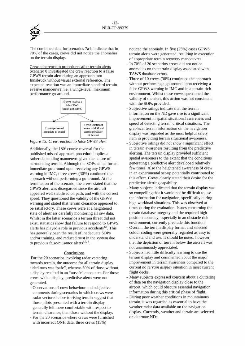
Crew adherence to procedures after terrain alertsScenario 8 investigated the crew reaction to a falseGPWS terrain alert during an approach intoInnsbruck without visual external reference. Theexpected reaction was an immediate standard terrainevasive manoeuvre, i.e. a wings-level, maximumperformance go-around.
7 crews performedimmediate go-around
3 crews continueddescent to MDA andquestioned validity
of the alert
10 crews received afalse GPWS
terrain alert in IMC
Figure 15: Crew reaction to false GPWS alert
Additionally, the 180º course reversal for thepublished missed approach procedure implies arather demanding manoeuvre given the nature ofsurrounding terrain. Although the SOPs called for animmediate go-around upon receiving any GPWSwarning in IMC, three crews (30%) continued theapproach without performing a go-around. At thetermination of the scenario, the crews stated that theGPWS alert was disregarded since the aircraftappeared well stabilised on path, and with the correctspeed. They questioned the validity of the GPWSwarning and stated that terrain clearance appeared tobe satisfactory. These crews were at a heightenedstate of alertness carefully monitoring all raw data.Whilst in the latter scenarios a terrain threat did notexist, statistics show that failure to respond to GPWSalerts has played a role in previous accidents1,3. Thishas generally been the result of inadequate SOPsand/or training, and reduced trust in the system dueto previous false/nuisance alerts1,3, 8.
Conclusions For the 20 scenarios involving radar vectoringtowards terrain, the outcome for all terrain displayaided runs was “safe”, whereas 50% of those withouta display resulted in an “unsafe” encounter. For thosecrews with a display, predictive alerts were notgenerated.- Observations of crew behaviour and subjective
comments during scenarios in which crews wereradar vectored close to rising terrain suggest thatthose pilots presented with a terrain displaygenerally felt more comfortable with respect toterrain clearance, than those without the display.
- For the 20 scenarios where crews were furnishedwith incorrect QNH data, three crews (15%)
noticed the anomaly. In five (25%) cases GPWSterrain alerts were generated, resulting in executionof appropriate terrain recovery manoeuvres.
- In 70% of 20 scenarios crews did not noticeanomalies on the terrain display associated withTAWS database errors.
- Three of 10 crews (30%) continued the approachwithout performing a go-around upon receiving afalse GPWS warning in IMC and in a terrain-richenvironment. Whilst these crews questioned thevalidity of the alert, this action was not consistentwith the SOPs provided.
- Subjective ratings indicate that the terraininformation on the ND gave rise to a significantimprovement in spatial situational awareness andspeed of detecting terrain critical situations. Thegraphical terrain information on the navigationdisplay was regarded as the most helpful safetyitem in providing terrain situational awareness.
- Subjective ratings did not show a significant effectin terrain awareness resulting from the predictivealerting. The terrain display provided sufficientspatial awareness to the extent that the conditionsgenerating a predictive alert developed relativelyfew times. Also the heightened awareness of crewin an experimental set-up potentially contributed tothis effect. Crews clearly stated their desire for thepredictive alerting capability.
- Many subjects indicated that the terrain display wasso compelling that it would not be difficult to usethe information for navigation, specifically duringhigh workload situations. This was observed attimes during the evaluation. Issues concerning theterrain database integrity and the required highposition accuracy, especially in an obstacle richenvironment, currently preclude this function.
- Overall, the terrain display format and selectedcolour coding were generally regarded as easy tounderstand and use. It should be noted, however,that the depiction of terrain below the aircraft wasnot unanimously appreciated.
- Subjects had little difficulty learning to use theterrain display and commented about the majorimprovement in terrain awareness compared to thecurrent no terrain display situation in most currentflight decks.
- Many subjects expressed concern about a clutteringof data on the navigation display close to theairport, which could obscure essential navigationinformation during this critical phase of flight.
- During poor weather conditions in mountainousterrain, it was regarded as essential to have theweather radar data available on the navigationdisplay. Currently, weather and terrain are selectedon alternate NDs.
-13-NLR-TP-99379
Recommendationsa) Product designers should ensure that terrain
information is distinguishable from other displayelements such as traffic, FMS flight path, dataand weather. The importance of backgroundterrain and terrain alerting information should bespecified relative to these other data on thedisplay. The use of colour should not result inthe erroneous interpretation of terraininformation. Means to deal with potential clutter,especially at low altitudes/during approach,should be addressed. Strategies to allow theflight crew to manipulate the shared display ofinformation may need to be provided.
b) States and operators should support theimplementation of TAWS as proposed by ICAO,FAA and the FSF CFIT/ALAR Task Force.
c) Operators should provide flight crews withadequate CFIT awareness and avoidance traininge.g. FSF CFIT Training Aid.
d) Operators employing TAWS/GPWS equipmentshould provide flight crews with the necessarySOPs and training. Correct terrain recoveryprocedures and limitations of the TAWS/GPWSsystem being utilised should be emphasised.Both initial and recurrent training should exposeflight crews to high workload scenarios thatdemonstrate navigation strategies independent ofthe TAWS display.
References1. Khatwa R, Roelen A L C, An Analysis of
Controlled-Flight-Into-Terrain (CFIT) Accidentsof Commercial Operators, 1988 Through 1994,National Aerospace Laboratory NLR,Amsterdam, FSF Flight Safety Digest, April-May1996.
2. Enders J H, et al, Airport Safety: A Study ofAccidents and Available Approach and LandingAids, FSF Flight Safety Digest, Alexandria, VA,March 1996.
3. Khatwa R, Helmreich R L, An Analysis OfCritical Factors During Approach & Landing inAccidents and Normal Flight, FSF 11th AnnualEuropean Aviation Safety Seminar, Amsterdam,March 1999.
4. SAE G-10, Human Interface Criteria for TerrainSeparation Assurance Display Technology, ARP5108, Warrendale, PA, 1997.
5. De Muynck R J, Khatwa R, OperationalImplications of Ground Collision AvoidanceSystems in Civil Transport Aircraft, NLR-CR-98325, National Aerospace Laboratory NLR,Amsterdam, the Netherlands, December 1998.
6. Kuchar J K, Hansman R J, Part-Task SimulatorEvaluation of Advanced Terrain Displays, SAEAerotech 93, Costa Mesa, CA, September 1993.
7. Kuchar J K, Hansman R J, An Exploratory Studyof Plan-View Terrain Displays for Air CarrierOperations, The International Journal of AviationPsychology, 3(1), pp. 39-54, 1993.
8. FSF, Killer in Aviation: FSF Task Force PresentsFacts About Approach-and-Landing andControlled-Flight-Into-Terrain Accidents, FlightSafety Digest, Alexandria, VA, November 1998-February 1999.