Embed Size (px)
Citation preview

Tel.: +420 572 537 111Fax: +420 575 537 910e---mail: [email protected]://www.evektor.cz
EVEKTOR --- AEROTECHNIK, a.s.Letecká 1384686 04 KunoviceCzech Republic
Copyright � 2005EVEKTOR --- AEROTECHNIK, a.s.
FLIGHT MANUAL
FOR
SPORTSTAR
ULTRALIGHT AIRPLANE
Serial number:
Registration mark:
Document number: S2005FMENKT
Date of issue: October 20, 2005
This manual must be on the airplane board during operation. This manual contains informationwhich must be provided to the pilot and also contains supplementary information provided by theairplane manufacturer --- Evektor --- Aerotechnik a.s.
This airplane must be operated in compliance with the information and limitations
stated in this manual.

FLIGHT MANUAL
Doc. No. S2005FMENKT
Section 0
Technical
Information
October 20, 2005 0---1
0. TECHNICAL INFORMATION
0.1 Log of Revisions
All revisions or supplements to this manual, except actual weighing data, are issued
in form of revisions, which will have new or changed pages as appendix and the
list of which is shown in the Log of Revisons table.
The new or changed text in the revised pages will be marked by means of black
vertical line on the left margin of page and the revision number and date will be
shown on the bottom margin of page.
Rev.No.
AffectedSection
AffectedPages
Date Approved DateDate ofinsertion
Signature

FLIGHT MANUAL
Doc. No. S2005FMENKT
Section 0
Technical
Information
October 20, 20050---2
Rev.No.
SignatureDate ofinsertion
DateApprovedDateAffectedPages
AffectedSection

FLIGHT MANUAL
Doc. No. S2005FMENKT
Section 0
Technical
Information
October 20, 2005 0---3
0.2 List of Effective Pages
Section Page Date Section Page Date
0 0---1 October 20, 2005 3---5 October 20, 2005
0---2 October 20, 2005 3---6 October 20, 2005
0---3 October 20, 2005 3---7 October 20, 2005
0---4 October 20, 2005 3---8 October 20, 2005
0---5 October 20, 2005 3---9 October 20, 2005
0---6 October 20, 2005 3---10 October 20, 2005
1 1---1 October 20, 2005
1---2 October 20, 2005
1---3 October 20, 2005
1---4 October 20, 2005 4 4---1 October 20, 2005
1---5 October 20, 2005 4---2 October 20, 2005
1---6 October 20, 2005 4---3 October 20, 2005
1---7 October 20, 2005 4---4 October 20, 2005
1---8 October 20, 2005 4---5 October 20, 2005
4---6 October 20, 2005
4---7 October 20, 2005
4---8 October 20, 2005
2 2---1 October 20, 2005 4---9 October 20, 2005
2---2 October 20, 2005 4---10 October 20, 2005
2---3 October 20, 2005 4---11 October 20, 2005
2---4 October 20, 2005 4---12 October 20, 2005
2---5 October 20, 2005 4---13 October 20, 2005
2---6 October 20, 2005 4---14 October 20, 2005
2---7 October 20, 2005
2---8 October 20, 2005
2---9 October 20, 2005
2---10 October 20, 2005 5 5---1 October 20, 2005
5---2 October 20, 2005
5---3 October 20, 2005
5---4 October 20, 2005
3 3---1 October 20, 2005 5---5 October 20, 2005
3---2 October 20, 2005 5---6 October 20, 2005
3---3 October 20, 2005 5---7 October 20, 2005
3---4 October 20, 2005 5---8 October 20, 2005

FLIGHT MANUAL
Doc. No. S2005FMENKT
Section 0
Technical
Information
October 20, 20050---4
Section DatePageSectionDatePage
5---9 October 20, 2005 8 8---1 October 20, 2005
5---10 October 20, 2005 8---2 October 20, 2005
5---11 October 20, 2005 8---3 October 20, 2005
5---12 October 20, 2005 8---4 October 20, 2005
5---13 October 20, 2005 8---5 October 20, 2005
5---14 October 20, 2005 8---6 October 20, 2005
5---15 October 20, 2005 8---7 October 20, 2005
8---8 October 20, 2005
6 6---1 October 20, 2005
6---2 October 20, 2005
6---3 October 20, 2005 9 9---1 October 20, 2005
6---4 October 20, 2005 9---2 October 20, 2005
6---5 October 20, 2005
6---6 October 20, 2005
6---7 October 20, 2005
6---8 October 20, 2005
7 7---1 October 20, 2005
7---2 October 20, 2005
7---3 October 20, 2005
7---4 October 20, 2005
7---5 October 20, 2005
7---6 October 20, 2005
7---7 October 20, 2005
7---8 October 20, 2005
7---9 October 20, 2005
7---10 October 20, 2005
7---11 October 20, 2005
7---12 October 20, 2005
7---13 October 20, 2005
7---14 October 20, 2005
7---15 October 20, 2005
7---16 October 20, 2005

FLIGHT MANUAL
Doc. No. S2005FMENKT
Section 0
Technical
Information
October 20, 2005 0---5
0.3 Table of Contents
Section
General 1
Limitations 2
Emergency procedures 3
Normal procedures 4
Performance 5
Weight and balance 6
Airplane and system description 7
Airplane handling, servicing and maintenance 8
Supplements 9

FLIGHT MANUAL
Doc. No. S2005FMENKT
Section 0
Technical
Information
October 20, 20050---6
Intentionally left blank
FLIGHT MANUAL
Doc. No. S2005FMENKT
Section 1
General
October 20, 2005 1---1
CONTENTS
1. GENERAL
1.1 Introduction 1---3. . . . . . . . . . . . . . . . . . . . . . . . . . . . . . . . . . . . . . . . . . . . . . . . . .
1.2 Certification basis 1---3. . . . . . . . . . . . . . . . . . . . . . . . . . . . . . . . . . . . . . . . . . . .
1.3 Warnings, cautions, notes 1---3. . . . . . . . . . . . . . . . . . . . . . . . . . . . . . . . . . . . .
1.4 Descriptive data 1---4. . . . . . . . . . . . . . . . . . . . . . . . . . . . . . . . . . . . . . . . . . . . . .
1.4.1 Airplane description 1---4. . . . . . . . . . . . . . . . . . . . . . . . . . . . . . . . . . . . . . . . . . . .
1.4.2 Powerplant 1---4. . . . . . . . . . . . . . . . . . . . . . . . . . . . . . . . . . . . . . . . . . . . . . . . . . . .
1.4.3 Main technical data 1---4. . . . . . . . . . . . . . . . . . . . . . . . . . . . . . . . . . . . . . . . . . . .
1.4.4 Three---view drawing 1---5. . . . . . . . . . . . . . . . . . . . . . . . . . . . . . . . . . . . . . . . . . .
1.5 Definitions and abbreviations 1---6. . . . . . . . . . . . . . . . . . . . . . . . . . . . . . . . . .

FLIGHT MANUAL
Doc. No. S2005FMENKT
Section 1
General
October 20, 20051---2
Intentionally left blank

FLIGHT MANUAL
Doc. No. S2005FMENKT
Section 1
General
October 20, 2005 1---3
1.1 Introduction
This Flight manual has been prepared to provide pilots and instructors with informa-
tion for safe and efficient operation of the SPORTSTAR airplane. It also contains sup-
plementary information considered to be important by the airplane manufacturer.
1.2 Certification basis
This type of airplane meets Standard Specification for Airworthiness of Light Sport
Aircraft.
1.3 Warnings, cautions, notes
The following informations apply to warnings, cautions and notes used in the Flight
manual:
WARNING
MEANS THAT NON---OBSERVATIONS OF THE
CORRESPONDING PROCEDURE LEADS TO AN
IMMEADIATE OR IMPORTENT DEGRADATION OF
THE FLIGHT SAFETY.
CAUTION
MEANS THAT NON---OBSERVATIONS OF THE COR-
RESPONDINGPROCEDURE LEADSTOAMINOROR
TO A MORE OR LESS LONG TERM DEGRADATION
OF THE FLIGHT SAFETY.
NOTE
Draws the attention to any special item not directly re-
lated to safety but which is important or unusual.

FLIGHT MANUAL
Doc. No. S2005FMENKT
Section 1
General
October 20, 20051---4
1.4 Descriptive data
1.4.1 Airplane description
SPORTSTAR airplane is an all---metal low---wing of semimonocoque structure with
two side by side seats and three---wheel landing gear
For further description see chapt. 7 --- Airplane and system description.
1.4.2 Powerplant
The standard powerplant consists of ROTAX 912 S engine and WOODCOMP
KLASSIC 170/3/R propeller.
For further description see section 7 --- Airplane and system description.
If installed other propeller type --- see section 9 --- Supplements.
1.4.3 Main technical data
Wing
Span 28.37 ft 8.646 m. . . . . . . . . . . . . . . . . . . . . . . . . . . . . . . . . . . . . . . . .
Area 112.7 sq.ft 10.47 sq.m. . . . . . . . . . . . . . . . . . . . . . . . . . . . . . . . . . . . . . . . .
MAC depth 4.1 ft 1.25 m. . . . . . . . . . . . . . . . . . . . . . . . . . . . . . . . . . .
Wing loading 10.76 lbs/sq.ft 52.53 kg/sq.m. . . . . . . . . . . . . . . . . . . . . . . . . . . . . . . . . .
Aileron --- area 2.62 sq.ft 0.25 sq.m. . . . . . . . . . . . . . . . . . . . . . . . . . . . . . . .
Flap --- area 5.60 sq.ft 0.52 sq.m. . . . . . . . . . . . . . . . . . . . . . . . . . . . . . . . . . .
Fuselage
length 19.62 ft 5.980 m. . . . . . . . . . . . . . . . . . . . . . . . . . . . . . . . . . . . . . . .
width 3.55 ft 1.082 m. . . . . . . . . . . . . . . . . . . . . . . . . . . . . . . . . . . . . . . . .
height 7.66 ft 2.335 m. . . . . . . . . . . . . . . . . . . . . . . . . . . . . . . . . . . . . . . .
cockpit canopy max. width 3.87 ft 1.180 m. . . . . . . . . . . . . . . . . . . . .
Horizontal tail unit
Span 8.20 ft 2.50 m. . . . . . . . . . . . . . . . . . . . . . . . . . . . . . . . . . . . . . . . .
HTU Area 20.88 sq.ft 1.94 sq.m. . . . . . . . . . . . . . . . . . . . . . . . . . . . . . . . . . . .
Elevator area 8.40 sq.ft 0.78 sq.m. . . . . . . . . . . . . . . . . . . . . . . . . . . . . . . . . .
Vertical tail unit
Height 4.07 ft 1.24 m. . . . . . . . . . . . . . . . . . . . . . . . . . . . . . . . . . . . . . .
VTU Area 10.76 sq.ft 1.00 sq.m. . . . . . . . . . . . . . . . . . . . . . . . . . . . . . . . . . . . .
Rudder area 4.31 sq.ft 0.40 sq.m. . . . . . . . . . . . . . . . . . . . . . . . . . . . . . . . . .
Landing gear
Wheel track 6.12 ft 1.865 m. . . . . . . . . . . . . . . . . . . . . . . . . . . . . . . . . . .
Wheel base 4.43 ft 1.350 m. . . . . . . . . . . . . . . . . . . . . . . . . . . . . . . . . . .
Main and nose landing gear wheel diameter 14 in 350 mm. . . . . .

FLIGHT MANUAL
Doc. No. S2005FMENKT
Section 1
General
October 20, 2005 1---5
1.4.4 Three---view drawing
Figure 1-1

FLIGHT MANUAL
Doc. No. S2005FMENKT
Section 1
General
October 20, 20051---6
1.5 Definitions and abbreviations
NOTE
The abbreviations on placards in the airplane cockpit,
are printed in BOLD CAPITAL LETTERS in the text ofthis Flight manual.
ACCU accumulator
ALT ENC encoding altimeter
ATC air traffic control
bar bar 1 bar = 100 kPa
BEACON anti---collision beacon
˚C Celsius degree
CAS calibrated airspeed
CLOCK aircraft clock
ft foot 1 ft = 0.305 m
GPS global positioning system
HTU horizontal tail unit
IAS indicated airspeed
IC intercom
IFR instrument flight rules
ISA international standard atmosphere
kg kilogram
KIAS indicatedair speed in knots
KCAS calibrated airspeed in knots
mph mile per hour
mph CAS indicated airspeed in miles per hour
km/h CAS calibrated airspeed in km/h
kts knots 1 kt = 1.852 km/h
litres litre
lbs pounds 1 lb = 0.45 kg
m meter
MAC mean aerodynamical chord
max. maximum
min. minimum or minute
mm milimeter
m/s meter per second
OAT outside air temperature
OFF system is switched off or control element is in off---position
ON system is switched on or control element is in on---position
Pa pascal 1Pa = 1N/m2

FLIGHT MANUAL
Doc. No. S2005FMENKT
Section 1
General
October 20, 2005 1---7
PSI pound per sq.in (1PSI = 6.89 kPa)
RPM revolutions per minute
RWY runway
sq.ft foot squared
sq.m meter squared
VA manoeuvring airspeed
VFE maximum flap extended speed --- flaps in 50˚ position
VFR visibility flight rules
VLOF airplane lift---off speed
V---METER voltmeter
VNE never exceed speed
VNO maximum structural cruising speed
VSO stall speed with wing flaps in 50˚ position
VS1 stall speed with wing flaps in 0˚ position
VTU vertical tail unit
VX best angle---of---climb speed
VY best rate---of---climb speed
XPDR transponder

FLIGHT MANUAL
Doc. No. S2005FMENKT
Section 1
General
October 20, 20051---8
Intentionally left blank

FLIGHT MANUAL
Doc. No. S2005FMENKT
Section 2
Limitations
October 20, 2005 2---1
CONTENTS
2. LIMITATIONS
2.1 Introduction 2---3. . . . . . . . . . . . . . . . . . . . . . . . . . . . . . . . . . . . . . . . . . . . . . . . . .
2.2 Airspeed 2---3. . . . . . . . . . . . . . . . . . . . . . . . . . . . . . . . . . . . . . . . . . . . . . . . . . . . .
2.3 Airspeed indicator marking 2---3. . . . . . . . . . . . . . . . . . . . . . . . . . . . . . . . . . . .
2.4 Powerplant 2---4. . . . . . . . . . . . . . . . . . . . . . . . . . . . . . . . . . . . . . . . . . . . . . . . . . .
2.5 Powerplant instrument marking 2---5. . . . . . . . . . . . . . . . . . . . . . . . . . . . . . . .
2.6 Miscellaneous instrument marking 2---5. . . . . . . . . . . . . . . . . . . . . . . . . . . . .
2.7 Weight 2---5. . . . . . . . . . . . . . . . . . . . . . . . . . . . . . . . . . . . . . . . . . . . . . . . . . . . . . .
2.8 Centre of gravity 2---6. . . . . . . . . . . . . . . . . . . . . . . . . . . . . . . . . . . . . . . . . . . . . .
2.9 Approved manoeuvres 2---6. . . . . . . . . . . . . . . . . . . . . . . . . . . . . . . . . . . . . . . .
2.10Manoeuvring load factors 2---6. . . . . . . . . . . . . . . . . . . . . . . . . . . . . . . . . . . . . .
2.11 Flight crew 2---6. . . . . . . . . . . . . . . . . . . . . . . . . . . . . . . . . . . . . . . . . . . . . . . . . . .
2.12 Kinds of operation 2---7. . . . . . . . . . . . . . . . . . . . . . . . . . . . . . . . . . . . . . . . . . . .
2.13 Fuel 2---8. . . . . . . . . . . . . . . . . . . . . . . . . . . . . . . . . . . . . . . . . . . . . . . . . . . . . . . . . .
2.14Oil 2---8. . . . . . . . . . . . . . . . . . . . . . . . . . . . . . . . . . . . . . . . . . . . . . . . . . . . . . . . . . .
2.15Maximum number of passengers 2---8. . . . . . . . . . . . . . . . . . . . . . . . . . . . . . .
2.16Other limitations 2---9. . . . . . . . . . . . . . . . . . . . . . . . . . . . . . . . . . . . . . . . . . . . . .
2.17 Limitation placards 2---9. . . . . . . . . . . . . . . . . . . . . . . . . . . . . . . . . . . . . . . . . . . .

FLIGHT MANUAL
Doc. No. S2005FMENKT
Section 2
Limitations
October 20, 20052---2
Intentionally left blank

FLIGHT MANUAL
Doc. No. S2005FMENKT
Section 2
Limitations
October 20, 2005 2---3
2.1 Introduction
Section 2 contains operation limitation, instrument marking and basic placards
necessary for safe operation of airplane and its engine, standard systems and
equipment.
Limitation for optional systems and equipment are stated in section 9 --- Supple-
ments.
2.2 Airspeed
Airspeed limitations and their meaning for operation are stated in the table below:
Speed KIAS mph IAS Meaning
VNE Never exceed speed 146 168Do not exceed this speedin any operation.
VNOMaximum structural cruis-ing speed
103 118
Do not exceed thisspeed, with exception offlight in smooth air, andeven then only with in-creased caution.
VA Manoeuvring speed 86 99
Do not make full orabrupt control movementabove this speed, be-cause under certain con-ditions the aircraft may beoverstressed by full con-trol movement.
VFE Maximum flap extendedspeed
70 81Do not exceed this speedwith the given flap setting.
2.3 Airspeed indicator marking
Airspeed indicator markings and their colour---code significance are shown in the
table below:
MarkingRange
MeaningMarkingKIAS mph IAS
Meaning
Red line 37 43VS0 at maximum weight (flaps in land-ing position 50˚)
White arc 37 --- 70 43 --- 81
Operating range with extended flaps.
Lower limit--- VS0 at maximum weight(flaps 50˚)
Upper limit --- VFE

FLIGHT MANUAL
Doc. No. S2005FMENKT
Section 2
Limitations
October 20, 20052---4
Marking MeaningRange
Marking Meaningmph IASKIAS
Green arc 42 --- 103 49 --- 118
Normal operation range
Lower limit --- VS1 at maximumweight (flaps 0˚)
Upper limit --- VNO
Yellow arc 103 --- 146 118 --- 168Manoeuvres must be conducted withcaution and only in smooth air
Red line 146 168Maximum speed for all operations ---VNE.
2.4 Powerplant
Engine manufacturer: Bombardier---Rotax GMBH
Engine type: ROTAX 912 S
Power: maximum take---off 100 HP / 73.5 kW
maximum continuous 93.8 HP / 69.0 kW
Engine speed: maximum take---off 5800 RPM max. 5 minutes
maximum continuous 5500 RPM
idle 1400 RPM
Cylinder headtemperature:
maximum 135 ˚C 275 ˚F
Oil temperature: maximum 130 ˚C 266 ˚F
optimum operation 90 --- 110 ˚C 190 --- 230 ˚F
Oil pressure: maximum 7 bar 102 PSI
minimum 0.8 bar 12 PSI
optimum operation 2 --- 5 bar 29 --- 73 PSI
Fuel pressure: minimum 0.15 bar 2.2 PSI
Fuel grades: see 2.13, page 2---8
Oil grades: see 2.14, page 2---8
Reducer gear ratio: 2.43 : 1
Propeller manufacturer: WOODCOMP s.r.o.
Propeller type: KLASSIC 170/3/R
3 blade, composite, on---ground adjustable
Propeller diameter: 68 in 1700 mm
Maximum prop speed: 2600 RPM
NOTE
If installed a different propeller type --- see section 9 ---Supplements for propeller limitations.

FLIGHT MANUAL
Doc. No. S2005FMENKT
Section 2
Limitations
October 20, 2005 2---5
2.5 Powerplant instrument marking
The colour---code of instruments is shown in the following table:
Red line Green arc Yellow arc Red line
Instrument UnitsLower limit
Normaloperationrange
Cautionrange
Upper limit
RPM indicator RPM --- 1400 ÷ 5500 5500 ÷ 5800 5800
Oil temperatureindicator
˚C --- 90 ÷ 11050 ÷ 90
110 ÷ 130130
Oil temperatureindicator
˚F --- 190 ÷ 230120 ÷ 190
230 ÷ 266266
Oil pressure in-dicator
bar 0.8 2 ÷ 50.8 ÷ 2
5 ÷ 77
Oil pressure in-dicator
PSI 12 29 ÷ 7312 ÷ 29
73 ÷ 102102
CHT indicator ˚C --- --- --- 135
CHT indicator ˚F --- --- --- 275
2.6 Miscellaneous instrument marking
There are not other instruments with colour marking.
2.7 Weight
Empty weight (standard equipment) 695 lbs ± 2 % 315 kg ± 2 %. . . . . . . . . . .
Maximum take---off weight 1213 lbs 550 kg. . . . . . . . . . . . . . . . . . . .
Maximum landing weight 1213 lbs 550 kg. . . . . . . . . . . . . . . . . . . . .
Maximum weight in baggage compartment 55 lbs 25 kg. . . . .
WARNING
DO NOT EXCEEDMAXIMUMWEIGHTS! THEIR EX-
CEEDING LEADS TO AIRPLANE OVERLOADING
AND TO DEGRADATION OF FLIGHT CHARACTER-
ISTICS AND DETERIORATION OF MANOEUVRA-
BILITY.

FLIGHT MANUAL
Doc. No. S2005FMENKT
Section 2
Limitations
October 20, 20052---6
2.8 Centre of gravity
Empty airplane C.G. position (standard equipment) 20 ± 2 %MAC. . . . . . . . . . .
Operating C.G. range 20 to 34 %MAC. . . . . . . . . . . . . . . . . . . . . . . . . . . . . . . . . . . . .
Reference datum is the wing leading edge.
2.9 Approved manoeuvres
SPORTSTAR airplane is approved to perform the following manoeuvres:
--- steep turns up to bank angle of 60°
--- climbing turns
--- lazy eights
--- stalls (except for steep stalls)
--- normal flight manoeuvres
WARNING
AEROBATICS AS WELL AS INTENTIONAL SPINS
ARE PROHIBITED !
2.10 Manoeuvring load factors
Maximum positive load factor 4.0. . . . . . . . . . . . . . . . . . . . . . . . . . . . . .
Maximum negative load factor ---2.0. . . . . . . . . . . . . . . . . . . . . . . . . . . . .
2.11 Flight crew
Minimum crew 1 pilot. . . . . . . . . . . . . . . . . . . . . . . . . . . . . . . . . . . . . . . . . . .
Minimum weight of crew 121 lbs 55 kg. . . . . . . . . . . . . . . . . . . . . .
Maximum weight of crew acc. to point 6.3. . . . . . . . . . . . . . . . . . . . . . . . . . . . . . . . . .
WARNING
DO NOT EXCEED MAXIMUM WEIGHTS! THEIR EX-
CEEDING LEADS TOAIRPLANEOVERLOADINGAND
TO DEGRADATION OF FLIGHT CHARACTERISTICS
AND DETERIORATION OF MANOEUVRABILITY.

FLIGHT MANUAL
Doc. No. S2005FMENKT
Section 2
Limitations
October 20, 2005 2---7
2.12 Kinds of operation
Only daylight flights are allowed according to VFR.
WARNING
NIGHT FLIGHTS ACCORDING TO VFR, FLIGHTS
ACCORDING TO IFR (BY INSTRUMENTS) AND IN-
TENTIONAL FLIGHTS UNDER ICINGCONDITIONS
ARE PROHIBITED.
Instruments and equipment for daylight flights according to VFR :
1 Airspeed indicator (the colour marking according to par. 2.3)
1 Sensitive barometric altimeter
1 Magnetic compass
1 Fuel gauge indicator
1 Oil temperature indicator
1 Oil pressure indicator
1 Cylinder head temperature indicator
1 Engine speed indicator
1 Safety harness for every used seat
CAUTION
ADDITIONAL EQUIPMENT NECESSARY FOR AIR-
PLANE OPERATION IS GIVEN IN APPROPRIATE
OPERATION REGULATIONOF AIRPLANE OPERA-
TOR’S COUNTRY.

FLIGHT MANUAL
Doc. No. S2005FMENKT
Section 2
Limitations
October 20, 20052---8
2.13 Fuel
Fuel tank volume (each) 15.85 U.S. gallons 60 litres. . . . . . . . . . . . . . . . . . . . . .
Total 31.7 U.S. gallons 120 litres. . . . . . . . . . . . . . . . . . . . . . . . . . . . . . . . . . . . . . . . .
Usable fuel 31.2 U.S. gallons 118 litres. . . . . . . . . . . . . . . . . . . . . . . . . . . . . . . . .
Unusable fuel 0.5 U.S. gallons 2.0 litres. . . . . . . . . . . . . . . . . . . . . . . . . . . . . . .
(0.25 USGal/1 liter per tank)
NOTE
It is not recommended to fully tank the fuel tanks.Due to fuel thermal expansion keep about 2.11U.S.gallons (8.0 litres) of free space in the tank to preventfuel bleed through the vents in the wing tips thus pre-venting environmental contamination. This should beadhered especially when cold fuel from an under-ground tank is tanked.
Approved fuel grades:
--- automotive petrol with min RON 95
--- EN 228 Premium
--- EN 228 Premium plus
--- AVGAS 100 LL
Due to higher lead content in AVGAS, the wear of valve seats and deposits in the
combustion chamber and lead sediments in the lubrication system will increase.
Therefore, use AVGAS only if you encouter problem with vapour lock or if the
other fuel types are not available
For other suitable fuel types refer to the engine Operator’s Manual
NOTE
Use only fuel suitable for the respective climatic zone.
Risk of vapour formation if usingwinter fuel for summer
operation.
2.14 Oil
Performance classification SF, SG according to API
Oil volume:
--- minimum 0.53 U.S. gallons 2.0 litres. . . . . . . . . . . . . . . . . . . . . . . . . . . . . . . . .
--- maximum 0.79 U.S. gallons 3.0 litres. . . . . . . . . . . . . . . . . . . . . . . . . . . . . . . .
2.15 Maximum number of passengers
Maximum number of passengers including pilot 2.

FLIGHT MANUAL
Doc. No. S2005FMENKT
Section 2
Limitations
October 20, 2005 2---9
2.16 Other limitations
--- SMOKING IS PROHIBITED on the airplane board.
2.17 Limitation placards
The following placard is located on the instrument panel:
The following placard is located in the baggage compartment:
The following placards are located on the tilting canopy:
or
or
NOTE
The values stated on the placard “LOAD LIMITS” arevalid for the empty weight of the airplane with standard
equipment. The placard with values valid for the actualempty weight of the airplane will be placed in the cock-pit.
Other placards and labels are shown in Maintenance
Manual.

FLIGHT MANUAL
Doc. No. S2005FMENKT
Section 2
Limitations
October 20, 20052---10
Intentionally left blank

FLIGHT MANUAL
Doc. No. S2005FMENKT
Section 3
Emergency
Procedures
October 20, 2005 3---1
CONTENTS
3. EMERGENCY PROCEDURES
3.1 Introduction 3---3. . . . . . . . . . . . . . . . . . . . . . . . . . . . . . . . . . . . . . . . . . . . . . . . . .
3.2 Speeds for performing emergency procedures 3---3. . . . . . . . . . . . . . . . . .
3.3 Engine failure 3---3. . . . . . . . . . . . . . . . . . . . . . . . . . . . . . . . . . . . . . . . . . . . . . . . .
3.3.1 Engine failure at take---off run 3---3. . . . . . . . . . . . . . . . . . . . . . . . . . . . . . . . . . .
3.3.2 Engine failure at take---off 3---3. . . . . . . . . . . . . . . . . . . . . . . . . . . . . . . . . . . . . . .
3.3.3 Engine failure at flight 3---4. . . . . . . . . . . . . . . . . . . . . . . . . . . . . . . . . . . . . . . . . .
3.4 Engine starting at flight 3---4. . . . . . . . . . . . . . . . . . . . . . . . . . . . . . . . . . . . . . . .
3.5 Engine fire 3---5. . . . . . . . . . . . . . . . . . . . . . . . . . . . . . . . . . . . . . . . . . . . . . . . . . .
3.5.1 Fire on the ground 3---5. . . . . . . . . . . . . . . . . . . . . . . . . . . . . . . . . . . . . . . . . . . . .
3.5.2 Fire during take---off 3---5. . . . . . . . . . . . . . . . . . . . . . . . . . . . . . . . . . . . . . . . . . . .
3.5.3 Fire at flight 3---5. . . . . . . . . . . . . . . . . . . . . . . . . . . . . . . . . . . . . . . . . . . . . . . . . . .
3.6 Fire in the cockpit (if manual extinguisher available aboard) 3---6. . . . . .
3.7 Gliding flight 3---7. . . . . . . . . . . . . . . . . . . . . . . . . . . . . . . . . . . . . . . . . . . . . . . . . .
3.8 Emergency landing 3---7. . . . . . . . . . . . . . . . . . . . . . . . . . . . . . . . . . . . . . . . . . .
3.8.1 Emergency landing --- with non---operating engine 3---7. . . . . . . . . . . . . . . . .
3.8.2 Safety landing--- with engine operating 3---7. . . . . . . . . . . . . . . . . . . . . . . . . . .
3.8.3 Landing with burst tire 3---8. . . . . . . . . . . . . . . . . . . . . . . . . . . . . . . . . . . . . . . . . .
3.8.4 Landing with damaged landing gear 3---8. . . . . . . . . . . . . . . . . . . . . . . . . . . . .
3.9 Unintentional spin recovery 3---8. . . . . . . . . . . . . . . . . . . . . . . . . . . . . . . . . . . .
3.10Other emergency procedures 3---9. . . . . . . . . . . . . . . . . . . . . . . . . . . . . . . . . .
3.10.1Vibration 3---9. . . . . . . . . . . . . . . . . . . . . . . . . . . . . . . . . . . . . . . . . . . . . . . . . . . . . .
3.10.2Carburettor icing 3---9. . . . . . . . . . . . . . . . . . . . . . . . . . . . . . . . . . . . . . . . . . . . . . .

FLIGHT MANUAL
Doc. No. S2005FMENKT
Section 3
Emergency
Procedures
October 20, 20053---2
Intentionally left blank

FLIGHT MANUAL
Doc. No. S2005FMENKT
Section 3
Emergency
Procedures
October 20, 2005 3---3
3.1 Introduction
Section 3 describes operations and procedures for emergency situation solutions
that could possibly occur during airplane operation.
3.2 Speeds for performing emergency procedures
Airspeed for the best gliding ratio (flaps retracted) 57 KIAS (66 mph IAS)
Precautionary landing(engine running, flaps in landing position --- 50˚) 48 KIAS (55 mph IAS)
Emergency landing(engine stopped, flaps in landing position --- 50˚) 48 KIAS (55 mph IAS)
3.3 Engine failure
3.3.1 Engine failure at take---off run
1. THROTTLE lever idle. . . . . . . . . . . . . . . . . . . . . . . . .
2. Brakes as necessary. . . . . . . . . . . . . . . . . . . . . . . . . . . . . . . . . .
3. FUEL SELECTOR OFF. . . . . . . . . . . . . . . . . . . . . . . .
4. Ignition OFF. . . . . . . . . . . . . . . . . . . . . . . . . . . . . . . . . .
5. MASTER SWITCH OFF. . . . . . . . . . . . . . . . . . . . . . . .
3.3.2 Engine failure at take---off
1. Gliding speed:
Flaps in take---off position (15˚) 52 KIAS (60 mph IAS). . . . . . . . . . . . .
Flaps retracted (0˚) 57 KIAS (66 mph IAS). . . . . . . . . . . . . . . . . . . . . . .
2. Altitude:
--- Land in take---off direction if below 150 ft:
--- Choose an area for landing if above 150 ft:
3. THROTTLE lever idle. . . . . . . . . . . . . . . . . . . . . . . . .
4. Flaps as necessary. . . . . . . . . . . . . . . . . . . . . . . . . . . . . . . . . . . .
5. FUEL SELECTOR OFF. . . . . . . . . . . . . . . . . . . . . . . .
6. Ignition OFF. . . . . . . . . . . . . . . . . . . . . . . . . . . . . . . . . .
7. MASTER SWITCH OFF. . . . . . . . . . . . . . . . . . . . . . . .
8. After touch down brake according to need. . . . . . . . . . . . . . . . . . . . . . . . .

FLIGHT MANUAL
Doc. No. S2005FMENKT
Section 3
Emergency
Procedures
October 20, 20053---4
3.3.3 Engine failure at flight
1. Gliding speed 57 KIAS (66 mph IAS). . . . . . . . . . . . . . . . . . . . . . . . . . . .
2. Altitude take a decision and carry out:. . . . . . . . . . . . . . . . . . . . . . . . . . . . . . . . . .
--- Engine starting at flight --- paragraph 3.4, page 3---4
--- Emergency landing --- paragraph 3.8.1, page 3---7
3.4 Engine starting at flight
NOTE
It is possible to to start the engine by means of thestarter within the whole range of operation speeds aswell as flight altitudes. The engine started up immedi-ately after switching the ignition to START position.
If the propeller is shut down, the altitude loss duringengine starting can reach up to 1000 ft.
1. Gliding speed 57 KIAS (66 mph IAS). . . . . . . . . . . . . . . . . . . . . . . . . . . .
2. Altitude check. . . . . . . . . . . . . . . . . . . . . . . . . . . . . . . . . .
3. MASTER SWITCH ON. . . . . . . . . . . . . . . . . . . . . . . .
4. Unnecessary electrical equipment switch off. . . . . . . . . .
5. FUEL SELECTOR LEFT. . . . . . . . . . . . . . . . . . . . . . . .
6. Choke as necessary. . . . . . . . . . . . . . . . . . . . . . . . . . . . . . . . . . .
7. THROTTLE lever idle. . . . . . . . . . . . . . . . . . . . . . . . .
The propeller is rotating:
8. Ignition BOTH. . . . . . . . . . . . . . . . . . . . . . . . . . . . . . . . . .
The propeller is not rotating:
9. Ignition START. . . . . . . . . . . . . . . . . . . . . . . . . . . . . . . . . .
10. If engine starting does not occur, increase gliding speed up to 108 KIAS
(124 mph IAS) (see NOTE), so that air--- flow turns the propeler and engine
starting occurs.
11. Ignition BOTH. . . . . . . . . . . . . . . . . . . . . . . . . . . . . . . . . .
12. If engine starting is unsuccessful, then continue according to paragraph 3.8.1
Emergency landing.

FLIGHT MANUAL
Doc. No. S2005FMENKT
Section 3
Emergency
Procedures
October 20, 2005 3---5
3.5 Engine fire
3.5.1 Fire on the ground
1. FUEL SELECTOR OFF. . . . . . . . . . . . . . . . . . . . . . . .
2. Brakes brake. . . . . . . . . . . . . . . . . . . . . . . . . . . . . . . . . .
3. THROTTLE lever full. . . . . . . . . . . . . . . . . . . . . . . . .
4. COCKPIT HEATING knob close. . . . . . . . . . . . . . . . .
5. HOT AIR knob (if installed) close. . . . . . . . . . . . . . . . .
6. Ignition OFF. . . . . . . . . . . . . . . . . . . . . . . . . . . . . . . . . .
7. MASTER SWITCH OFF. . . . . . . . . . . . . . . . . . . . . . . .
8. Airplane leave. . . . . . . . . . . . . . . . . . . . . . . . . . . . . . . . .
9. Manual extinguisher (if available) use. . . . . . . . . . .
3.5.2 Fire during take---off
1. FUEL SELECTOR OFF. . . . . . . . . . . . . . . . . . . . . . . .
2. THROTTLE lever full. . . . . . . . . . . . . . . . . . . . . . . . .
3. HOT AIR knob (if installed) close. . . . . . . . . . . . . . . . .
4. Gliding speed 52 KIAS (60 mph IAS). . . . . . . . . . . . . . . . . . . . . . . . . . . .
5. Ignition OFF. . . . . . . . . . . . . . . . . . . . . . . . . . . . . . . . . .
6. Land
7. MASTER SWITCH OFF immediately after. . . . . . . . . . . . . . . . . . . . . . . .
touch---down
8. Airplane leave. . . . . . . . . . . . . . . . . . . . . . . . . . . . . . . . .
9. Manual extinguisher (if available) use. . . . . . . . . . .
3.5.3 Fire at flight
1. FUEL SELECTOR OFF. . . . . . . . . . . . . . . . . . . . . . . .
2. THROTTLE lever full. . . . . . . . . . . . . . . . . . . . . . . . .
3. HOT AIR knob (if installed) close. . . . . . . . . . . . . . . . .

FLIGHT MANUAL
Doc. No. S2005FMENKT
Section 3
Emergency
Procedures
October 20, 20053---6
4. Gliding speed 57 KIAS (66 mph IAS). . . . . . . . . . . . . . . . . . . . . . . . . . . .
5. Ignition OFF. . . . . . . . . . . . . . . . . . . . . . . . . . . . . . . . . .
6. MASTER SWITCH OFF. . . . . . . . . . . . . . . . . . . . . . . . .
NOTE
For extinguishing the engine fire, you can perform slipunder assumption that you have enough altitude andtime.
If you manage to extinguish the engine fire, then it ispossible to switch on the MASTER SWITCH again.You will switch off all the section switches and afterswitching on theMASTERSWITCH the electrical sys-tem is switched on which is necessary to complete theflight.
7. Emergency landing carry out according to. . . . . . . . . . . . . . . . . . . . . . .
paragraph 3.8.1
8. Airplaine leave. . . . . . . . . . . . . . . . . . . . . . . . . . . . . . . . .
9. Manual extinguisher (if available) use. . . . . . . . . . .
3.6 Fire in the cockpit (if manual extinguisher available aboard)
1. Fire source identify. . . . . . . . . . . . . . . . . . . . . . . . . . . . . . .
2. MASTER SWITCH in case that the source
of fire is electrical equipment. OFF. . . . . . . . . . . . . .
3. Manual extinguisher use. . . . . . . . . . . . . . . . . . . . . . .
4. After fire extinguishing aerate the cockpit. . . . . . . . . . . . . . . . . . . . .
5. Carry out safety landing according to 3.8.2
WARNING
NEVER AGAIN SWITCH THE DEFECTIVE SYSTEM.
NOTE
If a defective electrical system circuit was detected as
the fire source, then switch off appropriate circuit
breaker and switch over MASTER SWITCH to ON
position.

FLIGHT MANUAL
Doc. No. S2005FMENKT
Section 3
Emergency
Procedures
October 20, 2005 3---7
3.7 Gliding flight
NOTE
Gliding flight can be used for example in case of engine failure.
Wing flaps position Retracted (0˚) Take---off (15˚)
Airspeed 57 KIAS(66 mph IAS)
52 KIAS(60 mph IAS)
3.8 Emergency landing
3.8.1 Emergency landing --- with non---operating engine
1. Airspeed 57 KIAS (66 mph IAS). . . . . . . . . . . . . . . . . . . . . . . . . . . . . . . . .
2. Landing area choose,. . . . . . . . . . . . . . . . . . . . . . . . . . . . .
determine wind direction
3. Safety harness tighten up. . . . . . . . . . . . . . . . . . . . . . . . . . .
4. Flaps landing position (50˚). . . . . . . . . . . . . . . . . . . . . . . . . . . . . . . . . . . .
5. Airspeed 48 KIAS (55 mph IAS). . . . . . . . . . . . . . . . . . . . . . . . . . . . . . . . .
6. Radiostation notify situation to ATC --- if. . . . . . . . . . . . . . . . . . . . . . . . . . . . .
possible
7. FUEL SELECTOR OFF. . . . . . . . . . . . . . . . . . . . . . . .
8. Ignition OFF. . . . . . . . . . . . . . . . . . . . . . . . . . . . . . . . . .
9. MASTER SWITCH OFF before touch down. . . . . . . . . . . . . . . . . . . . . . .
3.8.2 Safety landing--- with engine operating
1. Area for landing choose, determine wind. . . . . . . . . . . . . . . . . . . . . . . . . .
direction, carry out passage
flight with speed of 59 KIAS
(68 mph IAS),flaps in take---off
position (15˚)
2. Radiostation notify situation to ATC --- if. . . . . . . . . . . . . . . . . . . . . . . . . . . . .
possible
3. Safety harness tighten up. . . . . . . . . . . . . . . . . . . . . . . . . . .

FLIGHT MANUAL
Doc. No. S2005FMENKT
Section 3
Emergency
Procedures
October 20, 20053---8
4. Flaps landing position (50˚). . . . . . . . . . . . . . . . . . . . . . . . . . . . . . . . . . . .
5. Airspeed 48 KIAS (55 mph IAS). . . . . . . . . . . . . . . . . . . . . . . . . . . . . . . . .
6. Landing carry out. . . . . . . . . . . . . . . . . . . . . . . . . . . . . . . . .
3.8.3 Landing with burst tire
CAUTION
WHEN LANDING AT HOLDING, KEEP THE WHEEL
WITH BURST TIRE ABOVE THE GROUND AS LONG
ASPOSSIBLEBYMEANSOFAILERONS. INCASEOF
NOSE WHEEL BY MEANS OF ELEVATOR.
1. At running hold airplane direction by means of foot control and brakes
3.8.4 Landing with damaged landing gear
1. In case of nose landing gear damage touch down at the lowest possible speed
and try to keep the airplane on main landing gear wheels as long as possible
2. In case of main landing gear damage touch down at he lowest possible speed
and if possible keep direction at running
3.9 Unintentional spin recovery
NOTE
The airplane has not, when using normal techniques
of pilotage, tendency to goover to spin spontaneously.
Standard procedure of recovery from spin:
1. THROTTLE lever idle. . . . . . . . . . . . . . . . . . . . . . . . .
2. Control stick ailerons --- neutral position. . . . . . . . . . . . . . . . . . . . . . . . . . . . .
3. Pedals push down the pedal against. . . . . . . . . . . . . . . . . . . . . . . . . . . . . . . . . . .
the sense of rotation
4. Control stick push froward and hold. . . . . . . . . . . . . . . . . . . . . . . . . . . . .
the power lever until
rotation stops

FLIGHT MANUAL
Doc. No. S2005FMENKT
Section 3
Emergency
Procedures
October 20, 2005 3---9
5. Pedals immediately after rotation. . . . . . . . . . . . . . . . . . . . . . . . . . . . . . . . . . .
stopping, set the rudder to
neutral position
6. Control stick recover the diving. . . . . . . . . . . . . . . . . . . . . . . . . . . . .
CAUTION
ALTITUDE LOSS PERONE TURN AND RECOVERINGFROM THE SPIN IS 500 UP TO 1000 ft.
3.10 Other emergency procedures
3.10.1Vibration
If abnormal vibrations occur on the airplane then:
1. Set engine RPM to the mode in which the vibrations are the lowest
2. Land on the nearest possible airport, possibly perform safety landing
according to par. 3.8.2. Safety landing.
3.10.2Carburettor icing
Carburettor icing happens when air temperature drop in the carburettor occurs due
to its acceleration in the carburettor and further cooling by evaporating fuel. Carbu-
rettor icing mostly happens during descending and aproaching for landing (low en-
gine RPM). Carburettor icing shows itself by engine power decreasing and by en-
gine temperature increasing.
Recommended procedure for engine power regeneration is as follows:
1. CARBURETTOR PREHEATER (if installed) ON. .
2. THROTTLE lever set idle and cruising power. . . . . . . . . . . . . . . . . . . . . . . . .
again
NOTE
Ice coating in the carburettor should be removed by
decrease and reincrease of engine power.
3. If the engine power is not successfully increased, then carry out landing at the
nearest suitable airport or, if it is not possible, carry out precautionary landing
according to par. 3.8.2 Precautionary landing.

FLIGHT MANUAL
Doc. No. S2005FMENKT
Section 3
Emergency
Procedures
October 20, 20053---10
Intentionally left blank

FLIGHT MANUAL
Doc. No. S2005FMENKT
Section 4
Normal
Procedures
October 20, 2005 4---1
CONTENTS
4. NORMAL PROCEDURES
4.1 Introduction 4---3. . . . . . . . . . . . . . . . . . . . . . . . . . . . . . . . . . . . . . . . . . . . . . . . . .
4.2 Recommended speeds for normal procedures 4---3. . . . . . . . . . . . . . . . . .
4.2.1 Take---off 4---3. . . . . . . . . . . . . . . . . . . . . . . . . . . . . . . . . . . . . . . . . . . . . . . . . . . . . .
4.2.2 Landing 4---3. . . . . . . . . . . . . . . . . . . . . . . . . . . . . . . . . . . . . . . . . . . . . . . . . . . . . .
4.3 Assembly and disassembly 4---3. . . . . . . . . . . . . . . . . . . . . . . . . . . . . . . . . . . .
4.4 Pre---flight check 4---4. . . . . . . . . . . . . . . . . . . . . . . . . . . . . . . . . . . . . . . . . . . . . .
4.5 Normal procedures and checklist 4---7. . . . . . . . . . . . . . . . . . . . . . . . . . . . . .
4.5.1 Before engine starting 4---7. . . . . . . . . . . . . . . . . . . . . . . . . . . . . . . . . . . . . . . . . .
4.5.2 Engine starting 4---8. . . . . . . . . . . . . . . . . . . . . . . . . . . . . . . . . . . . . . . . . . . . . . . .
4.5.3 Before taxiing 4---9. . . . . . . . . . . . . . . . . . . . . . . . . . . . . . . . . . . . . . . . . . . . . . . . .
4.5.4 Taxiing 4---9. . . . . . . . . . . . . . . . . . . . . . . . . . . . . . . . . . . . . . . . . . . . . . . . . . . . . . .
4.5.5 Before take---off 4---9. . . . . . . . . . . . . . . . . . . . . . . . . . . . . . . . . . . . . . . . . . . . . . . .
4.5.6 Take---off 4---11. . . . . . . . . . . . . . . . . . . . . . . . . . . . . . . . . . . . . . . . . . . . . . . . . . . . . .
4.5.7 Climb 4---11. . . . . . . . . . . . . . . . . . . . . . . . . . . . . . . . . . . . . . . . . . . . . . . . . . . . . . . .
4.5.8 Cruise 4---11. . . . . . . . . . . . . . . . . . . . . . . . . . . . . . . . . . . . . . . . . . . . . . . . . . . . . . . .
4.5.9 Descent 4---12. . . . . . . . . . . . . . . . . . . . . . . . . . . . . . . . . . . . . . . . . . . . . . . . . . . . . .
4.5.10Before landing 4---12. . . . . . . . . . . . . . . . . . . . . . . . . . . . . . . . . . . . . . . . . . . . . . . . .
4.5.11Balked landing 4---13. . . . . . . . . . . . . . . . . . . . . . . . . . . . . . . . . . . . . . . . . . . . . . . .
4.5.12Landing 4---13. . . . . . . . . . . . . . . . . . . . . . . . . . . . . . . . . . . . . . . . . . . . . . . . . . . . . .
4.5.13After landing 4---14. . . . . . . . . . . . . . . . . . . . . . . . . . . . . . . . . . . . . . . . . . . . . . . . . .
4.5.14Engine shut---off 4---14. . . . . . . . . . . . . . . . . . . . . . . . . . . . . . . . . . . . . . . . . . . . . . .
4.5.15Airplane parking 4---14. . . . . . . . . . . . . . . . . . . . . . . . . . . . . . . . . . . . . . . . . . . . . . .

FLIGHT MANUAL
Doc. No. S2005FMENKT
Section 4
Normal
Procedures
October 20, 20054---2
Intentionally left blank

FLIGHT MANUAL
Doc. No. S2005FMENKT
Section 4
Normal
Procedures
October 20, 2005 4---3
4.1 Introduction
Section 4 describes operations and recommended procedures for normal opera-
tion of the airplane. Normal procedures following from system installation and op-
tional equipment, which require supplementation of this Manual, are shown in
section 9 --- Supplements.
4.2 Recommended speeds for normal procedures
4.2.1 Take---off
Climbing speed up to 50 ft(flaps in take---off pos. --- 15˚) 55 KIAS (63 mph IAS). . . . . . . . . . . . . . . . .
Best rate---of---climb speed VY(flaps in take---off pos. --- 15˚) 55 KIAS (63 mph IAS). . . . . . . . . . . . . . . . . .
Best rate---of---climb speed VY(flaps retracted --- 0˚) 62 KIAS (71 mph IAS). . . . . . . . . . . . . . . . . . . . . . . . .
Best angle---of---climb speed VX(flaps in take---off pos. --- 15˚) 52 KIAS (60 mph IAS). . . . . . . . . . . . . . . . . . .
Best angle---of---climb speed VX(flaps retracted --- 0˚) 56 KIAS (64 mph IAS). . . . . . . . . . . . . . . . . . . . . . . .
4.2.2 Landing
Approaching speed for normal landing
(flaps in landing position --- 50˚) 48 KIAS (55 mph IAS). . . . . . . . . . . . . .
4.3 Assembly and disassembly
Description of assembly and disassembly is given in the SPORTSTAR. Mainte-
nance Manual.

FLIGHT MANUAL
Doc. No. S2005FMENKT
Section 4
Normal
Procedures
October 20, 20054---4
4.4 Pre---flight check
Carry out pre--- flight check according to the following procedure:
Figure 4-1 Scheme of airplane pre--- flight check
WARNING
CHECK BEFORE PRE---FLIGHT CHECK THAT
IGNITION IS SWITCHED OFF !
NOTE
The word “condition”, used in procedures of pre---
flight check, means visual check of surface, damage,
deformation, scratches, attrition, corrosion, icing or
other effects decreasing flight safety.
1. Left landing gear leg --- check
� landing gear leg attachment and condition
� landing gear wheel condition
� tire condition and inflation
� condition and attachment of wheel covers, mudguards (if installed)

FLIGHT MANUAL
Doc. No. S2005FMENKT
Section 4
Normal
Procedures
October 20, 2005 4---5
2. Left wing --- check
� wing surface condition
� leading edge condition
� landing light condition --- if installed
� condition of the Pitot tube
� draining of fuel tank (see chapter 8.5, page 8---6)
� closing of the fuel tank cap
3. Left wing tip --- check
� surface condition
� attachment check
� fuel tank vent --- cleanness
� condition and attachment of the position lights and the anticollision beacon
--- if installed
4. Left aileron --- check
� surface condition
� attachment
� free movement
5. Left wing flap --- check
� surface condition
� attachment
6. Rear part of fuselage --- check
� surface condition
� condition of antennas (top and bottom fuselage surface) --- if installed
7. Tail units --- check
� tail skid condition
� surface condition
� condition of rudder and elevator attachment
� freedom of rudder and elevator movement
� condition of trim tab, condition of elevator trim tab control
8. Rear part of fuselage --- check
� surface condition
9. Right wing flap--- see 5.
10. Right aileron--- see 4.
11. Right wing tip --- see 3.

FLIGHT MANUAL
Doc. No. S2005FMENKT
Section 4
Normal
Procedures
October 20, 20054---6
12. Right wing --- see 2. except the landing light (if installed) and Pitot tube
13. Right landing gear leg --- see 1.
14. Front part of the fuselage --- right hand side --- check
� tilting canopy attachment and condition
� condition of the nose landing gear leg
� nose wheel condition
� condition of the nose weel control rods
15. Engine
Checks before the first flight of day --- it is necessary to remove upper enginecowling:
� condition of engine bed
� condition of engine attachment
� condition of exhaust system
� condition of engine cowlings
� visual check on fuel and electrical system condition
� check on cooling liquid volume in the expansion tank on the engine body
(replenish as required up to max. 2/3 of the expansion tank volume)
Checks before every flight:
� cleanness of air intakes
� check on oil level (between marks --- flattenings on the dip stick)
� check on cooling liquid level in the overflow bottle (level should be between
min. and max. mark)
� proper closing of the upper cowling
16. Propeller --- check
� attachment
� condition of blades, hub and spinner
17. Front part of fuselage --- left hand side --- check
� tilting canopy attachment and condition
18. Cockpit --- check
NOTE
Turn handle clockwise to open cockpit. When keywayis in hadle axis, cockpit is locked.Unlock it first with keyto keyway perpendicular position to the handle axis.
� receivers of condensate
(only before the first flight of day) check on absence of water. . . . .

FLIGHT MANUAL
Doc. No. S2005FMENKT
Section 4
Normal
Procedures
October 20, 2005 4---7
� all switches OFF. . . . . . . . . . . . . . . . . . . . . . .
� instrument equipment check on condition. . . . . . . . . . . . . .
� check on presence of loose object in the cockpit
� check on adjusting and securing the rudder pedals (see section 7.3.3, page
7---4) --- if installed adjustable rudder pedals
WARNING
RIGHT AND LEFT PEDAL OF RUDDER CONTROL
MUST BE SET TO THE SAME POSITIONS AND
WELL SECURED!
� Flight Manual and other required
documents check on completness and validity. . . . . . . . . . . . . . . . . . . . . . . .
4.5 Normal procedures and checklist
4.5.1 Before engine starting
1. Pre--- flight check and check on
weight and centre of gravity position done. . . . . . . .
2. Safety harnesses check, fasten. . . . . . . . . . . . . . . . . . . . . . . . .
3. Control stick free. . . . . . . . . . . . . . . . . . . . . . . . . . . . .
4. Rudder pedals free. . . . . . . . . . . . . . . . . . . . . . . . . . .
5. Wing flaps function check. . . . . . . . . . . . . . . . . . . . . . . . . . . . . . .
6. Trim tab function check. . . . . . . . . . . . . . . . . . . . . . . . . . . . . . . . .
7. PARKING BRAKE handle (if installed) release brakes. . . . . . .
8. Brakes function check. . . . . . . . . . . . . . . . . . . . . . . . . . . . . . . . . .
9. Ignition OFF. . . . . . . . . . . . . . . . . . . . . . . . . . . . . . . . . .
10. Canopy close. . . . . . . . . . . . . . . . . . . . . . . . . . . . . . . . . .
FLIGHT MANUAL
Doc. No. S2005FMENKT
Section 4
Normal
Procedures
October 20, 20054---8
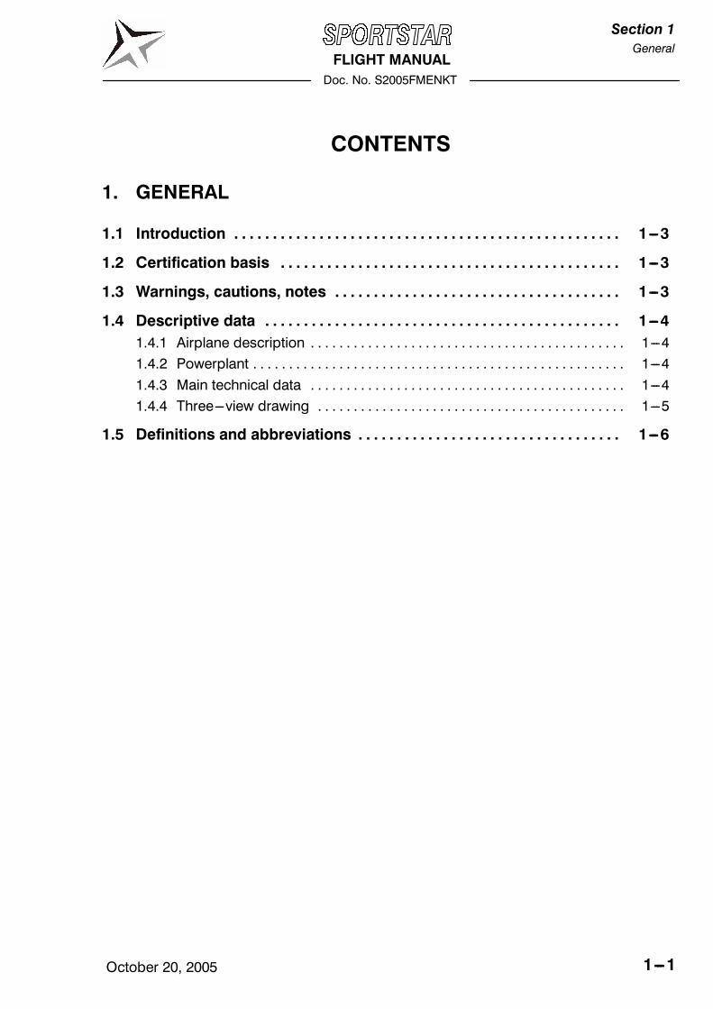
4.5.2 Engine starting
1. MASTER SWITCH ON. . . . . . . . . . . . . . . . . . . . . . . .
2. Fuel gauge indicators check of fuel quantity. . . . . . . . . . . . . . . . . . . . .
3. FUEL SELECTOR LEFT. . . . . . . . . . . . . . . . . . . . . . . .
Pull the safety button on the fuel selector, turn the handle to the left and then
release safety button. Now the handle can be freely moved between left and
right position. Safety button prevents unintentionally switch the selector to OFF
position.
4. Electric fuel pump (if installed) ON. . . . . . . . . . . . . . .
5. THROTTLE lever idle. . . . . . . . . . . . . . . . . . . . . . . . .
6. Choke as necessary. . . . . . . . . . . . . . . . . . . . . . . . . . . . . . . . . . .
(open by pulling
up and lock by turning)
7. Space in the propeller area free. . . . . . . . . . . . . . . .
8. BEACON (if installed) ON (if necessary). . . . . . . . . . . . . . . . . . . . .
9. Ignition START (see CAUTION) after. . . . . . . . . . . . . . . . . . . . . . . . . . . . . . . . . .
starting up BOTH
CAUTION
ACTIVATE STARTER FOR 10 SEC. AS A MAXIMUM,
THEN LET IT COOL DOWN FOR 2 MINUTES.
AFTERSTARTINGUP ENGINE,DONOT CARRYOUT
SUDDEN RPM CHANGES, AFTER POWER DE-
CREASEWAITFORABOUT3S INORDERTOREACH
CONSTANT RPM BEFORE REACCELERATION.
10. THROTTLE lever as necessary (see NOTE). . . . . . . . . . . . . . . . . . . . . . . . .
11. Oil pressure up to 10s min. pressure. . . . . . . . . . . . . . . . . . . . . . . . . . . . . .
12. Electric fuel pump (if installed) OFF. . . . . . . . . . . . . . .
NOTE
After starting up engine, adjust throttle for smooth en-
gine running at about 2500 RPM. Check oil pressure.
Pressure must increase within 10s. Increase engine
RPM until oil pressure is stabilised over 2 bar (29 PSI).
Electric fuel pump operates during engine starting pe-
riod only. It is not intended for long continuous opera-
tion for long time.

FLIGHT MANUAL
Doc. No. S2005FMENKT
Section 4
Normal
Procedures
October 20, 2005 4---9
13. Engine instruments check. . . . . . . . . . . . . . . . . . . . . . .
14. Choke as necessary. . . . . . . . . . . . . . . . . . . . . . . . . . . . . . . . . . .
15. Engine warming up see NOTE. . . . . . . . . . . . . . . . . . . . . . .
NOTE
Begin warming up with engine running at 2000 RPM.
for about 2 minutes, continue at 2500 RPM. Warming
time depends on outside air temperature until oil tem-
perature reaches 50˚C (122 ˚F).
16. FUEL SELECTOR RIGHT. . . . . . . . . . . . . . . . . . . . . . . .
Verify proper engine feeding from the right tank for approx. 1 minute.
17. FUEL SELECTOR LEFT. . . . . . . . . . . . . . . . . . . . . . . .
NOTE
Start engine with the fuel selector set to to LEFT. If you
would start the engine with the fuel selector set toRIGHT and the left tank is full, than fuel bleed from the
left tank vent may occur (and pollute environment) be-
cause a fuel return hose is led only into the left tank and
returning fuel will overfill the left tank.
18. Radiostation/avionics ON. . . . . . . . . . . . . . . . . . . . . .
19. Other electrical equipment ON as necessary. . . . . . . . . . . . . . . . .
4.5.3 Before taxiing
1. Transponder (if installed) SBY. . . . . . . . . . . . . . . . . .
2. Outside lights (if installed) as necessary. . . . . . . . . . . . . . . . .
4.5.4 Taxiing
1. THROTTLE lever as necessary. . . . . . . . . . . . . . . . . . . . . . . . .
2. Brakes check by depressing. . . . . . . . . . . . . . . . . . . . . . . . . . . . . . . . . .
3. Rudder pedals function check. . . . . . . . . . . . . . . . . . . . . . . . . . .
4. Direction of taxiing --- control by rudder pedals (these are mechanically con-
nected with nose wheel control), possibly by slacking up left and right wheel of
the main landing gear.
4.5.5 Before take---off
1. Brakes brake. . . . . . . . . . . . . . . . . . . . . . . . . . . . . . . . . .
2. Ignition check carry out, see NOTE. . . . . . . . . . . . . . . . . . . . . . . . . . . .

FLIGHT MANUAL
Doc. No. S2005FMENKT
Section 4
Normal
Procedures
October 20, 20054---10
NOTE
Carry out ignition check in the following way :
Set engine speed to 4000 RPM. Switch ignition gradu-
ally to L, BOTH, R position and return to BOTH..
RPM drop with one ignition circuit switched off must
not exceed 300 RPM. Maximum RPM difference at us-
ing one of the L or R circuits is 120 RPM.
3. Engine instruments check. . . . . . . . . . . . . . . . . . . . . . .
4. Control stick free. . . . . . . . . . . . . . . . . . . . . . . . . . . . .
5. Wing flaps take---off pos. (15˚). . . . . . . . . . . . . . . . . . . . . . . . . . . . . . .
6. Trim NEUTRAL. . . . . . . . . . . . . . . . . . . . . . . . . . . . . . . . . . . . .
7. Fuel gauge indicators check on fuel quantity. . . . . . . . . . . . . . . . . . . . .
8. FUEL SELECTOR check LEFT. . . . . . . . . . . . . . . . . . . . . . . .
9. CARBURETTOR PREHEATER (if installed) check function then OFF. .
NOTE
IfCARBURETTORPREHEATER is switchedON, then
engine RPM drop reaches approximately 50 RPM
10. Engine instruments check. . . . . . . . . . . . . . . . . . . . . . .
11. Flight instruments check. . . . . . . . . . . . . . . . . . . . . . . .
12. Radiostation / avionics check, set. . . . . . . . . . . . . . . . . . . .
13. Ignition check BOTH. . . . . . . . . . . . . . . . . . . . . . . . . . . . . . . . . .
14. Choke close (in inserted position). . . . . . . . . . . . . . . . . . . . . . . . . . . . . . . . . . .
15. MASTER SWITCH check ON. . . . . . . . . . . . . . . . . . . . . . . .
16. Safety harnesses tighten up. . . . . . . . . . . . . . . . . . . . . . . . .
17. Canopy closed. . . . . . . . . . . . . . . . . . . . . . . . . . . . . . . . . .
18. Transponder (if installed) ON or ALT. . . . . . . . . . . . . . . . . .

FLIGHT MANUAL
Doc. No. S2005FMENKT
Section 4
Normal
Procedures
October 20, 2005 4---11
4.5.6 Take---off
1. THROTTLE lever max. take---off power. . . . . . . . . . . . . . . . . . . . . . . . .
2. During take---off run smootly lighten up the nose landing gear until airplane
take---off occurs.
3. Airpeed 55 KIAS (63 mph IAS). . . . . . . . . . . . . . . . . . . . . . . . . . . . . . . . .
4. Brakes brake. . . . . . . . . . . . . . . . . . . . . . . . . . . . . . . . . .
5. After reaching 150 ft , set flaps to retracted pos. (0˚). . . . . . . . . .
6. Trim as necessary. . . . . . . . . . . . . . . . . . . . . . . . . . . . . . . . . . . . .
WARNING
TAKE---OFF IS PROHIBITED:
���� IF ENGINE RUNNING IS IRREGULAR
���� IF CHOKE IS OPEN
���� IF VALUES OF ENGINE INSTRUMENTS ARE NOT
WITHIN THE REQUIRED RANGE
4.5.7 Climb
1. THROTTLE lever max. continuous power. . . . . . . . . . . . . . . . . . . . . . . . .
2. Airspeed 62 KIAS (71 mph IAS). . . . . . . . . . . . . . . . . . . . . . . . . . . . . . . . .
3. Engine instruments check. . . . . . . . . . . . . . . . . . . . . . .
4. Trim as necessary. . . . . . . . . . . . . . . . . . . . . . . . . . . . . . . . . . . . .
4.5.8 Cruise
1. THROTTLE lever as necessary. . . . . . . . . . . . . . . . . . . . . . . . .
2. Airspeed 103 KIAS (118 mph IAS). . . . . . . . . . . . . . . . . . . . . . . . . . . . . . . . .
3. Engine instruments check. . . . . . . . . . . . . . . . . . . . . . .
4. Fuel quantity check. . . . . . . . . . . . . . . . . . . . . . . . . . . . .
CAUTION
FUEL GAUGES DISPLAY TRUE FUEL QUANTITY
ONLY ON GROUND AND IN A LEVEL FLIGHT. TOREAD TRUE FUEL QUANTITY AFTER TRANSITIONFROM CLIMB/DESCENT WAIT APPROX. 2 MINUTES
TO FUEL TO LEVEL.
5. FUEL SELECTOR as required. . . . . . . . . . . . . . . . . . . . . . . .

FLIGHT MANUAL
Doc. No. S2005FMENKT
Section 4
Normal
Procedures
October 20, 20054---12
NOTE
It is recommended to alternately switch the tanksduring cruise to equally consume fuel from both tanksand minimize airplane tendency to bank withunbalanced tanks.Do not fly with the fuel selector set to RIGHT if the lefttank is full to avoid fuel bleed from left tank vent.When the left tank fuel gauge indicates approx. 1/8 offuel quantity (needle in the middle between 1/4 and 0)then switch to the right tank to consume remaining fueland then switch back the left tank to complete the flightat left tank. If the engine conks out due to fuelconsumption from either tank, then immediatelyswitch the fuel selector to other tank and engine runwill be recovered within 7 seconds.
6. CARBURETTOR PREHEATER (if installed) as necessary. .
4.5.9 Descent
1. THROTTLE lever as necessary. . . . . . . . . . . . . . . . . . . . . . . . .
2. Trim as necessary. . . . . . . . . . . . . . . . . . . . . . . . . . . . . . . . . . . . .
3. Engine instruments check. . . . . . . . . . . . . . . . . . . . . . .
4. CARBURETTOR PREHEATER (if installed) as necessary. .
CAUTION
AT LONG APPROACHING AND DESCENDING FROM
HIGH ALTITUDE IT IS NOT SUITABLE TO REDUCE
THROTTLE TO MINIMUM FOR THE REASON OF POS-
SIBLE ENGINE UNDERCOOLING AND SUBSEQUENT
LOSS OF POWER. PERFORM DESCENDING AT IN-
CREASED IDLE AND CHECK OBSERVANCE OF THE
ALLOWED VALUES ON ENGINE INSTRUMENTS.
4.5.10Before landing
1. Fuel quantity check. . . . . . . . . . . . . . . . . . . . . . . . . . . . .
CAUTION
FUEL GAUGES DISPLAY TRUE FUEL QUANTITYONLY ON GROUND AND IN A LEVEL FLIGHT. TOREAD TRUE FUEL QUANTITY AFTER TRANSITION
FROM CLIMB/DESCENT WAIT APPROX. 2 MINUTESTO FUEL TO LEVEL.

FLIGHT MANUAL
Doc. No. S2005FMENKT
Section 4
Normal
Procedures
October 20, 2005 4---13
2. FUEL SELECTOR LEFT. . . . . . . . . . . . . . . . . . . . . . . .
3. Engine instruments check. . . . . . . . . . . . . . . . . . . . . . .
4. Brakes check by depressing pedals. . . . . . . . . . . . . . . . . . . . . . . . . . . . . . . . . .
5. Safety harnesses tighten up. . . . . . . . . . . . . . . . . . . . . . . . .
6. Free area of landing check. . . . . . . . . . . . . . . . . . . . . . .
7. CARBURETTOR PREHEATER (if installed) ON. .
8. Approaching speed 59 KIAS (68 mph IAS). . . . . . . . . . . . . . . . . . . . . . . .
9. Flaps take---off pos. (15˚). . . . . . . . . . . . . . . . . . . . . . . . . . . . . . . . . . . .
10. Trim as necessary. . . . . . . . . . . . . . . . . . . . . . . . . . . . . . . . . . . . .
FINAL
1. Flaps landing pos. (30˚ or 50˚). . . . . . . . . . . . . . . . . . . . . . . . . . . . . . . . . . . .
2. Maintain airspeed 48 KIAS (55 mph IAS). . . . . . . . . . . . . . . . . . . . . . . . . .
3. Trim as necessary. . . . . . . . . . . . . . . . . . . . . . . . . . . . . . . . . . . . .
4. CARBURETTOR PREHEATER (if installed) OFF. .
4.5.11Balked landing
1. THROTTLE lever max. take---off power. . . . . . . . . . . . . . . . . . . . . . . . .
2. Flaps take---off pos. (15˚ ). . . . . . . . . . . . . . . . . . . . . . . . . . . . . . . . . . . .
3. Airspeed 55 KIAS (63 mph IAS). . . . . . . . . . . . . . . . . . . . . . . . . . . . . . . . . .
4. Flaps in 150 ft retracted pos. (0˚). . . . . . . . . . . . . . . . . . . . . . . . . . . .
5. Trim as necessary. . . . . . . . . . . . . . . . . . . . . . . . . . . . . . . . . . . .
6. THROTTLE lever max. continuous power. . . . . . . . . . . . . . . . . . . . . . . . .
7. Instruments check. . . . . . . . . . . . . . . . . . . . . . . . . . . . . .
8. Climb at airspeed 62 KIAS (71 mph IAS). . . . . . . . . . . . . . . . . . . . . . . . .
4.5.12Landing
1. THROTTLE lever idle. . . . . . . . . . . . . . . . . . . . . . . . .
2. Touch---down on main landing gear wheels carry out. .
3. Brakes after nose landing gear
wheel touch---down as necessary. . . . . . . . . . . . . . . . . . . . . . .

FLIGHT MANUAL
Doc. No. S2005FMENKT
Section 4
Normal
Procedures
October 20, 20054---14
4.5.13After landing
1. Flaps retracted pos. (0˚). . . . . . . . . . . . . . . . . . . . . . . . . . . . . . . . . . . .
2. Trim NEUTRAL. . . . . . . . . . . . . . . . . . . . . . . . . . . . . . . . . . . . .
3. Outside lights (if installed) OFF. . . . . . . . . . . . . . . . .
4. Transponder (if installed) OFF. . . . . . . . . . . . . . . . . .
4.5.14Engine shut---off
1. THROTTLE lever idle. . . . . . . . . . . . . . . . . . . . . . . . .
2. Engine instruments check. . . . . . . . . . . . . . . . . . . . . . .
3. Radiostation / avionics OFF. . . . . . . . . . . . . . . . . . . .
4. Other electrical equipment OFF. . . . . . . . . . . . . . . . .
5. Ignition OFF. . . . . . . . . . . . . . . . . . . . . . . . . . . . . . . . . .
6. BEACON (if installed) OFF. . . . . . . . . . . . . . . . . . . . .
7. MASTER SWITCH OFF. . . . . . . . . . . . . . . . . . . . . . . .
4.5.15Airplane parking
1. Ignition check OFF. . . . . . . . . . . . . . . . . . . . . . . . . . . . . . . . . .
2. MASTER SWITCH check OFF. . . . . . . . . . . . . . . . . . . . . . . .
3. FUEL SELECTOR OFF. . . . . . . . . . . . . . . . . . . . . . . .
Pull the safety button on the fuel selector, turn the handle to the OFF position
and then release safety button. Now the handle is blocked in the OFF position.
Safety button prevents unintentionally switch the selector from the OFF posi-
tion.
4. PARKING BRAKE handle (if installed) brake as necessary. . . . . . .
5. Canopy close, lock as necessary. . . . . . . . . . . . . . . . . . . . . . . . . . . . . . . . . .
NOTE
It is recommended to use parking brake (if installed) forshort---time parking only, between flights during aflight day. After ending the flight day or at low tempera-
tures of ambient air, do not use parking brake, but usethe wheel chocks instead.

FLIGHT MANUALDoc. No. S2005FMENKT
Section 5Performance
October 20, 2005 5---1
CONTENTS
5. PERFORMANCE
5.1 Introduction 5---3. . . . . . . . . . . . . . . . . . . . . . . . . . . . . . . . . . . . . . . . . . . . . . . . . .
5.2 Approved data 5---4. . . . . . . . . . . . . . . . . . . . . . . . . . . . . . . . . . . . . . . . . . . . . . . .5.2.1 Airspeed indicator system calibration 5---4. . . . . . . . . . . . . . . . . . . . . . . . . . . . .5.2.2 Stall speeds 5---6. . . . . . . . . . . . . . . . . . . . . . . . . . . . . . . . . . . . . . . . . . . . . . . . . . .5.2.3 Take---off distance 5---7. . . . . . . . . . . . . . . . . . . . . . . . . . . . . . . . . . . . . . . . . . . . . .5.2.4 Landing distance 5---7. . . . . . . . . . . . . . . . . . . . . . . . . . . . . . . . . . . . . . . . . . . . . .5.2.5 Climb performance 5---8. . . . . . . . . . . . . . . . . . . . . . . . . . . . . . . . . . . . . . . . . . . .
5.3 Additional information 5---9. . . . . . . . . . . . . . . . . . . . . . . . . . . . . . . . . . . . . . . . .5.3.1 Cruise 5---9. . . . . . . . . . . . . . . . . . . . . . . . . . . . . . . . . . . . . . . . . . . . . . . . . . . . . . . .5.3.2 Horizontal speeds 5---10. . . . . . . . . . . . . . . . . . . . . . . . . . . . . . . . . . . . . . . . . . . . .5.3.3 Endurance 5---11. . . . . . . . . . . . . . . . . . . . . . . . . . . . . . . . . . . . . . . . . . . . . . . . . . . .5.3.4 Balked landing climb 5---12. . . . . . . . . . . . . . . . . . . . . . . . . . . . . . . . . . . . . . . . . . .5.3.5 Effect on flight performance and characteristics 5---13. . . . . . . . . . . . . . . . . . . .5.3.6 Demonstrated crosswind performance 5---13. . . . . . . . . . . . . . . . . . . . . . . . . . .5.3.7 Ceiling 5---14. . . . . . . . . . . . . . . . . . . . . . . . . . . . . . . . . . . . . . . . . . . . . . . . . . . . . . .5.3.8 Noise data 5---14. . . . . . . . . . . . . . . . . . . . . . . . . . . . . . . . . . . . . . . . . . . . . . . . . . . .

FLIGHT MANUALDoc. No. S2005FMENKT
Section 5Performance
October 20, 20055---2
Intentionally left blank

FLIGHT MANUALDoc. No. S2005FMENKT
Section 5Performance
October 20, 2005 5---3
5.1 IntroductionSection 5 provides data for airspeed calibration, stall speeds, take---off performanceand nonapproved additional information, provided by the airplane type certificateowner.
The stated performance data has been computed from actual flight tests with theSPORTSTAR airplane and ROTAX 912 S engine in good condition and usingaverage piloting techniques.
CAUTION
THE PERFORMANCE STATED IN THIS SECTION ISVALID FOR ROTAX 912 S (100 HP) TOGETHERWITHWOODCOMP KLASSIC 170/3/R PROPELLERINSTALLED IN THE AIRPLANE, OTHERWISE SEESECTION 9 --- SUPPLEMENTS FOR ACTUAL PER-FORMANCE.

FLIGHT MANUALDoc. No. S2005FMENKT
Section 5Performance
October 20, 20055---4
5.2 Approved data
5.2.1 Airspeed indicator system calibration
NOTEAssumed zero instrument error.Valid for airplane take---off weight 1213 lbs (550 kg) .
KIASkts CAS
KIASflaps 0˚ 15˚ 50˚
37 3940 42 4143 45 44 4445 47 46 4548 49 49 4850 51 50 4953 53 53 5255 55 54 5458 58 57 5761 60 60 6064 63 63 6367 66 66 6670 68 68 6975 7380 7785 8190 8695 90100 95105 99110 104115 109120 113125 118130 122135 127140 132146 137

FLIGHT MANUALDoc. No. S2005FMENKT
Section 5Performance
October 20, 2005 5---5
mph IASmph CAS
mph IASflaps 0˚ 15˚ 50˚
43 4546 48 4750 52 51 5055 57 56 5559 60 59 5965 65 64 6470 69 69 6976 74 74 7480 78 77 7785 8290 8795 91100 96105 100110 105115 109120 114125 118130 123135 127140 132145 137150 141155 146160 151168 158

FLIGHT MANUALDoc. No. S2005FMENKT
Section 5Performance
October 20, 20055---6
5.2.2 Stall speeds
Conditions: --- wing level stall --- engine at idle power--- turning flight stall --- engine at 75% max. continuous power--- airplane weight: 1213 lbs (550 kg)
NOTEThe stated stall speeds are valid for all flight altitudes.
Altitude losses shown in the table present max. valuesdetermined on the basis of flight tests using averagepiloting technique.
Flapsposition
Stall speed Altitudeloss
position KIAS KCAS ft
Wi l lRetracted (0˚) 42 44
Wing levelflight
Take---off (15˚) 40 42 200flightLanding (50˚) 37 39
Turn flight( di t d
Retracted (0˚) 46 48(coordinatedturn
Take---off (15˚) 43 45 200turn,30˚ bank) Landing (50˚) 40 41
Flapsposition
Stall speed Altitudeloss
position mph IAS mph CAS ft
Wi l lRetracted (0˚) 49 51
Wing levelflight
Take---off (15˚) 46 48 200flightLanding (50˚) 43 45
Turn flight( di t d
Retracted (0˚) 53 55(coordinatedturn
Take---off (15˚) 50 52 200turn,30˚ bank) Landing (50˚) 46 47

FLIGHT MANUALDoc. No. S2005FMENKT
Section 5Performance
October 20, 2005 5---7
5.2.3 Take---off distance
Conditions: --- engine: max. take---off power--- flaps: Take---off (15˚)--- carburetter preheating: OFF--- airplane weight: 1213 lbs (550 kg)--- Altitude: 0 ft ISA--- ambient air temperature: ISA
Take---off run Take---off distance toheight of 50 ft (15 ft)
Dray concrete 570 ft (174 m) 1310 ft (399 m)Grass 660 ft (200 m) 1395 ft (425 m)
Corrections: --- Influence of wind: Add 4% on every 1 kt (1.15 mph) of tail wind--- RWY inclination: Add 8% of the take---off run distance on 1% of ruway
inclination up the slope
5.2.4 Landing distance
Conditions: --- engine: idle--- flaps: Landing 50˚--- carburetter preheating: OFF--- airplane weight: 1213 lbs (550 kg)--- Altitude: 0 ft ISA--- ambient air temperature: ISA
Landing distancefrom height of50 ft (15 ft)
Braked landing run
Dray concrete 1185 ft (360 m) 545 ft (165 m)Grass 1125 ft (343 m) 485 ft (148 m)
Corrections: --- Influence of wind: Add 4.5 % on every 1 kt (1.15 mph) of tail wind--- RWY inclination: Add 8% of the landing run distance on 1% of
ruway inclination down the slope

FLIGHT MANUALDoc. No. S2005FMENKT
Section 5Performance
October 20, 20055---8
5.2.5 Climb performance
Conditions: --- engine: maximun take---off power--- flaps: retracted (0˚)--- carburetter preheating: OFF--- airplane weight: 1213 lbs (550 kg)--- ambient air temperature: ISA

FLIGHT MANUALDoc. No. S2005FMENKT
Section 5Performance
October 20, 2005 5---9
Best rate of climb for various altitudes is mentioned in the following table:

FLIGHT MANUALDoc. No. S2005FMENKT
Section 5Performance
October 20, 20055---10
5.3 Additional information
5.3.1 Cruise
Conditions: --- flaps: retracted (0˚)--- carburetter preheating: OFF--- airplane weight: 1213 lbs (550 kg)--- ambient air temperature: ISA

FLIGHT MANUALDoc. No. S2005FMENKT
Section 5Performance
October 20, 2005 5---11
5.3.2 Horizontal speeds
In the following table states Indicated airspeeds (IAS) and corresponding True airspeeds versus altitude, all for various engine speeds.

FLIGHT MANUALDoc. No. S2005FMENKT
Section 5Performance
October 20, 20055---12
5.3.3 Endurance
Conditions: --- flaps: retracted (0˚)--- carburetter preheating: OFF--- airplane weight: 1213 lbs (550 kg)--- ambient air temperature: ISA

FLIGHT MANUALDoc. No. S2005FMENKT
Section 5Performance
October 20, 2005 5---13
5.3.4 Balked landing climb
Conditions: --- engine: maximum take---off power--- carburetter preheating: OFF--- flaps: landing position (50˚)--- airplane weight: 1213 lbs (550 kg)--- ambient air temperature: ISA

FLIGHT MANUALDoc. No. S2005FMENKT
Section 5Performance
October 20, 20055---14
5.3.5 Effect on flight performance and characteristics
Flight performances and characteristics are not considerably affected by rain or in-sect stuck on the airplane surface.
5.3.6 Demonstrated crosswind performance
Maximum demonstrated speed of windat airplane operation 24 kts (28 mph). . . . . . . . . . . . . . . . . . . . . . . . .
Maximum demonstrated speed of cross windfor take---off and landing 10 kts (12 mph). . . . . . . . . . . . . . . . . . . . . .
Maximum demonstrated speed of tail wind 6 kts (7 mph). . . . .
Figure 5-1 Influence of wind on take---off and landing
FLIGHT MANUALDoc. No. S2005FMENKT
Section 5Performance
October 20, 2005 5---15
5.3.7 Ceiling
Service ceiling of SPORTSTAR 13 800 ft. . . . . . . . . . . . . . . .
5.3.8 Noise data
Not measured.

FLIGHT MANUAL
Doc. No. S2005FMENKT
Section 6
Weight &Balance
October 20, 2005 6---1
CONTENTS
6. WEIGHT AND BALANCE
6.1 Introduction 6---3. . . . . . . . . . . . . . . . . . . . . . . . . . . . . . . . . . . . . . . . . . . . . . . . . .
6.2 Weight and balance record 6---5. . . . . . . . . . . . . . . . . . . . . . . . . . . . . . . . . . . .
6.3 Permitted payload range 6---7. . . . . . . . . . . . . . . . . . . . . . . . . . . . . . . . . . . . . . .

FLIGHT MANUAL
Doc. No. S2005FMENKT
Section 6
Weight &Balance
October 20, 20056---2
Intentionally left blank

FLIGHT MANUAL
Doc. No. S2005FMENKT
Section 6
Weight &Balance
October 20, 2005 6---3
6.1 Introduction
This section includes airplane weighing procedure a determination of its centre of
gravity position, further then determination of allowed loading range at which
SPORTSTAR airplane can be safely operated.
Proceduresfor weighing the airplane and the calculation method for establishing
the permitted payload range are contained in the Maintenance manual for the
SPORTSTAR airplane.

FLIGHT MANUAL
Doc. No. S2005FMENKT
Section 6
Weight &Balance
October 20, 20056---4
Intentionally left blank

FLIGHT MANUALDoc. No. S2005FMENKT
Section 6Weight andbalance
October 20, 2005 6---5
Type:SPORTSTAR
SerialNo.:
ItemNo.
Weightchange
Basicweightof
emptyairplane
Date
ItemNo.
Descriptionofpartormodification
Added(+)
Remove(---)
Basicweightof
emptyairplane
Date
+---
DescriptionofpartormodificationWeight.
[kg]
Arm[mm]Moment
[kg.mm]Weight
[kg]
Arm[mm]Moment
[kg.mm]Weight
[kg]
Moment
[kg.mm]
Manufacturedairplane
6.2 Weight and balance record

FLIGHT MANUALDoc. No. S2005FMENKT
Section 6Weight andbalance
October 20, 20056---6
Type:SPORTSTAR
SerialNo.:
ItemNo.
Weightchange
Basicweightof
Date
ItemNo.
Descriptionofpartormodification
Added(+)
Remove(---)
Basicweightof
emptyairplane
Date
+---
DescriptionofpartormodificationWeight.
[lb]
Arm [in]
Moment
[lb.in]Weight
[lb]
Arm [in]
Moment
[lb.in]Weight
[lb]
Moment
[lb.in]
Manufacturedairplane

FLIGHT MANUALDoc. No. S2005FMENKT
Section 6Weight andbalance
October 20, 2005 6---7
Maximumweightofcrew[kg]
Fueltanking
Approvedby
Date
Empty
weight
C.G.Fuelquantity
10.8
0.6
0.4
0.2
Date
Empty
weight
[kg]
C.G.
[%MAC]Fuelvolume
[litres]
120
100
7550
25Date
Signature
Fuelweight[kg]
8672
5436
18
25kg
12kg
0kg
B25kg
B A G15kg
G G0kg
G A25kg
A G E15kg
E0kg
25kg
15kg
0kg
6.3 Permitted payload range

FLIGHT MANUALDoc. No. S2005FMENKT
Section 6Weight andbalance
October 20, 20056---8
Maximumweightofcrew[lbs]
Fueltanking
Approvedby
Date
Empty
weight
C.G.Fuelquantity
10.8
0.6
0.4
0.2
Date
Empty
weight
[lbs]
C.G.
[%MAC]Fuelvolume
[U.S.gallons]
31.7
26.4
19.8
13.2
4.8
Date
Signature
Fuelweight[lbs]
190
159
119
7940
55lbs
26lbs
0lbs
B55lbs
B A26lbs
A G G0lbs
G A55lbs
A G E26lbs
E0lbs
55lbs
26lbs
0lbs
FLIGHT MANUALDoc. No. S2005FMENKT
Section 7Airplane and System
Description
October 20, 2005 7---1
CONTENTS
7. AIRPLANE AND SYSTEM DESCRIPTION
7.1 Introduction 7---3. . . . . . . . . . . . . . . . . . . . . . . . . . . . . . . . . . . . . . . . . . . . . . . . . .
7.2 Airframe 7---3. . . . . . . . . . . . . . . . . . . . . . . . . . . . . . . . . . . . . . . . . . . . . . . . . . . . . .7.2.1 Fuselage 7---3. . . . . . . . . . . . . . . . . . . . . . . . . . . . . . . . . . . . . . . . . . . . . . . . . . . . .7.2.2 Wing 7---3. . . . . . . . . . . . . . . . . . . . . . . . . . . . . . . . . . . . . . . . . . . . . . . . . . . . . . . . .7.2.3 Horizontal tail unit (HTU) 7---3. . . . . . . . . . . . . . . . . . . . . . . . . . . . . . . . . . . . . . . .7.2.4 Vertical tail unit (VTU) 7---3. . . . . . . . . . . . . . . . . . . . . . . . . . . . . . . . . . . . . . . . . . .
7.3 Control 7---4. . . . . . . . . . . . . . . . . . . . . . . . . . . . . . . . . . . . . . . . . . . . . . . . . . . . . . .7.3.1 Longitudinal control 7---4. . . . . . . . . . . . . . . . . . . . . . . . . . . . . . . . . . . . . . . . . . . .7.3.2 Lateral control 7---4. . . . . . . . . . . . . . . . . . . . . . . . . . . . . . . . . . . . . . . . . . . . . . . . .7.3.3 Rudder control 7---4. . . . . . . . . . . . . . . . . . . . . . . . . . . . . . . . . . . . . . . . . . . . . . . .7.3.4 Elevator trim tab control 7---4. . . . . . . . . . . . . . . . . . . . . . . . . . . . . . . . . . . . . . . .
7.4 Controls in cockpit 7---5. . . . . . . . . . . . . . . . . . . . . . . . . . . . . . . . . . . . . . . . . . . .
7.5 Instrument panel 7---6. . . . . . . . . . . . . . . . . . . . . . . . . . . . . . . . . . . . . . . . . . . . . .
7.6 Inside and outside marking and placards 7---6. . . . . . . . . . . . . . . . . . . . . . .
7.7 Landing gear and brakes 7---6. . . . . . . . . . . . . . . . . . . . . . . . . . . . . . . . . . . . . .7.7.1 Landing gear 7---6. . . . . . . . . . . . . . . . . . . . . . . . . . . . . . . . . . . . . . . . . . . . . . . . . .7.7.2 Brakes 7---6. . . . . . . . . . . . . . . . . . . . . . . . . . . . . . . . . . . . . . . . . . . . . . . . . . . . . . .
7.8 Seat and safety harnesses 7---6. . . . . . . . . . . . . . . . . . . . . . . . . . . . . . . . . . . . .
7.9 Baggage compartment 7---6. . . . . . . . . . . . . . . . . . . . . . . . . . . . . . . . . . . . . . . .
7.10 Canopy 7---7. . . . . . . . . . . . . . . . . . . . . . . . . . . . . . . . . . . . . . . . . . . . . . . . . . . . . .
7.11 Power unit 7---7. . . . . . . . . . . . . . . . . . . . . . . . . . . . . . . . . . . . . . . . . . . . . . . . . . . .7.11.1General 7---7. . . . . . . . . . . . . . . . . . . . . . . . . . . . . . . . . . . . . . . . . . . . . . . . . . . . . . .7.11.2Engine control 7---7. . . . . . . . . . . . . . . . . . . . . . . . . . . . . . . . . . . . . . . . . . . . . . . . .7.11.3Engine intruments 7---7. . . . . . . . . . . . . . . . . . . . . . . . . . . . . . . . . . . . . . . . . . . . .7.11.4Engine cooling system 7---8. . . . . . . . . . . . . . . . . . . . . . . . . . . . . . . . . . . . . . . . .7.11.5Engine lubrication system 7---9. . . . . . . . . . . . . . . . . . . . . . . . . . . . . . . . . . . . . . .7.11.6Engine intake system 7---9. . . . . . . . . . . . . . . . . . . . . . . . . . . . . . . . . . . . . . . . . . .7.11.7 Ignition system 7---9. . . . . . . . . . . . . . . . . . . . . . . . . . . . . . . . . . . . . . . . . . . . . . . .

FLIGHT MANUALDoc. No. S2005FMENKT
Section 7Airplane and SystemDescription
October 20, 20057---2
7.12 Fuel system 7---10. . . . . . . . . . . . . . . . . . . . . . . . . . . . . . . . . . . . . . . . . . . . . . . . . .7.12.1Fuel tank 7---10. . . . . . . . . . . . . . . . . . . . . . . . . . . . . . . . . . . . . . . . . . . . . . . . . . . . .7.12.2Fuel selector 7---10. . . . . . . . . . . . . . . . . . . . . . . . . . . . . . . . . . . . . . . . . . . . . . . . . .7.12.3Fuel filter 7---10. . . . . . . . . . . . . . . . . . . . . . . . . . . . . . . . . . . . . . . . . . . . . . . . . . . . . .7.12.4 Indication of fuel quantity 7---10. . . . . . . . . . . . . . . . . . . . . . . . . . . . . . . . . . . . . . .7.12.5Fuel tank draining 7---10. . . . . . . . . . . . . . . . . . . . . . . . . . . . . . . . . . . . . . . . . . . . . .
7.13 Electrical system 7---12. . . . . . . . . . . . . . . . . . . . . . . . . . . . . . . . . . . . . . . . . . . . .7.13.1Lightning 7---12. . . . . . . . . . . . . . . . . . . . . . . . . . . . . . . . . . . . . . . . . . . . . . . . . . . . .7.13.2Electrical system scheme 7---12. . . . . . . . . . . . . . . . . . . . . . . . . . . . . . . . . . . . . . .
7.14 Pitot---static system 7---14. . . . . . . . . . . . . . . . . . . . . . . . . . . . . . . . . . . . . . . . . . .
7.15 Supplementary equipment 7---15. . . . . . . . . . . . . . . . . . . . . . . . . . . . . . . . . . . . .7.15.1Ventilation and heating system 7---15. . . . . . . . . . . . . . . . . . . . . . . . . . . . . . . . . .
7.16 Navigation and communication equipment 7---15. . . . . . . . . . . . . . . . . . . . . .

FLIGHT MANUALDoc. No. S2005FMENKT
Section 7Airplane and System
Description
October 20, 2005 7---3
7.1 IntroductionThis section describes systems of the airplane and its operation.More detailed information on optional systems and equipment are available in sec-tion 9, Supplements.
7.2 AirframeThe airframe of SPORTSTAR airplane is of semimonocoque structure consisting ofmetal reinforcement, frames and duralumin sheet skin.
7.2.1 Fuselage
The fuselage is of semimonocoque structure consisting of reinforcements and du-ralumin skin. Fuselage section is rectangular in the lower part and eliptic in the up-per part. The fin is an integral part of fuselage. The cockpit for two---member crew islocated in the middle part of the fuselage that is accessible after uncovering thesingle---piece organic glass canopy. The engine compartment in the front part ofthe fuselage is separated from the cockpit by the steel fire wall to which the enginebed is attached.
7.2.2 Wing
The wing is of rectangular shape, single---spar structure with the auxiliary spar withsuspended ailerons and split wing flaps. Riveting is used for connecting individual-structural elements. Fiber---glass wing tips are riveted on the wing eds.
7.2.3 Horizontal tail unit (HTU)
The VTU of conventional type consists of the stabilizer and elevator with the trimtab. Single---spar structure of HTU consists of duralumin ribs, spar and skin. Topview of HTU is of rectangular shape.
7.2.4 Vertical tail unit (VTU)
VTU is of trapezoidal shape. Its fin is an integral part of the fuselage. The rudder issuspended on the fin by means of two hinges. The VTU structure consists of theduralumin spar and skin.

FLIGHT MANUALDoc. No. S2005FMENKT
Section 7Airplane and SystemDescription
October 20, 20057---4
7.3 ControlAirplane control consists of ailerons, elevator and rudder. Directional control isconnected by means of pull rods with nose landing gear control. Main landing gearbrakes are controlled by pedals of directional control.Airplane is equipped with coupled control enabling flight with two---member crew.
7.3.1 Longitudinal control
Longitudinal control is actuated by the control stick. Longitudinal movement of con-trol stick is transferred to the elevator by mechanical system of pull rods and levers.
7.3.2 Lateral control
Lateral control is actuated by the control stick. From the control stick the movementis transferred through the system of levers and pull rods to ailerons.
7.3.3 Rudder control
Rudder control is controlled by pedals of foot control. The rudder is interconnectedwith foot control pedals by cable system.
Foot control pedals adjustable into three positions can be installed as an option.
Way of adjustment of ruder pedals:
1. Release the pin from the adjusting groove
2. Set pedal to one of three possible positions
3. Check on the pin locking---on in the adjusting groove
WARNING
RIGHT AND LEFT PEDAL OF RUDDER CONTROLMUST BE ADJUSTED IN THE SAME POSITIONSAND SECURED!
7.3.4 Elevator trim tab control
The elevator trim tab is controled by the lever located in between the pilot seats.The control lever is interconnected with the trim tab by means of cables and pul-leys.

FLIGHT MANUALDoc. No. S2005FMENKT
Section 7Airplane and System
Description
October 20, 2005 7---5
7.4 Controls in cockpit
1 Control stick2 Instrument panel3 Carburetter pre---heating knob(if installed)4 Cockpit heating / canopy defogselector (if installed)5 Hot air supply knob (if installed)6 Throttle lever7 Ignition
8 Choke9 Master switch10 Fuel selector11 Rudder control pedals12 Emergency parachutesystem lever (if installed)
13 Flap control lever14 Trim control lever15 Headset sockets
Figure 7-1 Cockpit control elements

FLIGHT MANUALDoc. No. S2005FMENKT
Section 7Airplane and SystemDescription
October 20, 20057---6
7.5 Instrument panelSee section 9 --- Supplements.
7.6 Inside and outside marking and placardsSee Maintenance Manual.
7.7 Landing gear and brakes
7.7.1 Landing gear
The airplane is equipped with a sort of fixed nose landing gear. Main landing gearlegs are produced from composite spring. Nose landing gear leg is welded fromtwo pieces --- the tube and the yoke--- in which the nose wheel is mounted. Thenose landing gear is spring--- loaded by a rubber rope. The nose wheeel is control-lable, wheel control is coupled with rudder control by means of two pull rods.Wheels can be fitted with fiber---glass aerodynamic covers.
7.7.2 Brakes
The SPORTSTAR airplane is equipped with disk hydraulic brakes on main landinggear wheels. Brake system is composed of brake pedals (these are a part of ruddercontrol pedals), brake pumps, hoses for leading brake liquid, brake yokes withwheel cylinders and brake pads. By depressing the brake pedals compression ofbrake pumps occurs, which generates pressure in brake circuit and hydraulic cyl-inders press the brake pads onto the brake disks. Braking pressure can be regu-lated only by force of brake pedals depressing.
The airplane can be equipped by mechanical manually controlled parking brake.PARKING BRAKE handle is located in between the pilot seats.
7.8 Seat and safety harnessesSPORTSTAR is a two---seat airplane with side---by---side seats. Seats are fixed,non---adjustable and fitted with light upholstery.
Each of seats is fitted with four---point safety harness which is composed of safetybelts, shoulder straps and lock. The safety harness is anchored in the middle of theframe behind the baggage compartment and on the seat sides .
7.9 Baggage compartmentBaggage compartment is positioned behind seat rests.Maximum weight of baggage is 55 lbs (25 kg) and is stated on the placard in thebaggage compartment. The baggage compartment is fitted with rubber straps forbaggage fixation.

FLIGHT MANUALDoc. No. S2005FMENKT
Section 7Airplane and System
Description
October 20, 2005 7---7
7.10 Canopy
The cocpit canopy is of a semidrop shape. The framework is composed of metalstructure on which the organic glass canopy is fixed by bolts.
The canopy is attached to the fuselage in the front part by two swivel pins bymeans of which it can be folded up forwards. In order to make opening easier, theactual weight of canopy is balanced by two gas struts, besides the canopy is pro-vided with holders on the lower framework for easier handling. The canopy is pro-vided with the lock in the rear upper part of framework for locking.
7.11 Power unit
7.11.1General
The engine ROTAX 912 ULS. is used to power SPORTSTAR airplane as a stan-dard. ROTAX 912 ULS is a four---cylinder, four---stroke engine with opposite cylin-ders, central cam shaft and OHV valve mechanism with maximum power of 100 hp(73.5 kW) at 5800 RPM.
The on---groun adjustable, composite, 3---blade propeller WOODCOMP KLASSIC170/3/R. is standardly mounted on the engine ROTAX 912 ULS Other propellertype can be installed on customer�s request --- see section 9 for detailed informa-tion.
7.11.2Engine control
Engine power is controlled by means of THROTTLE lever, which is located in themiddle of the instrument panel and which controls engine power range from idle upto maximum take---off . Engine power controller is mechanically interconnectedwith the flap on carburetters.
If the lever is fully pushed in, then this position corresponds to maximum enginepower. If the lever is fully pulled out, then this position corresponds to idle. Rapidchanges in engine power setting can be made by pressing down the round buttonon the lever body and by its pulling out or pushing in. Small changes in power set-ting can be performed through lever turning (conterclockwise --- power increase).
The lever is fitted with the locking ring, counterclockwise turning of which ensureslocking of the lever in requested position.
7.11.3Engine intruments
The following analog instruments located on the instrument panel serve for engineperformance monitoring. The digital engine monitoring system can be installed inthe airplane instead of analog engine instruments.

FLIGHT MANUALDoc. No. S2005FMENKT
Section 7Airplane and SystemDescription
October 20, 20057---8
RPM indicator
The electrical RPM indicator is controlled by signal from the generator RPM trans-mitter. Working range of the RPM indicator is 0 --- 7000 RPM.. Colour code isstated in section 2, page 2---5.
Cylinder head thermometer
The cylinder head thermometer transmitter senses temperature of cylinder No. 3.Working range of the cylinder head thermometer is 50 150 ˚C (120 300˚F).Colour code is stated in section 2, page 2---5.
Oil thermometer
Oil temperature on engine input is measured by the sensor located behind the oilpump. Working range of oil thermometer is 50 150 ˚C. (120 300˚F). Colourcode is stated in section 2, page 2---5.
Oil pressure gauge
Oil pressure on the oil input into engine is measured by means of sensor which islocated behing the oil filter. Working range is 0 --- 10 bar. (0 150 PSI). Colour codeis stated in section 2, page 2---5.
7.11.4Engine cooling system
Engine cooling is combined, cylinder heads are cooled by water, cylinders arecooled by air.
Cooling circuit of cylinder heads is designed as a closed system containing pump, ex-pansion reservoir (1) with pressure closure (3), cooler of cooling liquid (2) and drainagereservoir (4). Scheme of cylinder head cooling system is shown in Fig. 7-2.
When changing, the cooling liquid is filled up through the cap of expansion reser-voir (1), during airplane operation it is replenished into drainage reservoir (4) be-tween the lines of maximum and minimum level.
Figure 7-2 Scheme of cylinder head cooling system
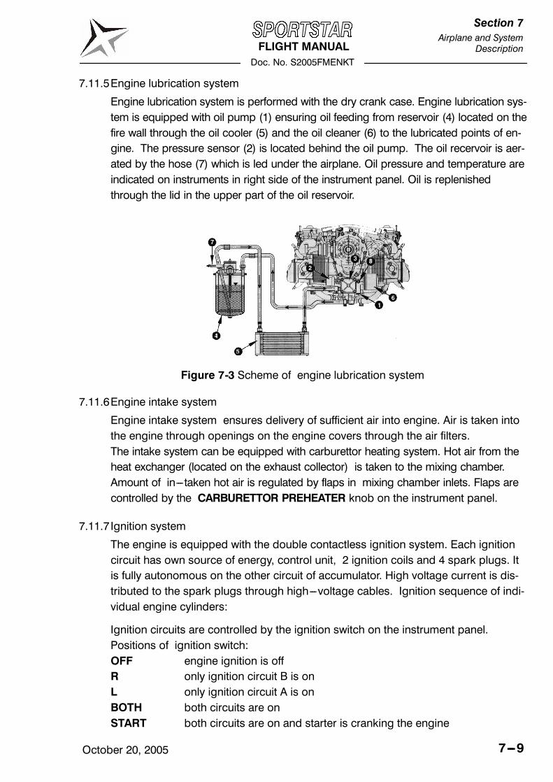
FLIGHT MANUALDoc. No. S2005FMENKT
Section 7Airplane and System
Description
October 20, 2005 7---9
7.11.5Engine lubrication system
Engine lubrication system is performed with the dry crank case. Engine lubrication sys-tem is equipped with oil pump (1) ensuring oil feeding from reservoir (4) located on thefire wall through the oil cooler (5) and the oil cleaner (6) to the lubricated points of en-gine. The pressure sensor (2) is located behind the oil pump. The oil recervoir is aer-ated by the hose (7) which is led under the airplane. Oil pressure and temperature areindicated on instruments in right side of the instrument panel. Oil is replenishedthrough the lid in the upper part of the oil reservoir.
Figure 7-3 Scheme of engine lubrication system
7.11.6Engine intake system
Engine intake system ensures delivery of sufficient air into engine. Air is taken intothe engine through openings on the engine covers through the air filters.The intake system can be equipped with carburettor heating system. Hot air from theheat exchanger (located on the exhaust collector) is taken to the mixing chamber.Amount of in---taken hot air is regulated by flaps in mixing chamber inlets. Flaps arecontrolled by the CARBURETTOR PREHEATER knob on the instrument panel.
7.11.7 Ignition system
The engine is equipped with the double contactless ignition system. Each ignitioncircuit has own source of energy, control unit, 2 ignition coils and 4 spark plugs. Itis fully autonomous on the other circuit of accumulator. High voltage current is dis-tributed to the spark plugs through high---voltage cables. Ignition sequence of indi-vidual engine cylinders:
Ignition circuits are controlled by the ignition switch on the instrument panel.Positions of ignition switch:OFF engine ignition is offR only ignition circuit B is onL only ignition circuit A is onBOTH both circuits are onSTART both circuits are on and starter is cranking the engine

FLIGHT MANUALDoc. No. S2005FMENKT
Section 7Airplane and SystemDescription
October 20, 20057---10
7.12 Fuel systemFuel system serves for keeping fuel in the airplane and its feeding to the engine.Fuel system of SPORTSTAR airplane is composed of integral fuel tanks, fuel line, fuelselector, fuel filter, mechanical fuel pump --- located on the engine (auxiliary electricalfuel pump can be installed), distribution pipe of fuel with, return branch of fuel, fuelgauges and fuel tanks draining valves.
7.12.1Fuel tanks
Fuel is contained in the wing integral tanks having volume 60 l (15.85 U.S. gallons)each. Each tank is fitted with air venting (output is under the wing tip) and drainingvalve on the bottom side of the wing. Fuel is led from the tanks through the hosesto the fuel selector located on a central console under the instrument panel andthen through a fuel filter to the engine pump and carburetors. Fuel return hosegoes from the fuel pump into the left tank, which is due to considered as a �prima-ry� tank. See figure 7---4 Scheme of fuel system.
7.12.2Fuel selector
The fuel selector serves for tank selection and fuel delivery interruption in case ofengine fire or long parking of airplane.To move selector from OFF (closed) position it necessary pull the safety button onthe fuel selector, turn the handle from the OFF position to the left and then releasesafety button. Now the handle can be freely moved between LEFT and RIGHT posi-tion. Safety button prevents unintentionally switch the selector to OFF position.To move selector to OFF (closed) position it is necessary pull the safety button onthe fuel selector, turn the handle to the OFF position and then release safety button.Now the handle is blocked in the OFF position. Safety button prevents unintention-ally switch the selector from the OFF position during parking.

FLIGHT MANUALDoc. No. S2005FMENKT
Section 7Airplane and System
Description
October 20, 2005 7---11
7.12.3Fuel filter
The fuel filter separates all mechanical impurities from fuel. The fuel filter is locatedin the cockpit on the left airframe panel.
7.12.4 Indication of fuel quantity
Fuel quantity is measured by a float fuel gauge transmitter in each tank and indi-cated on fuel gauge on the instrument panel. LH fuel gauges indicates fuel quantityin the left (primary) tank, RH indicator in the right tank. True fuel quantity is indi-cated only on ground and in level flight and it takes approx. 2 minutes to level fuelafter transition from climb/descent.
7.12.5Fuel tank draining
Draining of the fuel tank is specified in chapter 8.5 in page 8---6.

FLIGHT MANUALDoc. No. S2005FMENKT
Section 7Airplane and SystemDescription
October 20, 20057---12
Figure 7-4 Scheme of fuel system
FLIGHT MANUALDoc. No. S2005FMENKT
Section 7Airplane and System
Description
October 20, 2005 7---13
7.13 Electrical systemThe airplane is equipped with 14 V DC electrical installation. A generator withpower of 250 W is the primary source of electrical energy. The secondary source ofenergy is the accumulator 12V/16Ah that is located in the engine compartment onthe fire wall. It is used for engine starting and in case of generator failure as anemergency source of energy and also serves as the smoothing filter of powersystem.
DC voltage is distributed to individual systems by main busbar. Each system is pro-tected by fuse or circuit breakers. If overloading of any of the circuits occurs, thenthe fuse is broken or circuit breaker is pulled out. The fuses or circuit beakers arelisted in the Maintenance Manual.
After switching MASTER SWITCH on and by turning the ignition key to STARTposition the starter is activated. The starter is power supplied from the accumulatorbefore engine start. After engine has been started and idle RPM reached, generatorstarts supplying current into electrical network.
7.13.1Lightning
Airplane can be equipeed with a external lighting.
External lighting can be composed of position lights and anticollision beaconswhich are located in wing tip and landing headlight which is located in left wingleading edge or in the lower engine cowling. Position lights are switched by POS.LIGHTS switch and anticollision beacon by BEACON switch. Landing headlight isswitched by LDG LIGHT (or REFLECTOR) switch.
7.13.2Electrical system scheme
See Maintenance Manual.

FLIGHT MANUALDoc. No. S2005FMENKT
Section 7Airplane and SystemDescription
October 20, 20057---14
7.14 Pitot---static systemPitot---static tube for sensing static and total pressure is located under the left halfof the wing. Total pressure is sensed through the opening in the Pitot---static tubeface. Static pressure is sensed through openings on the tube circumference. Sys-tem of pressure distribution to individual instruments are made by means of flexibleplastic hoses. Transparent draining reservoirs are located in the pressure branch ofstatic and total pressure on the left fuselage side by the wing leading edge.
Static pressure is led to altimeter, airspeed indicator, variometer and altitude encoder (ifinstalled). Total pressure is led only to the airspeed indicator.
km/h ft
m/s
Static pressureTotal pressure
Condensate reservoir
Pitotstatic tube
Pilot cockpitWing
(if installed)
Figure 7-5 Scheme of pitot---static system

FLIGHT MANUALDoc. No. S2005FMENKT
Section 7Airplane and System
Description
October 20, 2005 7---15
7.15 Supplementary equipment
7.15.1Ventilation and heating system
Cockpit ventilation is ensured by two sliding windows located on the tilting canopy.
Cocpit heating is ensured by hot air from the heat exchanger. The heat exchangeris located on the exchaust pipe collector. Air from outside atmosphere is warmedup in the exhaust pipe collector and delivered through air hoses into the cockpit.Hot air quantity is regulated by the flap which is controlled by the HOT AIR knobon the instrument panel. The cockpit heating system can be equipped with a wind-shield blowing system.
7.16 Navigation and communication equipmentDescription of operation of navigation and communication equipment see section9 --- Supplements.
FLIGHT MANUALDoc. No. S2005FMENKT
Section 7Airplane and SystemDescription
October 20, 20057---16
Intentionally left blank

FLIGHT MANUAL
Doc. No. S2005FMENKT
Section 8
Airplane Handling,Servicing and Maintenance
October 20, 2005 8---1
CONTENTS
8. AIRPLANE HANDLING, SERVICING AND MAINTENANCE
8.1 Introduction 8---3. . . . . . . . . . . . . . . . . . . . . . . . . . . . . . . . . . . . . . . . . . . . . . . . . .
8.2 Airplane inspection period 8---3. . . . . . . . . . . . . . . . . . . . . . . . . . . . . . . . . . . . .
8.3 Modifications or airplane repairs 8---4. . . . . . . . . . . . . . . . . . . . . . . . . . . . . . .
8.4 Road transport 8---4. . . . . . . . . . . . . . . . . . . . . . . . . . . . . . . . . . . . . . . . . . . . . . . .
8.4.1 Airplane towing 8---4. . . . . . . . . . . . . . . . . . . . . . . . . . . . . . . . . . . . . . . . . . . . . . . .
8.4.2 Airplane parking 8---5. . . . . . . . . . . . . . . . . . . . . . . . . . . . . . . . . . . . . . . . . . . . . . .
8.4.3 Airplane anchoring 8---5. . . . . . . . . . . . . . . . . . . . . . . . . . . . . . . . . . . . . . . . . . . . .
8.4.4 Airplane jacking 8---6. . . . . . . . . . . . . . . . . . . . . . . . . . . . . . . . . . . . . . . . . . . . . . .
8.4.5 Levelling 8---6. . . . . . . . . . . . . . . . . . . . . . . . . . . . . . . . . . . . . . . . . . . . . . . . . . . . . .
8.4.6 Road transport 8---6. . . . . . . . . . . . . . . . . . . . . . . . . . . . . . . . . . . . . . . . . . . . . . . .
8.5 Draining of fuel tanks 8---6. . . . . . . . . . . . . . . . . . . . . . . . . . . . . . . . . . . . . . . . .
8.6 Cleaning and care 8---7. . . . . . . . . . . . . . . . . . . . . . . . . . . . . . . . . . . . . . . . . . . .

FLIGHT MANUAL
Doc. No. S2005FMENKT
Section 8
Airplane Handling,Servicing and Maintenance
October 20, 20058---2
Intentionally left blank

FLIGHT MANUAL
Doc. No. S2005FMENKT
Section 8
Airplane Handling,Servicing and Maintenance
October 20, 2005 8---3
8.1 Introduction
This section includes the procedures for airplaine handling, maintenance and
operation recommended by the manufacturer.
It is necessary to follow the set---down lubrication plan, scope and periodocity of
preventive maintenance depending on climatic and flight conditions according to
the Maintenance manual of SPORTSTAR.
Airplane owner should be in a permanent touch with the manufacturer, either direct-
ly or through the network of business representatives, which enables him to get the
newest information concerning airplane operation, handling and maintenance. The
manufacturer distributes this information to users through Service bulletins (Manda-
tory bulletins), Information bulletins (letters) and further instructions.
Mandatory bulletins are especially important for keeping up airworthiness and the
manufacturer considers them mandatory although they do not come into effect
before Airworthiness Directive is issued by aviation authority of user‘s country.
All correspondence with the airplane manufacturer, distributor or service center
must contain the airplane serial number. The airplane serial number is shown on
the title sheet of this Manual and on the production plate behind the rest of pilot
seats.
The manufacturer delivers along with airplane SPORTSTAR the“ Flight manual“
and the “ Maintenance Manual”.
8.2 Airplane inspection period
Periodical inspections and reviews of airplane must be carried out at the latest in
the following intervals:
--- after first 25 hours of operation
--- after every 50 hours of operation
--- after every 100+ 5 hours of operation
--- annual inspection
Details on periodical inspections are provided in the Maintenance Manual of
SPORTSTAR.

FLIGHT MANUAL
Doc. No. S2005FMENKT
Section 8
Airplane Handling,Servicing and Maintenance
October 20, 20058---4
8.3 Modifications or airplane repairs
All airplane repairs and modifications of airplane must be carried out by qualified
personnel in an approved service center.
Before implementation of airplane repairs contact the Civil aviation authority of the
country in which the airplane is registered, which evaluates influence of modifica-
tion on flight airworthiness.
Basic repairs of airplane are described in the Maintenance Manual of SPORTSTAR.
8.4 Road transport
8.4.1 Airplane towing
It is possible to move the airplane on a short distance by holding the fuselage end
in the position before the fin, enventually by holding the root part of wings.
The hand towing bar can be used for airplane relocation which will be fastened to
the nose wheel axis.
To turn the airplane on the spot, push on the fuselage end part in the area before
the fin, lift the nose wheel and turn the airplane in required direction.
WARNING
SWITCH OFF IGNITION BEFORE GROUND HAN-
DLING WITH THE AIRPLANE!
CAUTION
AVOID EXCESSIVE PRESSURES ON THE AIRFRAME
STRUCTURE, ESPECIALLY ON THE WING TIPS OF
HTU, VTU ETC.
WHEN HANDLING THE AIRPLANE BY MEANS OF
THE TOWING BAR, PROPELLER BLADES MUST BE
SET TO HORIZONTAL POSITION. MAXIMUM
DEFLECTION OF THE NOSE WHEEL IS ± 10˚.
AT MANUAL ENGINE STARTING GRASP THE PRO-
PELLER BLADE AREA, I.E. NOT ONLY PROPELLER
EDGE.
FLIGHT MANUAL
Doc. No. S2005FMENKT
Section 8
Airplane Handling,Servicing and Maintenance
October 20, 2005 8---5
8.4.2 Airplane parking
It is the most suitable solution to place the airplane into a hangar possibly into ano-
ther covered room with stable temperature, good venting, low humidity and dust---
free environment. In case of parking out of the hangar it is necessary to anchor the
airplane and at long---term parking to cover the canopy, possibly the whole air-
plane with suitable tarpaulins.
8.4.3 Airplane anchoring
The airplane is anchored at parking out of hangar after termination of flight day or
according to need. Anchoring of the airplane is necessary for its protection against
possible damage, caused by wings and gusts. For this purpose the airplane is
equipped with fixing eyes on the lower side of wings.
Procedure:
1. Check of fuel cock closing, off---position of all switches, ignition and master
switch.
2. Lock manual control, e.g. by using safety belts
3. Close vent windows
4. Close and lock the cockpit canopy
5. Anchor the airplane to the ground by means of cables pulled through fixing
eyes which are located on the lower side of wings. Further it is necessary to an-
chor the nose landing gear.
NOTE
In case that long---term airpplane anchoring is sup-
posed, namely in winter period, it is suitable to cover
the canopy, eventually the whole airplane by appropri-
ate tarpaulins which must be properly secured to the
airplane structure.

FLIGHT MANUAL
Doc. No. S2005FMENKT
Section 8
Airplane Handling,Servicing and Maintenance
October 20, 20058---6
8.4.4 Airplane jacking
Airplane jacking presents no big difficulties due to relatively low airplane empty
weight and can be performed by two persons.
First, it is necessary to prepare two suitable rests which will support the airplane.
The airplane can be jacked in the following way:
--- by pushing from the above to the fuselage rear part in the position before the fin
the front part of fuselage can be jacked and subsequently supported under the
fire wall.
--- Rear part of fuselage can be slightly jacked only by grasping in the position near
the auxiliary skid and by pushing from below and then the lower part of fuse-
lage can be supported by the rest located in the area of the skid.
--- Wings van be jacked by pushing on the wing from below in the area of the main
spar. It is necessary to avoid jacking by grasping the wing tip.
8.4.5 Levelling
Levelling procedure is described in the Maintenance manual for SPORTSTAR air-
plane.
8.4.6 Road transport
The airplane can be transported on communication after its laoding on an appropri-
ate trail. It is necessary to dismount wings. The airplane must be secured against
possible movement. This way you will preclude possible damage to the airplane.
8.5 Draining of fuel tanks
Draining should be done prior to first flight each day.
There is a drain valve of each wing tank located on its bottom.
Procedure:
1. Put a transparent cup under the drain valve.
2. Using screwdriver (or appropriate jig) press and turn drain valve counterclock-wise to open it.
3. Drain required quantity of fuel.
NOTE
Draining serves to elimination of impurities and depos-
its from the fuel. Drain until clean fuel flows from thedrain valve.
4. Using screwdriver (or appropriate jig) turn drain valve clockwise to close it.
5. Repeat procedure for the opposite tank.

FLIGHT MANUAL
Doc. No. S2005FMENKT
Section 8
Airplane Handling,Servicing and Maintenance
October 20, 2005 8---7
8.6 Cleaning and care
Always use appropriate cleaning agents when cleaning airplane surface. Residuum
of oil and fat can be removed form the airplane surface (excluding the canopy) by
suitable detergents, posibbly by petrol.
The canopy only to be cleaned by washing with ample stream of tepid water with
addition of appropriate detergents. Use soft rag, sponge or wash leather. Use suit-
able polishing agent after wiping rests of water.
CAUTION
NEVER DRY---CLEAN THE CANOPY AND NEVER USE
PETROL NOR CHEMICAL SOLVENTS!
Coating, upholstery and carpets in the cocpit can be removed from the cocpit,
brushed and, if need be, cleaned with warm water with addition of appropriate de-
tergent. Dry up upholstery after doing this .

FLIGHT MANUAL
Doc. No. S2005FMENKT
Section 8
Airplane Handling,Servicing and Maintenance
October 20, 20058---8
Intentionally left blank

SPORTSTAR FLIGHT MANUAL
Doc. No. S2005FMENKT
October 20, 2005 9 - 1
Section 9 Supplements
9. Supplements
9.1 Introduction This section contains the appropriate supplements necessary to safely and efficiently operate the airplane when equipped with various optional systems and equipment not provided with the standard airplane.
9.2 List of inserted supplements Inst. Date Doc. No. Title of inserted supplement
Oct 20/05 S2005FMENKTS01 Transceiver KY97A Oct 20/05 S2005FMENKTS02 Intercom PM 1000 Oct 20/05 S2005FMENKTS03 Transponder KT76A Aug 27/07 S2005FMENKTS04 Aircraft description of S/N 2007 1003 Oct 20/05 S2005FMENKTS05 GPS/COMM receiver KLX 135 Oct 20/05 S2005FMENKTS06 Flight clock LC-2 Oct 20/05 S2005FMENKTS07 Transceiver FILSER ATR 600 Oct 20/05 S2005FMENKTS08 GPS/NAV/COMM receiver
GARMIN GNS 430/430A Oct 20/05 S2005FMENKTS09 Transponder ATC GARMIN GTX 327 Oct 20/05 S2005FMENKTS10 Intercom PCD7100-I
(PS ENGINEERING INCORPORATED)
Oct 20/05 S2005FMENKTS11 Rocket activated parachute rescue system Magnum Speed Soft 601
Oct 20/05 S2005FMENKTS12 Horizon RCA 26 Oct 20/05 S2005FMENKTS13 Float operation CZAW 1150 Oct 20/05 S2005FMENKTS14 Horizon LUN 1202 Oct 20/05 S2005FMENKTS15 Towing gear Oct 20/05 S2005FMENKTS16 Pitot tube heating Oct 20/05 S2005FMENKTS17 Emergency Locator Transmitter
AK-450 - - S2005FMENKTS18 Not used Oct 20/05 S2005FMENKTS19 Stall warning system ACI type T1b - - S2005FMENKTS20 Not used

SPORTSTAR FLIGHT MANUAL
Doc. No. S2005FMENKT
9 - 2 October 20, 2005
Section 9 Supplements
Inst. Date Doc. No. Title of inserted supplement
SPORTSTAR FLIGHT MANUAL
Doc. No. S2005FMENKT
October 20, 2005 9 - 3
Section 9 Supplements
9.3 Supplements inserted

SPORTSTAR FLIGHT MANUAL
Doc. No. S2005FMENKT
9 - 4 October 20, 2005
Section 9 Supplements
Intentionally left blank

FLIGHT MANUALDoc. No. S2005FMENKTS17
Section 9ELT AK---450
October 10, 2005 1 of 10
SUPPLEMENT
EMERGENCY LOCATOR TRANSMITTER
MODEL AK---450
AMERI---KING CORPORATION
Registration mark:Serial number:
This Supplement must be contained in the Flight Manual if Emergency Locator Transmit-ter (ELT) AK---450 is installed on the airplane in accordance with the approved airplanemanufacturer documentation.
Information contained in this Supplement add or replace information from the basic FlightManual in the further mentioned parts only. Limitations, procedures and information not men-tioned in this Supplement are contained in the basic Flight Mnaual.

FLIGHT MANUALDoc. No. S2005FMENKTS17
Section 9ELT AK---450
October 10, 20052 of 10
RECORD OF REVISIONS
Rev.No. Affected Pages Description/Validity Approved /Date Incorpo-
rated/Date

FLIGHT MANUALDoc. No. S2005FMENKTS17
Section 9ELT AK---450
October 10, 2005 3 of 10
SECTION 1 -- GENERALThis Supplement adds information necessary for operation of the airplane with theEmergency Locator Transmitter (ELT) AK---450 that is installed in accordance with theapproved airplane manufacturer documentation.
SECTION 2 -- LIMITATIONS
CAUTION
NEVER UNREASONABLY ACTIVATE ELT
SECTION 3 -- EMERGENCY PROCEDURESBefore performing a forced landing, especially in remote and mountainous areas, the ELTshould be activated manually by pressing the ON button on the remote unit. The red LEDon the remote unit illuminates.
Immediately after a forced landing where emergency assistance is required, the ELTshould be utilized as follows:
CAUTION
THE REMOTE UNIT COULD BE INOPERATIVE IFDAMAGED DURING FORCED LANDING. HOWEVER,TURNINGTHEELTONREQUIRESMANUALSWITCH-INGTOONPOSITIONOF THEMAIN SWITCHWHICHIS LOCATED ON THE ELT MAIN UNIT.
1. ENSURE ELT ACTIVATION
--- Press the ON button on the remote unit, even if the LED illuminates.
--- Ensure that the external ELT antenna has no damage. If the antenna has broken,continue according to item 3.
--- If the aircraft�s radio is operable and can be safely used (no threat of fire orexplosion), turn ON and select 121.5 MHz. If the ELT can be heard transmitting, itis working properly.
2. PRIOR TO SIGHTING RESCUE AIRCRAFT
--- Conserve airplane battery. Do not activate radio transceiver.

FLIGHT MANUALDoc. No. S2005FMENKTS17
Section 9ELT AK---450
October 10, 20054 of 10
3. WHEN LEAVING THE SCENE OF THE ACCIDENT
--- Disconnect remote unit and external antenna.
--- Remove ELT main unit from the aircraft.
--- Attach an auxiliary antenna (stored on the ELT case) to the ELT and fully extend it.Keep the antenna vertically oriented as much as possible.
--- Place main switch to ON position. The ELT LED ON light should be illuminated.
--- When portable ELT is used in cold weather, unit should be kept as warm aspossible by placing it inside your clothing with the antenna protruding.
4. AFTER SIGHTING RESCUE AIRCRAFT
--- Press RESET button on the remote unit or on the main unit to prevent radiointerference. Attempt contact with rescue aircraft with the radio transceiver set to afrequency to 121.5 MHz. If no contact is established, press ON button on theremote unit or switch on main switch on the main unit immediately.
5. FOLLOWING RESCUE
--- Press the RESET button on the remote unit or main unit to terminate emergencytransmission.
SECTION 4 -- NORMAL PROCEDURES
PREFLIGHT CHECKOn the main ELT unit (in the baggage compartment)
1. Main switch ARM. . . . . . . . . . . . . . . . . . . . . . . . . . . . . . .
2. Red LED check off. . . . . . . . . . . . . . . . . . . . . . . . . . . . . . . . . .
On the remote ELT unit (on the instrument panel)
3. Red LED check off. . . . . . . . . . . . . . . . . . . . . . . . . . . . . . . . . .

FLIGHT MANUALDoc. No. S2005FMENKTS17
Section 9ELT AK---450
October 10, 2005 5 of 10
IN FLIGHT
NOTEThe ELT may be activated inadvertently by heavyturbulence. The ELT should then be reset by pressingRESET button on the remote unit. Ensure that the ELTdoes not transmit --- red LEDmust not illuminate. If theRESET button on the remote unit does not cause theLED ON light to extinguish, the RESET button on themain unit should be pressed.
POSTFLIGHT CHECKOn the remote ELT unit (on the instrument panel)
1. Red LED check off. . . . . . . . . . . . . . . . . . . . . . . . . . . . . . . . . .
On the main ELT unit (in the baggage compartment)
2. Red LED check off. . . . . . . . . . . . . . . . . . . . . . . . . . . . . . . . . .
3. Main switch OFF. . . . . . . . . . . . . . . . . . . . . . . . . . . . . . .
SECTION 5 -- PERFORMANCE -- NOT AFFECTED
SECTION 6 -- WEIGHT AND BALANCE -- NOT AFFECTED

FLIGHT MANUALDoc. No. S2005FMENKTS17
Section 9ELT AK---450
October 10, 20056 of 10
SECTION 7 -- AIRPLANE AND SYSTEM DESCRIPTIONThe emergency locator transmitter model AK---450 is installed in this aircraft. It is intendedto be rigidly attached to the aircraft before the crash, but readily removable from the air-craft after a crash. The aircraft mounted antenna may be disconnected and an auxiliaryantenna (stored on the ELT case) attached to the ELT. The ELT can be tethered to a survi-vor. The ELT is intended to aid SAR teams in locating the crash site or survivor(s).
The ELT is automatically activated upon sensing a change of velocity of 3.5 +/--- 0.5 feet/second, along its longitudinal axis. When activated ELT is transmitting the standard swepttone on 121.5 and 243.0 MHz . The entire ELT system is self powered by its own internalbatteries.
Figure 2 1 --- ELT remote unit
Figure 3 2 --- ELT main unit

FLIGHT MANUALDoc. No. S2005FMENKTS17
Section 9ELT AK---450
October 10, 2005 7 of 10
NOTEFor detailed description see Installation andOperationManual For Model AK---450, document No. IM---450,Rev. A dated 10/18/95 or later applicable version,which is delivered with the ELT.
SECTION 8 -- AIRPLANE HANDLING, SERVICINGAND MAINTENANCE
TESTING ELT FUNCTION
NOTEThe ELT function should be tested every 3 months.
The test consist of turning the unit �ON� and then resetting it to verify that the transmitter,latch circuit, batteries and associated equipment are operating properly. Regulations re-quire that the transmitter test only be done during the first 5 minutes of each hour andmust not last more then 3 audio sweeps (1.5 seconds). If you are at location where thereis an control tower or other monitoring facility, notify the facility before beginning the tests.Never activate the ELT while airborne.
1. Monitor 121.5 MHz using the aircraft COM receiver or portable hand held receiver.Turn the squelch all the way down or OFF.
On the main unit
2. Main switch ARM. . . . . . . . . . . . . . . . . . . . . . . . . . . . . . .
On the remote unit
3. ON button push. . . . . . . . . . . . . . . . . . . . . . . . . . . . . . . .
Verify that both the LED ON lights, located on the main unit and the remote unit, are illu-minated. Verify that the audio sweep tone can be heard on the COM receiver.
On the remote unit
4. RESET button push. . . . . . . . . . . . . . . . . . . . . . . . . . . . .
Verify that the both LED ON lights are extinguished and the audio sweep tone shouldstop.
FLIGHT MANUALDoc. No. S2005FMENKTS17
Section 9ELT AK---450
October 10, 20058 of 10
PERIODIC MAINTENANCE
NOTEThe ELT inspection must be performed a minimumof one time each 12 months.
Inspection procedure is mentioned in the Installation and Operation Manual For ModelAK---450, document No. IM---450, Rev. A dated 10/18/95 or later applicable version.
You can also obtain manual from http://www.ameri---king.com/pdf/9.1.22.pdf
BATTERY REPLACEMENT
NOTEBattery replacement procedure is mentioned in theitem 2.5 of the Installation and Operation Manual ForModel AK---450, document No. IM---450, Rev. A dated10/18/95 or later applicable version.
MAIN UNIT
The ELT main unit is designed to use only DURACELL MN1300 alkaline batteries whichare dated by the manufacturer. The use of any other battery will void any warranties of theELT producer and ELT does not meet the requirements of TSO---C91a.
Battery replacement is required upon reaching the date marked upon each cell. All cellsmust be replaced at the same time and the cells must have the same expiration date.
The expiration date of the batteries must be indicated on the outside of the ELT batterycase and recorded in the aircraft log book. Adhesive labels are provided to record thisinformation.
REMOTE UNIT
The ELT remote unit is designed to be powered by a single Duracell DL1/3NB 3 Volt Lithi-um battery. Under normal operating condition the lithium battery must be replaced everyeight years. Alkaline type cells are available from various manufacturers and may beused in place of the lithium cell. Under normal operating conditions, the alkaline batterymust be replaced every four years.
The expiration date of the battery must be indicated on the outside of the ELT batterycase and recorded in the aircraft log book. Adhesive labels are provided to record thisinformation.

FLIGHT MANUALDoc. No. S2005FMENKTS17
Section 9ELT AK---450
October 10, 2005 9 of 10
NOTEThe all batteries (for main and remote unit) must bealso replaced when the ELT has been in use for morethan one cumulative hour or when ELT was activatedfor an unknownperiod of time (i.e. unintentional activa-tion).

FLIGHT MANUALDoc. No. S2005FMENKTS17
Section 9ELT AK---450
October 10, 200510 of 10
Intentionally left blank

FLIGHT MANUALDoc. No. S2005FMENKTS19
Section 9Stall warning system
ACI type T1b
October 20, 2005 1 of 5
FLIGHT MANUALSUPPLEMENT No. 19
STALL WARNING SYSTEM
ACI type T1b
Registation number:
Serial number:
This Supplement must be contained in Flight Manual if stall warning system ACI type T1bis installed on the aircraft in accordance with the approved documentation of aircraftmanufacturer.
Information contained in this Supplement add or replace information of basic FlightManual in the further mentioned parts only. Limitations, procedures and information nonmentioned in this Supplement are contained in basic Flight Manual.
FLIGHT MANUALDoc. No. S2005FMENKTS19
Section 9Stall warning systemACI type T1b
October 20, 20052 of 5
RECORD OF REVISIONS
Rev.No. Affected Pages Description/validity Approved/Date
Incorpo-rated by/Date
FLIGHT MANUALDoc. No. S2005FMENKTS19
Section 9Stall warning system
ACI type T1b
October 20, 2005 3 of 5
SECTION 1 -- GENERALThis Supplement adds information necessary for aircraft operation with stall warning sys-tem ACI type T1b that is installed according to the approved aircraft manufacturer docu-mentation.
SECTION 2 -- LIMITATIONS
2. 17 Limitation placardsThe following placard is added on the instrument panel:
SECTION 3 -- EMERGENCY PROCEDURES
3.10.3 Stall warning system (SWS) audio signalizationWhen SWS audio alarm is heard:
1. Control stick release or pull to increase airspeed,. . . . . . . . . . . . . . . . . . . . . . . . . . . . . . . . .adjust engine power
SWS audio alarm must end.

FLIGHT MANUALDoc. No. S2005FMENKTS19
Section 9Stall warning systemACI type T1b
October 20, 20054 of 5
SECTION 4 -- NORMAL PROCEDURES
4.4 Pre--- flight check2. Left wing --- check
D stall speed vane conditon and its free movement
12. Right wing --- see 2. except the landing light (if installed), Pitot tube and stallspeed vane
D stall speed vane conditon and its free movement
18. Cockpit check
D Perform stall warning system check:MASTER SWITCH ONStall speed vane (on the left wing) liftThe audio alarm must sound when vane is lifted.Stall speed vane releaseMASTER SWITCH OFF
NOTEDuringgroundmanoeuvring in blusterywind conditions theSWS audio alarm may sound occasionally.
SECTION 5 -- PERFORMANCE -- NOT AFFECTED5.2.2 Stall speeds
If airplane speed is approximately 8 kts (9 mph) and less above stall speed theaudible alarm is heard.
SECTION 6 -- WEIGHT AND BALANCE -- NOT AFFECTED

FLIGHT MANUALDoc. No. S2005FMENKTS19
Section 9Stall warning system
ACI type T1b
October 20, 2005 5 of 5
SECTION 7 -- AIRPLANE AND SYSTEM DESCRIPTION
7.15 Miscellaneous equipment7.15.1 Stall warning system
Stall warning system ACI type T1b is installed on this airplane to warn pilot thatairspeed is decreasing near to stall.Stall speed vane (sensor) is located on the left wing, audible alarm box is located inthe cockpit (behind the instrument panel).
Fig. --- Stall speed vane on the left wing
SECTION 8 -- AIRPLANE HANDLING, SERVICINGAND MAINTENANCE
8.2 Airplane inspection period.Lubricating pointsAnnualy apply a drop of engine oil to each end of the stall warning system vaneshaft on the left wing.
--- END ---