Embed Size (px)
Citation preview
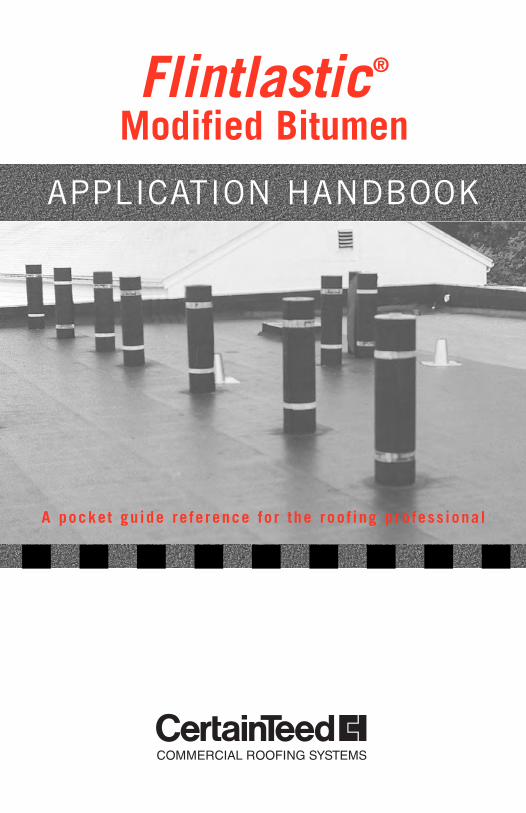
Flintlastic®
Modified Bitumen
APPLICATION HANDBOOK
A pocket gu ide re ference for the roof ing pro fess ional
CertainTeed Flintlastic® Modified Bitumen roofing products represent the finest inquality roofing materials. Beyond quality materials, proper application is the keyto the successful performance of any roofing system.
This pocket guide is intended as a handy reference tool only. It is not all-inclusive, and before installation of any Flintlastic Modified Bitumen RoofSystem the CertainTeed Commercial Roof Systems Specification Manual mustalso be referenced.
CertainTeed Flintlastic Modified Bitumen roofing products are intended for use by professional roofing contractors only. It is the sole responsibility of the appli-cator to exercise all appropriate safety precautions in the application and handling ofroofing products utilizing torches, hot asphalt, cold adhesive and related equipment.For more information concerning safety contact the following agencies:
NRCA (National Roofing Contractors Association)10255 W. Higgins Rd., Ste. 600, Rosemont, IL 60018-5607 Ph. 847-299-9070
MRCA (Midwest Roofing Contractors Association) 4840 W. 15th St., Ste. 1000, Lawrence, KS 66049-3876 Ph. 785-843-4888
NERCA (Northeast Roofing Contractors Association)1400 Hancock St., 7th Flr., Quincy, MA 02169 Ph. 617-479-1478
WSRCA (Western States Roofing Contractors Association)1400 Marsten Rd., Ste. N, Burlingame, CA 94010 Ph. 916-989-6096
ARMA (Asphalt Roofing Manufacturers Association)1156 15th St. NW, Ste. 900, Washington, DC 20005 Ph. 202-572-0354
NFPA (National Fire Protection Association)Batterymarch, Quincy, MA 02269 Ph. 617-770-4543
For a copy of the CertainTeed Commercial Roof Systems Specification Manual,contact the nearest CertainTeed regional office listed below:
South Region5525 MacArthur Blvd. Suite 900Irving, TX 75038(800) 333-ROOF (7663)(972) 580-5645 fax
West Region6400 Stevenson Blvd.Fremont, CA 94538(800) 955-0811(800) 790-3347 fax
North RegionRiverbridge Industrial Center 800 West Front StreetChester, PA 19013(866) 297-ROOF (7663)(610) 874-6170 fax
1
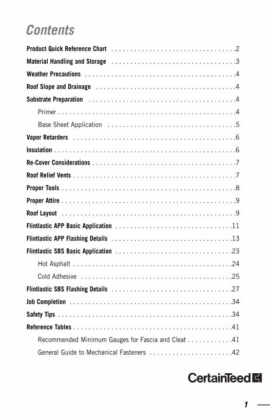
Product Quick Reference Chart . . . . . . . . . . . . . . . . . . . . . . . . . . . . . . . . .2
Material Handling and Storage . . . . . . . . . . . . . . . . . . . . . . . . . . . . . . . . .3
Weather Precautions . . . . . . . . . . . . . . . . . . . . . . . . . . . . . . . . . . . . . . . .4
Roof Slope and Drainage . . . . . . . . . . . . . . . . . . . . . . . . . . . . . . . . . . . . .4
Substrate Preparation . . . . . . . . . . . . . . . . . . . . . . . . . . . . . . . . . . . . . . .4
Primer . . . . . . . . . . . . . . . . . . . . . . . . . . . . . . . . . . . . . . . . . . . . . . .4
Base Sheet Application . . . . . . . . . . . . . . . . . . . . . . . . . . . . . . . . . .5
Vapor Retarders . . . . . . . . . . . . . . . . . . . . . . . . . . . . . . . . . . . . . . . . . . .6
Insulation . . . . . . . . . . . . . . . . . . . . . . . . . . . . . . . . . . . . . . . . . . . . . . . .6
Re-Cover Considerations . . . . . . . . . . . . . . . . . . . . . . . . . . . . . . . . . . . . . .7
Roof Relief Vents . . . . . . . . . . . . . . . . . . . . . . . . . . . . . . . . . . . . . . . . . . .7
Proper Tools . . . . . . . . . . . . . . . . . . . . . . . . . . . . . . . . . . . . . . . . . . . . . .8
Proper Attire . . . . . . . . . . . . . . . . . . . . . . . . . . . . . . . . . . . . . . . . . . . . . .9
Roof Layout . . . . . . . . . . . . . . . . . . . . . . . . . . . . . . . . . . . . . . . . . . . . . .9
Flintlastic APP Basic Application . . . . . . . . . . . . . . . . . . . . . . . . . . . . . . .11
Flintlastic APP Flashing Details . . . . . . . . . . . . . . . . . . . . . . . . . . . . . . . .13
Flintlastic SBS Basic Application . . . . . . . . . . . . . . . . . . . . . . . . . . . . . . .23
Hot Asphalt . . . . . . . . . . . . . . . . . . . . . . . . . . . . . . . . . . . . . . . . . .24
Cold Adhesive . . . . . . . . . . . . . . . . . . . . . . . . . . . . . . . . . . . . . . . .25
Flintlastic SBS Flashing Details . . . . . . . . . . . . . . . . . . . . . . . . . . . . . . . .27
Job Completion . . . . . . . . . . . . . . . . . . . . . . . . . . . . . . . . . . . . . . . . . . .34
Safety Tips . . . . . . . . . . . . . . . . . . . . . . . . . . . . . . . . . . . . . . . . . . . . . .34
Reference Tables . . . . . . . . . . . . . . . . . . . . . . . . . . . . . . . . . . . . . . . . . .41
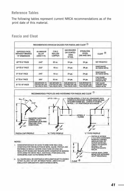
Recommended Minimum Gauges for Fascia and Cleat . . . . . . . . . . . .41
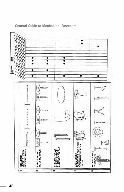
General Guide to Mechanical Fasteners . . . . . . . . . . . . . . . . . . . . . .42
Contents
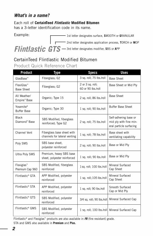
1st letter designates surface, SMOOTH or GRANULAR
2nd letter designates application process, TORCH or MOP
3rd letter designates modifier, SBS or APP
2
What’s in a name?
Each roll of CertainTeed Flintlastic Modified Bitumenhas a 3-letter identification code in its name.
Example:
Flintlastic GTSCertainTeed Flintlastic Modified BitumenProduct Quick Reference Chart
Product Type Specs UsesGlasBase™
FlexiGlas™
Base Sheet
All Weather/Empire™ Base
Yosemite®
Buffer Base
Black Diamond™ Base
Channel Vent
Poly SMS
Ultra Poly SMS
Flexiglas™
Premium Cap 960
Flintlastic® GTA
Flintlastic® STA
Flintlastic® GTS
Flintlastic® GMS
Base Sheet
Base Sheet or Mid Ply
Base Sheet
Buffer Base Sheet
Self-adhering base ormid ply with fine min-eral particle surfacing
Base sheet with ventilating capability
Base or Mid Ply
Base or Mid Ply
Mineral Surfaced Cap Sheet
Mineral Surfaced Cap Sheet
Smooth Surfaced Cap or Mid Ply
Mineral Surfaced Cap
Mineral Surfaced Cap
Flintlastic® and Flexiglas™ products are also available in FR (fire resistant) grade.STA and GMS also available in Premium and Plus.
Fiberglass; G2
Fiberglass; G2
Organic; Type 15
Organic; Type 30
SBS Modified, fiberglassreinforced; Type G2
Fiberglass base sheet withchannels for lateral venting
SBS base sheet, polyester reinforced
Premium, heavy SBS basesheet, polyester reinforced
SBS Modified, fiberglass reinforced
APP Modified, polyesterreinforced
APP Modified, polyesterreinforced
SBS Modified, polyesterreinforced
SBS Modified, polyesterreinforced
3 sq. roll; 75 lbs./roll
2 or 3 sq. roll; 60 or 90 lbs./roll
2 sq. roll; 86 lbs./roll
1 sq. roll; 90 lbs./roll
2 sq. roll; 75 lbs./roll
1 sq. roll; 78 lbs./roll
2 sq. roll; 90 lbs./roll
1 sq. roll; 90 lbs./roll
1sq. roll; 100 lbs./roll
1 sq. roll;105 lbs./roll
1 sq. roll; 90 lbs./roll
3/4 sq. roll; 90 lbs./roll
1 sq. roll; 100 lbs./roll
3
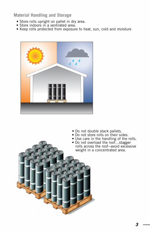
Material Handling and Storage• Store rolls upright on pallet in dry area. • Store indoors in a ventilated area. • Keep rolls protected from exposure to heat, sun, cold and moisture
• Do not double stack pallets.• Do not store rolls on their sides.• Use care in the handling of the rolls.• Do not overload the roof…stagger
rolls across the roof––avoid excessiveweight in a concentrated area.
4
Weather Precautions
Do not attempt application if weather conditions and substrate are not dry.
Do not attempt application if ice, frost, moisture or snow is present.Rolls can be installed in cold weather if conditions are dry, the rolls havenot been allowed to freeze and proper cold weather handling and storageprocedures are followed. Store rolls in a heated area until just prior touse and do not proceed with installation if rolls have been allowed tofreeze or weather conditions are unsuitable.
In extremely warm weather, use caution when walking on freshlyinstalled material to avoid ”tracking” warm asphalt; when torch applyingsmooth APP membrane in very warm weather the installer can walkbeside the sheet being applied (as is the standard torch method withmineral surfaced APP and SBS membrane) to avoid tracking.
Roof Slope and Drainage
All roof decks to which the Flintlastic Modified Bitumen roof system is tobe installed must have a minimum slope of 1/4" per foot (as recom-mended by the NRCA) and must have positive drainage. See also “RoofLayout” on page 9 of this handbook. Greater slope may be necessary aspart of the structural design, depending upon the particular building, toaccommodate rapid and thorough run-off of precipitation.
Substrate Preparation
All surfaces to which the Flintlastic Modified Bitumen is to be installedmust be smooth, dry, free from dust or debris, free from settling or dis-tortion, and free from cracks, knotholes, or other defects.
PrimerConcrete decks must be properly primed with suitable asphalt primer (meeting ASTM D-41) and the primer must be thoroughly dry.
Metal flashings must also be primed with a suitable asphalt primer formetal, and primer must be thoroughly dry and any solvents evaporatedprior to application of membrane flashing. Using sandpaper to roughenthe surface of metal to which torch applied membrane such asFlintlastic STA will be bonded is also recommended.
5
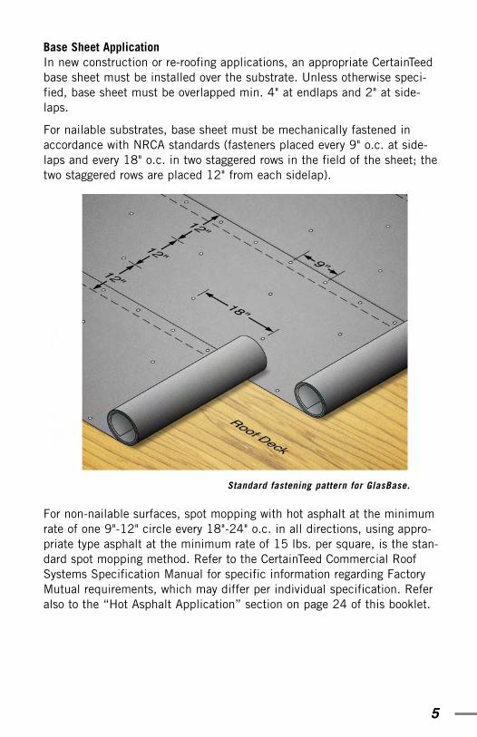
Base Sheet ApplicationIn new construction or re-roofing applications, an appropriate CertainTeedbase sheet must be installed over the substrate. Unless otherwise speci-fied, base sheet must be overlapped min. 4" at endlaps and 2" at side-laps.
For nailable substrates, base sheet must be mechanically fastened inaccordance with NRCA standards (fasteners placed every 9" o.c. at side-laps and every 18" o.c. in two staggered rows in the field of the sheet; thetwo staggered rows are placed 12" from each sidelap).
For non-nailable surfaces, spot mopping with hot asphalt at the minimumrate of one 9"-12" circle every 18"-24" o.c. in all directions, using appro-priate type asphalt at the minimum rate of 15 lbs. per square, is the stan-dard spot mopping method. Refer to the CertainTeed Commercial RoofSystems Specification Manual for specific information regarding FactoryMutual requirements, which may differ per individual specification. Referalso to the “Hot Asphalt Application” section on page 24 of this booklet.
Standard fastening pattern for GlasBase.
6
Vapor Retarders
Vapor retarders are used to help prevent movement of water vapor intothe roof system, where it could condense and cause damage. Determi-nation of the requirement for, and suitability of, a vapor retarder is thesole responsibility of the designer, specifier or architect.
Insulation
All insulations require the use of appropriate base sheet between theinsulation and the new roof system. Insulations must be installed inaccordance with manufacturer instructions, local code and FactoryMutual requirements.
In general, the following rigid board insulation types are acceptable foruse under Flintlastic Modified Bitumen Roof Systems (consult CertainTeedfor specific Factory Mutual requirements):
Fiberglass or Mineral Wool Conforming to Fed. Spec. HH-1-526 and ASTM C726 (CGSB 51.31M)
Wood FiberboardConforming to Fed. Spec. LLL1-535b and ASTM C-208 (CGSB 51.26M)
PerliteConforming to Fed. Spec. HH-1-529 and ASTM C-728
Extruded Polystyrene*Conforming to ASTM C578-85-Type IV (CGSB SB-51.20M Type 2-Type 4)
Expanded Polystyrene*Conforming to Fed. Spec. HH-1-524 and ASTM C578, Min. 1.1 Density (CGSB 51.26M)
Polyisocyanurate*Conforming to Fed Spec. HH-1-1972 and ASTM C-1289 Type II.
*Expanded polystyrene, extruded polystyrene, and polyisocyanurate insu-lations require a separate layer of perlite, fiberglass or wood fiberboardprior to installation of base sheet. Additionally, taping of insulation jointsmay be required. Refer to NRCA and insulation manufacturer require-ments.
*Do not expose flammable or heat sensitive insulations to heat, solvents orflame.
7
In accordance with NRCA recommendations, two separate layers of insula-tion, the first layer mechanically fastened in accordance with NRCA,Factory Mutual and manufacturer specifications, are recommended. PerNRCA guidelines, the joints of the insulation boards in the top layer shouldbe vertically staggered and offset from the joints in the underlying layer;the end joints of adjacent insulation boards should be staggered, and theedges of abutting insulation boards should be in moderate contact.
CertainTeed reserves the right to accept or reject another manufacturer’s insulation as an acceptable substrate for attachment of a CertainTeedCommercial Roof System. CertainTeed Corp. does not warrant perform-ance of another manufacturer’s insulation unless such approval is grant-ed in writing by CertainTeed in advance of installation.
Re-cover Considerations
In re-cover applications, the existing roof system must be the only roof system in place. Two or more existing roofs require a tear-off. It is thecontractor’s responsibility to determine the suitability of any substrate,including verifying the load limitations, local code requirements, andcondition of existing roof system and insulation. If any moisture is pres-ent, the existing roofing and insulation (if insulation is present) must beremoved and the substrate examined. Any needed repairs to the deckmust be completed, and the insulation and existing membrane replacedwith new, dry materials, prior to application of the new roof system.
If re-roofing over the existing roof system is deemed feasible, installationof appropriate insulation or re-cover board may be required. Base sheetis a requirement in all re-cover applications. Refer to the CertainTeedCommercial Roof Systems Specification Manual for complete details.
Roof Relief Vents
If roof relief vents are deemed appropriate they should be of a suitabletype with minimum 4" flange and weather resistant hood, spaced 20'from roof edge perimeter and every 40' o.c. thereafter.
8
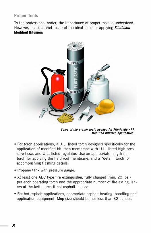
Proper Tools
To the professional roofer, the importance of proper tools is understood.However, here’s a brief recap of the ideal tools for applying FlintlasticModified Bitumen:
• For torch applications, a U.L. listed torch designed specifically for theapplication of modified bitumen membrane with U.L. listed high-pres-sure hose, and U.L. listed regulator. Use an appropriate length fieldtorch for applying the field roof membrane, and a “detail” torch foraccomplishing flashing details.
• Propane tank with pressure gauge.
• At least one ABC type fire extinguisher, fully charged (min. 20 lbs.)per each operating torch and the appropriate number of fire extinguish-ers at the kettle area if hot asphalt is used.
• For hot asphalt applications, appropriate asphalt heating, handling andapplication equipment. Mop size should be not less than 32 ounces.
Some of the proper tools needed for Flintlastic APPModified Bitumen application.
9
• A roofer’s hooked blade knife (the hooked blade is ideal for cutting the membrane).
• A roofer’s trowel with beveled edges and rounded tip (allows smoothingof details without cutting or marking the membrane); trowels that allowadequate room between the roofer’s gloved fingers and the warm mem-brane are the best.
Proper Attire
• Long pants and long sleeved shirts.
• Leather work shoes with synthetic or smooth leather soles.
• Leather work gloves that adequately shield the wrist area. Refer also tothe ”Safety” section of this booklet on page 34 for information regard-ing proper work attire.
Roof Layout
As with most types of roof installations, Flintlastic Modified Bitumen roofinstallation begins at the low point of the roof with successive rolls installedso that no laps are against the flow of water. When membrane is appliedwith hot asphalt, where roof slope is 1" per foot or less, sidelaps areinstalled perpendicular to the direction of the roof slope. In situations wherethe roof slope exceeds 1" per foot, rolls are installed with the sidelaps run-ning parallel to the slope direction. Torch applied membrane can beinstalled with sidelaps perpendicular to the slope where roof slope is 2" perfoot or less (over 2" install sidelaps parallel to roof slope direction).
Additionally, where roof slope exceeds 1" per foot for hot asphalt appliedFlintlastic Modified Bitumen membrane or 2" per foot for torch appliedFlintlastic Modified Bitumen, “back-nailing” of membrane is required.Refer to the General Requirements section of the CertainTeed CommercialRoof Systems Specification Manual for back-nailing guidelines.
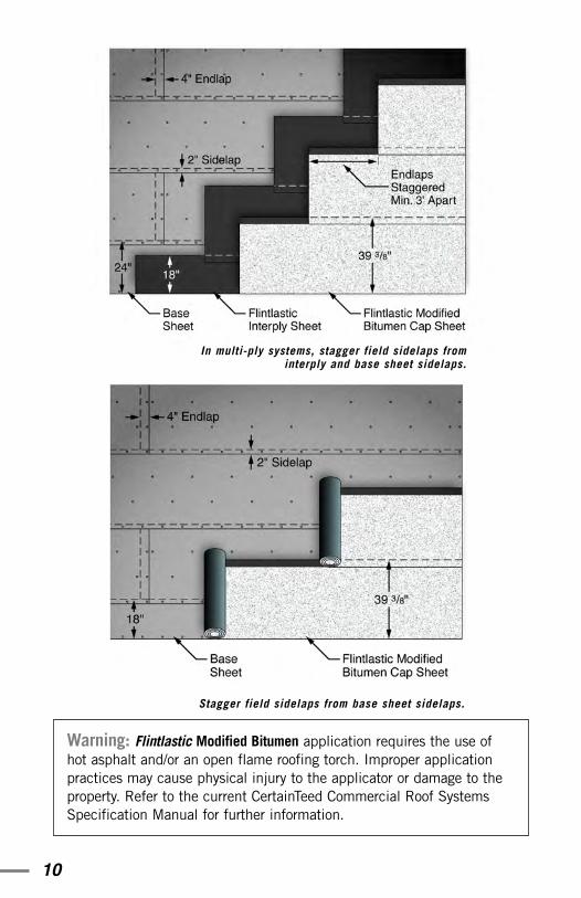
Endlaps are to be staggered. If cap sheet endlaps are aligned, they mustbe capped with a full roll width of Flintlastic Modified Bitumen. In multi-ply applications, membrane sidelaps must also be staggered. See illus-trations on the following page.
10
In multi-ply systems, stagger field sidelaps frominterply and base sheet sidelaps.
Warning: Flintlastic Modified Bitumen application requires the use ofhot asphalt and/or an open flame roofing torch. Improper applicationpractices may cause physical injury to the applicator or damage to theproperty. Refer to the current CertainTeed Commercial Roof SystemsSpecification Manual for further information.
Stagger field sidelaps from base sheet sidelaps.
11
Basic Application: Flintlastic APP Modified BitumenPrepare the substrate as described on pages 4-5.
Flintlastic APP Modified Bitumen must be applied using a professionalroofer’s torch. Use of hand-held roofing torches is recommended andaffords the most control. If multiple burner torching machines are utilizedcare must be taken to assure uniform heat application and to avoid over-heating of the membrane.
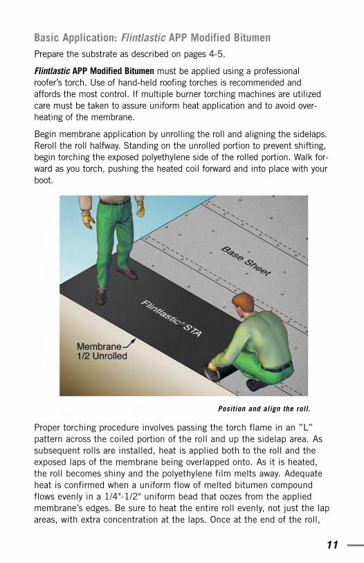
Begin membrane application by unrolling the roll and aligning the sidelaps.Reroll the roll halfway. Standing on the unrolled portion to prevent shifting,begin torching the exposed polyethylene side of the rolled portion. Walk for-ward as you torch, pushing the heated coil forward and into place with yourboot.
Proper torching procedure involves passing the torch flame in an ”L”pattern across the coiled portion of the roll and up the sidelap area. Assubsequent rolls are installed, heat is applied both to the roll and theexposed laps of the membrane being overlapped onto. As it is heated,the roll becomes shiny and the polyethylene film melts away. Adequateheat is confirmed when a uniform flow of melted bitumen compoundflows evenly in a 1/4"-1/2" uniform bead that oozes from the appliedmembrane’s edges. Be sure to heat the entire roll evenly, not just the lapareas, with extra concentration at the laps. Once at the end of the roll,
Position and align the roll.
12
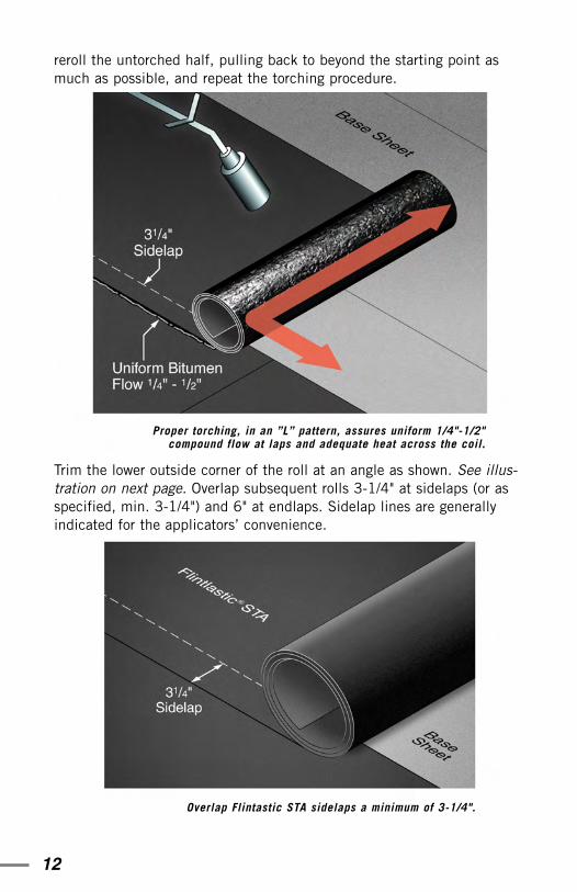
reroll the untorched half, pulling back to beyond the starting point asmuch as possible, and repeat the torching procedure.
Trim the lower outside corner of the roll at an angle as shown. See illus-tration on next page. Overlap subsequent rolls 3-1/4" at sidelaps (or asspecified, min. 3-1/4") and 6" at endlaps. Sidelap lines are generallyindicated for the applicators’ convenience.
Overlap Flintastic STA sidelaps a minimum of 3-1/4".
Proper torching, in an ”L” pattern, assures uniform 1/4"-1/2"compound flow at laps and adequate heat across the coil.
13
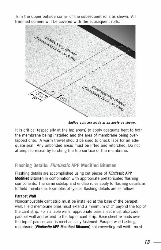
Trim the upper outside corner of the subsequent rolls as shown. Alltrimmed corners will be covered with the subsequent rolls.
Endlap cuts are made at an angle as shown.
It is critical (especially at the lap areas) to apply adequate heat to boththe membrane being installed and the area of membrane being over-lapped onto. A warm trowel should be used to check laps for an ade-quate seal. Any unbonded areas must be lifted and retorched. Do notattempt to reseal by torching the top surface of the membrane.
Flashing Details: Flintlastic APP Modified Bitumen
Flashing details are accomplished using cut pieces of Flintlastic APPModified Bitumen in combination with appropriate prefabricated flashingcomponents. The same sidelap and endlap rules apply to flashing details asto field membrane. Examples of typical flashing details are as follows:
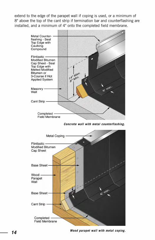
Parapet Wall Noncombustible cant strip must be installed at the base of the parapetwall. Field membrane plies must extend a minimum of 2" beyond the top ofthe cant strip. For nailable walls, appropriate base sheet must also coverparapet wall and extend to the top of cant strip. Base sheet extends overthe top of parapet and is mechanically fastened. Parapet wall flashingmembrane (Flintlastic APP Modified Bitumen) not exceeding roll width must
14
extend to the edge of the parapet wall if coping is used, or a minimum of8" above the top of the cant strip if termination bar and counterflashing areinstalled, and a minimum of 4" onto the completed field membrane.
Concrete wall with metal counterflashing.
Wood parapet wall with metal coping.
15
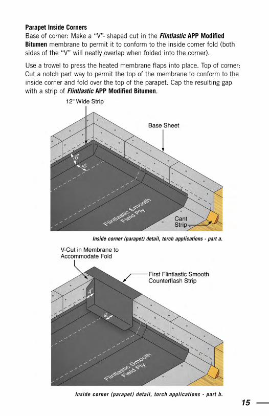
Parapet Inside Corners Base of corner: Make a “V”- shaped cut in the Flintlastic APP ModifiedBitumen membrane to permit it to conform to the inside corner fold (bothsides of the “V” will neatly overlap when folded into the corner).
Use a trowel to press the heated membrane flaps into place. Top of corner: Cut a notch part way to permit the top of the membrane to conform to theinside corner and fold over the top of the parapet. Cap the resulting gapwith a strip of Flintlastic APP Modified Bitumen.
Inside corner (parapet) detail, torch applications - part a.
Inside corner (parapet) detail, torch applications - part b.

16
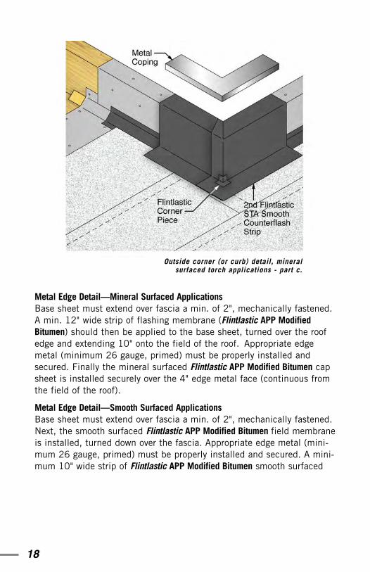
Inside corner (parapet) detail, torch applications - part c.
Inside corner (parapet) detail, torch applications - part d.
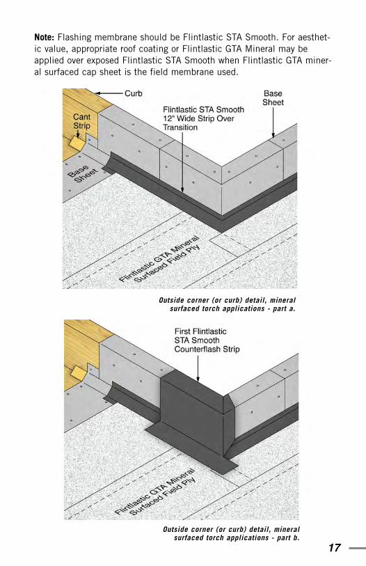
Outside Corners and CurbsAt outside corners such as curbs, the reverse situation occurs from thatof inside corners. The “V”-shaped cut goes at the top of the membranestrip and the notch or straight slice at the bottom, since the membraneis folding the opposite way. In this case, cap the opening at the bottomof the strip which extends onto the field of the roof a minimum of 4".
17
Note: Flashing membrane should be Flintlastic STA Smooth. For aesthet-ic value, appropriate roof coating or Flintlastic GTA Mineral may beapplied over exposed Flintlastic STA Smooth when Flintlastic GTA miner-al surfaced cap sheet is the field membrane used.
Outside corner (or curb) detail, mineralsurfaced torch applications - part a.
Outside corner (or curb) detail, mineralsurfaced torch applications - part b.
18
Metal Edge Detail—Mineral Surfaced Applications Base sheet must extend over fascia a min. of 2", mechanically fastened.A min. 12" wide strip of flashing membrane (Flintlastic APP ModifiedBitumen) should then be applied to the base sheet, turned over the roofedge and extending 10" onto the field of the roof. Appropriate edgemetal (minimum 26 gauge, primed) must be properly installed andsecured. Finally the mineral surfaced Flintlastic APP Modified Bitumen capsheet is installed securely over the 4" edge metal face (continuous fromthe field of the roof).
Metal Edge Detail—Smooth Surfaced Applications Base sheet must extend over fascia a min. of 2", mechanically fastened.Next, the smooth surfaced Flintlastic APP Modified Bitumen field membraneis installed, turned down over the fascia. Appropriate edge metal (mini-mum 26 gauge, primed) must be properly installed and secured. A mini-mum 10" wide strip of Flintlastic APP Modified Bitumen smooth surfaced
Outside corner (or curb) detail, mineralsurfaced torch applications - part c.
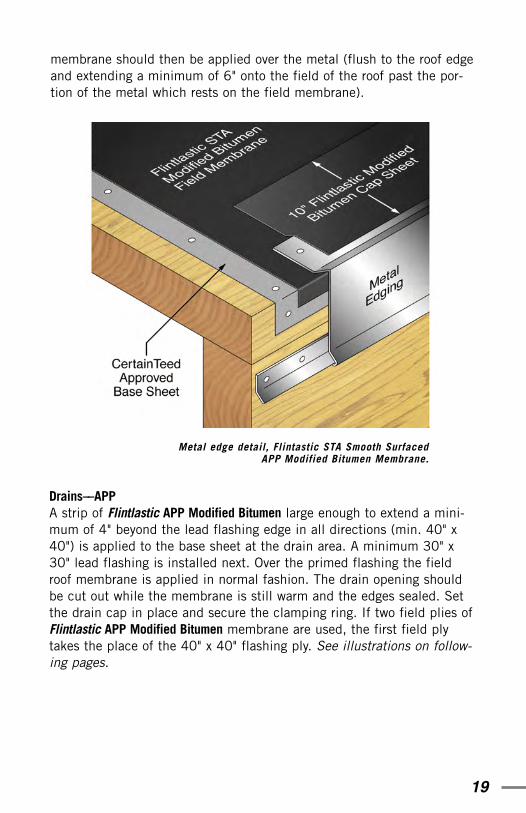
19
membrane should then be applied over the metal (flush to the roof edgeand extending a minimum of 6" onto the field of the roof past the por-tion of the metal which rests on the field membrane).
Metal edge detail, Flintastic STA Smooth SurfacedAPP Modified Bitumen Membrane.
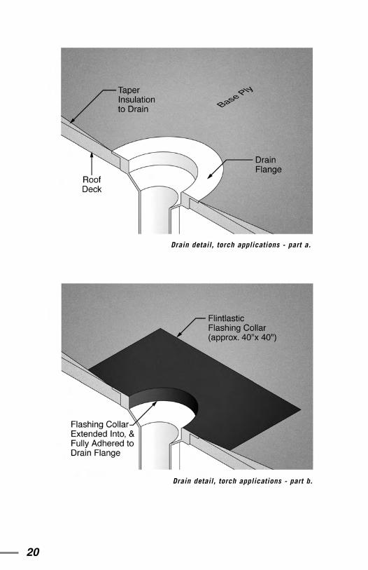
Drains––APPA strip of Flintlastic APP Modified Bitumen large enough to extend a mini-mum of 4" beyond the lead flashing edge in all directions (min. 40" x40") is applied to the base sheet at the drain area. A minimum 30" x30" lead flashing is installed next. Over the primed flashing the fieldroof membrane is applied in normal fashion. The drain opening shouldbe cut out while the membrane is still warm and the edges sealed. Setthe drain cap in place and secure the clamping ring. If two field plies ofFlintlastic APP Modified Bitumen membrane are used, the first field plytakes the place of the 40" x 40" flashing ply. See illustrations on follow-ing pages.
20
Drain detail, torch applications - part a.
Drain detail, torch applications - part b.
21
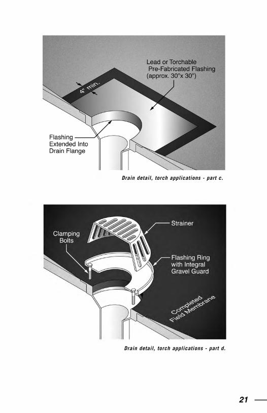
Drain detail, torch applications - part c.
Drain detail, torch applications - part d.
22
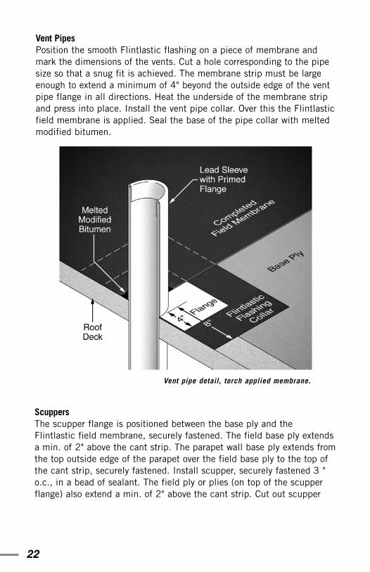
Vent PipesPosition the smooth Flintlastic flashing on a piece of membrane andmark the dimensions of the vents. Cut a hole corresponding to the pipesize so that a snug fit is achieved. The membrane strip must be largeenough to extend a minimum of 4" beyond the outside edge of the ventpipe flange in all directions. Heat the underside of the membrane stripand press into place. Install the vent pipe collar. Over this the Flintlasticfield membrane is applied. Seal the base of the pipe collar with meltedmodified bitumen.
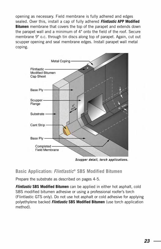
Scuppers The scupper flange is positioned between the base ply and theFlintlastic field membrane, securely fastened. The field base ply extendsa min. of 2" above the cant strip. The parapet wall base ply extends fromthe top outside edge of the parapet over the field base ply to the top ofthe cant strip, securely fastened. Install scupper, securely fastened 3 "o.c., in a bead of sealant. The field ply or plies (on top of the scupperflange) also extend a min. of 2" above the cant strip. Cut out scupper
Vent pipe detail, torch applied membrane.
23
opening as necessary. Field membrane is fully adhered and edgessealed. Over this, install a cap of fully adhered Flintlastic APP ModifiedBitumen membrane that covers the top of the parapet and extends downthe parapet wall and a minimum of 4" onto the field of the roof. Securemembrane 9" o.c. through tin discs along top of parapet. Again, cut outscupper opening and seal membrane edges. Install parapet wall metalcoping.
Basic Application: Flintlastic® SBS Modified Bitumen
Prepare the substrate as described on pages 4-5.
Flintlastic SBS Modified Bitumen can be applied in either hot asphalt, coldSBS modified bitumen adhesive or using a professional roofer’s torch(Flintlastic GTS only). Do not use hot asphalt or cold adhesive for applyingpolyethylene backed Flintlastic SBS Modified Bitumen (use torch applicationmethod).
Scupper detail, torch applications.
24
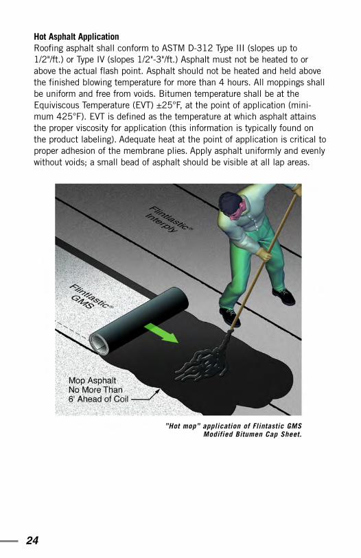
Hot Asphalt Application Roofing asphalt shall conform to ASTM D-312 Type III (slopes up to1/2"/ft.) or Type IV (slopes 1/2"-3"/ft.) Asphalt must not be heated to orabove the actual flash point. Asphalt should not be heated and held abovethe finished blowing temperature for more than 4 hours. All moppings shallbe uniform and free from voids. Bitumen temperature shall be at theEquiviscous Temperature (EVT) ±25°F, at the point of application (mini-mum 425°F). EVT is defined as the temperature at which asphalt attainsthe proper viscosity for application (this information is typically found onthe product labeling). Adequate heat at the point of application is critical toproper adhesion of the membrane plies. Apply asphalt uniformly and evenlywithout voids; a small bead of asphalt should be visible at all lap areas.
”Hot mop” application of Flintastic GMSModified Bitumen Cap Sheet.
25
Solid moppings require a minimum of 25 lbs./100 ft2 hot asphalt applica-tion.
Spot mopping of base sheet, when appropriate, is generally accomplishedusing a minimum of 9"-12" diameter circles spaced every 18"-24" o.c. inthree staggered rows. (Certain Factory Mutual listed specifications may havedifferent requirements; refer to the CertainTeed Commercial Roof SystemsSpecification Manual for complete details).
Excessive, prolonged heating of asphalt can have a detrimental effect on theintegrity of the product. Additionally, excessive heating of asphalt poses a serious flash or fire hazard. Refer also to the ”Safety” section beginning onpage 34 of this handbook for more information.
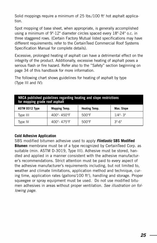
The following chart shows guidelines for heating of asphalt by type (Type III and IV):
Cold Adhesive Application SBS modified bitumen adhesive used to apply Flintlastic SBS ModifiedBitumen membrane must be of a type recognized by CertainTeed Corp. assuitable (min. ASTM D-3019, Type III). Adhesive must be stored, han-dled and applied in a manner consistent with the adhesive manufactur-er’s recommendations. Strict attention must be paid to every aspect ofthe adhesive manufacturer’s requirements including, but not limited to,weather and climate limitations, application method and technique, cur-ing time, application rates (gallons/100 ft2), handling and storage. Propersqueegee or spray equipment must be used. Do not use modified bitu-men adhesives in areas without proper ventilation. See illustration on fol-lowing page.
NRCA published guidelines regarding heating and slope restrictions for mopping grade roof asphalt
ASTM D312 Type
Type III
Type IV
Mopping Temp.
400°- 450°F
400°- 475°F
Max. Slope
1/4"- 3"
3"-6"
Heating Temp.
500°F
500°F
26
Membrane application requirements such as endlap and sidelap widths,number and order of plies and flashing details are the same for both hotand cold applications.
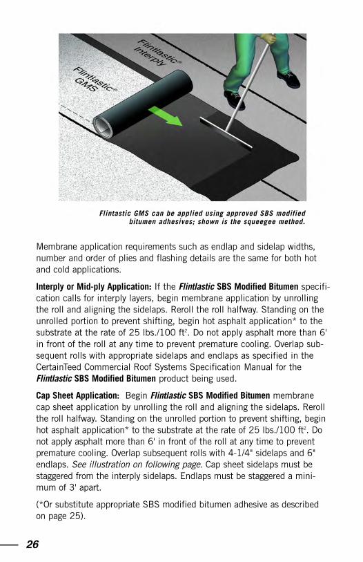
Interply or Mid-ply Application: If the Flintlastic SBS Modified Bitumen specifi-cation calls for interply layers, begin membrane application by unrollingthe roll and aligning the sidelaps. Reroll the roll halfway. Standing on theunrolled portion to prevent shifting, begin hot asphalt application* to thesubstrate at the rate of 25 lbs./100 ft2. Do not apply asphalt more than 6'in front of the roll at any time to prevent premature cooling. Overlap sub-sequent rolls with appropriate sidelaps and endlaps as specified in theCertainTeed Commercial Roof Systems Specification Manual for theFlintlastic SBS Modified Bitumen product being used.
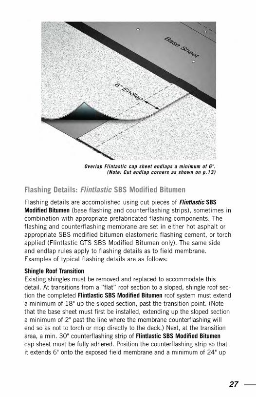
Cap Sheet Application: Begin Flintlastic SBS Modified Bitumen membranecap sheet application by unrolling the roll and aligning the sidelaps. Rerollthe roll halfway. Standing on the unrolled portion to prevent shifting, beginhot asphalt application* to the substrate at the rate of 25 lbs./100 ft2. Donot apply asphalt more than 6' in front of the roll at any time to preventpremature cooling. Overlap subsequent rolls with 4-1/4" sidelaps and 6"endlaps. See illustration on following page. Cap sheet sidelaps must bestaggered from the interply sidelaps. Endlaps must be staggered a mini-mum of 3' apart.
(*Or substitute appropriate SBS modified bitumen adhesive as describedon page 25).
Flintastic GMS can be applied using approved SBS modifiedbitumen adhesives; shown is the squeegee method.
27
Flashing Details: Flintlastic SBS Modified Bitumen
Flashing details are accomplished using cut pieces of Flintlastic SBSModified Bitumen (base flashing and counterflashing strips), sometimes incombination with appropriate prefabricated flashing components. Theflashing and counterflashing membrane are set in either hot asphalt orappropriate SBS modified bitumen elastomeric flashing cement, or torchapplied (Flintlastic GTS SBS Modified Bitumen only). The same sideand endlap rules apply to flashing details as to field membrane.Examples of typical flashing details are as follows:
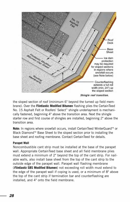
Shingle Roof Transition Existing shingles must be removed and replaced to accommodate thisdetail. At transitions from a ”flat” roof section to a sloped, shingle roof sec-tion the completed Flintlastic SBS Modified Bitumen roof system must extenda minimum of 18" up the sloped section, past the transition point. (Notethat the base sheet must first be installed, extending up the sloped sectiona minimum of 2" past the line where the membrane counterflashing willend so as not to torch or mop directly to the deck.) Next, at the transitionarea, a min. 30" counterflashing strip of Flintlastic SBS Modified Bitumencap sheet must be fully adhered. Position the counterflashing strip so thatit extends 6" onto the exposed field membrane and a minimum of 24" up
Overlap Flintastic cap sheet endlaps a minimum of 6".(Note: Cut endlap corners as shown on p.13)
28
the sloped section of roof (minimum 6" beyond the turned up field mem-brane). Over the Flintlastic Modified Bitumen flashing plies the CertainTeedNo. 15 Asphalt Felt or Roofers’ Select™ shingle underlayment is mechani-cally fastened, beginning 4" above the transition area. Next the shinglestarter row and first course of shingles are installed, beginning 2" above thetransition area.
Note: In regions where snowfall occurs, install CertainTeed WinterGuardTM orBlack DiamondTM Base Sheet to the sloped section prior to installing thebase sheet and roofing membrane. Contact CertainTeed for details.
Parapet Wall Noncombustible cant strip must be installed at the base of the parapetwall. Appropriate CertainTeed base sheet and all field membrane pliesmust extend a minimum of 2" beyond the top of the cant strip. For nail-able walls, also install base sheet from the top of the cant strip to theoutside edge of the parapet wall. Parapet wall flashing membrane(Flintlastic SBS Modified Bitumen) not exceeding roll width must extend tothe edge of the parapet wall if coping is used, or a minimum of 8" abovethe top of the cant strip if termination bar and counterflashing areinstalled, and 4" onto the field membrane.
Shingle roof transition.

29
Parapet Inside CornersBase of corner: Make a “V”- shaped cut in the Flintlastic SBS ModifiedBitumen membrane to permit it to conform to the inside corner fold (bothsides of the “V” will neatly overlap when folded into the corner).
Secure the membrane flaps using SBS modified bitumen flashing adhe-sive. Top of corner: Cut a notch part way to permit the top of the mem-brane to conform to the inside corner and fold over the top of the para-pet. Cap the resulting gap with a strip of Flintlastic SBS Modified Bitumen.Flashing strips must extend a minimum of 4" onto the field membrane.
Outside Corners and CurbsAt outside corners such as curbs, the base sheet extends 2" beyond thetop of the cant strip, and for nailable curbs a separate ply of base sheetextends from the inside edge of the top of the curb to the top of thecant strip. The field Flintlastic plies and cap sheet extend 2" above thetop of the cant strip. Next a 2 ply base and cap flashing (Flintlastic)cover the top of the curb and extend a minimum of 4" onto the field ofthe roof. Install appropriate metal cap.
Example of raised curb detail.
30
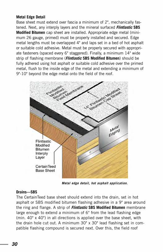
Metal Edge DetailBase sheet must extend over fascia a minimum of 2", mechanically fas-tened. Next, any interply layers and the mineral surfaced Flintlastic SBSModified Bitumen cap sheet are installed. Appropriate edge metal (mini-mum 26 gauge, primed) must be properly installed and secured. Edgemetal lengths must be overlapped 4" and laps set in a bed of hot asphaltor suitable cold adhesive. Metal must be properly secured with appropri-ate fasteners (spaced every 6" staggered). Finally, a minimum 14" widestrip of flashing membrane (Flintlastic SBS Modified Bitumen) should befully adhered using hot asphalt or suitable cold adhesive over the primedmetal, flush to the inside edge of the metal and extending a minimum of9"-10" beyond the edge metal onto the field of the roof.
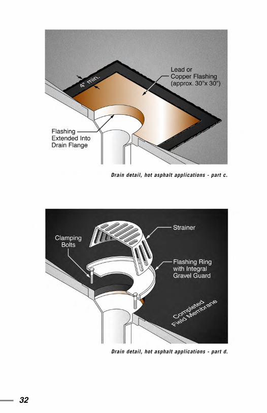
Drains––SBSThe CertainTeed base sheet should extend into the drain, set in hotasphalt or SBS modified bitumen flashing adhesive in a 9" area aroundthe ring and flange. A strip of Flintlastic SBS Modified Bitumen membranelarge enough to extend a minimum of 6" from the lead flashing edge(min. 40" x 40") in all directions is applied over the base sheet, withthe drain hole cut out. A minimum 30" x 30" lead flashing set in com-patible flashing compound is secured next. Over this, the field roof
Metal edge detail, hot asphalt application.
31
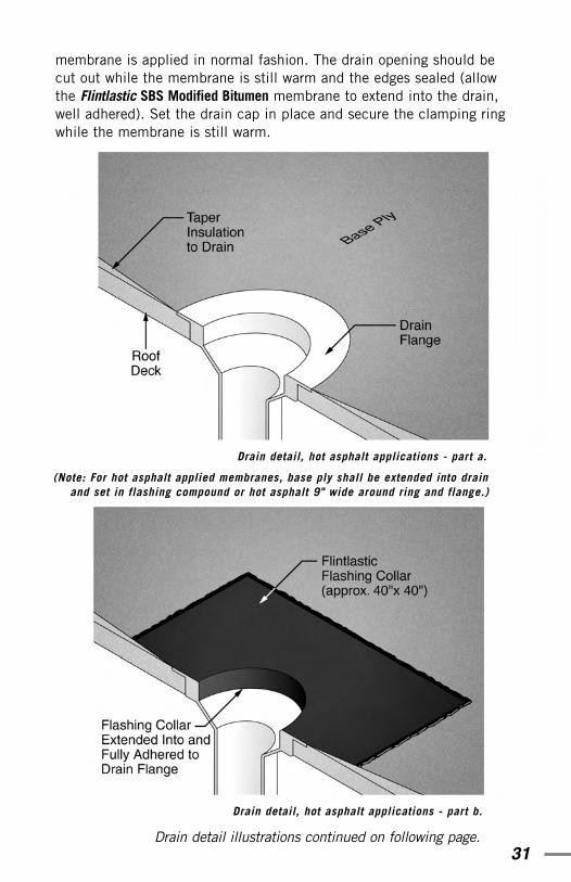
Drain detail, hot asphalt applications - part a.
(Note: For hot asphalt applied membranes, base ply shall be extended into drainand set in flashing compound or hot asphalt 9" wide around ring and flange.)
Drain detail, hot asphalt applications - part b.
membrane is applied in normal fashion. The drain opening should becut out while the membrane is still warm and the edges sealed (allowthe Flintlastic SBS Modified Bitumen membrane to extend into the drain,well adhered). Set the drain cap in place and secure the clamping ringwhile the membrane is still warm.
Drain detail illustrations continued on following page.
32
Drain detail, hot asphalt applications - part d.
Drain detail, hot asphalt applications - part c.
33
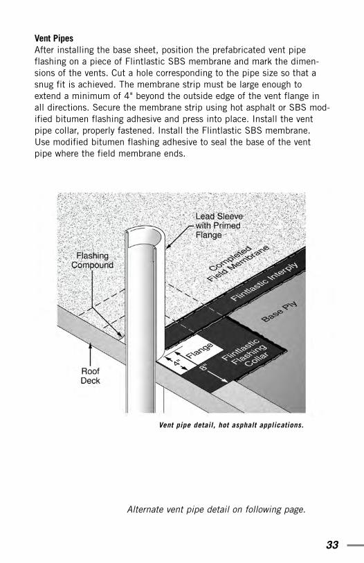
Vent PipesAfter installing the base sheet, position the prefabricated vent pipeflashing on a piece of Flintlastic SBS membrane and mark the dimen-sions of the vents. Cut a hole corresponding to the pipe size so that asnug fit is achieved. The membrane strip must be large enough toextend a minimum of 4" beyond the outside edge of the vent flange inall directions. Secure the membrane strip using hot asphalt or SBS mod-ified bitumen flashing adhesive and press into place. Install the ventpipe collar, properly fastened. Install the Flintlastic SBS membrane.Use modified bitumen flashing adhesive to seal the base of the ventpipe where the field membrane ends.
Vent pipe detail, hot asphalt applications.
Alternate vent pipe detail on following page.

34
Job CompletionBefore considering any roof project complete, walk the roof and check lapsfor any signs of unbonded areas (a trowel can be used for this purpose).Check flashing details to be sure they are secure. Leave roof and premisesclean and free of any roofing debris (daily). Be sure all vent caps are snugand drain screens securely in place.
Safety TipsAs stated in the warning on page 10, use of propane torches and hotasphalt requires thorough knowledge and skill in all aspects of safety withrespect to their use and handling. CertainTeed recommends that profession-al applicators receive the CERTA torch safety training as offered by theMRCA (see inside cover) and participate in all asphalt heating and handlingsafety training available through their local roofing associations, ARMA andNFPA (see inside cover), local fire departments, OSHA and the NRCA,among others. Under no circumstances should Flintlastic Modified Bitumenroofing application be attempted by “do-it-yourselfers” or any persons other
Alternate detail, lead pipe flashing.
35
than professional, trained roofers. It is the roofing contractor’s sole responsibili-ty to be certain all crew members are appropriately trained in safe and properuse of propane torching and hot asphalt equipment and procedures.
The following safety tips are a general reference only and are in no way all-inclusive.
Job WatchWhen the torch application method is used, it is important to remember that carelessness resulting in heat entering a crevice may cause con-cealed smoldering. A supervisor trained in fire safety should remain onthe jobsite a minimum of 4 hours after cessation of torching to check forany signs of smoke, smoldering or fire. The safety check should utilizeinfra-red thermometers and should include a thorough interior check ofthe attic, crawl spaces and return air ducts in addition to the roof areawhere torches have been utilized. Prior to leaving the jobsite the con-tractor must be certain that all chance of fire, including smoldering fire,has been eliminated.
Personnel•Proper clothing, including work boots, long pants, long sleeved shirts
and gloves, must be worn. It is the contractor’s responsibility to requireemployees to wear proper attire.
•Workmen, other than the torch operator, should be not closer than 3feet to the torch flame.
• It is the contractor’s responsibility to observe all fire prevention policiesand practices during the installation of the roof system.
• It is the contractor’s responsibility to train, instruct and warn employ-ees on the use and handling of propane torching equipment.
•Extra caution must be used when torching near exposed edges of insu-lation to prevent flame from coming into contact with any flammablematerial. Contact for any length of time with lead or other materialsaffected by heat must be avoided.
•Never use the equipment in an enclosed area.
•Refer to NFPA S8 "Standard for the Storage and Handling of LiquifiedPetroleum Gas" and appropriate publications of the National PropaneGas Association (1600 Eisenhower, Suite 100, Lisle, IL 60532, ph.630-515-0600) and the National Fire Protection Association(Batterymarch, Quincy, MA 02269).
36
Fire Department Regulations•Written notice should be given to the local fire department and any
necessary permits must be acquired.
• The required number of fire extinguishers shall be on the roof at alltimes.
•Portable smoke detectors should be installed in attics as required bythe local fire department.
•All supervisors and crew members on the jobsite shall have fire safetytraining. The crew supervisor or foreman must remain on the jobsite atleast 4 hours after cessation of torching, and shall check the completeroof and attic area for any signs of smoke or smoldering.
•No flammable liquids shall be stored or used on the roof (excludingLPG in approved containers). Any LPG not in use shall be stored onthe ground.
Tools and Equipment•Be certain that all torching equipment is in good working order.
•Be certain cylinder valves are clean.
•Use an adjustable pilot with a complete shut-off valve.
•Use a flint or electronic ignitor to light the torch. Matches or dispos-able lighters are unsafe and not acceptable.
•Do not use any equipment without an operating pressure gauge.
•Do not operate any pressure gauge beyond the top of its scale, near excessive heat (above 150°F) or where there is excessive vibration.
•Use a torch stand to direct the torch flame upward when the torch isbriefly set down. Shut off completely when not in use.
•Propane tanks must be secured in an upright position, placed a mini-mum of 10' from the torch flame at all times.
•Secure propane tanks when on the roof.
• Increase the size of the propane tank if necessary to prevent frost fromoccurring. Never heat the tank with a torch or any other device, and neverput the torch flame anywhere near the tank.
•Never turn a propane tank on its side to increase pressure. Liquid could escape.
37
•Protect cylinder valves, and where possible use cylinders that havevalve protection welded to the cylinder. Never lift a cylinder by thevalve. Valves are made of soft brass and are easily broken.
•Do not tighten brass fittings too tightly with a wrench.
•Do not attempt to put out a cylinder fire if it cannot be done withouttipping the tank; Call the fire department.
•Never fill a propane cylinder that is in need of repair.
•Never lay a torch to rest on a gas cylinder.
•Use only hose intended for use with LP gas.
•Do not use hose longer than 50'.
•Use an adjustable, U.L. listed regulator with the torch.
•Keep vent in pressure regulator unobstructed at all times.
•Make sure flow of gas through regulator is in the proper direction.Directional flow is indicated on the regulator.
•Use a soap solution to check for gas leaks before lighting torch. Thencheck for proper operation of the torch. Never check for leaks usinglighter or matches.
• If a leak occurs, stop work immediately and repair all relevant parts.Do not use any torch equipment that is leaking gas at any fitting.
•Stop torching immediately if any propane odor is detected.
•Check hoses frequently for wear and tear, and do not allow torch flameto come into contact with them. Keep hoses free of kinks and do notallow heavy equipment to roll over them. Also check hoses for anysigns of burned or charred areas.
•Be aware of the difference between liquid and vapor gas bottles anddispensing equipment.
•Treat the torch as if it is always burning. In sunlight it can be difficultto see the flame, and when working near mechanical equipment youcannot always hear the torch.
•Never leave a torch unattended.
•Never lay a torch over the edge of the roof.
•Do not use a trowel as a torch stand.
38
•When shutting off the torch, close the propane cylinder valve first andlet the remaining gas burn out of the hose before closing the torchvalve.
•Keep an ABC or Halon fire extinguisher on the roof, readily accessibleto each worker using a torch at all times. Make sure the extinguisher isreadily accessible, but not so close to the torch or propane equipmentthat it cannot be safely accessed in the event of a fire.
•When using a dry chemical type extinguisher, direct the chemicalstream at the base of the fire from a safe distance of about 10' to 15'.Sweep the fire away from you, starting at its nearest point and movingthe chemical stream toward the furthest point.
•Do not use soda acid fire extinguisher—it spreads the flame.
•Check all equipment for wear and tear and repair or replace as neces-sary.
•Use extreme caution when working with torches in areas where youcannot see. Heat the membrane away from the area and then apply itto the flashing. Do not torch directly into any crevice or unsafe areawhere flame could be sucked in.
•Protect all equipment from damage; store in a toolbox.
Building Safety •Use noncombustible type cant strips such as perlite or fiberglass and
cover them with appropriate CertainTeed base sheet.
•Use appropriate CertainTeed base sheet over all nailable deck typesincluding plywood, wood, lightweight insulating concrete, and over allinsulations and any flammable surface.
•Use noncombustible insulation, and cover it with appropriateCertainTeed base sheet (see also pages 6-7).
• Install metal flashings to penetrations or protect flashings with tight-fitting collar prior to torching.
•Use a small detail torch when applying flashing details.
•Be certain all air conditioning units, exhaust fans, and air intake fansin the work area are shut off at the roof control.
39
•Shield air conditioning units and other protrusions with perlite or simi-lar panels when using the torch around them. Heat roofing membraneaway from air conditioning units, fans, soil pipes, and all other protru-sions, and set in place while still hot. Use extreme caution to preventthe flame from being pulled into the building interior.
• Feather seams around details with a warm trowel.
•When torching at flashings, corners or voids in the roof or roof deck,never torch directly. Always torch the membrane to be applied andthen adhere it to the corner or joint.
•Use caution when torching near pipes in the event there is suctionpresent. Failure to utilize base sheet as required by manufacturer spec-ifications is extremely dangerous as the base sheet provides a protec-tive covering for underlying combustibles.
•Examine the roof substrate for any void, hole or gap and fill it withnoncombustible or perlite cant strip. Cover the cant strip withCertainTeed Type G2 fiberglass base sheet.
•Never torch directly to insulation. Appropriate CertainTeed base sheetis required over all insulations. RIC/TIMA recommends that polyure-thane and polyisocyanurate insulations be isolated from the roof mem-brane via the use of an additional layer of noncombustible insulationand CertainTeed base sheet, or an interim base ply acceptable to themembrane manufacturer.
• Install CertainTeed Type G2 fiberglass base sheet over all flammablesurfaces and insulations. Base sheet must fit tightly around all deckopenings and must turn up parapet walls so that torch flame cannotflash down into and start a fire underneath the deck.
•Never torch into any area where you cannot see; do not use the torchin areas such as under air conditioning units or behind counterflash-ing.
•Don’t torch directly to wood fiber cant strips or wood fiber insulations.
•Don’t torch directly to any cant strip, insulation, wood or any otherflammable surface.
•Never torch near gas lines or electrical wires.
40
•Never torch to flammable surfaces such as EPS insulations.
•Never torch around flammable vents.
•Do not point the torch under rooftop equipment.
•Do not direct the torch down open roof penetrations, or near openingsaround roof penetrations.
•Never point the torch at low flashings where there is an overhang andflame could get up under the counterflashing (such as around skylightsor prefabricated curbs with fiberboard sidewall insulation).
• Torching equipment is made for roofing application only and shouldnot be used for drying out a roof or as a preheater torch.
• Never apply modified bitumen products directly over exposed conduitsor pipes laying on the roof deck.
•LP gas is heavier than air. Do not work in an enclosed area where gas can accumulate.
•Do not rest an operating torch directly on the membrane. There is danger of fire and danger of damaging the membrane.
•Don’t lay an operating torch on an open penetration on the roof. If the penetration is part of an air intake system, the flame could be suckedinto the building.
Additional Hot Asphalt Considerations• Maintain kettle and tanker temperatures less than 25°F below the actu-
al flash point of the material used.
• NEVER heat materials to or above the actual flash point.
• Don’t maintain asphalt at high temperatures for prolonged periods oftime.
• Don’t allow asphalt to stand in luggers for long periods of times.
• Use insulated hot bitumen transport lines to help maintain acceptablebitumen temperature at point of application.
• Circulate bitumen while heating.
41
Reference Tables
Fascia and Cleat
The following tables represent current NRCA recommendations as of theprint date of this material.
42
General Guide to Mechanical FastenersS
TAN
DA
RD
(RO
UN
DH
EA
D)
RO
OF
ING
NA
ILS
LA
RG
EH
EA
DR
OO
FIN
GN
AIL
S
PN
EU
MA
TIC
AL
LYD
RIV
EN
STA
PL
EA
ND
TAP
EO
RC
AP
BA
SE
SH
EE
TFA
ST
EN
ER
SF
OR
SO
ME
CE
ME
NT
ITIO
US
RO
OF
DE
CK
S
SE
LF
-LO
CK
ING
FAS
TE
NE
RS

43
General Guide to Mechanical Fasteners (continued)

44
General Guide to Mechanical Fasteners (continued)

45
General Guide to Mechanical Fasteners (continued)

750 E. Swedesford RoadP.O. Box 860Valley Forge, PA 19482(610) 431-7000
Architectural Support(800) 233-8990
Fax on Demand(800) 947-0057
www.certainteed.com
© 2002 CertainTeed Corporation COMM-019