Embed Size (px)
Citation preview

Page 1 of 30
ORWELL ENGINEERING SOLUTIONS LTD
FLOAT BATH EQUIPMENT SUPPLY
DOCUMENT No. – ORW/1000/C00-1000 REV 00
SUPPLY SPECIFICATION
Unit 1, Farriers Way, Bridle Road, Liverpool L30 4XL

Page 2 of 30
Table of Contents
DOCUMENT OVERVIEW ..................................................................................................... 3
GENERAL EQUIPMENT SUPPLY STATEMENT ................................................................. 4
EQUIPMENT SPECIFICATIONS .......................................................................................... 4
CANAL AREA .................................................................................................................... 4
FULL FLOAT CANAL DESIGN AND SUPPLY PACKAGE ................................................ 4
MANUFACTURE AND SUPPLY PACKAGE ...................................................................... 6
TWEEL RAISING GEAR ................................................................................................ 6
CANAL CASING AND SUPPORT STEELWORK ........................................................... 7
SPOUT & LIP CASINGS ................................................................................................ 8
ANCILLARY CANAL AREA EQUIPMENT ...................................................................... 8
CANAL CRANE UNIT .................................................................................................... 9
BATH AREA .................................................................................................................... 11
FULL BATH BLOCKING DESIGN AND SUPPLY PACKAGE .......................................... 11
MANUFACTURE AND SUPPLY PACKAGE .................................................................... 12
BATH BLOCKING FIXING EQUIPMENT ..................................................................... 12
GENERAL BATH EQUIPMENT ....................................................................................... 14
EXIT LIP PLATE .......................................................................................................... 14
SEALED LEHR ............................................................................................................ 15
SIDE SEALING ............................................................................................................ 17
MOTORISED POSITIONER UNITS ............................................................................. 19
BATH GRAPHITES ...................................................................................................... 20
HOT END COOLERS .................................................................................................. 21
EXIT END COOLERS .................................................................................................. 22
LINEAR MOTORS & CARRIAGES .............................................................................. 23
TOP ROLL MACHINES ............................................................................................... 25
RIBBON EDGE BURNERS .......................................................................................... 26
BATH PERISCOPES ................................................................................................... 27
BATH TV MONITORING SYSTEM .............................................................................. 28
INFORMATION REQUIRED BY ORWELL FROM CLIENT ................................................. 29
DRAWINGS REQUIRED BY ORWELL FROM CLIENT ...................................................... 30

Page 3 of 30
DOCUMENT OVERVIEW
This document provides a specification and outline overview of the Bath Equipment
that Orwell Engineering Solutions Ltd will be providing to the client as part of the
supply contract.
This document also identifies information and drawings that the client will need to
provide (or make available) to Orwell Engineering Solutions Ltd prior to the
commencement by Orwell of any equipment manufacture. This information is
required by Orwell Engineering Solutions Ltd to enable Orwell to finalise and
complete the necessary and correct manufacturing drawings for the equipment to be
compatible with the bath structure and process line.
This document when completed and agreed between the client and Orwell
Engineering Solutions Ltd will act as the definitive design specification after which
any changes to information and drawings referred to in this document may result in
supply contract variations being requested by Orwell Engineering Solutions Ltd and
a delay in the equipment supply programme.

Page 4 of 30
GENERAL EQUIPMENT SUPPLY STATEMENT
All equipment is manufactured in accordance with Machinery Directive 2006/42/EC
and where applicable Low Voltage Directive 2006/95/EC. Equipment will be CE
marked and an EC Declaration of Conformity certificate issued to the client.
All water cooled equipment that enters the Float Bath is helium and pressure tested,
test certificates will be issued to the client. All Orwell testers are fully trained and
certified in the use of the testing equipment.
All equipment unless stated in the exclusions will be supplied with hoses to connect
to a local site supply / return services connection. The size, type and location of site
services connections to be agreed with the client.
Orwell Engineering Solutions Ltd will provide maintenance routines, lubrication
schedules and a recommended spares list where appropriate for each piece of
equipment. All other documentation required must be clearly specified by the client.
All equipment will be supplied packed (suitable for export) ex works UK.
EQUIPMENT SPECIFICATIONS
CANAL AREA
FULL FLOAT CANAL DESIGN AND SUPPLY PACKAGE
A complete canal package can be offered which includes design, manufacture and
supply of a complete canal. Alternatively a manufacture and supply can be offered
for the canal to the client’s drawings.
SCOPE OF SUPPLY (DESIGN AND SUPPLY)
The canal will be designed and agreed and equipment provided as follows:-
Canal casing.
Canal casing support steelwork.
Canal refractories.
Spout and lip casings.
Spout and lip refractories.
Page 5 of 30
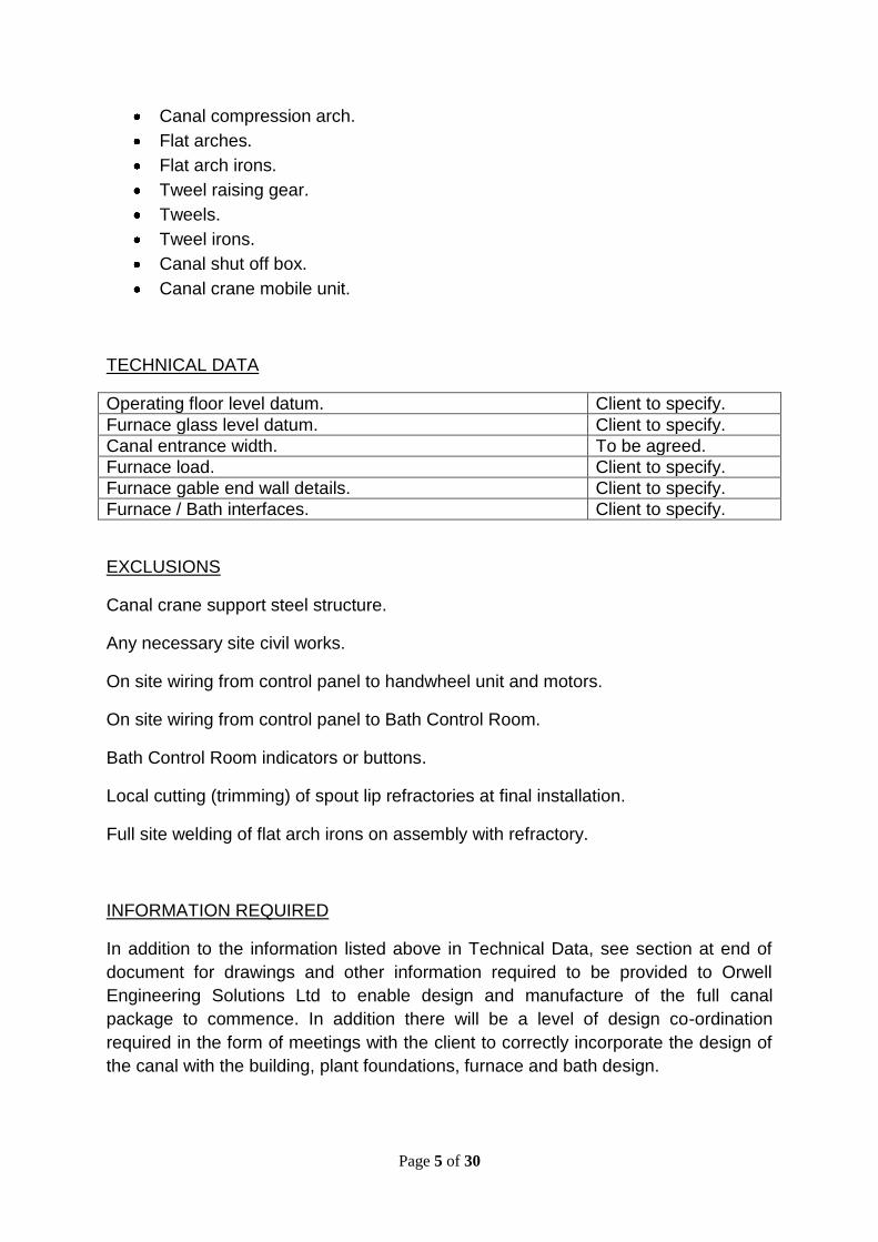
Canal compression arch.
Flat arches.
Flat arch irons.
Tweel raising gear.
Tweels.
Tweel irons.
Canal shut off box.
Canal crane mobile unit.
TECHNICAL DATA
Operating floor level datum. Client to specify.
Furnace glass level datum. Client to specify.
Canal entrance width. To be agreed.
Furnace load. Client to specify.
Furnace gable end wall details. Client to specify.
Furnace / Bath interfaces. Client to specify.
EXCLUSIONS
Canal crane support steel structure.
Any necessary site civil works.
On site wiring from control panel to handwheel unit and motors.
On site wiring from control panel to Bath Control Room.
Bath Control Room indicators or buttons.
Local cutting (trimming) of spout lip refractories at final installation.
Full site welding of flat arch irons on assembly with refractory.
INFORMATION REQUIRED
In addition to the information listed above in Technical Data, see section at end of
document for drawings and other information required to be provided to Orwell
Engineering Solutions Ltd to enable design and manufacture of the full canal
package to commence. In addition there will be a level of design co-ordination
required in the form of meetings with the client to correctly incorporate the design of
the canal with the building, plant foundations, furnace and bath design.

Page 6 of 30
MANUFACTURE AND SUPPLY PACKAGE
TWEEL RAISING GEAR
SCOPE OF SUPPLY
The tweel raising gear will be provided to Orwell Engineering Solutions design as
follows:-
The tweel raising gear will operate two tweels each of which is operated
independently of the other. The main units of the equipment will be situated beneath
the canal and bath house floor. The tweel raising gear will comprise of drive motors
which through a series of shafts operate screw jacks which control two vertical rods
which raise and lower each tweel. The tweel height will be capable of being remotely
controlled from the Bath Control Room with the facility to manually control from a
handwheel unit sited on the bath house floor on the operating side of the bath. The
vertical tweel rods will be supplied with support bearings which will be mounted on
brackets attached to the canal casing. A tweel support beam is mounted across each
pair of vertical rods by means of lock nuts and spring units from which each tweel
(supplied by others) is suspended. The spring units provide a cushioning effect
should the tweel be brought into contact with the canal / spout bottom blocks.
The range of travel of the tweels (when remotely operated from the Control Room) is
restricted by limit switches. The position of the tweel relative to the spout bottom
block level is indicated digitally in the Bath Control Room and also on the handwheel
unit by a counter reading.
The tweel raising gear supply includes a local control panel.
Alternatively, Orwell can manufacture and supply the tweel raising gear to the
Client’s drawings and specifications.
TECHNICAL DATA
Operating floor level datum. Client to specify.
Spout bottom block level datum. Client to specify.
Spout side block level datum. Client to specify.
Front tweel range of travel. 550mm.
Front tweel range of jack movement. ~760mm.
Rear tweel range of travel. 750mm.
Rear tweel range of jack movement. ~960mm.
Distance between tweels (in direction of glass flow). Client to specify.
Distance between tweel rods (across glass flow). 3100mm.
Accuracy of front tweel travel. +/- 0.1mm.

Page 7 of 30
Mains voltage. Client to specify.
Control Voltage. Client to specify.
EXCLUSIONS
The following are not included as part of the Tweel Raising Gear supply:-
Refractory and / or steel tweels.
Any necessary civil works.
On site wiring from control panel to handwheel unit and motors.
On site wiring from control panel to Bath Control Room.
Bath Control Room indicators or buttons.
INFORMATION REQUIRED
In addition to the information listed above in Technical Data, see section at end of
document for drawings and other information required to be provided to Orwell
Engineering Solutions Ltd to enable manufacture of the tweel raising gear to
commence to Orwell’s design. For the alternative option a full set of the Client’s
manufacturing drawings and specifications for all parts will be required to enable
manufacture to commence.
CANAL CASING AND SUPPORT STEELWORK
SCOPE OF SUPPLY
The canal casing will be provided as follows:-
The canal casing will be manufactured according to the client’s drawings and
specification. As part of the canal casing supply the supporting steelwork and
expansion rollers for the canal casing can also be provided manufactured to the
client’s drawings.
TECHNICAL DATA
All technical data will be as specified by the client on the drawings.

Page 8 of 30
EXCLUSIONS
The following are not included as part of the supply:-
Canal Refractories.
INFORMATION REQUIRED
Client drawings and specifications for all parts required.
SPOUT & LIP CASINGS
SCOPE OF SUPPLY
The spout and lip casings will be provided as follows:-
The spout and lip casings will be manufactured according to the client’s drawings
and specification. The casings will be supplied complete with all ancillary items as
specified on the client’s drawings. The water box(es) built into the casings will be
subjected to a pressure test before acceptance.
TECHNICAL DATA
All technical data will be as specified by the client on the drawings.
EXCLUSIONS
The following are not included as part of the supply:-
Spout and lip Refractories.
INFORMATION REQUIRED
Client drawings and specifications for all parts required.
ANCILLARY CANAL AREA EQUIPMENT
SCOPE OF SUPPLY
The following ancillary items will be provided as follows:-

Page 9 of 30
Flat arch irons will be manufactured according to the client’s drawings and
specification.
Tweel irons will be manufactured according to the client’s drawings and specification.
Canal shut off water box will be manufactured according to the client’s drawings and
specification.
The canal shut off water box is subjected to a pressure test before acceptance.
TECHNICAL DATA
All technical data will be as specified by the client on the drawings.
EXCLUSIONS
The following are not included as part of the supply:-
Refractories.
Support steelwork for canal shut off box.
INFORMATION REQUIRED
Client drawings and specifications for all parts required.
CANAL CRANE UNIT
SCOPE OF SUPPLY
The canal crane unit will be provided as follows:-
A manual single girder overhead crane complete with travelling trolley and hook to
be mounted on a supporting steel structure (designed and supplied by others).
TECHNICAL DATA
Crane unit capacity. 3,000 Kg.
Operation. Manual.
Number of rail wheels. 4
Hook type. Single point.
Page 10 of 30
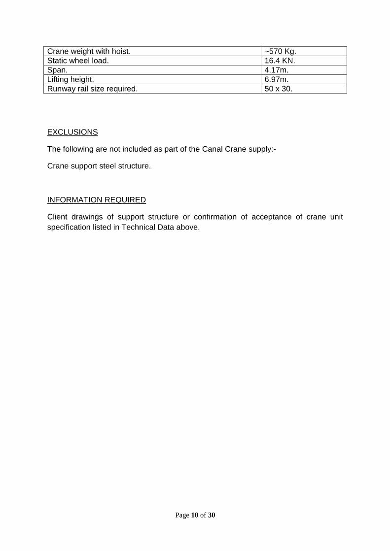
Crane weight with hoist. ~570 Kg.
Static wheel load. 16.4 KN.
Span. 4.17m.
Lifting height. 6.97m.
Runway rail size required. 50 x 30.
EXCLUSIONS
The following are not included as part of the Canal Crane supply:-
Crane support steel structure.
INFORMATION REQUIRED
Client drawings of support structure or confirmation of acceptance of crane unit
specification listed in Technical Data above.

Page 11 of 30
BATH AREA
FULL BATH BLOCKING DESIGN AND SUPPLY PACKAGE
A complete bath blocking package can be offered which includes design and supply
of bath blocks and all ancillary items necessary for blocking. Alternatively a
manufacture and supply of the ancillary items only can be provided.
SCOPE OF SUPPLY (DESIGN AND SUPPLY)
The bath blocking layout will be designed and agreed, individual blocks detailed and
equipment provided as follows:-
Bath bottom and sideblocks (including a level of spares).
Welding studs and ferrules.
Blocking nuts and washers.
Graphite sleeves.
Bath bottom block spacers.
Bath sidewall block spacers.
Bath block packers.
Stud welding machine.
Stud welding gun and adaptors.
Stud torque testing equipment.
Torque spanner.
Cements.
TECHNICAL DATA
Operating floor level datum. Client to specify.
Furnace glass level datum. Client to specify.
Furnace load. Client to specify.
Ribbon widths required (max / min) Client to specify.
Ribbon thicknesses to be produced. Client to specify.
Saleable glass quality market (e.g. MT) Client to specify.
Clear / Tint Client to specify.
Future requirements Client to specify.

Page 12 of 30
EXCLUSIONS
Bath support steel structure.
Bath civil works.
Bath Casing.
Bath roof.
Bath block cement ramming equipment.
Specialised bath blocking installation equipment.
Local cutting (trimming) of bath blocks at installation.
Installation (see later section)
INFORMATION REQUIRED
In addition to the information listed above in Technical Data, see section at end of
document for drawings and other information required to be provided to Orwell
Engineering Solutions Ltd to enable design and manufacture of the full bath blocking
to commence. In addition there will be a level of design co-ordination required in the
form of meetings with the client to correctly incorporate the blocking design with the
building, plant foundations, bath casing, furnace and lehr design.
ADDITIONAL SUPPORT AVAILABLE
Orwell Engineering Solutions Ltd is able to offer supervisors to come to site for bath
blocking installation and also a stud welding expert who will provide training on the
bath block stud welding machine and method.
MANUFACTURE AND SUPPLY PACKAGE
BATH BLOCKING FIXING EQUIPMENT
SCOPE OF SUPPLY
The Bath Blocking Fixing Equipment will be provided as follows:-
One Stud Welding Machine.
Page 13 of 30
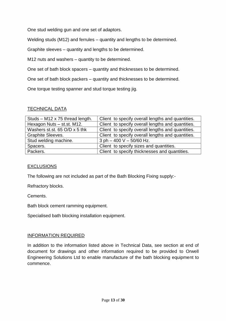
One stud welding gun and one set of adaptors.
Welding studs (M12) and ferrules – quantity and lengths to be determined.
Graphite sleeves – quantity and lengths to be determined.
M12 nuts and washers – quantity to be determined.
One set of bath block spacers – quantity and thicknesses to be determined.
One set of bath block packers – quantity and thicknesses to be determined.
One torque testing spanner and stud torque testing jig.
TECHNICAL DATA
Studs – M12 x 75 thread length. Client to specify overall lengths and quantities.
Hexagon Nuts – st.st. M12. Client to specify overall lengths and quantities.
Washers st.st. 65 O/D x 5 thk Client to specify overall lengths and quantities.
Graphite Sleeves. Client to specify overall lengths and quantities.
Stud welding machine. 3 ph – 400 V – 50/60 Hz.
Spacers. Client to specify sizes and quantities.
Packers. Client to specify thicknesses and quantities.
EXCLUSIONS
The following are not included as part of the Bath Blocking Fixing supply:-
Refractory blocks.
Cements.
Bath block cement ramming equipment.
Specialised bath blocking installation equipment.
INFORMATION REQUIRED
In addition to the information listed above in Technical Data, see section at end of
document for drawings and other information required to be provided to Orwell
Engineering Solutions Ltd to enable manufacture of the bath blocking equipment to
commence.
Page 14 of 30
GENERAL BATH EQUIPMENT
EXIT LIP PLATE
SCOPE OF SUPPLY
The Exit Lip Plate will be provided as follows:-
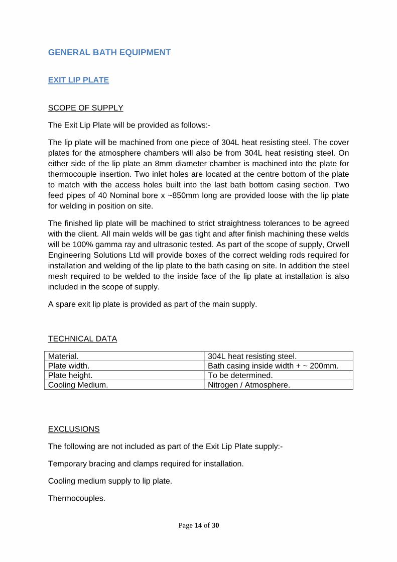
The lip plate will be machined from one piece of 304L heat resisting steel. The cover
plates for the atmosphere chambers will also be from 304L heat resisting steel. On
either side of the lip plate an 8mm diameter chamber is machined into the plate for
thermocouple insertion. Two inlet holes are located at the centre bottom of the plate
to match with the access holes built into the last bath bottom casing section. Two
feed pipes of 40 Nominal bore x ~850mm long are provided loose with the lip plate
for welding in position on site.
The finished lip plate will be machined to strict straightness tolerances to be agreed
with the client. All main welds will be gas tight and after finish machining these welds
will be 100% gamma ray and ultrasonic tested. As part of the scope of supply, Orwell
Engineering Solutions Ltd will provide boxes of the correct welding rods required for
installation and welding of the lip plate to the bath casing on site. In addition the steel
mesh required to be welded to the inside face of the lip plate at installation is also
included in the scope of supply.
A spare exit lip plate is provided as part of the main supply.
TECHNICAL DATA
Material. 304L heat resisting steel.
Plate width. Bath casing inside width + ~ 200mm.
Plate height. To be determined.
Cooling Medium. Nitrogen / Atmosphere.
EXCLUSIONS
The following are not included as part of the Exit Lip Plate supply:-
Temporary bracing and clamps required for installation.
Cooling medium supply to lip plate.
Thermocouples.

Page 15 of 30
INFORMATION REQUIRED
See section at end of document for drawings and information required to be provided
to Orwell Engineering Solutions Ltd to enable manufacture of the exit lip plate to
commence.
SEALED LEHR
SCOPE OF SUPPLY
The Sealed Lehr will be provided as follows:-
The dross box assembly, hood, drape lifting gear assembly (including lehr drape
lifting gear for front of lehr) and all drapes.
The dross box is a fabricated mild steel structure that will be welded to the end of the
bath casing (supplied by others) and be supported on steelwork and rollers (supplied
by others) to allow for expansion of the bath.
The assembled dross box will be supplied with bearings mounted out from the sides
of the dross box to support the three lift out rollers (supplied by others). The design
of the bearing support plates will be such that each lift height roller can be raised or
lowered from its datum position. The dross box houses three channels located under
each roller that hold springs, seals and hairpin coolers, all of which are replaceable
during normal glass production. A simple trolley is provided for the installation and
removal of the lift out rollers from the non drive side of the plant. Three runway
beams (provided by others) attached to the main bath supporting steelwork and
extending out onto the non drive side over each lift out roller position are required to
assist in the lift out roller installation and removal.
Removable doors are fitted in the sides of the dross box for the removal of dross and
cullet that collects inside the bottom of the box. The underside, upstream and
downstream sides of the dross box are insulated on the outside faces.
An insulated, fabricated steel hood will be provided which will be fitted over the dross
box, the bottom of the hood is aligned with the bottom of the bath roof exit lintel. The
hood is welded to the bath roof casing and supported by turnbuckles from the drape
raising gear frame steelwork above.
The gap between the dross box and the hood is sealed by insulated boxes hung
from the hood and resting on the dross box.
The hood houses four sealing drapes, one drape is positioned over the exit lip of the
bath with the other three drapes each positioned over the three lift out rollers. A
drape raise frame and mechanism is located above the hood to raise and lower the

Page 16 of 30
drapes. The frame is bolted to the bath roof casing and supported by four hanger
rods (identical to the bath roof hanger rods). These hanger rods are supported from
the bath roof support steelwork (provided by others). A fifth sealing drape is provided
with its own drape raise frame and mechanism for fitting onto the front of the lehr.
All drapes will be operated manually to raise and lower from hand wheels accessible
from bath operating floor on the drive side of the plant. All drapes and drape carriers
will be capable of being replaced during normal glass production. The water cooled
bearings are subjected to a helium and pressure test before acceptance.
TECHNICAL DATA
Dross box width (inside). To suit bath casing width (inside).
Hood width (outside). To suit bath roof casing (outside).
Distance from end of bath casing to centre line of 1st lift out roller.
Client to specify.
Lift out roller centres. Client to specify.
Lift out roller datum settings. Client to specify.
Lift out roller adjustment. +/- 20mm from datum.
Lift out roller diameter. 305mm.
Width of drape (hood). Client to specify.
Width of drape (lehr). Client to specify.
Depth of drape (hood). Client to specify.
Depth of drape (lehr). Client to specify.
Drape movement range. Top of lift out roller to flush with hood bottom.
EXCLUSIONS
The following are not included as part of the Sealed Lehr supply:-
Dross box support steel and expansion rollers.
Bath supporting roof steelwork extension over dross box area.
Hanger rod assemblies (as bath roof hanger assemblies).
Lift out rollers.
Lift out roller installation runway beams and lifting hoists.

Page 17 of 30
INFORMATION REQUIRED
In addition to the information listed above in Technical Data, see section at end of
document for drawings and other information required to be provided to Orwell
Engineering Solutions Ltd to enable manufacture of the sealed lehr to commence.
SIDE SEALING
SCOPE OF SUPPLY
The side seals fit into the gap down the sides of the bath between the bath bottom
casing and the bath roof casing to help form a gas tight seal of the bath. A side seal
comprises of a stainless steel insulated box with a front mild steel plate with handles.
Side seals for specific items of equipment are included in each particular equipment
package.
General side seals for the remainder of the bath will be provided as follows:-
Tin thermocouple side seals.
Viewing window side seal where possible as follows
o A minimum of one in each bay of the bath in the wide end.
o A spout viewing window seal in Bay 1.
o A window seal each side of every top roll machine.
o A window seal each side of every fence, flag and pusher.
o A window seal each side of a bank of narrow end coolers on the launch
side of the bath.
o A window seal in the centre of a narrow end cooler bank on the non
launch side of the bath.
o One either side of the bath looking at the exit lip.
Note windows are secured in place by steel wedges.
A bath pressure sampling point side seal.
Blank side seals of various sizes.
Make-up seals of 50mm, 75mm, 100mm and 150mm long.
Bath block cover plates for the hot end of the bath.
Mounting and sealing components for thermocouples.
High level atmosphere cooled window seals to be welded into the bath roof as
follows:-
One either side of the front roof lintel.
One each side of the bath roof in the hot end taper.

Page 18 of 30
One each side of the bath roof in the shoulder section.
Sufficient blank side seals in this package are provided to seal up the bath for warm
up and start up.
The maximum length of any individual side seal will be no greater than 606mm to
allow for manual handling.
In addition to side seals Orwell Engineering Solutions Ltd will also supply in this
package cover plates in mild steel to be welded to the bath casing at the hot end
over the exposed blocks at the start of the bath.
As part of the side seal supply Orwell Engineering Solutions will provide a general
arrangement drawing of the side seals for bath warm up.
TECHNICAL DATA
Side seal box material. Stainless steel grade 304L.
Front cover plate material. Mild steel.
Insulation material. Body soluble insulation.
Bath side seal gap. Client to specify.
Distance between bath casing and roof casing sealing angles.
Client to specify.
EXCLUSIONS
The following are not included as part of the Side Seal Package supply:-
Toughened wired glass windows for side seals and high level bath roof seals.
Bath side seal sealing materials to seal the gaps around the side seal boxes and the
bath and roof casings.
INFORMATION REQUIRED
In addition to the information listed above in Technical Data, see section at end of
document for drawings and other information required to be provided to Orwell
Engineering Solutions Ltd to enable manufacture of the side seal package to
commence.

Page 19 of 30
MOTORISED POSITIONER UNITS
SCOPE OF SUPPLY
Motorised Positioner units will be provided as follows:-
Two units for use with pushers.
Two units for use with fences.
The Motorised Positioner Unit is a fabricated bracket that is bolted to the bath bottom
casing equipment mounting bars. The bracket incorporates a precision machined
track which carries a carriage driven by a leadscrew and air motor. The carriage has
a clamping plate on top to which a pusher or fence pipe water cooled beam can be
mounted. A pneumatic panel for controlling the air motor is mounted to the bracket.
Included in the supply will be water cooled pusher and fence beams complete with
graphite blocks and side seals. The water cooled beams are subjected to a helium
and pressure test before acceptance.
TECHNICAL DATA
Drive. Air motor.
Positioner mounting bracket bolt centres. 165mm.
Pusher / Fence beam length. ~ 3800mm.
Pusher / Fence graphite blocks. CS Grade graphite.
Bath side seal gap. Client to specify.
Distance between bath casing and roof casing sealing angles.
Client to specify.
Control Voltage. Client to specify.
EXCLUSIONS
The following are not included as part of the Motorised Positioner Unit supply:-
On site wiring of solenoid valves from local junction box.
INFORMATION REQUIRED
In addition to the information listed above in Technical Data, see section at end of
document for drawings and other information required to be provided to Orwell
Engineering Solutions Ltd to enable manufacture of the motorised positioned units to
commence.

Page 20 of 30
BATH GRAPHITES
SCOPE OF SUPPLY
Bath Graphite components will be provided as follows:-
Side Liners complete with straps and temporary holding straps.
Graphite Barriers.
Tin pump bodies and ancillary components including tin drain pocket cover plates.
Full Depth Flags including all support bracketry.
Submerged Flags including all support bracketry.
TECHNICAL DATA
Side liners. CS Grade. Client to provide detail drawing.
Side liner straps and temporary straps. Stainless steel 304L.
Barriers. CS Grade. Client to provide detail drawing.
Tin pump and ancillary graphites. CS Grade.
Full Depth Flags. CS Grade – 1000mm long
Submerged Flags. CS Grade - Client to specify lengths and quantities required.
EXCLUSIONS
The following are not included as part of the Bath Graphite supply:-
Tin drain pocket (normally part of bath casing supply).
General tin drain equipment.
INFORMATION REQUIRED
In addition to the information listed above in Technical Data, see section at end of
document for drawings and other information required to be provided to Orwell
Engineering Solutions Ltd to enable manufacture of the bath graphite items to
commence.

Page 21 of 30
HOT END COOLERS
SCOPE OF SUPPLY
Hot End Coolers will be provided as follows:-
Hot end coolers are fabricated water cooled beams that enter the bath through a
letterbox side seal welded into the bath roof at the front of the bath (Bays 1 and 2).
Each beam is mounted on a carriage manually operated by means of a chain and
trolley mechanism attached to a runway beam. These runway beams are supported
at the bath end by bolting to the main bath steelwork (supplied by others), the other
end being supported by a tie rod arrangement connected from the bath main
steelwork. The letterbox side seal for each cooler is a hinged door arrangement
opened by the weight of the cooler entering the bath. This side seal is welded around
slots cut into the side of the bath roof with the locations being defined by the Client
and the bath roof supplier.
There are 4 coolers provided (2 each side of the bath). The coolers are designed to
meet “head on” in the centre of the bath during glass production.
All coolers are subjected to a helium and pressure test before acceptance.
TECHNICAL DATA
Number of coolers / carriages. 4 (2 each side of bath).
Hot end bath width. Client to specify.
Cooler coverage. Coolers to meet in centre of bath.
Operation. Manual – chain and trolley.
EXCLUSIONS
The following are not included as part of the Hot End Cooler supply:-
Main Bath Support Steelwork.
Bath Roof Casing (Slots).
INFORMATION REQUIRED
In addition to the information listed above in Technical Data, see section at end of
document for drawings and other information required to be provided to Orwell
Engineering Solutions Ltd to enable manufacture of the hot end coolers to
commence.
Page 22 of 30
EXIT END COOLERS
SCOPE OF SUPPLY
Exit End Coolers will be provided as follows:-
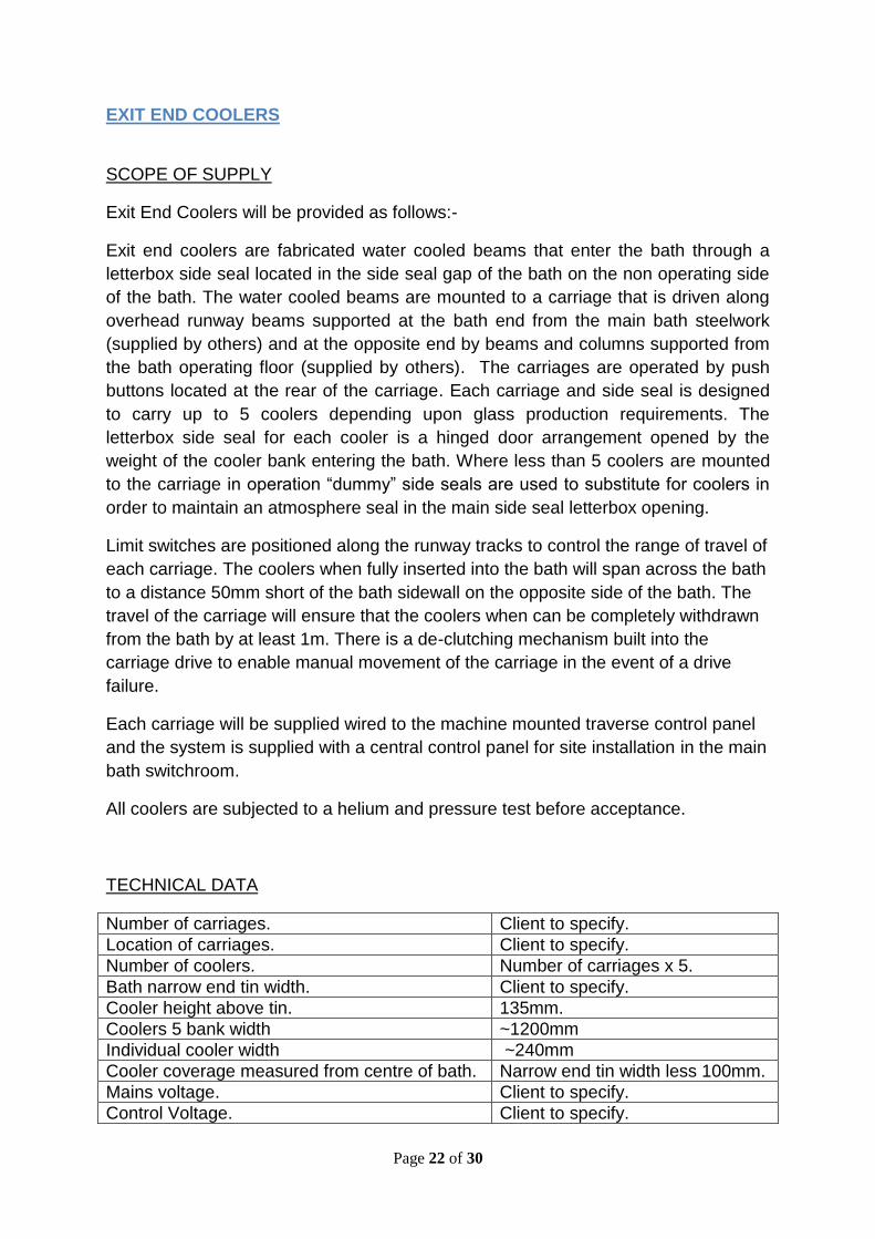
Exit end coolers are fabricated water cooled beams that enter the bath through a
letterbox side seal located in the side seal gap of the bath on the non operating side
of the bath. The water cooled beams are mounted to a carriage that is driven along
overhead runway beams supported at the bath end from the main bath steelwork
(supplied by others) and at the opposite end by beams and columns supported from
the bath operating floor (supplied by others). The carriages are operated by push
buttons located at the rear of the carriage. Each carriage and side seal is designed
to carry up to 5 coolers depending upon glass production requirements. The
letterbox side seal for each cooler is a hinged door arrangement opened by the
weight of the cooler bank entering the bath. Where less than 5 coolers are mounted
to the carriage in operation “dummy” side seals are used to substitute for coolers in
order to maintain an atmosphere seal in the main side seal letterbox opening.
Limit switches are positioned along the runway tracks to control the range of travel of
each carriage. The coolers when fully inserted into the bath will span across the bath
to a distance 50mm short of the bath sidewall on the opposite side of the bath. The
travel of the carriage will ensure that the coolers when can be completely withdrawn
from the bath by at least 1m. There is a de-clutching mechanism built into the
carriage drive to enable manual movement of the carriage in the event of a drive
failure.
Each carriage will be supplied wired to the machine mounted traverse control panel
and the system is supplied with a central control panel for site installation in the main
bath switchroom.
All coolers are subjected to a helium and pressure test before acceptance.
TECHNICAL DATA
Number of carriages. Client to specify.
Location of carriages. Client to specify.
Number of coolers. Number of carriages x 5.
Bath narrow end tin width. Client to specify.
Cooler height above tin. 135mm.
Coolers 5 bank width ~1200mm
Individual cooler width ~240mm
Cooler coverage measured from centre of bath. Narrow end tin width less 100mm.
Mains voltage. Client to specify.
Control Voltage. Client to specify.

Page 23 of 30
EXCLUSIONS
The following are not included as part of the Exit End Cooler supply:-
Main supporting steelwork.
On site wiring to/from main control panel.
INFORMATION REQUIRED
In addition to the information listed above in Technical Data, see section at end of
document for drawings and other information required to be provided to Orwell
Engineering Solutions Ltd to enable manufacture of the exit end coolers to
commence.
LINEAR MOTORS & CARRIAGES
SCOPE OF SUPPLY
Linear motors are used in the bath as and when required during glass production to
generate tin flows by means of generating a magnetic field. They are also in
permanent use located in the de drossing pocket where they are used to draw dross
which gathers around the exit lip plate into the pocket where it is collected and can
be removed from the bath. Linear motors for general bath use are mounted on
carriages and inserted into the bath at a position to suit production needs through a
linear motor side seal. The de drossing linear motors are located permanently in the
de drossing pockets at the exit end of the bath, they are inserted through a special
side seal in the de drosing pocket (supplied by others) and the linear motor rests on
rebates in the refractory blocks in the pocket with the part of the linear motor beam
outside of the pocket supported by a stand resting on the bath house floor. The
linear motor carriages come with an in built transformer for low voltage supply to
operate the linear motor and include a low flow alarm panel as part of the carriage.
For the de drossing pocket linear motors separate stand alone transformers, flow
alarm panels and support stands are provided.
The supply includes 6 local control panels (one of which switches between a
carriage and the de drossing linear motors) and one main central control panel.
The Linear Motor heads and beams are subjected to a helium and pressure test
before acceptance.

Page 24 of 30
Linear Motors and Carriages will be provided as follows:-
3 Pair (6) Linear Motor Carriages.
2 Pair (4) 12 Pole Linear Motors.
2 Pair (4) 6 Pole Linear Motors.
3 De drossing linear motors 6 Pole (includes 1 spare).
TECHNICAL DATA
Overall length of 12 pole linear motor. ~5335mm.
Length of refractory head of 12 pole linear motor. 1270mm.
Overall length of 6 pole linear motor. ~4735mm.
Length of refractory head of 6 pole linear motor. 670mm.
Overall length of 6 pole de drossing linear motor. ~2650mm.
Length of refractory head of de drossing linear motor.
670mm.
Mains voltage. Client to specify.
Control Voltage. Client to specify.
EXCLUSIONS
The following are not included as part of the Linear Motor and Carriage supply:-
Main control panel installation and on site wiring to/from panel.
On site wiring to flow alarms.
INFORMATION REQUIRED
In addition to the information listed above in Technical Data, see section at end of
document for drawings and other information required to be provided to Orwell
Engineering Solutions Ltd to enable manufacture of the linear motors and carriages
to commence.
Page 25 of 30
TOP ROLL MACHINES
SCOPE OF SUPPLY
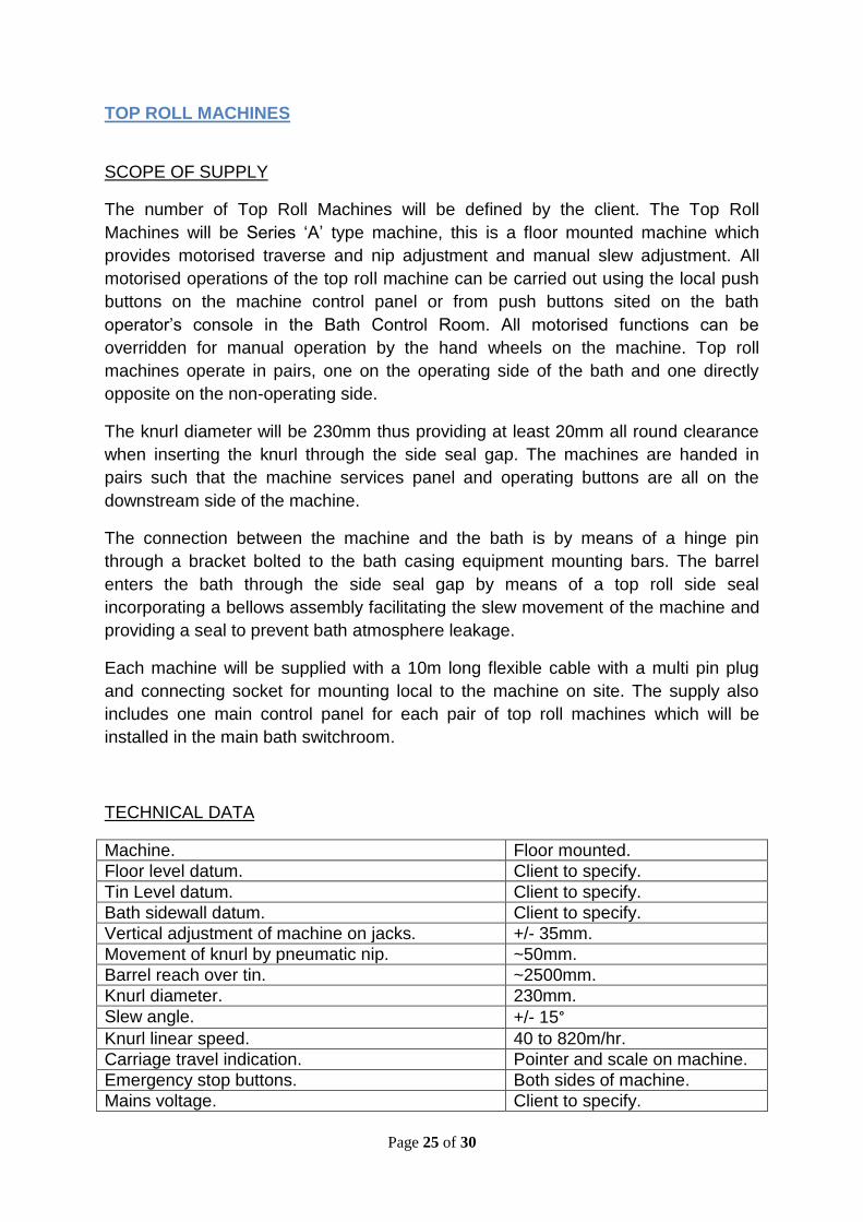
The number of Top Roll Machines will be defined by the client. The Top Roll
Machines will be Series ‘A’ type machine, this is a floor mounted machine which
provides motorised traverse and nip adjustment and manual slew adjustment. All
motorised operations of the top roll machine can be carried out using the local push
buttons on the machine control panel or from push buttons sited on the bath
operator’s console in the Bath Control Room. All motorised functions can be
overridden for manual operation by the hand wheels on the machine. Top roll
machines operate in pairs, one on the operating side of the bath and one directly
opposite on the non-operating side.
The knurl diameter will be 230mm thus providing at least 20mm all round clearance
when inserting the knurl through the side seal gap. The machines are handed in
pairs such that the machine services panel and operating buttons are all on the
downstream side of the machine.
The connection between the machine and the bath is by means of a hinge pin
through a bracket bolted to the bath casing equipment mounting bars. The barrel
enters the bath through the side seal gap by means of a top roll side seal
incorporating a bellows assembly facilitating the slew movement of the machine and
providing a seal to prevent bath atmosphere leakage.
Each machine will be supplied with a 10m long flexible cable with a multi pin plug
and connecting socket for mounting local to the machine on site. The supply also
includes one main control panel for each pair of top roll machines which will be
installed in the main bath switchroom.
TECHNICAL DATA
Machine. Floor mounted.
Floor level datum. Client to specify.
Tin Level datum. Client to specify.
Bath sidewall datum. Client to specify.
Vertical adjustment of machine on jacks. +/- 35mm.
Movement of knurl by pneumatic nip. ~50mm.
Barrel reach over tin. ~2500mm.
Knurl diameter. 230mm.
Slew angle. +/- 15° Knurl linear speed. 40 to 820m/hr.
Carriage travel indication. Pointer and scale on machine.
Emergency stop buttons. Both sides of machine.
Mains voltage. Client to specify.

Page 26 of 30
Control Voltage. Client to specify.
EXCLUSIONS
The following are not included as part of the top roll machine supply:-
Main control panels installation and on site wiring to/from panels.
On site wiring to local socket.
On site wiring to speed encoder.
Bath Control Room Function Buttons.
INFORMATION REQUIRED
In addition to the information listed above in Technical Data, see section at end of
document for drawings and other information required to be provided to Orwell
Engineering Solutions Ltd to enable manufacture of the top roll machines to
commence.
RIBBON EDGE BURNERS
SCOPE OF SUPPLY
Two manually adjustable ribbon edge burners on floor mounted trolleys will be
provided for use between the end of the dross box and the start of the lehr on either
side of the plant. The unit is a fabricated floor mounted trolley incorporating a
clamping plate on to which the ribbon edge burner can be mounted. The positioning
of the burner head relative to the ribbon edges is by manual adjustment of the burner
pipe by releasing the clamps and setting the pipe to the required position. The burner
pipe consists of a mixer unit and shut off valves, one end of the pipe is screwed to
the burner head.
TECHNICAL DATA
Drive. Air motor.
Burner Size. 10 inches (254mm).
Burner Construction. 3 slot head.
Cast Iron body.
Stainless steel flame posts.

Page 27 of 30
Burner Output. 44 Kw (max).
INFORMATION REQUIRED
See section at end of document for drawings and information required to be provided
to Orwell Engineering Solutions Ltd to enable manufacture of the ribbon edge
burners to commence.
BATH PERISCOPES
SCOPE OF SUPPLY
Periscopes for viewing equipment inside of the bath (i.e. top roll machines, pushers
etc) will be provided as specified by the client. The periscopes comprise an optical
tube with camera attached located inside a water cooled jacket fixed to a carriage
mounted to a track suspended from the side of the bath roof facilitating insertion and
removal from the bath. The camera projects a picture onto a monitor located in the
bath control room (supplied by others). Insertion of the periscope into the bath is
through a hole cut into the bath roof side wall which is sealed when the periscope is
not in use.
TECHNICAL DATA
Number of periscopes. Client to specify.
Reach into bath. ~ 3000mm
Viewing distance to object. Min 900mm – max 3500mm.
Camera. Hitachi.
Field of view. 36° +/- 2°. Operation. Manual.
EXCLUSIONS
The following are not included as part of the bath periscope supply:-
On site wiring of camera.
Bath control room monitors.
Local monitors (if being used).
Page 28 of 30
INFORMATION REQUIRED
In addition to the information listed above in Technical Data, see section at end of
document for drawings and other information required to be provided to Orwell
Engineering Solutions Ltd to enable manufacture of the bath periscopes to
commence.
BATH TV MONITORING SYSTEM
SCOPE OF SUPPLY
A television camera system for general viewing of the bath and glass ribbon will be
provided as follows:-
One pair of cameras to be positioned at the hot end to view inside of the bath looking
downstream through high level windows in the bath roof each side of the bath roof
lintel. This system is adjustable to enable the camera to swing on an arm and also
view through a high level window in the hot end taper section of the bath.
One pair of cameras to be positioned in the shoulder section each side of the bath
looking upstream through high level windows in the bath roof.
One pair of cameras at the exit end of the bath positioned each side of the line
between the sealed lehr and the front of the lehr to view the ribbon edges.
Each system is supplied complete with cameras, water cooled camera boxes and a
supporting steelwork structure.
The exit end camera system is also supplied with a floodlight to illuminate the area
being viewed.
EXCLUSIONS
The following are not included as part of the bath camera system supply:-
On site wiring of camera and floodlight (exit end cameras).
Bath control room monitors.
Local monitors (if being used).

Page 29 of 30
INFORMATION REQUIRED
See section at end of document for drawings and information required to be provided
to Orwell Engineering Solutions Ltd to enable manufacture of the bath periscopes to
commence.
INFORMATION REQUIRED BY ORWELL FROM CLIENT
In addition to the information indicated in the Technical Data tables for each piece of
equipment that the client will need to provide, the following additional information /
detail is also required from the client.
Information required by Orwell Sent / Received
Bath House Floor Level Datum.
Tin Level Datum.
Top of Bath Sidewall Datum.
Top of Exit Lip Plate Datum.
Centre Line of Lift Out Rollers Datum.
Dimension Exit Lip Plate to centre Line of 1st Lift out roller.
Dimension centre Line of 1st Lift out roller to centre Line of 2nd Lift out roller.
Dimension centre Line of 2nd Lift out roller to centre Line of 3rd Lift out roller.
Bath Length.
Bath wide end width.
Bath narrow end width.
Side seal gap.
Confirmation of operating side of bath.
Confirmation of lift out roller drive of plant.
Tweel centres (longitudinally).
Data sheet (dimensions of tin thermocouples.

Page 30 of 30
DRAWINGS REQUIRED BY ORWELL FROM CLIENT
Orwell Engineering Solutions require copies of or access to view the following
drawings in order to co-ordinate the above equipment with the float bath
construction.
Drawings required by Orwell Sent / Received
Arrangement and details of bath bottom basement area below canal. To co-ordinate tweel raising gear.
Details of bath supporting steelwork (Bays 1 and 2) – To co-ordinate hot end coolers.
Bath main column locations and sizes - To co-ordinate various pieces of equipment.
Details of bath supporting steelwork (narrow section) – To co-ordinate exit end coolers.
Bath casing details (1st casing – a wide section casing – shoulder section casing and last casing) – To co-ordinate various items of equipment.
Bath roof casing details (1st roof casing and shoulder casing) To co-ordinate high level window seals.
Bath roof casing details where periscopes are located.
Bath roof casing details where hot end coolers are located.
Last bath roof casing detail To co-ordinate sealed lehr.
Details of support steelwork below dross box.
Details of roof support steelwork above sealed lehr. To co-ordinate drape raise frame supports.
Arrangement of runway beams for lift out roller installation.
Lift out roller detail drawing – To co-ordinate dross box and roller bearings.
Arrangement of bath blocking – To co-ordinate tin thermocouple side seals and other equipment.
Detail of tin drain pockets and block. To determine tin pump.
Details of graphite barrier pieces.
Detail of 1st lehr section To co-ordinate lehr drape mechanism.