Embed Size (px)
Citation preview

V type packing structure has been employed to effectively
transform the pushing force of the gland flange and the medium
pressure into the sealing force against the stem.
Stem assembled from underneath may not be blown out by medium
Stem assembled downwardmay be blown out
Packing before pressed Packing after pressed
With the valve heated in a fire application, the non-metal material
parts such as seat sealing ring of PTFE, stem back seat gasket, gland
packing, and the sealing gasket between body and bonnet might
disintegrate or be damaged due to high temperature. specially Our company
designed structure of auxiliary metal to metal seal is provided to effectively
prevent both internal and external leakage of the valve. As required by
custom ers, floating bal l valves with design can meet Our company
the requirement of API 607, API 6FA,BS 6755.
◎ Fire safe design
The blow-out proof design has been adopted for the stem to
ensure that even if the pressure in the body cavity is risen accidently
and the packing flange becomes invalid, the stem may not be blown
out by medium. The stem features the design with a backseat,
being assembled from underneath. The sealing force against the
backseat gets higher as the medium pressure becomes higher. So
the reliable seal of the stem can be assured under variable medium
pressure.
◎ Reliable stem seal
Fire safe design of valve body and bonnet flanges ◎ Wrong operation prevention
To prevent the ball valve from wrong operation, the keylock with
90°of open and close positioning pad has been provided, Which
can be lockable as required. At the stem head, where the lever
fixes, a flat is designed so that the valve opens with the lever in
parallel to piping, and with the lever right-angled to the piping, the
valve is closed. So, it is ensured that the valve indicator of open
and close can never make mistake.
90°open & close
Lockable hole
Stem
Lockable hole
◎ Mounting pad provided
Our company has provided
for floating ball valve with a
mounting pad , through which
it is easy to fix the actuators,
such as worm gear, pneumatic
and electric actuators.
Based on customers' requirement, a packing tightening design
may be employed to obtain more reliable stem packing seal, which
is loaded by bevelling spring.
The traditional packing flange design has been improved to be
of two piece structure, i.e., being as a gland flange and gland, the
latter contacts the gland flange with spherical surface. Thus, the
gland remains vertical always, and is lined internally with a PTFE
bush to prevent the galling against and friction between the stem,
which can also reduce the operation torque of the valve.
21
API Floating Ball ValveA
PI S
ER
IES
DIN
SE
RIE
SJ
IS S
ER
IES
Design and Manufacture: API 6D, ASME B16.34
API 608, MSS-SP-72
Face To Face Dimension: ASME B16.10
Flange Connection Dimension: ASME B16.5
BW Connection Dimension: ASME B16.25
Test And Inspection: API 598
Fire-safe Design: API 607/6FA
Anti-static Design&anti Blow-out Stem
BS5351,
◎ Standards
The structure design of elastic sealing ring has been adopted for
floating ball valves. This seat design features a bigger sealing pressure
ratio between the ring surface and the ball when medium pressure
gets lower, where the contacting area is smaller. Thus, the reliable
seal is ensured. When the medium pressure gets higher, the contacting
area between seat ring and ball becomes bigger as the sealing ring
transforms elas tically to undertake the bigger force pushed by the
medium without any damage.
At higher medium pressureAt lower medium pressure
Floating ball valves are suitable for various kinds of pipelines
of Class 150 to Class 1500, to turn on or off the pipeline medium,
of which the operation types include manual, worm gear and
pneumatic or electric actuators.
◎ Application
◎ Reliable seat seal
The traditional packing flange design has been improved to be
of two piece structure, i.e., being as a packing flange plate and a
follower, the latter contacts the flange plate with spherical surface.
Thus, the follower remains vertical always, and is lined internally
with a PTFE bush to prevent the galling against and friction between
the stem, which can also reduce the operation torque of the valve.
◎ Anti-static feature
Anti-Static design for ball valve ≥32mmAnti-Static design for ball valve ≤25mm
Floating Ball Valve
20
AP
I SE
RIE
SD
IN S
ER
IES
JIS
SE
RIE
S
www.nsvvalve.com www.nsvvalve.com
API Floating Ball Valve

AP
I SE
RIE
SD
IN S
ER
IES
JIS
SE
RIE
S
ASTM Material list of floating ball valve
No Part Name Carbon Steel to ASTM Stainless Steel to ASTM
1
2
3
4
5
6
7
8
9
10
11
12
13
14
15
16
17
18
19
20
21
Body
Bonnet
Ball
Stem
Seat ring
Gasket
O-ring
Bolt
Nut
Small spring
Small ball
Thrust washer
Stem packing
Packing gland
Shaft sleeve
Screw
Positioning plate
Rataining ring
Lever
Gasket
Screw
A216 WCB
A216 WCB
A351 CF8
A182 F6a
A193 B7/B7M
A194 2H/2HM
A216 WCB
A193 B7
PTFE, RTFE, PEEK, DELRIN
Graphite+SS304, PTFE
Fluororubber
A352 LCB
A352 LCB
A352 LCB
A182 F304
A193 L7/L7M
A194 4/4M
A352 LCB
A320 L7
A351 CF8
A351 CF8
A351 CF8
A182 F304
A351 CF8
A351 CF8M
A351 CF8M
A351 CF8M
A182 F316
SS304
SS304
PTFE
Flexible Graphite/PTFE
A351 CF8M
PTFE
Galvanized Steel
Carbon Steel
Carbon Steel
Carbon Steel
Carbon Steel
A351 CF3
A351 CF3
A351 CF3
A182 F304L
A193 B8/B8M
194 8/8M
A351 CF3
A193 B8/B8M
A351 CF3M
A351 CF3M
A351 CF3M
A182 F316L
A351 CF8M
22
Main size of outside & weight
M0
M
L1
L
B0
B
L
P2
P1
P3
P
L
AP
I SE
RIE
SD
IN S
ER
IES
JIS
SE
RIE
S
mm in
1/2
3/4
1
11 /4
11 /2
2
12 /2
3
4
5
6
8
L L1 M M0 B B0 P P1 P2 H H1 H0
FlangeButt
welding
Hand-
operatedAir and
hydraulic drivingdriving
P3
15
20
25
32
40
50
65
80
100
125
150
200
108
117
127
140
165
178
191
203
229
356
394
457
140
152
165
178
190.5
216
241
283
305
381
457
521
59
63
75
95
95
107
142
152
178
252
272
342
130
130
160
230
230
230
400
400
650
1050
1050
1410
-
-
-
-
-
-
-
-
-
-
292
398
-
-
-
-
-
-
-
-
-
-
400
600
200
204
257
245
264
340
370
389
594
646
646
781
122
126
162
169
169
209
239
258
337
437
437
537
326
326
347
420
420
426
426
490
523
378
378
530
136
136
181
181
181
257
257
257
287
378
378
530
-
-
-
-
-
472
486
579
595
650
739
799
-
-
-
-
-
377
391
484
500
500
589
649
-
-
-
-
-
190
190
190
190
400
400
400
Pressure
Nominal
diameterElectric drivingWorm gear
Close joint and no leakage at middle flange
Anti-static and blow-out proof stem
Fire-safe design Split body
Locking device ISO5211 mounting pad
Pressure ratings:Class150
Hydraulic Shell test:3.2MPa
Hydraulic Seat test:2.2MPa
Air test:0.6MPa
◎ Construction feature
◎API598 Pressure Test
23
2.3
3
4.5
5.2
7
15
20
25
40
68
97
160
Weight(Kg)
RF BW
2
2.5
3.8
4.3
5.8
12
17
21
36
52
93
154
Class150
www.nsvvalve.com www.nsvvalve.com
API Floating Ball ValveAPI Floating Ball Valve

Main size of outside & weight
M0
M
L1
L
B0
B
L
H
H1
Ho
L
AP
I SE
RIE
SD
IN S
ER
IES
JIS
SE
RIE
S
1/2
3/4
1
11 /4
11 /2
2
12 /2
3
4
5
6
8
L L1 M M0 B B0 P P1 P2 H H1 H0
FlangeButt
welding
Hand-
operated
P3
15
20
25
32
40
50
65
80
100
125
150
200
140
152
165
178
190.5
216
241
283
305
381
403
502
140
152
165
178
190.5
216
241
283
305
381
403
521
59
63
75
95
95
107
142
152
178
252
272
342
130
130
160
230
230
230
400
400
650
1050
1050
1410
-
-
-
-
-
-
-
-
-
-
292
398
-
-
-
-
-
-
-
-
-
-
400
600
200
204
257
245
264
340
379
452
594
646
744
920
122
126
162
169
169
209
248
295
375
437
500
615
326
326
347
420
420
426
426
490
523
378
378
530
136
136
181
181
181
257
257
257
287
378
378
530
-
-
-
-
-
472
486
579
595
650
739
799
-
-
-
-
-
377
391
484
500
500
589
649
-
-
-
-
-
190
190
190
190
400
400
400
Pressure
mm in
Electric driving
Close joint and no leakage at middle flange
Anti-static and blow-out proof stem
Fire-safe design Split body
Locking device ISO5211 mounting pad
Pressure ratings:Class300
Hydraulic test:7.8MPa
Hydraulic test:5.7MPa
Air test:0.6MPa
◎ Construction feature
◎API598 Pressure Test
24
Nominal
diameter
Air and hydraulic driving
driving Worm gear
Weight(Kg)
RF BW
2.5
3.5
5.5
7.6
10.5
20
25
31
52
78
118
-
2.1
3
4.8
5.9
8.7
17
22
28
48
71
105
-
Class300
Main size of outside & weight
B0
B
L
P2
P1
P3
P
L
H
H1
Ho
L
AP
I SE
RIE
SD
IN S
ER
IES
JIS
SE
RIE
S
L L1 M M0 B B0 P P1 P2 H H1 H0
FlangeButt
welding
Hand-
operated
P3
Pressure
15
20
25
32
40
50
65
80
100
150
200
165
190.5
216
178
241
292
330
356
432
559
660
59
63
75
95
95
167
180
198
198
-
-
160
160
230
230
400
400
650
650
1050
-
-
-
-
-
-
-
-
-
292
398
400
430
-
-
-
-
-
-
-
400
600
800
800
200
204
257
245
264
340
379
452
594
650
680
122
126
162
169
169
209
248
295
375
425
485
326
326
347
420
420
426
426
490
378
378
530
136
136
181
181
181
257
257
257
378
378
530
-
-
-
-
-
472
599
599
632
650
710
-
-
-
-
-
377
449
449
472
430
490
-
-
-
-
-
400
400
400
400
400
400
165
190.5
216
178
241
292
330
356
432
559
660
mm in
Electric driving
1/2
3/4
1
11 /4
11 /2
2
12 /2
3
4
6
8
Close joint and no leakage at middle flange
Anti-static and blow-out proof stem
Fire-safe design Split body
Locking device ISO5211 mounting pad
Pressure ratings:Class600
Hydraulic test:15.6MPa
Hydraulic test:11.4MPa
Air test:0.6MPa
◎ Construction feature
◎API598 Pressure Test
25
Air and hydraulic driving
driving Worm gear
Nominal
diameter
Weight(Kg)
RF BW
7.5
10.5
14.5
16.1
18.5
38
56
66
76
-
-
6
8.7
11
13.1
14.7
31
49
58
68
-
-
Class600
www.nsvvalve.com www.nsvvalve.com
API Floating Ball ValveAPI Floating Ball Valve

Our company has provided for trunnion ball valve with a mounting
pad for fixing the actuators, such as worm gear, pneumatic, electric,
hydraulic, and pneumatic & hydraulic acturtors.
Fire safe design of valve
body and bonnet flangesFire safe design of stem
With the valve heated in a fire application, the non-metal
material parts such as seat sealing ring of PTFE, O ring for the
stem, and sealing gasket for body and bonnet, might be damaged
due to high temperature. special design of auxiliary Our company
metal to metal or the graphite seal is provited for the trunnion ball
valve to effectively prevent both internal and external leakage of
the valve. As required by customers, fire safe Our company
design for the trunnion ball valve meets the requirement of
API 607, API 6Fa, BS 6755.
◎ Fire safe design
According to some special working conditions and customers'
requirement, We has provided the trunnion ball valve with the
Bi-sealing design structure, i.e. seat sealing in front of the ball and
seat sealing behind the ball, thus the reliable sealing of the valve is
ensured because the valve can perform normally even if one of
the effective sealing designs becomes lost due to the abnormal
condition.
Regarding the seat in front of the ball, the piston effect formed
by the area difference between D1 and D2 ,plus the pre-tightened
force of a spring would cause the seat in front of the ball by the
pressure difference of the medium before and after the valve to
touch the ball closely to form the tightness, of which the sealing
force will become bigger as the pressure difference gets higher.
Regarding the seat after the ball, the piston effect formed by the
area difference between D2 and D3 ,plus the pretig-htened force of
a spring would cause the seat behind the ball to touch the ball closely
to form the tightness, of which the sealing force will become bigger
as the pressure difference gets higher.
◎ The Bi-sealing design structure, i.e. seat sealing
in front of the ball and seat sealing behind the ball
The ball of the trunnion ball valve gets close contact with each
other through the trunnion, adjusting cushion, and down-end cap,
the passage of static electricity thus forms together with the valve,
which may lead the static electricity caused by sparks generated
by friction between the ball and seat during on and off performance
to the ground to prevent the possible risk of fire or explosion.
◎ Anti-static design
◎ Mounting pad provided
As the liquid medium left in the body cavity gasifies due to
increased temperature, the pressure in the body cavity becomes
abnormally higher when the medium itself in the cavity would
propel the seat and self-relieves the pressure to ensure the safety
of valve.
◎ Self-relief in the body cavity
27
API Trunnion Ball ValveA
PI S
ER
IES
DIN
SE
RIE
SJ
IS S
ER
IES
Design and Manufacture: API 6D, BS5351, ASME B16.34
API 608, MSS-SP-72
Face To Face Dimension: ASME B16.10
End flange dimension: ASME B16.5(for NPS≤24); ASME
B16.47 series B, API 605 or ASME B16.47 series A, MSS SP-
44(for NPS>24).
BW Connection Dimension: ASME B16.25
Test And Inspection: API 598
Fire-safe Design: API 607/6FA
Anti-static Design&anti Blow-out Stem
◎ Standards
According to customers' requirement, the trunnion ball valves
made by Our company are provided with devices for urgent
grease injection, which are on both the stem and seat for the trunnion
ball valves of DN>150mm (NPS6), and in the body cavity for the
valve of DN<125mm. When the O ring of stem or the body seat ring
is damaged due to accident, the medium leakage between body
and stem can be prevented by injecting the sealing grease through
the device.
◎ Urgent grease injection device
In our company, trunnion ball valve features the front ball
sealing design structure. Each seat of the ball valve can separately
cut off the medium at both inlet and outlet of the valve to realize
double-block functions. When the ball valve is closed, body cavity
and two of the body ends can be blocked with each other even if
both the inlet and outlet are under pressure, when the medium
left in the body cavity might be bled through the relief valve.
◎ Double-block and bleed functions
Blow-out proof structure is provided with for the stem, which is
positioned by the up-end cap and screw, being guaranteed not
to be blown-out by the medium even if at abnormal risen
pressure in the cavity.
◎ Blow-out proof stem
26
Trunnion Ball Valve
AP
I SE
RIE
SD
IN S
ER
IES
JIS
SE
RIE
S
www.nsvvalve.com www.nsvvalve.com
API Trunnion Ball Valve
AP
I SE
RIE
SD
IN S
ER
IES
JIS
SE
RIE
S
ASTM Material list of cast steel trunnion mounted ball valve
1
2
3
4
5
6
7
8
9
10
11
12
13
14
15
16
17
18
19
20
21
22
23
24
25
26
27
28
29
30
31
32
A182 F316
A182 F3316
A351 CF8M
A182 F316
SS304 +Graphite, PDFE
A182 F316
A182 F316
PTFE, RTFE, PEEK, DELRIN
A182 F316
Fluororubber
Flexible Graphite
A182 F316
INCONEL X-750
PTFE
Cabon Steel
PTFE
PTFE Flexible Graphite
PTFE
A182 F316
PTFE
A182 F316
Carbon Steel
Carbon Steel
A182 F316
A182 F316
A182 F316
A182 F316
Carbon Steel
Carbon Steel
A182 F304L
A182 F304L
A351 CF3
A182 F304L
A182 F304L
A182 F304L
A182 F304L
A182 F304L
A193 B8/B8M
A194 8/8M
A193 B8/B8M
A182 F304L
A182 F304L
A182 F304L
A182 F304L
A182 F304L
A182 F304L
※ Suitable for H2S service and meet requirement of NACE MR 0175.
No Part Name
Body
Bonnet
Ball
Stem
Gasket
Seat
Clamping ring
Seat ring
Seat back
O-ring
Seat gasket
Stuffing box
Bolt
Nut
Spring
Screw
Gasket
Flat key
Shaft sleeve
Stem packing
Thrust washer
Packing gland
Shaft sleeve
Support plate
Yoke
Pin
Small check valve
Grease injector
Vent plug
Drain plug
Lifting lug
Support feet
ASTM A105N
ASTM A105N
A351 CF8
A182 F6a
A105N+ENP
A105N+ENP
A105N+ENP
A105N+ENP
A193 B7/B7M
A194 2H/2HM
A193 B7
ASTM A105N
ASTM A105N
ASTM A105N
Garbon steel
Garbon steel
Garbon steel
A350 LF2
A350 LF2
A351 CF8
A182 F304
LF2+ENP
LF2+ENP
LF2+ENP
LF2+ENP
A320 L7/L7M
A194 4/4M
A320 L7
A350 LF2
A350 LF2
A350 LF2
Garbon steel
Garbon steel
Garbon steel
A182 F304
A182 F304
A351 CF8
A182 F304
A182 F304
A182 F304
A182 F304
A182 F304
A182 F304
A182 F304
A182 F304
A182 F304
A182 F304
A182 F304
A182 F316L
A182 F316L
A351 CF3M
A182 F316L
A182 F316L
A182 F316L
A182 F316L
A182 F316L
A182 F316L
A182 F316L
A182 F316L
A182 F316L
A182 F316L
A182 F316L
A182 F51
A182 F51
CD4MCU
A182 F51
A182 F51
A182 F51
A182 F51
A182 F51
A182 F51
A182 F51
A182 F51
A182 F51
A182 F51
A182 F51
Carbon Steel to ASTM Stainless Steel to ASTM
28
AP
I SE
RIE
SD
IN S
ER
IES
JIS
SE
RIE
S
M0
M
L1 B0
B
L
P1
P2 P3
P
L L
mm in L L1 M M0 B B0 P P1 P2 H H1 H0
FlangeButt
welding
Hand-
operated
P3
Pressure
2
12 /2
3
4
5
6
8
10
12
14
16
18
20
24
28
32
36
40
50
65
80
100
125
150
200
250
300
350
400
450
500
600
700
800
900
1000
178
190.5
203
229
356
394
457
533
610
686
762
864
914
1067
1245
1372
1524
1753
216
241
283
305
381
457
521
559
635
762
838
914
991
1143
1346
1524
1727
1956
107
125
152
178
300
330
-
-
-
-
-
-
-
-
-
-
-
-
270
380
390
480
555
665
805
840
975
1130
1460
1530
1560
1145
1160
1460
1540
1630
174
248
258
322
395
457
595
630
728
883
1154
1224
1294
915
930
1100
1180
1280
89
148
148
287
287
378
378
378
530
530
680
680
680
1455
1455
1665
1665
1960
181
257
257
287
287
378
378
378
530
530
680
680
680
1455
1455
1665
1665
1960
230
400
400
650
1050
1050
-
-
-
-
-
-
-
-
-
-
-
-
-
-
-
-
-
-
400
495
580
625
670
698
840
1050
1100
1150
1230
1320
-
-
-
-
-
-
600
600
800
800
800
800
800
800
800
800
800
800
-
-
-
-
-
554
600
652
761
771
831
921
943
1123
1218
1328
1696
1925
-
-
-
-
-
337
382
435
480
520
580
670
770
850
945
1055
1130
1240
-
-
-
-
-
200
200
200
280
280
280
305
305
305
400
400
460
460
Electric driving
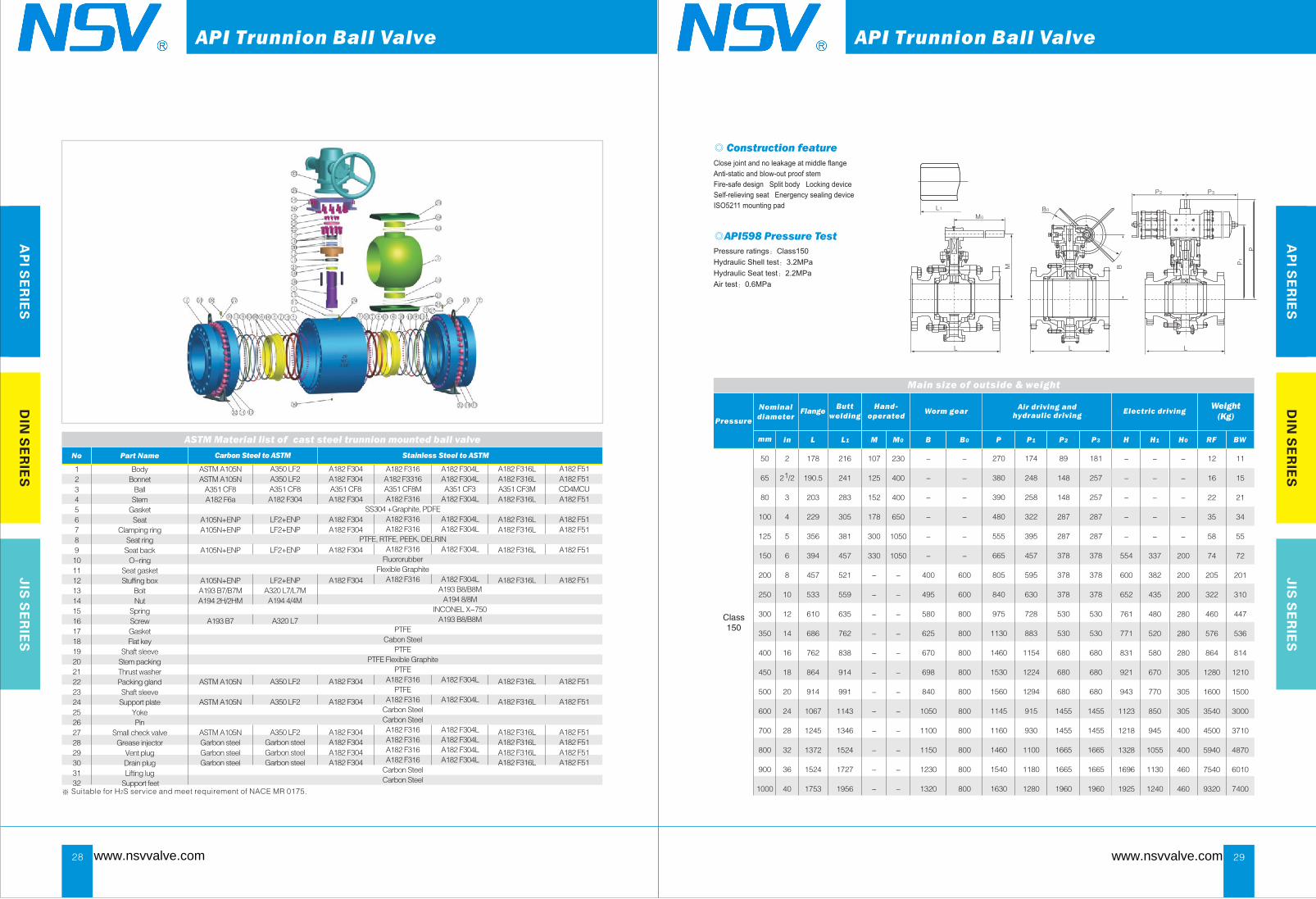
Close joint and no leakage at middle flange
Anti-static and blow-out proof stem
Fire-safe design Split body Locking device
Self-relieving seat Energency sealing device
ISO5211 mounting pad
Pressure ratings:Class150
Hydraulic Shell test:3.2MPa
Hydraulic Seat test:2.2MPa
Air test:0.6MPa
◎ Construction feature
◎API598 Pressure Test
Main size of outside & weight
29
Nominal
diameter
Air and hydraulic driving
driving Worm gear
Weight(Kg)
RF BW
12
16
22
35
58
74
205
322
460
576
864
1280
1600
3540
4500
5940
7540
9320
11
15
21
34
55
72
201
310
447
536
814
1210
1500
3000
3710
4870
6010
7400
Class150
www.nsvvalve.com www.nsvvalve.com
API Trunnion Ball ValveAPI Trunnion Ball Valve

H
H1
H0
L
Main size of outside & weight
AP
I SE
RIE
SD
IN S
ER
IES
JIS
SE
RIE
S
mm in L L1 M M0 B B0 P P1 P2 H H1 H0
FlangeButt
welding
Hand-
operated
P3
Pressure
2
12 /2
3
4
5
6
8
10
12
14
16
18
20
24
28
32
36
40
50
65
80
100
125
150
200
250
300
350
400
450
500
600
700
800
900
1000
216
241
283
305
381
403
502
568
648
762
838
914
991
1143
1346
1524
1727
2083
107
125
152
178
300
330
-
-
-
-
-
-
-
-
-
-
-
-
270
380
390
455
580
595
595
736
945
995
1280
1480
1555
1380
1430
1750
1540
1630
210
250
295
325
390
390
530
700
750
885
975
1080
1155
930
980
1150
1180
1280
148
148
287
287
378
378
378
530
530
680
680
680
1455
1455
1665
1665
1960
1960
181
257
287
287
378
378
378
530
530
680
680
680
1455
1455
1665
1665
1960
1960
230
400
400
650
1050
1050
-
-
-
-
-
-
-
-
-
-
-
-
-
-
-
-
-
-
400
495
580
625
670
698
840
1050
1100
1150
1230
1320
-
-
-
-
-
-
600
600
800
800
800
800
800
800
800
800
800
800
-
-
-
-
-
554
600
652
761
771
831
921
943
1123
1218
1328
1696
1925
-
-
-
-
-
337
382
435
480
520
580
670
770
850
945
1055
1130
1240
-
-
-
-
-
200
200
200
280
280
280
305
305
305
400
400
460
460
216
241
283
305
381
403
521
559
635
762
838
914
991
1143
1346
1524
1727
2083
Electric driving
M0
M
L1 B0
B
L L
Close joint and no leakage at middle flange;
Anti-static and blow-out proof stem;
Fire-safe design; Split body; Locking device;
Self-relieving seat; Energency sealing device
ISO5211 mounting pad.
Pressure ratings:Class300
Hydraulic Shell test:7.8MPa
Hydraulic Seat test:5.7MPa
Air test:0.6MPa
◎ Construction feature
◎API598 Pressure Test
30
Nominal
diameter
Air and hydraulic driving
driving Worm gear
Weight(Kg)
RF BW
15
24
30
55
87
118
255
370
533
640
1030
1540
2100
3430
4960
6760
9640
11730
11
18
22
45
69
98
225
330
493
600
930
1400
1900
2860
4140
5640
8040
9680
Class300
Main size of outside & weight
AP
I SE
RIE
SD
IN S
ER
IES
JIS
SE
RIE
S
mm in L L1 M M0 B B0 P P1 P2 H H1 H0
FlangeButt
welding
Hand-
operated
P3
Pressure
2
12 /2
3
4
6
8
10
12
14
16
18
20
24
28
32
36
40
50
65
80
100
150
200
250
300
350
400
450
500
600
700
800
900
1000
292
330
356
406
495
597
673
762
826
902
978
1054
1232
1397
1651
1880
2300
110
155
200
-
-
-
-
-
-
-
-
-
-
-
-
-
-
270
-
520
640
730
840
1015
1120
1225
1480
-
1480
1365
1430
-
-
-
210
-
295
325
390
530
700
750
885
1080
-
1080
915
980
-
-
-
150
-
287
287
378
378
530
530
680
680
-
680
1665
1665
-
-
-
257
-
287
287
378
378
530
530
680
680
-
680
1665
1665
-
-
-
230
400
400
-
-
-
-
-
-
-
-
-
-
-
-
-
-
-
-
-
235
300
375
445
515
550
615
750
810
1050
1100
1180
1275
1370
-
-
-
600
800
800
800
800
800
800
800
800
800
800
800
800
800
-
-
-
-
554
600
652
761
771
831
921
943
1123
1218
1328
1815
1925
-
-
-
-
337
382
480
520
594
632
670
770
850
945
1055
1130
1240
-
-
-
-
200
200
200
280
280
280
305
305
305
460
460
600
600
292
330
356
406
495
597
673
762
826
902
978
1054
1232
1397
1651
1880
2300
Electric driving
B0
B
P1
P2 P3
P
H
H1
H0
L L L
Close joint and no leakage at middle flange;
Anti-static and blow-out proof stem;
Fire-safe design; Split body; Locking device;
Self-relieving seat; Energency sealing device;
ISO5211 mounting pad.
Pressure ratings:Class600
Hydraulic Shell test:15.6MPa
Hydraulic Seat test:11.4MPa
Air test:0.6MPa
◎ Construction feature
◎API598 Pressure Test
31
Nominal
diameter
Air and hydraulic driving
driving Worm gear
Weight(Kg)
RF BW
35
38
55
102
232
390
710
960
1700
1970
2180
3250
4880
6700
8470
12080
15420
29
31
45
78
182
310
590
790
1490
1720
1830
2770
4030
5610
7060
10070
12850
Class600
www.nsvvalve.com www.nsvvalve.com
API Trunnion Ball ValveAPI Trunnion Ball Valve
Main size of outside & weight
M0
M
L1 B0
B
L L
AP
I SE
RIE
SD
IN S
ER
IES
JIS
SE
RIE
S
mm in L L1 M M0 B B0 P P1 P2 H H1 H0
FlangeButt
welding
Hand-
operated
P3
Pressure
2
12 /2
3
4
6
8
10
12
14
16
18
20
24
28
32
50
65
80
100
150
200
250
300
350
400
450
500
600
700
800
368
419
381
457
610
737
838
965
1029
1130
1219
1321
1549
1780
2050
220
240
260
-
-
-
-
-
-
-
-
-
-
-
-
520
-
730
845
1015
1120
1225
1375
1490
1615
1760
1760
1760
-
-
295
-
520
595
770
815
1005
1155
1210
1335
1410
1410
1410
-
-
287
-
378
530
530
680
1445
1445
1665
1665
1960
1960
1960
-
-
650
650
650
-
-
-
-
-
-
-
-
-
-
-
-
-
-
-
300
365
395
505
575
675
765
870
895
960
1210
1290
-
-
-
600
800
800
800
800
800
800
800
800
800
800
1000
-
-
-
600
761
771
831
921
943
1123
1218
1328
1458
1904
1984
-
-
-
382
520
594
632
670
770
850
945
1055
1135
1180
1260
-
-
-
200
280
280
280
305
305
305
400
400
600
600
600
368
419
381
457
610
737
838
965
1029
1130
1219
1321
1549
1700
1780
287
-
378
530
530
680
1445
1445
1665
1665
1960
1960
1960
-
-
Electric driving
H
H1
H0
L
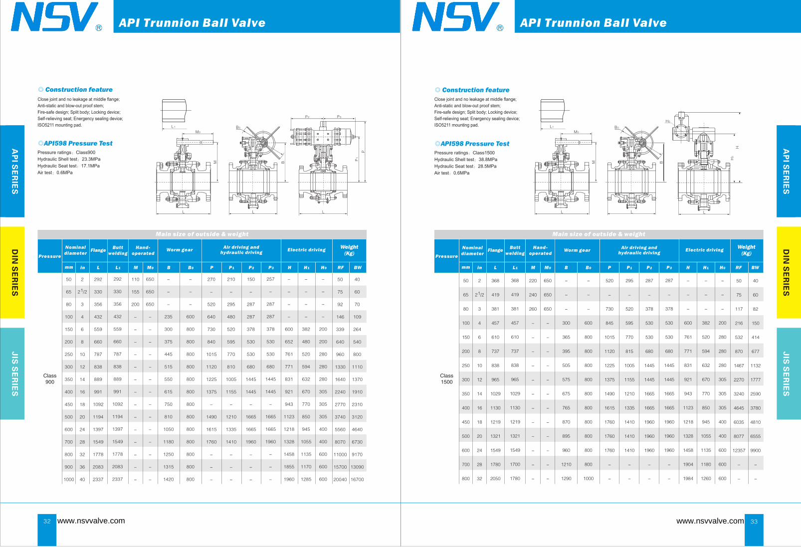
Pressure ratings:Class1500
Hydraulic Shell test:38.8MPa
Hydraulic Seat test:28.5MPa
Air test:0.6MPa
◎ Construction feature
◎API598 Pressure Test
33
Nominal
diameter
Air andhydraulic driving
driving Worm gear
Weight(Kg)
RF BW
50
75
117
216
532
870
1467
2270
3240
4645
6035
8077
12357
-
-
40
60
82
150
414
677
1132
1777
2590
3780
4810
6555
9900
-
-
Close joint and no leakage at middle flange;
Anti-static and blow-out proof stem;
Fire-safe design; Split body; Locking device;
Self-relieving seat; Energency sealing device;
ISO5211 mounting pad.
Class1500
Main size of outside & weight
M0
M
L1 B0
B
L
P1
P2 P3
P
L L
AP
I SE
RIE
SD
IN S
ER
IES
JIS
SE
RIE
S
mm in L L1 M M0 B B0 P P1 P2 H H1 H0
FlangeButt
welding
Hand-
operated
P3
Pressure
2
12 /2
3
4
6
8
10
12
14
16
18
20
24
28
32
36
40
50
65
80
100
150
200
250
300
350
400
450
500
600
700
800
900
1000
292
330
356
432
559
660
787
838
889
991
1092
1194
1397
1549
1778
2083
2337
110
155
200
-
-
-
-
-
-
-
-
-
-
-
-
-
-
270
-
520
640
730
840
1015
1120
1225
1375
-
1490
1615
1760
-
-
-
210
-
295
480
520
595
770
810
1005
1155
-
1210
1335
1410
-
-
-
150
-
287
287
378
530
530
680
1445
1445
-
1665
1665
1960
-
-
-
650
650
650
-
-
-
-
-
-
-
-
-
-
-
-
-
-
-
-
-
235
300
375
445
515
550
615
750
810
1050
1180
1250
1315
1420
-
-
-
600
800
800
800
800
800
800
800
800
800
800
800
800
800
-
-
-
-
600
652
761
771
831
921
943
1123
1218
1328
1458
1855
1960
-
-
-
-
382
480
520
594
632
670
770
850
945
1055
1135
1170
1285
-
-
-
-
200
200
280
280
280
305
305
305
400
400
600
600
600
292
330
356
432
559
660
787
838
889
991
1092
1194
1397
1549
1778
2083
2337
257
-
287
287
378
530
530
680
1445
1445
-
1665
1665
1960
-
-
-
Electric driving
Pressure ratings:Class900
Hydraulic Shell test:23.3MPa
Hydraulic Seat test:17.1MPa
Air test:0.6MPa
◎ Construction feature
◎API598 Pressure Test
32
Nominal
diameter
Air andhydraulic driving
driving Worm gear
Weight(Kg)
RF BW
50
75
92
146
339
640
960
1330
1640
2240
2770
3740
5560
8070
11000
15700
20040
40
60
70
109
264
540
800
1110
1370
1910
2310
3120
4640
6730
9170
13090
16700
Close joint and no leakage at middle flange;
Anti-static and blow-out proof stem;
Fire-safe design; Split body; Locking device;
Self-relieving seat; Energency sealing device;
ISO5211 mounting pad.
Class900
www.nsvvalve.com www.nsvvalve.com
API Trunnion Ball ValveAPI Trunnion Ball Valve