Embed Size (px)
Citation preview
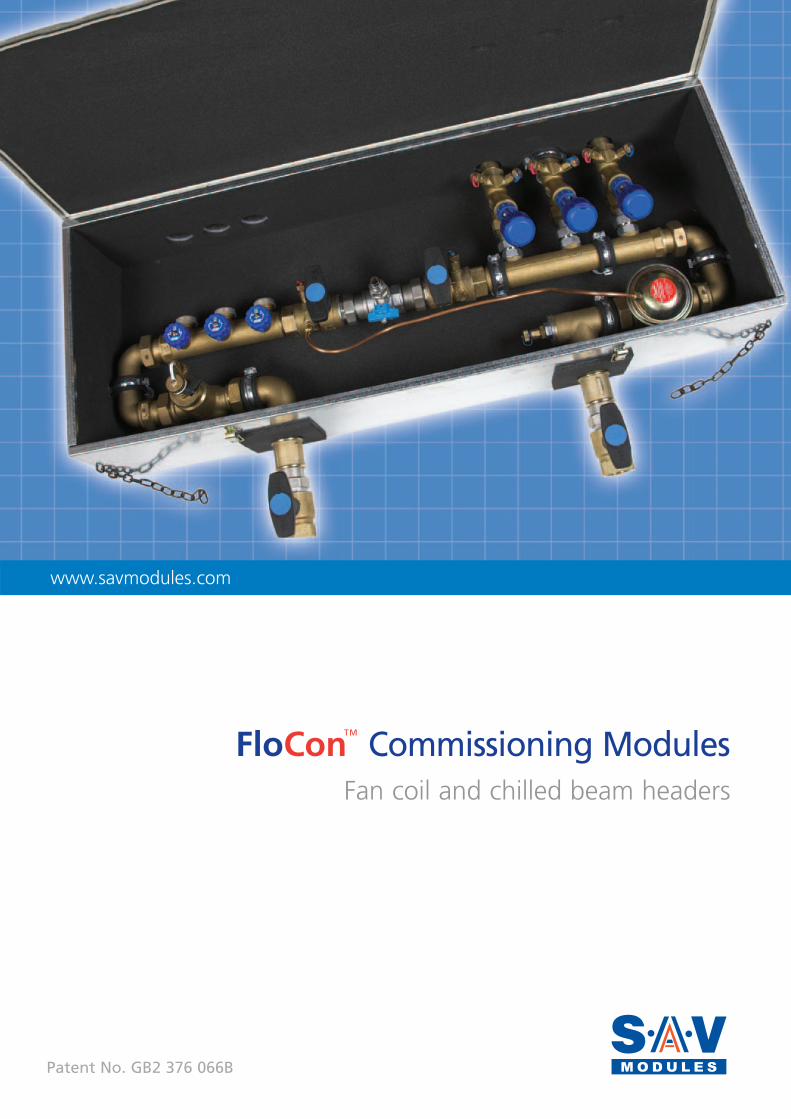
FloCon™ Commissioning ModulesFan coil and chilled beam headers
Patent No. GB2 376 066B
www.savmodules.com
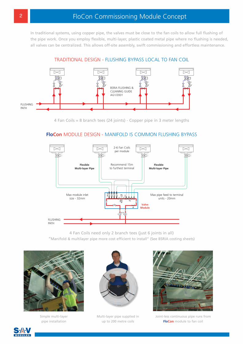
FloCon Commissioning Module Concept2
Valve Module
2-6 Fan Coils per module
Recommend 15m to furthest terminal
Max module inlet size - 32mm
Max pipe feed to terminal units - 20mm
Flexible Multi-layer Pipe
Flexible Multi-layer Pipe
FloCon MODULE DESIGN - MANIFOLD IS COMMON FLUSHING BYPASS
4 Fan Coils need only 2 branch tees (just 6 joints in all) “Manifold & multilayer pipe more cost efficient to install” (See BSRIA costing sheets)
4 Fan Coils = 8 branch tees (24 joints) - Copper pipe in 3 meter lengths
Multi-layer pipe supplied in
up to 200 metre coils
Simple multi-layer
pipe installation
Joint-less continuous pipe runs from
FloCon module to fan coil
BSRIA FLUSHING &CLEANING GUIDEAG1/2001
In traditional systems, using copper pipe, the valves must be close to the fan coils to allow full flushing of
the pipe work. Once you employ flexible, multi-layer, plastic coated metal pipe where no flushing is needed,
all valves can be centralized. This allows off-site assembly, swift commissioning and effortless maintenance.
TRADITIONAL DESIGN - FLUSHING BYPASS LOCAL TO FAN COIL
FLUSHING PATH
FLUSHING PATH
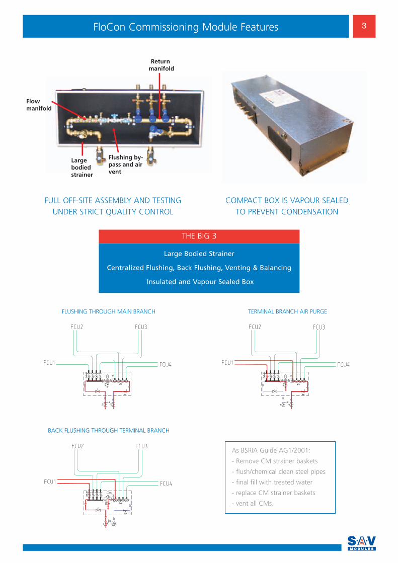
Largebodiedstrainer
Flowmanifold
Returnmanifold
Flushing by-pass and airvent
Large Bodied Strainer
Centralized Flushing, Back Flushing, Venting & Balancing
Insulated and Vapour Sealed Box
THE BIG 3
FULL OFF-SITE ASSEMBLY AND TESTINGUNDER STRICT QUALITY CONTROL
COMPACT BOX IS VAPOUR SEALED TO PREVENT CONDENSATION
As BSRIA Guide AG1/2001:
- Remove CM strainer baskets
- flush/chemical clean steel pipes
- final fill with treated water
- replace CM strainer baskets
- vent all CMs.
FLUSHING THROUGH MAIN BRANCH
BACK FLUSHING THROUGH TERMINAL BRANCH
TERMINAL BRANCH AIR PURGE
3FloCon Commissioning Module Features
Start
Finish
Step 1
Step 2
Step 3
Step 4
Step 4
Start
Step 1
Step 2
Finish
Step 3
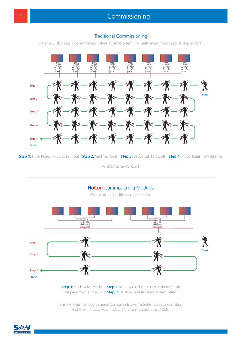
Traditional CommissioningExtremely laborious - decentralized valves at remote terminal units mean much use of stepladders!
Step 1: Flush Pipework up to Fan Coil Step 2: Vent Fan Coils Step 3: Back-Flush Fan Coils Step 4: Proportional Flow Balance
Step 1: Flush Valve Module Step 2: Vent, Back-Flush & Flow Balancing can be performed at one visit. Step 3: Balance modules against each other
4 Commissioning
As BSRIA Guide AG1/2001
As BSRIA Guide AG1/2001: Remove CM strainer baskets,flush/chemical clean steel pipes,
final fill with treated water, replace CM strainer baskets, vent all CMs.
FloCon Commissioning ModulesGrouping makes life so much easier.
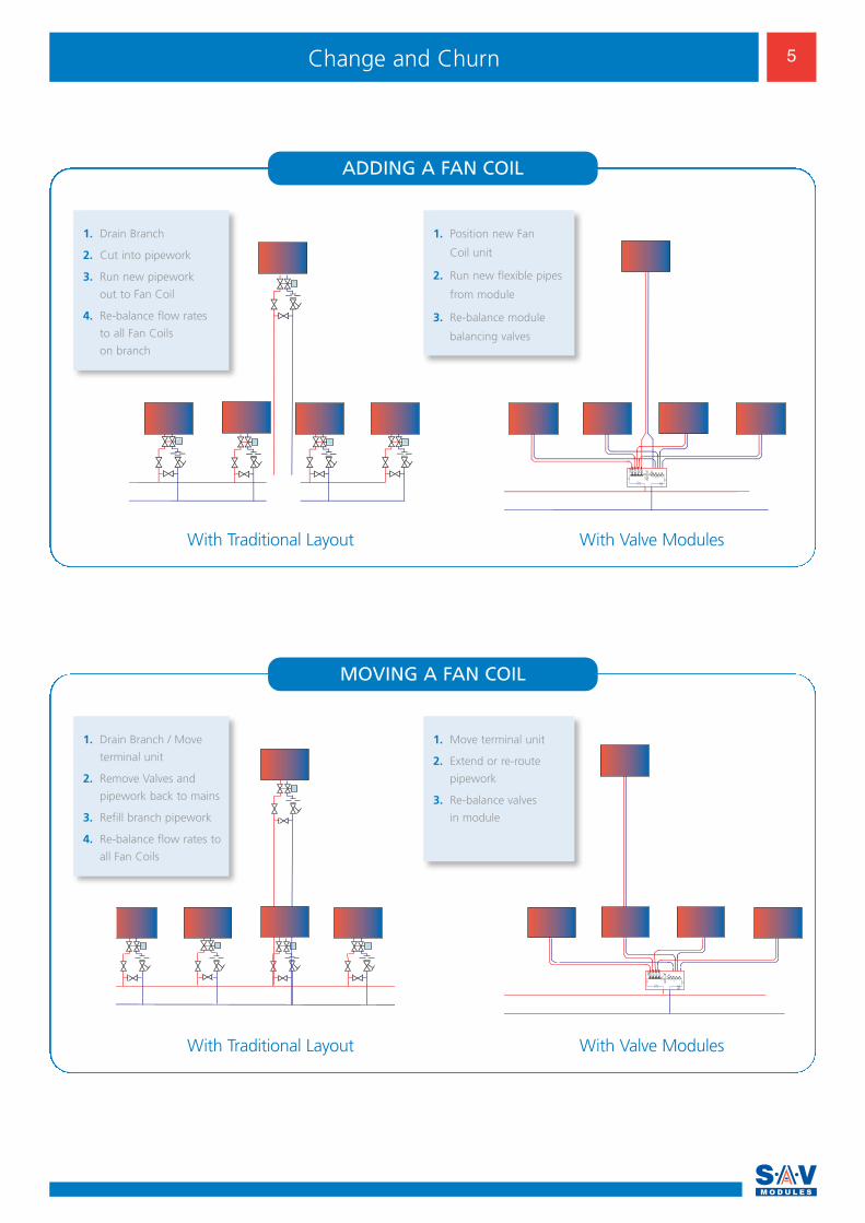
ADDING A FAN COIL
1. Drain Branch
2. Cut into pipework
3. Run new pipework
out to Fan Coil
4. Re-balance flow rates
to all Fan Coils
on branch
1. Position new Fan
Coil unit
2. Run new flexible pipes
from module
3. Re-balance module
balancing valves
With Valve ModulesWith Traditional Layout
MOVING A FAN COIL
With Valve ModulesWith Traditional Layout
1. Drain Branch / Move
terminal unit
2. Remove Valves and
pipework back to mains
3. Refill branch pipework
4. Re-balance flow rates to
all Fan Coils
1. Move terminal unit
2. Extend or re-route
pipework
3. Re-balance valves
in module
5Change and Churn
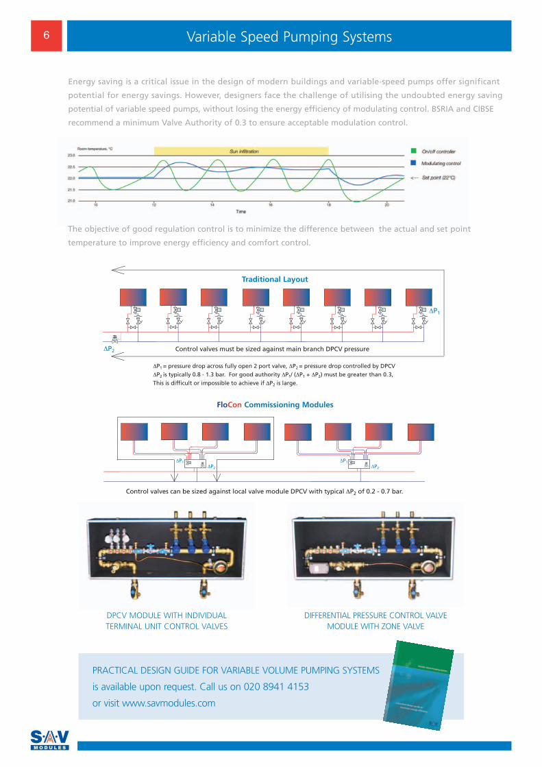
Control valves must be sized against main branch DPCV pressure
Control valves can be sized against local valve module DPCV with typical ΔP2 of 0.2 - 0.7 bar.
PRACTICAL DESIGN GUIDE FOR VARIABLE VOLUME PUMPING SYSTEMS
is available upon request. Call us on 020 8941 4153
or visit www.savmodules.com
DIFFERENTIAL PRESSURE CONTROL VALVE MODULE WITH ZONE VALVE
DPCV MODULE WITH INDIVIDUAL TERMINAL UNIT CONTROL VALVES
6 Variable Speed Pumping Systems
Energy saving is a critical issue in the design of modern buildings and variable-speed pumps offer significant
potential for energy savings. However, designers face the challenge of utilising the undoubted energy saving
potential of variable speed pumps, without losing the energy efficiency of modulating control. BSRIA and CIBSE
recommend a minimum Valve Authority of 0.3 to ensure acceptable modulation control.
The objective of good regulation control is to minimize the difference between the actual and set point
temperature to improve energy efficiency and comfort control.
Traditional Layout
FloCon Commissioning Modules
7Technical Data
2 pv Type - VZL2 DPCV - AVP-F
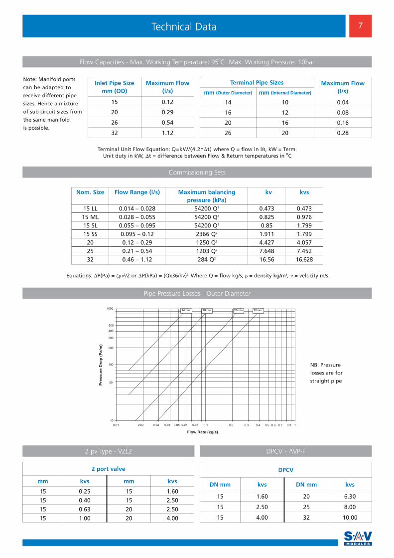
Flow Capacities - Max. Working Temperature: 95oC Max. Working Pressure: 10bar
Commissioning Sets
10
100
1000
0.01 0.1 1
Flow Rate (kg/s)
16mm
di
20mm
di
26mm
di
200
300
400
500
50
0.2 0.3 0.4 0.5 0.6 0.70.02 0.90.03 0.04 0.05 0.06 0.08
14mm
di
Pre
ss
ure
Dro
p (
Pa
/m)
Nom. Size Flow Range (l/s) Maximum balancing kv kvspressure (kPa)
15 LL 0.014 – 0.028 54200 Q2 0.473 0.47315 ML 0.028 – 0.055 54200 Q2 0.825 0.97615 SL 0.055 – 0.095 54200 Q2 0.85 1.79915 SS 0.095 – 0.12 2366 Q2 1.911 1.799
20 0.12 – 0.29 1250 Q2 4.427 4.05725 0.21 – 0.54 1203 Q2 7.648 7.45232 0.46 – 1.12 284 Q2 16.56 16.628
Equations: �P(Pa) = ���2/2 or �P(kPa) = (Qx36/kv)2 Where Q = flow kg/s, � = density kg/m3, � = velocity m/s
Terminal Unit Flow Equation: Q=kW/(4.2*�t) where Q = flow in l/s, kW = Term. Unit duty in kW, �t = difference between Flow & Return temperatures in oC
NB: Pressure
losses are for
straight pipe
Pipe Pressure Losses - Outer Diameter
Inlet Pipe Sizemm (OD)
Maximum Flow(l/s)
15 0.12
20 0.29
26 0.54
32 1.12
Terminal Pipe Sizes Maximum Flow(l/s)mm (Outer Diameter) mm (Internal Diameter)
14 10 0.04
16 12 0.08
20 16 0.16
26 20 0.28
Note: Manifold ports
can be adapted to
receive different pipe
sizes. Hence a mixture
of sub-circuit sizes from
the same manifold
is possible.
2 port valve
mm kvs mm kvs
15 0.25 15 1.60
15 0.40 15 2.50
15 0.63 20 2.50
15 1.00 20 4.00
DPCV
DN mm kvs DN mm kvs
15 1.60 20 6.30
15 2.50 25 8.00
15 4.00 32 10.00
UK Customer Support CentreSAV, Scandia House, 131 Armfield Close, West Molesey, Surrey KT8 2JR
Tel: +44 (0)20 8941 4153 Telefax: +44 (0)20 8783 1132 Email: [email protected] Web: www.savmodules.com
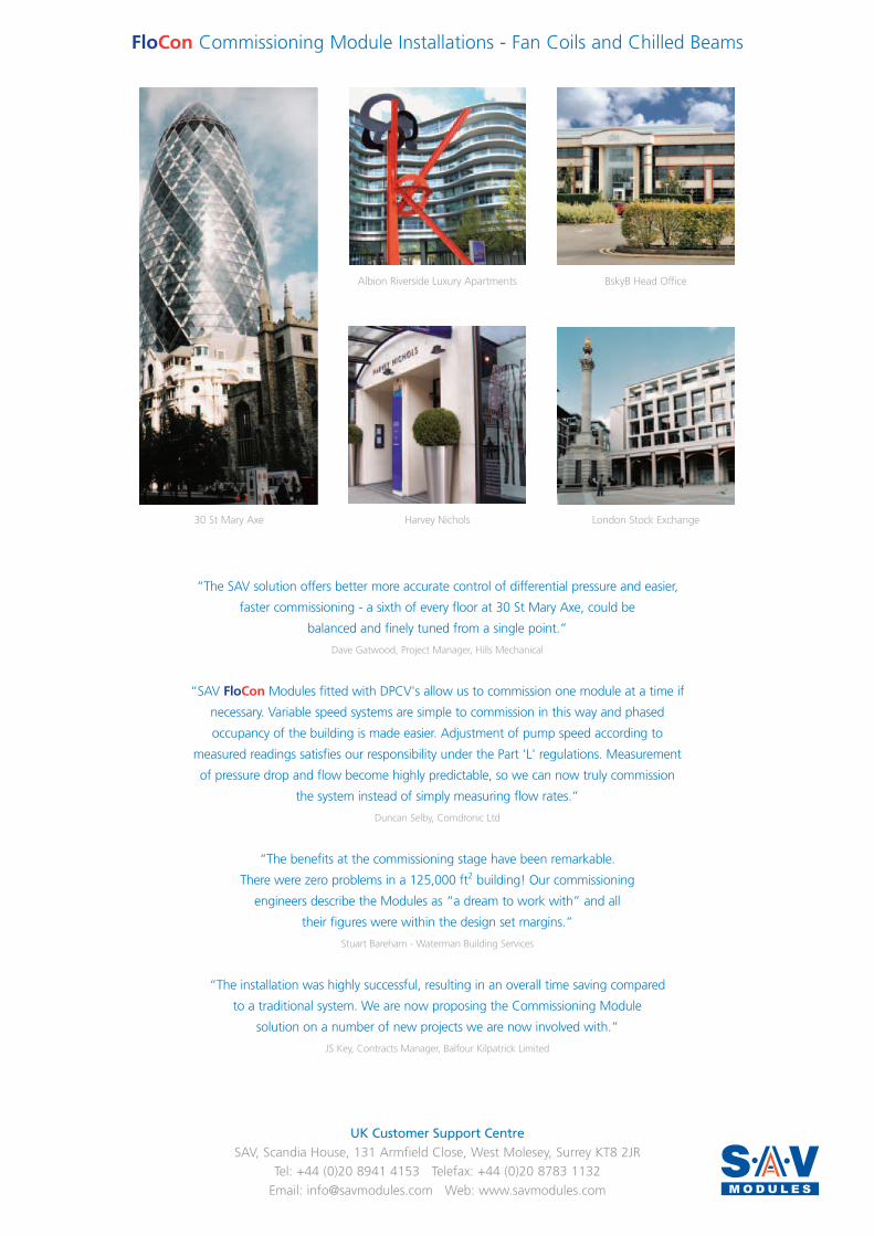
30 St Mary Axe
Albion Riverside Luxury Apartments BskyB Head Office
Harvey Nichols London Stock Exchange
“The SAV solution offers better more accurate control of differential pressure and easier,
faster commissioning - a sixth of every floor at 30 St Mary Axe, could be
balanced and finely tuned from a single point.”
Dave Gatwood, Project Manager, Hills Mechanical
“SAV FloCon Modules fitted with DPCV's allow us to commission one module at a time if
necessary. Variable speed systems are simple to commission in this way and phased
occupancy of the building is made easier. Adjustment of pump speed according to
measured readings satisfies our responsibility under the Part 'L' regulations. Measurement
of pressure drop and flow become highly predictable, so we can now truly commission
the system instead of simply measuring flow rates.”
Duncan Selby, Comdronic Ltd
“The benefits at the commissioning stage have been remarkable.
There were zero problems in a 125,000 ft2 building! Our commissioning
engineers describe the Modules as “a dream to work with” and all
their figures were within the design set margins.”
Stuart Bareham - Waterman Building Services
“The installation was highly successful, resulting in an overall time saving compared
to a traditional system. We are now proposing the Commissioning Module
solution on a number of new projects we are now involved with.”
JS Key, Contracts Manager, Balfour Kilpatrick Limited
FloCon Commissioning Module Installations - Fan Coils and Chilled Beams