Embed Size (px)
Citation preview
Floodproofing Non-Residential BuildingsFEMA P-936 / July 2013

FLOODPROOFING NON-RESIDENTIAL BUILDINGS i
Floodproofing Non-Residential BuildingsFEMA P-936 / July 2013

ii FLOODPROOFING NON-RESIDENTIAL BUILDINGS
All illustrations in this document were created by FEMA or a FEMA contractor unless otherwise noted.
All photographs in this document are public domain or taken by FEMA or a FEMA contractor, unless otherwise noted.
Questions or comments on this manual are welcome and should be addressed to FEMA Building Science (http://www.fema.gov/building-science) through the
FEMA Building Science Helpline at [email protected] or call (866) 927-2104.

FLOODPROOFING NON-RESIDENTIAL BUILDINGS iii
Acknowledgements
Acknowledgements
Authors and Key Contributors
David K. Low, P.E., DK Low and Associates
Amit Mahadevia, CFM, URS Group, Inc.
Manuel Perotin, P.E., CFM
Adam Reeder, P.E., CFM, Atkins Global
Adrienne Sheldon, P.E., CFM, URS Group, Inc.
Lauren Seelbach, E.I.T., CFM, URS Group, Inc.
Jennifer Sparenberg, CFM, URS Group, Inc.
John Squerciati, P.E., CFM, Dewberry
Reviewers and Contributors
Gene Barr, CFM, CH2M Hill, Inc.
Randy Behm, P.E., CFM, USACE, Omaha District
William Coulbourne, P.E., URS Group, Inc.
Jhun de la Cruz, FEMA Headquarters
Bret Gates, FEMA Headquarters
Michael Gease, FEMA Region VIII
Michael Grote, Gulf Coast Community Design Studio, Mississippi State University
Paul Gugenheim, Delta Structural Technologies
John Ingargiola, EI, CFM, CBO, FEMA Headquarters
Dick Jones, FEMA Region IV
Vasso Koumoudis, CFM, URS Group, Inc.
Stephen O’Leary, AIA, CFM, USACE, Huntington District

iv FLOODPROOFING NON-RESIDENTIAL BUILDINGS
A ACKNOWLEDGEMENTS
John “Bud” Plisich, FEMA Region IV
Rebecca Quinn, CFM, RCQuinn Consulting
Jody Springer, FEMA Headquarters
Alan Springett, FEMA Region II
Amy Tarce, AICP Assoc., AIA, National Capital Planning Commission
Paul Tertell, P.E., FEMA Headquarters (Retired)
Zachary Usher, FEMA Headquarters
Steven Van Dyke, FEMA Headquarters
Ronald Wanhanen, FEMA Region VI
Gregory Wilson, CFM, FEMA Headquarters
Wallace Wilson, P.E., CFM, URS Group, Inc.
Technical Editing, Layout, and Illustration
Diana Burke, ELS, URS Group, Inc.
Young Cho, URS Group, Inc.
Julie Liptak, Stantec
Lee-Ann Lyons, URS Group, Inc.
Ivy Porpotage, URS Group, Inc.
Billy Ruppert, URS Group, Inc.
Amy Siegel, URS Group, Inc.
Claude Tybaert, URS Group, Inc.
FLOODPROOFING NON-RESIDENTIAL BUILDINGS v
Table of Contents
1 Introduction ......................................................................................................... 1-1
1.1 Objective and Scope ...................................................................................................................1-1
1.2 Definitions and Key Concepts ....................................................................................................1-2
1.3 Limitations of Floodproofing and Precautionary Measures ..........................................................1-3
1.4 Assumptions ...............................................................................................................................1-4
1.5 Evaluation of Floodproofing Options .........................................................................................1-4
1.6 Icons ...........................................................................................................................................1-7
1.7 Organization ...............................................................................................................................1-8
2 Design Considerations in Floodproofing .............................................................. 2-1
2.1 Regulatory Requirements, Building Codes, Design Standards, and Guidance Documents .........2-2
2.1.1 National Flood Insurance Program ................................................................................. 2-2
2.1.2 Floodproofing Certificate for Non-Residential Buildings in Zone A ............................... 2-6
2.1.3 Floodproofing Historic Buildings .................................................................................. 2-7
2.1.4 National Policies for Federal Actions in Floodplains ....................................................... 2-8
2.1.5 Local Floodplain Management Regulations .................................................................. 2-10
2.1.6 Model Building Codes ................................................................................................. 2-10
2.1.7 Consensus Standards .................................................................................................... 2-13
2.1.8 Additional Federal Guidance Documents ..................................................................... 2-15
2.2 Design Loads and Site Characteristics .......................................................................................2-16
2.2.1 Identifying the Base Flood Elevation ............................................................................ 2-16
2.2.2 Design Flood Elevation ................................................................................................ 2-17
2.2.3 Determining the Flood Depth ...................................................................................... 2-18
2.2.4 Determining Hydrostatic Loads ................................................................................... 2-20
2.2.5 Determining Hydrodynamic Forces ............................................................................. 2-25
vi FLOODPROOFING NON-RESIDENTIAL BUILDINGS
TABLE OF CONTENTS
2.2.6 Determining Impact Loads .......................................................................................... 2-28
2.2.7 Interior Drain Systems ................................................................................................. 2-28
2.2.8 Determining Site Drainage for Floodwalls and Levees .................................................. 2-30
2.2.9 Understanding the All-Hazards Approach .................................................................... 2-33
2.3 Other Flood Characteristics .....................................................................................................2-34
2.3.1 Duration of Flooding ................................................................................................... 2-34
2.3.2 Rate of Floodwater Rise and Fall .................................................................................. 2-35
2.3.3 Flood Frequency ........................................................................................................... 2-35
2.3.4 Future Conditions ........................................................................................................ 2-36
2.4 Site Factors ...............................................................................................................................2-36
2.4.1 Flood Hazard Boundaries ............................................................................................. 2-36
2.4.2 Erosion ......................................................................................................................... 2-37
2.4.3 Geotechnical Considerations ........................................................................................ 2-38
2.5 Functional, Operational, and Economic Factors ......................................................................2-38
2.5.1 Functional Use Requirements of the Building .............................................................. 2-39
2.5.2 Occupant Safety ........................................................................................................... 2-39
2.5.3 Flood Warning Time .................................................................................................... 2-40
2.5.4 Flood Emergency Operations Plan ............................................................................... 2-41
2.5.5 Inspection and Maintenance Plan................................................................................. 2-42
2.5.6 Economic Factors ........................................................................................................ 2-43
2.6 Building Vulnerability Assessments ...........................................................................................2-43
2.6.1 All-Hazards Vulnerability Assessment ........................................................................... 2-44
2.6.2 Structural Condition Assessment ................................................................................. 2-44
2.6.3 Vulnerability Assessments for Electrical and Mechanical Utilities and Systems ............ 2-48
2.6.3.1 Utilities General ........................................................................................... 2-492.6.3.2 Electrical Utilities ......................................................................................... 2-492.6.3.3 Mechanical Utilities ...................................................................................... 2-502.6.3.4 Electrical Systems ......................................................................................... 2-502.6.3.5 Mechanical Systems ...................................................................................... 2-51
3 Dry Floodproofing Measures .............................................................................. 3-1
3.1 Design Considerations for Dry Floodproofing Project ................................................................3-2
3.1.1 Flood Warning Time ..................................................................................................... 3-2
FLOODPROOFING NON-RESIDENTIAL BUILDINGS vii
TABLE OF CONTENTS
3.1.2 Site and Building Evaluation .......................................................................................... 3-3
3.1.3 Building Standards and Codes ........................................................................................ 3-3
3.1.4 Verification and Testing of Systems ................................................................................. 3-5
3.2 Continuous Impermeable Walls ..................................................................................................3-5
3.2.1 Openings ....................................................................................................................... 3-6
3.2.2 Wall Systems .................................................................................................................. 3-7
3.3 Flood Resistance of Interior Core Areas ....................................................................................3-10
3.4 Shields for Openings .................................................................................................................3-11
3.4.1 Doors .......................................................................................................................... 3-12
3.4.2 Windows ...................................................................................................................... 3-12
3.4.3 Utility Connections ...................................................................................................... 3-13
3.5 Flood Shields for Openings in Exterior Walls ............................................................................3-14
3.5.1 Types of Flood Shields .................................................................................................. 3-14
3.5.2 Flood Shield Materials .................................................................................................. 3-18
3.5.3 Gaskets and Seals ......................................................................................................... 3-18
3.5.4 Plate-Style Flood Shields .............................................................................................. 3-19
3.5.5 Case Study: Retrofit Dry Floodproofed Building, New Castle, DE ............................... 3-22
3.6 Backflow Valves ........................................................................................................................3-24
3.7 Internal Drainage .....................................................................................................................3-27
3.7.1 Sump Pumps ................................................................................................................ 3-27
3.7.2 Pressure Relief Systems ................................................................................................. 3-32
3.8 Flood Emergency Operations Plan and Inspection and Maintenance Plan ...............................3-33
3.9 Dry Floodproofing in New Construction .................................................................................3-34
3.10 Case Study: University of Texas Perimeter Wall and Dry Floodproofing Project .......................3-38
4 Other Flood Protection Measures ......................................................................... 4-1
4.1 Floodwalls and Levees .................................................................................................................4-1
4.1.1 Floodwalls ...................................................................................................................... 4-1
4.1.1.1 Types of Floodwalls ........................................................................................ 4-2 4.1.1.1.1 Gravity Floodwalls .......................................................................................... 4-3 4.1.1.1.2 Cantilever Floodwalls ...................................................................... 4-4
viii FLOODPROOFING NON-RESIDENTIAL BUILDINGS
TABLE OF CONTENTS
4.1.1.1.3 Buttress and Counterfort Floodwalls................................................ 4-54.1.1.2 Building and Site Considerations in Floodwall Design ................................... 4-54.1.1.3 Floodwall Design Process ................................................................................ 4-8
4.1.2 Levees........................................................................................................................... 4-10
4.1.2.1 Building and Site Considerations in Levee Design ........................................ 4-104.1.2.2. Basic Levee Design Parameters ...................................................................... 4-114.1.2.3 Levee Design Process .................................................................................... 4-13
4.2 Wet Floodproofing Measures ....................................................................................................4-14
4.2.1 Flood Damage-Resistant Materials ............................................................................... 4-14
4.2.2 Protection of Vulnerable Equipment and Contents ..................................................... 4-16
4.2.3 Flood Openings for Equalization ................................................................................. 4-17
4.3 Floodproofing Electrical and Mechanical Utilities and Systems ................................................4-18
4.3.1 Electrical Utilities and Systems ..................................................................................... 4-21
4.3.2 Mechanical Utilities and Systems.................................................................................. 4-23
4.4 Emergency Measures .................................................................................................................4-24
4.4.1 Sandbags ...................................................................................................................... 4-24
4.4.2 Temporary Flood Barriers ............................................................................................. 4-25
4.4.3 Flood Wrapping Systems .............................................................................................. 4-26
4.5 Combination of Floodproofing Measures ..................................................................................4-29
4.5.1 Wet and Dry Floodproofing Techniques ....................................................................... 4-30
4.5.2 Other Combinations .................................................................................................... 4-32
4.5.3 Case Study: Application to Historic Buildings .............................................................. 4-32
Appendix A: FEMA Assistance
Appendix B: Understanding the FEMA Benefit-Cost Process
Appendix C: Checklist for Vulnerability of Flood-Prone Sites and Buildings
Appendix D: References
Appendix E: Resources
Appendix F: FEMA Region Contact Information
FLOODPROOFING NON-RESIDENTIAL BUILDINGS ix
TABLE OF CONTENTS
FiguresFigure 2-1 Satisfying NFIP requirements through building codes .................................................... 2-2
Figure 2-2 FEMA’s 8-step decision-making process for compliance with Executive Order (EO) 11998 and 44 CFR Part 9 ........................................................................... 2-9
Figure 2-3 Building and stream location on a FIRM .................................................................... 2-17
Figure 2-4 Flood depth .................................................................................................................. 2-20
Figure 2-5 Equal (A) and unequal (B) hydrostatic pressures applied to the exterior elements of a building; (B) shows the building protected by dry floodproofing methods applied ..................................................................................... 2-21
Figure 2-6 Hydrostatic forces acting on a foundation wall ............................................................. 2-24
Figure 2-7 Hydrodynamic and impact loads .................................................................................. 2-26
Figure 2-8 Frontal impact from debris ........................................................................................... 2-28
Figure 2-9 Typical interior drain systems ....................................................................................... 2-29
Figure 2-10 Rectangular area enclosed by a floodwall or levee.......................................................... 2-30
Figure 2-11 Rectangular area partially enclosed by a floodwall or levee ............................................ 2-32
Figure 2-12 Relationship between flood recurrence intervals and the probability of an event occurring within a given period ........................................................................... 2-36
Figure 2-13 Basic building components exposed to flood loads ....................................................... 2-45
Figure 2-14 Significant differential settlement in the foundation causing slab failure ....................... 2-47
Figure 2-15 Typical systems in buildings ......................................................................................... 2-49
Figure 3-1 Filled window opening ................................................................................................... 3-7
Figure 3-2 Application of a waterproof membrane on the exterior (positive side) of a wall (left) and fiber-reinforced polymer wrap applied to the interior (negative side) of a wall (right) ....................................................................................... 3-8
Figure 3-3 Decision process for selecting type of sealant .................................................................. 3-9
Figure 3-4 Interior drain in a dry floodproofed retail building ....................................................... 3-10
Figure 3-5 Watertight door used to protect mechanical rooms subject to flooding ......................... 3-11
Figure 3-6 Equipment room with watertight door ......................................................................... 3-12
Figure 3-7 Door opening protected from low-level flooding by a flood shield ................................ 3-14
Figure 3-8 Window protected from low-level flooding by a flood shield and wall sealant ............... 3-15
Figure 3-9 Aluminum flood shield used for flooding less than 3 feet deep ..................................... 3-15
Figure 3-10 Types of flood shields ................................................................................................... 3-17
x FLOODPROOFING NON-RESIDENTIAL BUILDINGS
TABLE OF CONTENTS
Figure 3-11 Selection/design of plate-style flood shields ................................................................. 3-19
Figure 3-12 Front of retrofit dry floodproofed building where drop-in flood shields protect doors ............................................................................................................... 3-23
Figure 3-13 Rear of retrofit dry floodproofed building with permanently installed flood shield ....... 3-23
Figure 3-14 Backflow valve ............................................................................................................. 3-24
Figure 3-15 Floor drain with a backflow valve with a ball float check valve ...................................... 3-25
Figure 3-16 Backflow valve selection process ................................................................................... 3-25
Figure 3-17 Typical sump detail ...................................................................................................... 3-27
Figure 3-18 Sump pump design process .......................................................................................... 3-30
Figure 3-19 A deteriorated flood shield gasket that must be replaced for the shield to seal and function properly ............................................................................................ 3-34
Figure 3-20 Dry floodproofed fuel pump room adjacent to generator fuel tank vault ..................... 3-35
Figure 3-21 Door to a dry floodproofed generator fuel tank vault servicing multiple generators in high-rise building ................................................................................... 3-36
Figure 3-22 Cross section of the test mock-up used for the SERRI tests of a substantially impermeable CMU wall system .............................................................. 3-37
Figure 3-23 Flood doors incorporated into the existing building façade .......................................... 3-39
Figure 3-24 Ross Sterling Avenue was raised to protect the MSB to the level of the base flood ....... 3-40
Figure 3-25 Three sets of stairs that provide building egress during the design flood event, but still allow normal use of the building .......................................................... 3-40
Figure 4-1 Typical masonry floodwall with engineered closures, which protected the Oak Grove Lutheran School in Fargo, ND, from flooding in 2001 ................................ 4-2
Figure 4-2 Gravity, cantilever, buttress, and counterfort floodwalls ................................................. 4-3
Figure 4-3 Concrete cantilever floodwall reinforcement .................................................................. 4-4
Figure 4-4 Stability of a cantilever floodwall ................................................................................... 4-5
Figure 4-5 Floodwall successfully safeguards Lourdes Hospital from Tropical Storm Lee flooding (source: FloodBreak) .................................................................................. 4-7
Figure 4-6 Aerial view showing effective protection of Lourdes Hospital from flooding as a result of Tropical Storm Lee ..................................................................................... 4-7
Figure 4-7 Floodwaters surround Columbus Regional Hospital in 2008 ......................................... 4-8
Figure 4-8 Columbus Regional Hospital schematic of floodwall plan .............................................. 4-8
Figure 4-9 Floodwall design process ............................................................................................... 4-9
Figure 4-10 Levee design parameters for a typical non-residential levee .......................................... 4-12
FLOODPROOFING NON-RESIDENTIAL BUILDINGS xi
TABLE OF CONTENTS
Figure 4-11 Basic levee design process ............................................................................................. 4-13
Figure 4-12 The Duval Beach Club after wet floodproofing retrofits ................................................ 4-16
Figure 4-13 Typical openings in walls of enclosures ......................................................................... 4-17
Figure 4-14 Non-residential structure retrofitted with flood openings following Hurricane Katrina (New Orleans, LA, 2008)................................................................ 4-18
Figure 4-15 Equipment in an electrical control panel that was mostly destroyed when approximately two-thirds of the height of panel was inundated by floodwaters (Columbus Junction, IA, 2008) ................................................................. 4-19
Figure 4-16 Main electrical service switchboard inundated by floodwaters that rose to the red mark on the doorframe (Cedar Rapids, IA, 2008) ............................................ 4-19
Figure 4-17 Undamaged secondary switchgear located at the University of Texas Medical Branch. The switchgear had been constructed on an upper floor that remained above flood levels. The switchgear was not damaged during Hurricane Ike (Galveston, TX, 2008) ........................................................................... 4-20
Figure 4-18 Emergency generator elevated above flood levels at the University of Texas Medical Branch, Hurricane Ike (Galveston, TX, 2008) ................................................ 4-20
Figure 4-19 Pad-mounted transformer and 15 kilovolt switchgear, both vulnerable to damage when inundated with floodwaters (Cedar Rapids, IA, 2008) ............................ 4-21
Figure 4-20 Electrical cables and an example of an electrical installation using cables ...................... 4-22
Figure 4-21 Example of installation using electrical conduits and insulated conductors .................. 4-22
Figure 4-22 Techniques for proper placement of sandbags .............................................................. 4-25
Figure 4-23 Three-foot-high water-filled temporary barrier protecting a structure in Tunica, MS .... 4-26
Figure 4-24 Gravel-filled containers that formed a barrier to protect the University of Iowa (2008) ................................................................................................................. 4-26
Figure 4-25 Plan view of wall section showing the deflection of a wrap at a doorway....................... 4-27
Figure 4-26 Plastic sheeting attached to a brick-faced wall to seal it from water intrusion ................ 4-27
Figure 4-27 Decision process for the selection and design of a flood wrapping system ..................... 4-28
Figure 4-28 Commercial structure in Darlington, WI mitigated using a combination of wet and dry floodproofing techniques .......................................................................... 4-30
Figure 4-29 A non-critical break room, originally located on an upper floor was relocated to create space for the critical control room ................................................... 4-31
Figure 4-30 Flooding of businesses in historic downtown Darlington, WI, Midwest Flood (1993).. 4-32
Figure 4-31 Businesses along Main Street in Darlington, WI, mitigated with an elevated interior first floor ............................................................................................ 4-33
xii FLOODPROOFING NON-RESIDENTIAL BUILDINGS
TABLE OF CONTENTS
Figure 4-32 Hardware store on Main Street in Darlington, WI, mitigated with a raised interior first floor and flood damage-resistant materials ................................................ 4-33
Figure 4-33 Hardware store on Main Street in Darlington, WI, showing ramp to elevated interior first floor for ADA compliance ........................................................... 4-33
TablesTable 1-1 Consideration of Floodproofing Measures for Non-Residential Buildings ...................... 1-5
Table 2-1 NFIP General Requirements for Dry Floodproofing ...................................................... 2-5
Table 2-2 NFIP General Requirements for Wet Floodproofing ..................................................... 2-6
Table 2-3 Key Code Requirements for Flood-Resistant Design from IBC 2012 ........................... 2-12
Table 2-4 ASCE 24 Requirements and Limitations for Dry Floodproofing .................................. 2-14
Table 2-5 ASCE 24 Requirements and Limitations for Wet Floodproofing .................................. 2-15
Table 2-6 Drag Coefficients for Ratios of Width to Depth (w/H) and Width to Height (w/h) ..... 2-28
Table 2-7 FEMA Resources on Design Guidance ......................................................................... 2-34
Table 3-1 Advantages and Disadvantages of Dry Floodproofing Retrofits Compared to Other Flood Mitigation Retrofit Measures ................................................................. 3-2
Table 3-2 ASCE 24 Structure Categories and Minimum Floodproofing Elevation in Zone A ........ 3-4
Table 3-3 Comparison of Types of Pump Activation Switches ...................................................... 3-29
Table 4-1 Class Descriptions of Flood Damage-Resistant Materials .............................................. 4-15
EquationsEquation 2-1 Flood depth .................................................................................................................. 2-19
Equation 2-2 Lateral hydrostatic forces .............................................................................................. 2-22
Equation 2-3 Submerged soil and water forces ................................................................................... 2-23
Equation 2-4 Buoyancy forces ........................................................................................................... 2-25
Equation 2-5 Hydrodynamic load ..................................................................................................... 2-27
Equation 2-6 Runoff quantity in an enclosed area .............................................................................. 2-31
Equation 2-7 Runoff quantitiy from higher ground into a partially enclosed area .............................. 2-32
Equation 2-8 Minimum discharge for pump installation ................................................................... 2-33
FLOODPROOFING NON-RESIDENTIAL BUILDINGS xiii
Acronyms and Abbreviations
AAA Aluminum Association
ACI American Concrete Institute
ADA Americans with Disabilities Act
AF&PA American Forest & Paper Association
AHPS Advanced Hydrology Prediction Service
AISC American Institute of Steel Construction
ANSI American National Standards Institute
ASCE American Society of Civil Engineers
ASD Allowable Stress Design
ASFPM Association of State Floodplain Managers
ASTM ASTM International
AWPA American Wood Protection Association
BBCA benefit-cost analysis
BCR benefit-cost ratio
BFE base flood elevation
CCFR Code of Federal Regulations
CMU concrete masonry unit
DDDF depth-damage function
DFA Damage Frequency Assessment
DFE design flood elevation

xiv FLOODPROOFING NON-RESIDENTIAL BUILDINGS
ACRONYMS AND ABBREVIATIONS
EEO Executive Order
FFEMA Federal Emergency Management Agency
FIRM Flood Insurance Rate Map
FIS Flood insurance Study
FMA Flood Mitigation Assistance
ft foot (feet)
ft/sec feet per second
Ggph gallons per hour
gpm gallons per minute
HH&H hydrologic and hydraulic
HMA Hazard Mitigation Assistance
HMGP Hazard Mitigation Grant Program
HVAC heating, ventilation, and air-conditioning
IIBC International Building Code
I-Codes International Code Series
ICC Increased Cost of Compliance
ICF Insulated Concrete Form
IEBC International Existing Building Code
in./hr inches per hour
IT information technology
Llb/ft2 pounds per square foot
lb/ft3 pounds per cubic foot
FLOODPROOFING NON-RESIDENTIAL BUILDINGS xv
ACRONYMS AND ABBREVIATIONS
lb/lf pounds per linear foot
LRFD Load Resistance Factored Design
MMEP mechanical, electrical, and plumbing
MSB Medical School Building
NNFIP National Flood Insurance Program
NFPA National Fire Protection Association
NWS National Weather Service
PPA Public Assistance
PDM Program Pre-Disaster Mitigation Program
RRisk MAP Risk Mapping, Assessment, and Planning
SSERRI Southeast Region Research Initiative
SFHA Special Flood Hazard Area
SIP Structural Insulated Panels
TTMS The Masonry Society
UUL Underwriters Laboratories
USACE U.S. Army Corps of Engineers
U.S.C. United States Code

FLOODPROOFING NON-RESIDENTIAL BUILDINGS 1-1
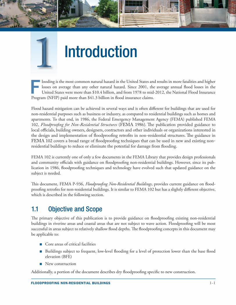
Introduction
F looding is the most common natural hazard in the United States and results in more fatalities and higher losses on average than any other natural hazard. Since 2001, the average annual flood losses in the United States were more than $10.4 billion, and from 1978 to mid-2012, the National Flood Insurance
Program (NFIP) paid more than $41.3 billion in flood insurance claims.
Flood hazard mitigation can be achieved in several ways and is often different for buildings that are used for non-residential purposes such as business or industry, as compared to residential buildings such as homes and apartments. To that end, in 1986, the Federal Emergency Management Agency (FEMA) published FEMA 102, Floodproofing for Non-Residential Structures (FEMA 1986). The publication provided guidance to local officials, building owners, designers, contractors and other individuals or organizations interested in the design and implementation of floodproofing retrofits in non-residential structures. The guidance in FEMA 102 covers a broad range of floodproofing techniques that can be used in new and existing non-residential buildings to reduce or eliminate the potential for damage from flooding.
FEMA 102 is currently one of only a few documents in the FEMA Library that provides design professionals and community officials with guidance on floodproofing non-residential buildings. However, since its pub-lication in 1986, floodproofing techniques and technology have evolved such that updated guidance on the subject is needed.
This document, FEMA P-936, Floodproofing Non-Residential Buildings, provides current guidance on flood-proofing retrofits for non-residential buildings. It is similar to FEMA 102 but has a slightly different objective, which is described in the following section.
1.1 Objective and ScopeThe primary objective of this publication is to provide guidance on floodproofing existing non-residential buildings in riverine areas and coastal areas that are not subject to wave action. Floodproofing will be most successful in areas subject to relatively shallow flood depths. The floodproofing concepts in this document may be applicable to:
■■ Core areas of critical facilities
■■ Buildings subject to frequent, low-level flooding for a level of protection lower than the base flood elevation (BFE)
■■ New construction
Additionally, a portion of the document describes dry floodproofing specific to new construction.
1-2 FLOODPROOFING NON-RESIDENTIAL BUILDINGS
1 INTRODUCTION
The publication focuses primarily on dry floodproofing but provides an overview of other retrofit methods that can be used in conjunction with or independent of dry floodproofing, including:
■■ Wet floodproofing
■■ Floodwalls
■■ Levees
■■ Protection of utilities
■■ Emergency floodproofing measures
The publication is intended to assist local government officials, engineers, architects, and property owners involved in the planning and implementation of floodproofing retrofits. Retrofits may be proposed voluntarily by the owner to reduce damage or may be necessary to meet building codes or floodplain management regula-tions. See Chapter 2 for information on floodplain management regulations related to the NFIP.
The following topics are not covered in detail:
■■ Residential construction, including large apartment and condominium complexes with multiple buildings, retirement homes, and nursing homes
■■ Operational considerations of floodproofing critical facilities
■■ Elevation
■■ Relocation
■■ Wave loads and Coastal A Zones
Building location, size, construction, function, and historic preservation factors dictate which floodproofing measure or measures will provide the most protection. The more complex the building, the more complex it is to protect. Combining methods of floodproofing is sometimes the best way to provide maximum protection (see Section 4.5).
1.2 Definitions and Key ConceptsFloodproofing is defined as any combination of structural or nonstructural adjustments, changes, or actions that reduce or eliminate flood damage to a building, contents, and attendant utilities and equipment (44 Code of Federal Regulations [CFR] §59.1 and American Society of Civil Engineers [ASCE] 24, Flood Resistant Design and Construction [2005]). Floodproofing can prevent damage to existing buildings and can be used to meet compliance requirements for new construction of non-residential buildings.
The concepts of the floodproofing measures used in this manual are defined as follows:
■■ Dry floodproofing. A combination of measures that results in a structure, including the attendant utilities and equipment, being watertight with all elements substantially impermeable to the entrance of floodwater and with structural components having the capacity to resist flood loads.
■■ Wet floodproofing. The use of flood-damage-resistant materials and construction techniques to minimize flood damage to areas below the flood protection level of a structure, which is intentionally allowed to flood.
FLOODPROOFING NON-RESIDENTIAL BUILDINGS 1-3
1INTRODUCTION
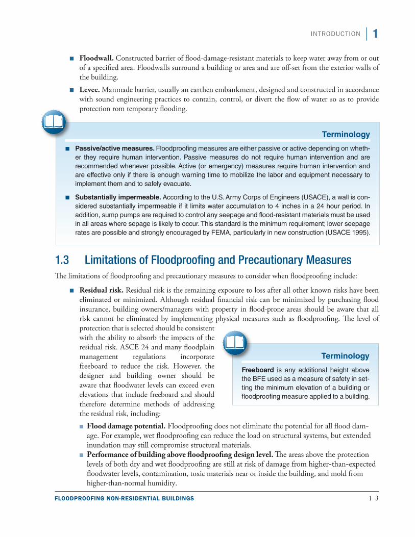
■■ Floodwall. Constructed barrier of flood-damage-resistant materials to keep water away from or out of a specified area. Floodwalls surround a building or area and are off-set from the exterior walls of the building.
■■ Levee. Manmade barrier, usually an earthen embankment, designed and constructed in accordance with sound engineering practices to contain, control, or divert the flow of water so as to provide protection rom temporary flooding.
1.3 Limitations of Floodproofing and Precautionary MeasuresThe limitations of floodproofing and precautionary measures to consider when floodproofing include:
■■ Residual risk. Residual risk is the remaining exposure to loss after all other known risks have been eliminated or minimized. Although residual financial risk can be minimized by purchasing flood insurance, building owners/managers with property in flood-prone areas should be aware that all risk cannot be eliminated by implementing physical measures such as floodproofing. The level of protection that is selected should be consistent with the ability to absorb the impacts of the residual risk. ASCE 24 and many floodplain management regulations incorporate freeboard to reduce the risk. However, the designer and building owner should be aware that floodwater levels can exceed even elevations that include freeboard and should therefore determine methods of addressing the residual risk, including:
■■ Flood damage potential. Floodproofing does not eliminate the potential for all flood dam-age. For example, wet floodproofing can reduce the load on structural systems, but extended inundation may still compromise structural materials.
■■ Performance of building above floodproofing design level. The areas above the protection levels of both dry and wet floodproofing are still at risk of damage from higher-than-expected floodwater levels, contamination, toxic materials near or inside the building, and mold from higher-than-normal humidity.
Terminology
■ Passive/active measures. Floodproofing measures are either passive or active depending on wheth-er they require human intervention. Passive measures do not require human intervention and are recommended whenever possible. Active (or emergency) measures require human intervention and are effective only if there is enough warning time to mobilize the labor and equipment necessary to implement them and to safely evacuate.
■ Substantially impermeable. According to the U.S. Army Corps of Engineers (USACE), a wall is con-sidered substantially impermeable if it limits water accumulation to 4 inches in a 24 hour period. In addition, sump pumps are required to control any seepage and flood-resistant materials must be used in all areas where sepage is likely to occur. This standard is the minimum requirement; lower seepage rates are possible and strongly encouraged by FEMA, particularly in new construction (USACE 1995).
Terminology
Freeboard is any additional height above the BFE used as a measure of safety in set-ting the minimum elevation of a building or floodproofing measure applied to a building.
1-4 FLOODPROOFING NON-RESIDENTIAL BUILDINGS
1 INTRODUCTION
■■ Space below the floodproofing design level. Floodproofing retrofits are implemented to prevent damage to existing buildings and are not intended to create usable space below the flood protection level.
■■ Occupation of floodproofed buildings. Floodproofed buildings are not meant to be occupied during a flood. Flood warning time should be adequate and evacuation plans should be developed to ensure that occupants are not stranded in the building during a flood. Dry floodproofing actually increases the risk to occupants if floodwaters rise higher than the floodproofing design level because severe structural damage can occur. Further, the interior of the building will likely be subject to inundation, which may occur rapidly.
1.4 AssumptionsThe guidance on floodproofing existing buildings in this publication is based on the following assumptions:
■■ The building does not have any unresolvable issues related to strength or materials that preclude dry floodproofing.
■■ Flood characteristics (e.g., depth, duration, velocity) on the building site are well defined and are reasonably predictable.
■■ Dry floodproofing is most likely to be successful for buildings subject to flooding depths, including freeboard, that do not exceed three feet, although it is recognized that floodproofing to a greater depth is feasible and may be appropriate, depending on the project.
■■ The building is in a riverine flood hazard area or in coastal areas subject to flood conditions without waves.
■■ Flood protection measures will be implemented to the flood protection level (or local regulatory flood elevation if compliance is required) not exceeding a height of three feet. FEMA strongly encourages flood retrofits to provide protection to the flood protection level or BFE plus one foot, whichever is higher, in accordance with International Building Code (IBC [2012]) and ASCE 24. Lower flood protection is sometimes appropriate, but the insurance implications should be considered. Building owners and design professionals should meet with a local building official to discuss the selected retrofit measure and the flood protection level.
All designs should be prepared or verified by a registered design professional before being implemented.
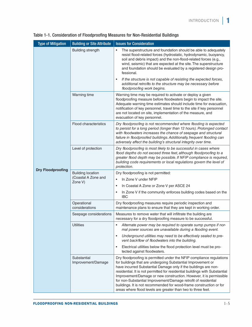
1.5 Evaluation of Floodproofing OptionsThe owner and designer should evaluate all possible methods of flood hazard mitigation before implement-ing mitigation options on a building. If relocating or elevating a building is not feasible or cost-effective, floodproofing may be an appropriate alternative. Table 1-1 presents important points to consider for various floodproofing measures, including dry floodproofing, wet floodproofing, floodwalls, and levees. These points of consideration are based either on established standards in ASCE 24, on regulatory documents, or on best practice guidance. Italic text indicates a consideration that is based on best practice guidance. The building and site characteristics may not be compatible with certain floodproofing measures, so the unique characteristics for each project should be taken into account.
FLOODPROOFING NON-RESIDENTIAL BUILDINGS 1-5
1INTRODUCTION
Table 1-1. Consideration of Floodproofing Measures for Non-Residential Buildings
Type of Mitigation Building or Site Attribute Issues for Consideration
Dry Floodproofing
Building strength ■• The superstructure and foundation should be able to adequately resist flood-related forces (hydrostatic, hydrodynamic, buoyancy, soil and debris impact) and the non-flood-related forces (e.g., wind, seismic) that are expected at the site. The superstructure and foundation should be evaluated by a registered design pro-fessional.
■• If the structure is not capable of resisting the expected forces, additional retrofits to the structure may be necessary before floodproofing work begins.
Warning time Warning time may be required to activate or deploy a given floodproofing measure before floodwaters begin to impact the site. Adequate warning time estimates should include time for evacuation, notification of key personnel, travel time to the site if key personnel are not located on site, implementation of the measure, and evacuation of key personnel.
Flood characteristics Dry floodproofing is not recommended where flooding is expected to persist for a long period (longer than 12 hours). Prolonged contact with floodwaters increases the chance of seepage and structural failure in floodproofed buildings. Additionally, frequent flooding can adversely affect the building’s structural integrity over time.
Level of protection Dry floodproofing is most likely to be successful in cases where flood depths do not exceed three feet, although floodproofing to a greater flood depth may be possible. If NFIP compliance is required, building code requirements or local regulations govern the level of protection.
Building location (Coastal A Zone and Zone V)
Dry floodproofing is not permitted:
■• In Zone V under NFIP
■• In Coastal A Zone or Zone V per ASCE 24
■• In Zone V if the community enforces building codes based on the IBC
Operational considerations
Dry floodproofing measures require periodic inspection and maintenance plans to ensure that they are kept in working order.
Seepage considerations Measures to remove water that will infiltrate the building are necessary for a dry floodproofing measure to be successful.
Utilities ■• Alternate power may be required to operate sump pumps if nor-mal power sources are unavailable during a flooding event.
■• Underground utilities may need to be effectively sealed to pre-vent backflow of floodwaters into the building.
■• Electrical utilities below the flood protection level must be pro-tected against floodwaters.
Substantial Improvement/Damage
Dry floodproofing is permitted under the NFIP compliance regulations for buildings that are undergoing Substantial Improvement or have incurred Substantial Damage only if the buildings are non-residential. It is not permitted for residential buildings with Substantial Improvement/Damage or new construction. However, it is permissible for non-Substantial Improvement/Damage retrofit of residential buildings. It is not recommended for wood-frame construction or for areas where flood levels are greater than two to three feet.
1-6 FLOODPROOFING NON-RESIDENTIAL BUILDINGS
1 INTRODUCTION
Type of Mitigation Building or Site Attribute Issues for Consideration
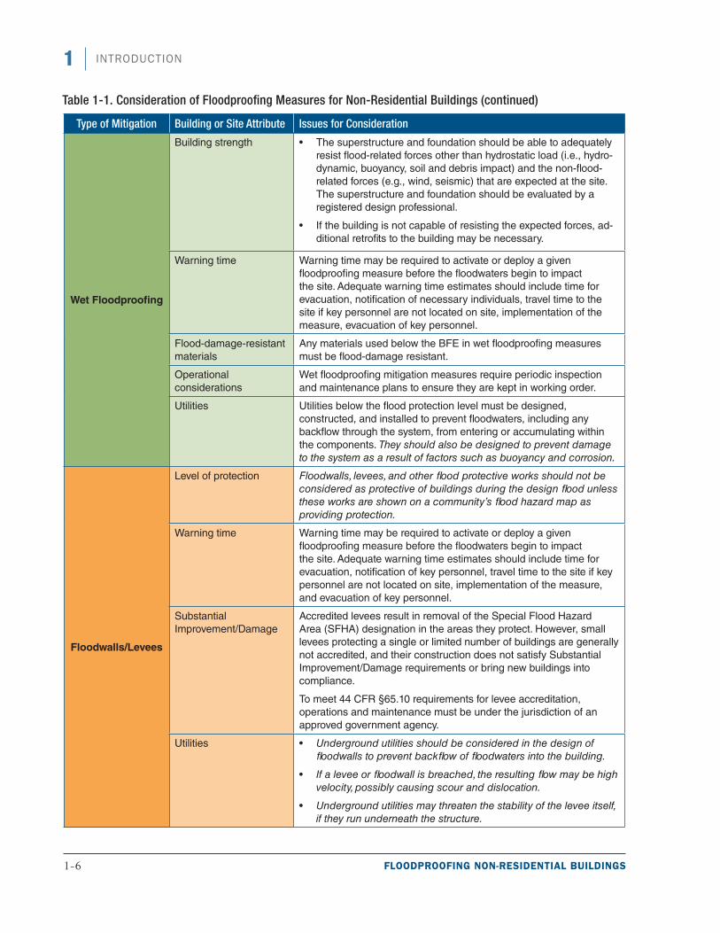
Wet Floodproofing
Building strength ■• The superstructure and foundation should be able to adequately resist flood-related forces other than hydrostatic load (i.e., hydro-dynamic, buoyancy, soil and debris impact) and the non-flood-related forces (e.g., wind, seismic) that are expected at the site. The superstructure and foundation should be evaluated by a registered design professional.
■• If the building is not capable of resisting the expected forces, ad-ditional retrofits to the building may be necessary.
Warning time Warning time may be required to activate or deploy a given floodproofing measure before the floodwaters begin to impact the site. Adequate warning time estimates should include time for evacuation, notification of necessary individuals, travel time to the site if key personnel are not located on site, implementation of the measure, evacuation of key personnel.
Flood-damage-resistant materials
Any materials used below the BFE in wet floodproofing measures must be flood-damage resistant.
Operational considerations
Wet floodproofing mitigation measures require periodic inspection and maintenance plans to ensure they are kept in working order.
Utilities Utilities below the flood protection level must be designed, constructed, and installed to prevent floodwaters, including any backflow through the system, from entering or accumulating within the components. They should also be designed to prevent damage to the system as a result of factors such as buoyancy and corrosion.
Floodwalls/Levees
Level of protection Floodwalls, levees, and other flood protective works should not be considered as protective of buildings during the design flood unless these works are shown on a community’s flood hazard map as providing protection.
Warning time Warning time may be required to activate or deploy a given floodproofing measure before the floodwaters begin to impact the site. Adequate warning time estimates should include time for evacuation, notification of key personnel, travel time to the site if key personnel are not located on site, implementation of the measure, and evacuation of key personnel.
Substantial Improvement/Damage
Accredited levees result in removal of the Special Flood Hazard Area (SFHA) designation in the areas they protect. However, small levees protecting a single or limited number of buildings are generally not accredited, and their construction does not satisfy Substantial Improvement/Damage requirements or bring new buildings into compliance.
To meet 44 CFR §65.10 requirements for levee accreditation, operations and maintenance must be under the jurisdiction of an approved government agency.
Utilities ■• Underground utilities should be considered in the design of floodwalls to prevent backflow of floodwaters into the building.
■• If a levee or floodwall is breached, the resulting flow may be high velocity, possibly causing scour and dislocation.
■• Underground utilities may threaten the stability of the levee itself, if they run underneath the structure.
Table 1-1. Consideration of Floodproofing Measures for Non-Residential Buildings (continued)
FLOODPROOFING NON-RESIDENTIAL BUILDINGS 1-7
1INTRODUCTION
Type of Mitigation Building or Site Attribute Issues for Consideration
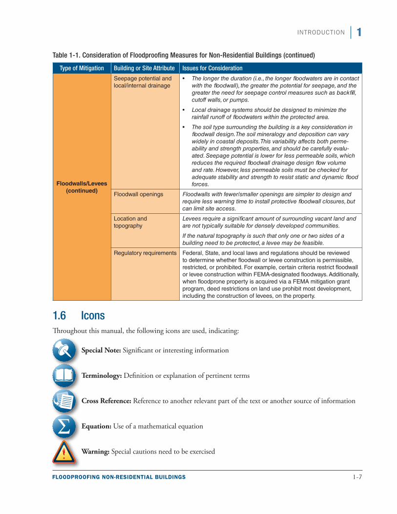
Floodwalls/Levees (continued)
Seepage potential and local/internal drainage
■• The longer the duration (i.e., the longer floodwaters are in contact with the floodwall), the greater the potential for seepage, and the greater the need for seepage control measures such as backfill, cutoff walls, or pumps.
■• Local drainage systems should be designed to minimize the rainfall runoff of floodwaters within the protected area.
■• The soil type surrounding the building is a key consideration in floodwall design. The soil mineralogy and deposition can vary widely in coastal deposits. This variability affects both perme-ability and strength properties, and should be carefully evalu-ated. Seepage potential is lower for less permeable soils, which reduces the required floodwall drainage design flow volume and rate. However, less permeable soils must be checked for adequate stability and strength to resist static and dynamic flood forces.
Floodwall openings Floodwalls with fewer/smaller openings are simpler to design and require less warning time to install protective floodwall closures, but can limit site access.
Location and topography
Levees require a significant amount of surrounding vacant land and are not typically suitable for densely developed communities.
If the natural topography is such that only one or two sides of a building need to be protected, a levee may be feasible.
Regulatory requirements Federal, State, and local laws and regulations should be reviewed to determine whether floodwall or levee construction is permissible, restricted, or prohibited. For example, certain criteria restrict floodwall or levee construction within FEMA-designated floodways. Additionally, when floodprone property is acquired via a FEMA mitigation grant program, deed restrictions on land use prohibit most development, including the construction of levees, on the property.
1.6 IconsThroughout this manual, the following icons are used, indicating:
Special Note: Significant or interesting information
Terminology: Definition or explanation of pertinent terms
Cross Reference: Reference to another relevant part of the text or another source of information
Equation: Use of a mathematical equation
Warning: Special cautions need to be exercised
Table 1-1. Consideration of Floodproofing Measures for Non-Residential Buildings (continued)

1-8 FLOODPROOFING NON-RESIDENTIAL BUILDINGS
1 INTRODUCTION
1.7 OrganizationThe information in this manual is organized as follows:
■■ Chapter 1: Introduction – Definition of floodproofing, limitations and assumptions in floodproofing non-residential buildings, and an evaluation of floodproofing measures.
■■ Chapter 2: Design Considerations for Floodproofing – Factors that influence the decision to implement a floodproofing measure.
■■ Chapter 3: Dry Floodproofing Measures – General design considerations for dry floodproofing, as well as a discussion of the types of dry floodproofing measures.
■■ Chapter 4: Other Floodproofing Measures – Floodwalls, levees; floodproofing utilities, wet floodproofing, and emergency floodproofing; pros and cons of each measure; other factors to consider when selecting a floodproofing measure; and how to combine floodproofing measures.
■■ Appendix A: FEMA Assistance – Overview of FEMA’s Hazard Mitigation Assistance grant programs.
■■ Appendix B: Understanding the FEMA Benefit-Cost Process – Importance of the Benefit-Cost Analysis (BCA) in FEMA assistance, data required to run a BCA module, and resources with additional information.
■■ Appendix C: Checklist for Vulnerability of Flood-prone Sites and Buildings – A tool that can be used to help assess site-specific flood hazards and building vulnerability.
■■ Appendix D: References – Cited references.
■■ Appendix E: Resources – Resources with additional information, including vulnerability and maintenance checklists.
■■ Appendix F: FEMA Region Contact Informattion – Mailing addresses and phone numbers for the FEMA Regions.
FLOODPROOFING NON-RESIDENTIAL BUILDINGS 2-1
T he most effective flood mitigation methods are relocation and elevation, but when these methods are not feasible or cost-effective, floodproofing may be an appropriate alternative. Some emergency mea-sures can be accomplished without expert construction assistance, and many can be used for low-level
or nuisance flooding while significantly reducing losses from these types of events.
The development of a floodproofing strategy should include considerations of a number of factors that will influence the design of the floodproofing measure or measures. This chapter contains a discussion of these fac-tors, which are:
■■ Design requirements. Regulatory requirements, building codes, design standards, and other guidance documents (Section 2.1)
■■ Design loads and site characteristics. Hydrostatic loads, hydrodynamic loads, wave loads, impact loads from flood-borne debris, internal drainage, and site drainage (Section 2.2)
■■ Flood characteristics. Flood elevations, duration of flooding, rate of floodwater rise and fall, flood frequency (Section 2.3)
■■ Site factors. Flood hazard boundaries, erosion and scour, and geotechnical considerations (Section 2.4)
■■ Functional, operational, and economic factors. Functional use requirements of the building, occupant safety, flood warning time, flood emergency operations plans, inspection and maintenance plans, and BCAs (Section 2.5)
■■ Vulnerability assessments. All-hazards vulnerability assessments, structural condition assessments of the building, and utility assessments (Section 2.6)
Design Considerations in Floodproofing
Cross Reference
Have questions about the NFIP?
See FEMA F-084, Answers to Questions about the NFIP (FEMA 2011b) at: http://www.fema.gov/media-library/assets/doc-uments/272. This document is intended to acquaint the public with the NFIP. It is designed for readers who do not need a detailed history or technical or legal explanations but who do need a basic understanding of the program and the answers to some frequently asked ques-tions. For legal definitions, see the NFIP Flood Insurance Manual (FEMA 2013), and National Flood Insurance Program Regulations (FEMA 2009a).
2-2 FLOODPROOFING NON-RESIDENTIAL BUILDINGS
2 DESIGN CONSIDERATIONS IN FLOODPROOFING
2.1 Regulatory Requirements, Building Codes, Design Standards, and Guidance Documents
Floodproofing may be proposed voluntarily by building owners or may be necessary to meet floodplain man-agement regulations or building codes. This section contains a discussion of the floodplain management regulations and building codes that can affect the type and design of floodproofing measures.
2.1.1 National Flood Insurance Program
Communities that participate in the NFIP are required to adopt and enforce local regulations for development in mapped Special Flood Hazard Areas (SFHAs) to reduce the risk of flooding (see 44 CFR Parts 59 and 60). However, communities are encouraged to adopt requirements that exceed Federal regulations. Homeowners, renters, and business owners, as well as communities that own buildings in participating communities are eli-gible for NFIP flood insurance coverage.
With the inclusion of NFIP-consistent provisions in the International Code Series (I-Codes), communi-ties that have adopted the I-Codes have two ways of enforcing NFIP flood-resistant design and con-struction requirements for buildings and structures:
■■ Using the I-Codes with NFIP-consistent provisions intact and IBC Appendix G; or
■■ Using the I-Codes with NFIP-consistent provisions intact and local floodplain management regulations that include requirements comparable to those in Appendix G.
These tools are designed to work together to result in buildings and structures, and all other development, that are resistant to flood loads and flood damage.
If a participating community has not adopted the I-Codes or if the NFIP-consistent provisions of the codes are not intact, the community must adopt local floodplain management regulations that include detailed and specific requirements for buildings and structures.
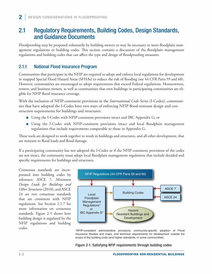
Consensus standards are incor-porated into building codes by reference; ASCE 7, Minimum Design Loads for Buildings and Other Structures (2010), and ASCE 24 are two consensus standards that are consistent with NFIP regulations. See Section 2.1.7 for more information on consensus standards. Figure 2-1 shows how building design is regulated by the NFIP regulations and building codes.
*NFIP-consistent administrative provisions, community-specific adoption of Flood Insurance Studies and maps, and technical requirements for development outside the scope of the building code (and higher standards, in some communities)
Figure 2-1. Satisfying NFIP requirements through building codes
FLOODPROOFING NON-RESIDENTIAL BUILDINGS 2-3
2DESIGN CONSIDERATIONS IN FLOODPROOFING
The requirements in 44 CFR Part 60 apply to all devel-opment, which the NFIP broadly defines to include buildings and structures, site work, roads and bridges, and other activities. The regulations require buildings to be designed and constructed to resist flood damage, which is achieved primarily through elevation. Dry floodproofing can be used to fulfill the requirements for non-residential buildings in SFHAs that are not sub-ject to high velocity wave action. Some requirements apply to existing buildings when the cost of repairing or improving a building in an SFHA equals or exceeds 50 percent of the building’s market value. The NFIP requires that new and Substantially Improved buildings be constructed in ways that minimize or prevent flood damage. As with new non-residential buildings, existing non-residential buildings may be brought into compli-ance by elevating them on compliant foundations or, if determined to be feasible, by implementing dry flood-proofing measures.
The NFIP’s performance requirements are identical for new construction and for Substantial Improvement or repair of Substantial Damage of existing buildings. Some of the key requirements are:
■■ Buildings shall be designed and adequately anchored to prevent flotation, collapse, or lateral movement resulting from hydrodynamic and hydrostatic loads, including the effects of buoyancy (44 CFR §60.3(a)(3)(i)).
■■ Building materials used below the BFE shall be resistant to flood damage (44 CFR §60.3(a)(3)(ii)).
■■ Buildings shall be constructed by methods and practices that minimize flood damage (44 CFR §60.3(a)(3)(iii)).
■■ Buildings shall be constructed with electrical, heating, ventilation, plumbing, and air-conditioning equipment and other service facilities that are designed and/or located so as to prevent water from entering or accumulating within the components (44 CFR §60.3(a)(3)(iv)).
Terminology
“Substantial Damage” is damage of any origin sustained by a structure whereby the cost of restoring the structure to its before-damage condition would equal or exceed 50 percent of the market value of the struc-ture before the damage occurred (FEMA 2010c).
“Substantial Improvement” is any repair, reconstruction, rehabilitation, addition, or improvement of a building, the cost of which equals or exceeds 50 percent of the market value of the building before the improvement or repair is started (cer-tain historic structures may be excluded) (FEMA 2010c).
Substantially Impermeable: FEMA uses USACE’s definition of substantially imper-meable from Flood Proofing Regulations (USACE 1995). This document states that a substantially impermeable wall “shall not permit the accumulation of more than 4 inches of water depth during a 24-hour period and, sump pumps shall be required to control this seepage.”
Special Note
The NFIP establishes minimum crite-ria and design performance requirements that communities participating in the NFIP must enforce for structures in SFHAs. The criteria specify how a structure should be constructed in order to minimize or reduce the potential for flood damage. A primary requirement is that buildings shall be ele-vated to or above the BFE. Depending on flood zone, non-residential buildings may be protected with specifically designed and certified dry floodproofing measures that are watertight below and protect to the BFE. See Section 2.1.2 for information on the Floodproofing Certificate.
2-4 FLOODPROOFING NON-RESIDENTIAL BUILDINGS
2 DESIGN CONSIDERATIONS IN FLOODPROOFING
■■ New and replacement water supply systems shall be designed to minimize or eliminate infiltration of flood waters into the systems (44 CFR §60.3(a)(5)).
■■ New and replacement sanitary sewage systems shall be designed to minimize or eliminate the infiltration of discharges from the systems into floodwaters (44 CFR §60.3(a)(6)(i)).
■■ All new construction and Substantial Improvement of non-residential structures within Zones A1–30, AE, and AH on the community’s Flood Insurance Rate Map (FIRM) must (i) have the lowest floor (including basement) elevated to or above the base flood level or, (ii) together with attendant utility and sanitary facilities, be designed so that below the base flood level the structure is watertight with walls substantially impermeable to the passage of water and with structural components having the capability of resisting hydrostatic and hydrodynamic loads and effects of buoyancy (44 CFR §60.3(c)(3)).
■■ Within any Zone AO on the community’s FIRM, all new construction and Substantial Improvement of nonresidential structures must (i) have the lowest floor (including basement) elevated above the highest adjacent grade at least as high as the depth number specified in feet on the community’s FIRM (at least 2 feet if no depth number is specified), or (ii) together with attendant utility and sanitary facilities be completely floodproofed to that level to meet the floodproofing standards specified in 44 §60.3(c)(3)(ii) and 60.3(c)(8).
When dry floodproofing measures are proposed for non-residential buildings, communities that participate in the NFIP require applicants to provide certifica-tion that registered professional engineers or architects have developed or reviewed the structural design, spec-ifications, and plans for proposed dry floodproofing measures. In addition, the dry floodproofing design and proposed methods of construction are to be certi-fied as being in accordance with accepted standards of practice (see Section 2.1.2). The standards of practice require that the building, together with attendant utility and sanitary facilities, be designed so that it is watertight below the BFE, with walls substantially impermeable to the passage of water and with structural components
Special Note
This publication specifies that in order for dry floodproofing to achieve a favorable NFIP insurance rating, it must extend to the BFE + 1 foot of freeboard. For new construc-tion or Substantial Improvement/Damage, it must extend to the BFE. However, the owner may choose to protect an existing building from lesser events of shallower, more frequent flooding using dry flood-proofing measures provided Substantial Improvement/Damage is not triggered.
Special Note
The NFIP does not strictly prohibit haz-ardous materials from areas subject to flooding, but requiring such materials to be protected from floodwaters, is an effec-tive way to reduce or eliminate the chance of damage associated with the release of harmful materials. FEMA 480, Floodplain Management Requirements, A Study Guide and Desk Reference for Local Officials, provides a list of potential con-taminants that may be of concern (FEMA 2005).
FLOODPROOFING NON-RESIDENTIAL BUILDINGS 2-5
2DESIGN CONSIDERATIONS IN FLOODPROOFING
that are capable of resisting hydrostatic and hydrodynamic loads and effects of buoyancy associated with the design flood event.
Although NFIP regulations require non-residential buildings to be watertight and protected only to the BFE for floodplain management purposes (to meet NFIP regulations), protection to a higher level is necessary for dry floodproofing measures to be considered for NFIP flood insurance rating purposes. Because of the addi-tional risk associated with dry floodproofed buildings, to receive an insurance rating based on 1-percent-annual-chance (100-year) flood protection, a building must be dry floodproofed to an elevation at least 1 foot above the BFE. Insurance premiums will be lower if dry floodproofing extends higher than the BFE + 1 foot. Dry floodproofed buildings with active floodproofing measures and requiring human intervention are subject to higher insurance premiums than dry floodproofed buildings with completely passive floodproofing mea-sures that do not require human intervention.
Wet floodproofing also has implications for NFIP flood insurance rating purposes. NFIP floodplain manage-ment regulations restrict the use of space below the BFE to parking of vehicles, building access, and storage.
Although floodwalls or levees can be used to keep floodwaters away from buildings, implementing these measures will not affect a building’s flood insurance rating unless the flood control structure is accredited in accordance NFIP requirements (44 CFR §65.10) and provides protection from at least the 1-percent-annual-chance (100-year) flood. In addition, floodwalls or levees as a retrofit measure will not bring the building into compliance with NFIP requirements for Substantial Improvement/Damage.
Tables 2-1 and 2-2 provide other requirements for dry and wet floodproofing based on the NFIP.
Table 2-1. NFIP General Requirements for Dry Floodproofing
NFIP General Requirements for Dry Floodproofing ReferencesFor new construction and Substantial Improvement/Damage, permitted only in non-residential buildings in special flood hazard areas not subject to high velocity wave action (i.e., permitted in Zone A).
44 CFR §60.3(c)(3)
44 CFR §60.3(c)(8)
44 CFR §60.3(c)(4)
Technical Bulletin 3 (FEMA 1993a)
Must be designed so the structure is watertight below the BFE with walls substantially impermeable to the passage of floodwater.(a)
Attendant utility and sanitary facilities must be completely floodproofed to below the BFE.(a)
A registered design professional must develop and/or review structural designs, specifications, and plans and certify that the design and methods of construction are in accordance with accepted standards of practice.
Not permitted in Coastal High Hazard Areas (Zone V).
(a) Dry floodproofed properties are eligible for insurance only if floodproofing extends to 1 foot above the BFE; 44 CFR §60.3(c)(3) requires floodproofing to the BFE.
Special Note
A building that is valued at $150,000 and located in a zone A can have differing insurance premiums based on the level of floodproofing. If the building is floodproofed to 1 foot above the BFE, the annual pre-mium would be approximately $1380. If the same building is floodproofed to 2 feet above the BFE, the annual premium would be approximately $540. The increase in floodproofing design level would result in a 61 percent savings in annual insurance premiums that would be passed onto the building owner.
2-6 FLOODPROOFING NON-RESIDENTIAL BUILDINGS
2 DESIGN CONSIDERATIONS IN FLOODPROOFING
Table 2-2. NFIP General Requirements for Wet Floodproofing
NFIP General Wet Floodproofing Requirements ReferencesPermitted only for attached garages or parking, access, and storage areas below the BFE
44 CFR §60.3(a)(3)
44 CFR §60.3(c)(5)
44 CFR §60.6(a)
44 CFR §60.6(a)(7)
Technical Bulletin 7 (FEMA 1993b)
Some historic structures, accessory structures, structures functionally dependent on proximity to water, and agricultural buildings may be wet floodproofed
Portions of the structure below the BFE must be constructed of flood-resistant materials
Must be designed to allow for automatic entry and exit of floodwaters
2.1.2 Floodproofing Certificate for Non-Residential Buildings in Zone A
When dry floodproofing is used to comply with local regulations or building code requirements, the NFIP and model building codes require the submission of a certificate stating that the design satisfies all applica-ble requirements. Strictly speaking, certification is not required for retrofit measures that are not required to meet the minimum requirements; however, FEMA rec-ommends that communities require it for all retrofit dry floodproofing projects. The recommended form to use for this purpose is the FEMA Floodproofing Certificate for Non-Residential Structures (FEMA Form 086-0-34) (FEMA 2012b). This form is required for the floodproofing measures to be recognized for NFIP flood insurance purposes. It is important to note that this certificate is not an “as-built” certification; it is used by the designer only to certify the design. Certification of design is not required for wet floodproofing. For floodwalls and levees, a certificate is required only if the mitigation results in a change to the FIRM.
The design certification is required for the following types of buildings in Zone A:
■■ Dry floodproofed non-residential structures (no residential uses)
■■ Dry floodproofed portions of mixed-use buildings that have all residential uses located above the floodproofing design elevation
The certificate is submitted as part of the permit appli-cation and has the following three sections:
Special Note
Design professionals need to be aware of several requirements not explicitly noted on current floodproofing certificates, spe-cifically, they must:
■ Provide interior drainage (pumps) to control seepage into building
■ Provide a continuous source of elec-tricity to operate any necessary floodproofing components
■ Use flood-resistant materials in areas where seepage is expected to occur
■ Conduct planning, including developing a flood emergency operations plan and an inspection and maintenance plan
To ensure better documentation and to demonstrate the importance of implement-ing active measures, FEMA suggests that local officials require a photograph of the building to be submitted with the certificate. If there are openings on the floodproofed portion of the building, the photograph should be taken with opening protection fully installed/in place.
Further, the designer should sign off on the floodproofing certificate stating that he or she has reviewed the emergency operations plan AND inspection and main-tenance plan and that they are adequate.
Finally, additional technical documenta-tion, such as design drawings and material specifications, may be required for insur-ance purposes.
FLOODPROOFING NON-RESIDENTIAL BUILDINGS 2-7
2DESIGN CONSIDERATIONS IN FLOODPROOFING
■■ Section I. FIRM information, including community number, map panel number, date of the FIRM index, flood zone, and BFE.
■■ Section II. Floodproofing information. The designer is required to identify the floodproofing design elevation and the height of the floodproofing measures above the lowest adjacent grade.
■■ Section III. Certification by the design professional licensed in the State where the project is located. The designer signs to certify that the dry floodproofed area of the building, together with attendant utilities and sanitary facilities, will be watertight to the floodproofed design elevation indicated, with walls that are substantially impermeable to the passage of water. The designer is also required to certify that all structural components are capable of resisting hydrostatic and hydrodynamic flood forces, including the effects of buoyancy, and anticipated debris impact forces.
The designer provides copies of the completed certificate to the building owner who submits it with the permit application to his/her insurance agent/company and the community official. Communities are required to maintain copies of design certifications as part of their commitment to the NFIP.
2.1.3 Floodproofing Historic Buildings
The NFIP gives special consideration to the unique value of designated historic buildings and structures. Provided such structures retain their designations, communities do not have to require them to be brought into compliance if the structures will be Substantially Improved or have been Substantially Damaged. The NFIP definition of “historic structures” includes structures that are (1) listed or preliminarily determined to be eligible for listing in the National Register of Historic Places, (2) certified or preliminarily determined by the Secretary of the Department of Interior as contributing to the historical significance of a registered his-toric district or a district preliminarily determined to qualify as a registered historic district, or (3) designated as a historic site under a State or local historic preservation program that is approved by the Secretary of the Department of Interior. The definition does not include structures that are merely old, those that residents refer to as historic, or those that happen to be located in historic districts. Section 4.5.3 includes a case study involving the application of floodproofing to historic buildings.
When voluntary retrofit floodproofing measures are applied to historic buildings, the measures should be designed to mitigate or reduce the flood risk while preserving the building’s historic integrity. Consultation with the State Historic Preservation Officer and a design professional (engineer or architect), preferably one experienced in rehabilitating historic structures, is necessary. Ideally, any retrofit floodproofing measure applied to a historic building and/or its site will not affect the property’s designation. If a structure does not retain its historic designation, it is subject to the basic NFIP requirements for Substantial Improvement/Damage.
Retrofit floodproofing measures for historic buildings need not be comprehensive to provide at least some degree of protection. The techniques listed below may have minimal impact on the historically significant fea-tures of the structure (FEMA 2008b):
■■ Elevating electrical and mechanical systems and utilities
■■ Relocating contents
■■ Creating positive drainage, where the grade allows water to drain away from the building
■■ Using flood damage-resistant materials
2-8 FLOODPROOFING NON-RESIDENTIAL BUILDINGS
2 DESIGN CONSIDERATIONS IN FLOODPROOFING
■■ Filling in basements or wet floodproofing basements
■■ Installing small floodwalls to protect openings such as window wells
2.1.4 National Policies for Federal Actions in Floodplains
When Federal assistance is provided for the planning, design, and construction of buildings or for the repair of existing buildings located in SFHAs (and within the 0.2-percent-annual-chance [500-year] floodplain if the activity funded is a “critical action” or critical facility), the funding agency is required to address additional considerations.
Executive Order (EO) 11988, Floodplain Management, requires Federal agencies to follow a decision-making process to avoid, to the extent possible, the short- and long-term adverse impacts associated with the occupancy and modification of floodplains and to avoid supporting floodplain development directly or indirectly whenever there is a practicable alternative. If there is no practicable alternative, the Federal agency must take steps to mini-mize any adverse impacts on people’s lives, property, and the floodplain’s natural and beneficial functions. EO 11988 applies directly to Federal agencies and indirectly to tribes, States, and local governments through Federal actions and requirements.
FEMA’s regulations in 44 CFR Part 9 set forth the agency’s policy, procedure, and responsibilities for implementation and enforcement of EO 11988 and also EO 11990, Protection of Wetlands. Other Federal agencies have similar regulations or policies that satisfy the requirements of the order.
As defined in 44 CFR §9.4, a critical action is an action for which even a slight chance of flooding is too great. The minimum floodplain of concern for critical actions is the 0.2-percent-annual-chance (500-year) floodplain. Critical actions include actions that create or extend the useful life of structures or facilities such as those that produce, use, or store highly volatile, flammable, explo-sive, toxic or water reactive materials; hospitals, nursing homes, and housing for the elderly; emergency opera-tion centers, data storage centers; utility systems and power generating plants.
Warning
Although 44 CFR Part 9 implementation rules addresses “critical actions” in SFHAs (actions for which even a slight chance of flooding is too great), sometimes relocating a critical action (building) is a better option than elevating or floodproofing
Special Note
44 CFR §9.11(d)(1) states that FEMA, as part of its implementation of the Disaster Relief Act of 1974, tshall apply certain min-imization provisions. Specifically, FEMA funding shall not be used to support new construction or Substantial Improvement in a floodway, and no new construction in a coastal high hazard area, except for (i) a functionally dependent use or (ii) a struc-ture or facility which facilitates an open space use.
44 CFR §59.1 defines the regulatory flood-way as the channel of a river or other watercourse and the adjacent land areas that must be reserved in order to discharge the base flood without cumulatively increas-ing the water surface elevation more than a designated height.
44 CFR §59.1 defines the coastal high hazard area as an area of special flood hazard extending from offshore to the inland limit of a primary frontal dune along an open coast and any other area subject to high velocity wave action from storms or seismic sources.
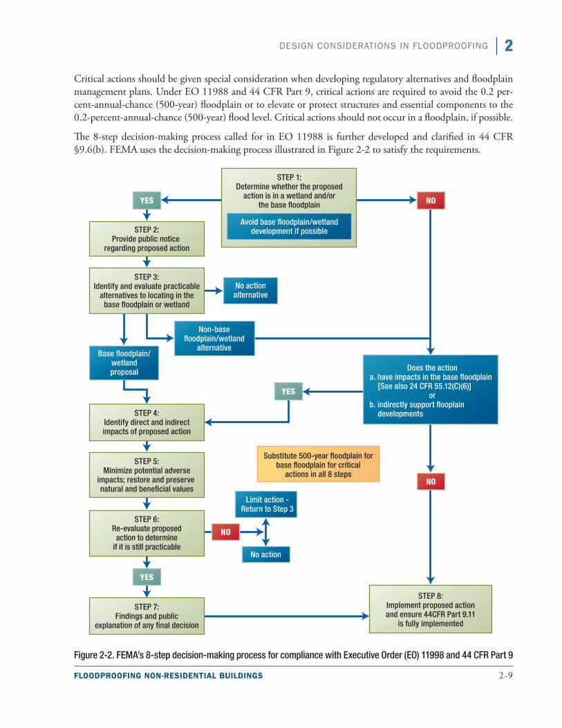
FLOODPROOFING NON-RESIDENTIAL BUILDINGS 2-9
2DESIGN CONSIDERATIONS IN FLOODPROOFING
Critical actions should be given special consideration when developing regulatory alternatives and floodplain management plans. Under EO 11988 and 44 CFR Part 9, critical actions are required to avoid the 0.2 per-cent-annual-chance (500-year) floodplain or to elevate or protect structures and essential components to the 0.2-percent-annual-chance (500-year) flood level. Critical actions should not occur in a floodplain, if possible.
The 8-step decision-making process called for in EO 11988 is further developed and clarified in 44 CFR §9.6(b). FEMA uses the decision-making process illustrated in Figure 2-2 to satisfy the requirements.
Figure 2-2. FEMA’s 8-step decision-making process for compliance with Executive Order (EO) 11998 and 44 CFR Part 9
2-10 FLOODPROOFING NON-RESIDENTIAL BUILDINGS
2 DESIGN CONSIDERATIONS IN FLOODPROOFING
2.1.5 Local Floodplain Management Regulations
To participate in the NFIP, communities are required to adopt and enforce local floodplain management regulations that meet or exceed the minimum requirements established in 44 CFR Parts 59 and 60. Until the advent of model building codes that included flood provisions deemed consistent with NFIP requirements for buildings (see Section 2.1.1), communities adopted stand-alone floodplain management regulations or ordinances that included administrative, land use, and building requirements.
Some States have requirements that exceed the minimum NFIP requirements, and many communities adopt higher standards to achieve a greater level of protection and public safety. The most common higher standards are:
■■ Requirement to protect to a higher elevation than the minimum requirement (freeboard)
■■ A cumulative Substantial Improvement in which the improvements and repairs are tallied over a certain period of time (e.g., 5 or 10 years). The effect of a cumulative improvement provision is that more existing buildings are required to be brought into compliance with the requirements for new construction
■■ Prohibition of new construction in the floodway, SFHA, or conservation zones
■■ Prohibition of the use of building materials and practices that have proven to be ineffective in flooding
■■ Restrictions on the use and type of construction fill material
2.1.6 Model Building Codes
Many States and communities regulate the construction of buildings by adopting and enforcing building codes based on model building codes. Building codes have minimum requirements on issues such as structural design, materials, fire safety, number and location of exits, natural hazard mitigation, sanitary facilities, light and ventilation, environmental control, fire protection, and energy conservation. Building codes apply to the construction of new buildings and structures and to existing buildings and structures, including alteration, relocation, enlargement, replacement, repair, and change of occupancy.
The I-Codes and the National Fire Protection Association (NFPA) Building Construction and Safety Code (NFPA 5000 [2012]) were the first model codes to include comprehensive provisions for flood hazards. The flood provisions were incorporated into building codes in the early 2000s. Both codes are consistent with the minimum provisions of the NFIP that pertain to the design and construction of buildings and other structures.
The IBC and International Existing Building Code (IEBC [2012]) are pertinent to this manual because they address the primary requirements for design and construction of non-residential buildings and because of their widespread use in the United States. The IBC contains flood provisions, and the IEBC references the flood provisions of the IBC for all repairs, additions, and alterations to existing buildings in flood hazard areas that are proposed to be Substantially Improved or that have sustained Substantial Damage.
Warning
For any building that is proposed for dry floodproofing, always determine whether the community where the building is locat-ed has adopted higher standards.
FLOODPROOFING NON-RESIDENTIAL BUILDINGS 2-11
2DESIGN CONSIDERATIONS IN FLOODPROOFING
The IBC incorporates by reference a number of standards developed through a formal or accredited consensus process. The standards that are related to flood-resis-tant design are ASCE 7, Minimum Design Loads for Buildings and Other Structures, and ASCE 24, Flood Resistant Design and Construction. The IBC addresses flood loads and flood-resistant construction primarily in Section 1612. FEMA has determined that the flood provisions of the I-Codes are consistent with NFIP requirements for buildings and structures. The family of I-Codes addresses all of the key building requirements of the NFIP. Communities that enforce building codes based on the I-Codes should coordinate their floodplain management ordinances with the codes to minimize duplication and conflicts and to ensure that all requirements are addressed, including requirements for devel-opment other than buildings and structures.
Some key code requirements from the 2012 IBC are described in Table 2-3 (previous editions of the IBC have the same or similar requirements).
A dry floodproofing retrofit project may trigger several sections of a community’s building code that must be considered during the design. The designer or engineer should be cognizant of codes that may be triggered when considering flood mitigation projects (see code trigger example on page 2-13).
Cross Reference
The International Code Council’s family of building codes can be purchased at http://www.iccsafe.org/. The I-Codes are NOT available for free (although some States have made them available through sepa-rate copyright agreements). Excerpts of the flood provisions of the I-Codes are posted on the FEMA Building Science Web site: http://www.fema.gov/building-science.
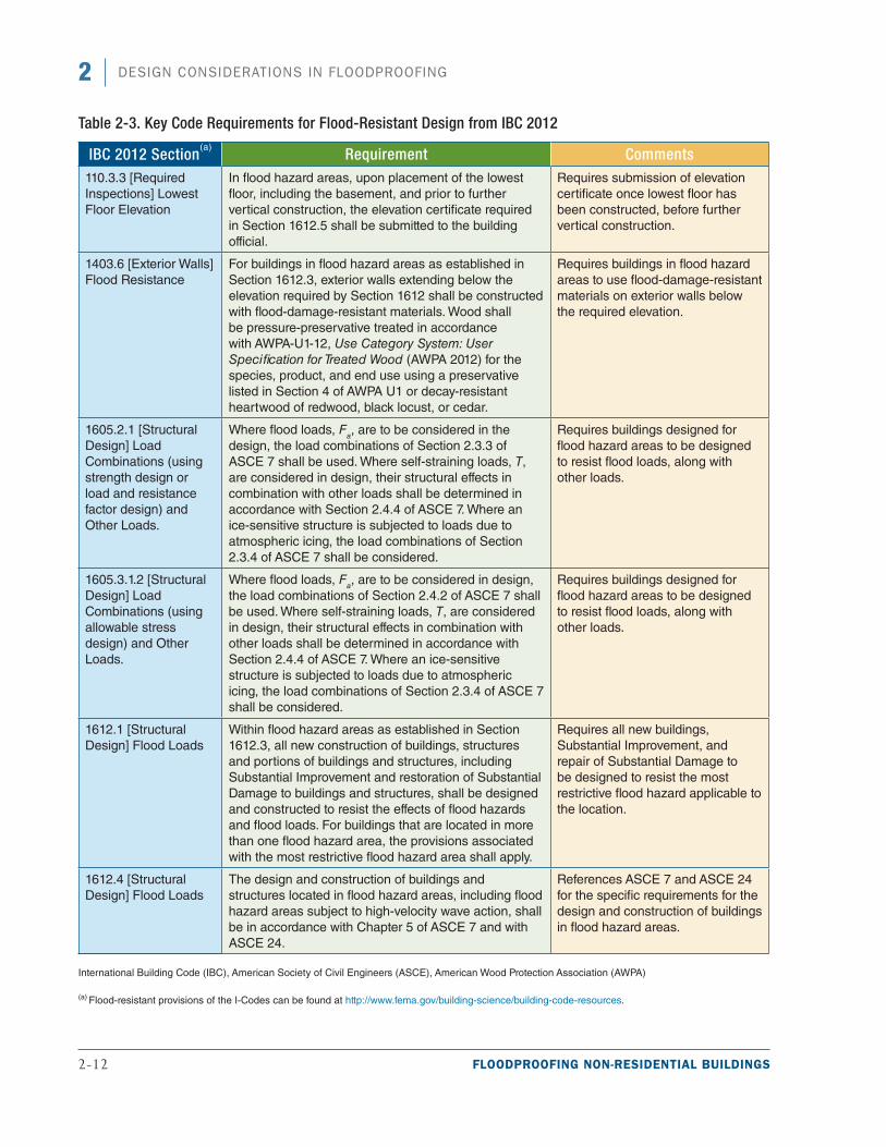
2-12 FLOODPROOFING NON-RESIDENTIAL BUILDINGS
2 DESIGN CONSIDERATIONS IN FLOODPROOFING
Table 2-3. Key Code Requirements for Flood-Resistant Design from IBC 2012
IBC 2012 Section(a)
Requirement Comments110.3.3 [Required Inspections] Lowest Floor Elevation
In flood hazard areas, upon placement of the lowest floor, including the basement, and prior to further vertical construction, the elevation certificate required in Section 1612.5 shall be submitted to the building official.
Requires submission of elevation certificate once lowest floor has been constructed, before further vertical construction.
1403.6 [Exterior Walls] Flood Resistance
For buildings in flood hazard areas as established in Section 1612.3, exterior walls extending below the elevation required by Section 1612 shall be constructed with flood-damage-resistant materials. Wood shall be pressure-preservative treated in accordance with AWPA-U1-12, Use Category System: User Specification for Treated Wood (AWPA 2012) for the species, product, and end use using a preservative listed in Section 4 of AWPA U1 or decay-resistant heartwood of redwood, black locust, or cedar.
Requires buildings in flood hazard areas to use flood-damage-resistant materials on exterior walls below the required elevation.
1605.2.1 [Structural Design] Load Combinations (using strength design or load and resistance factor design) and Other Loads.
Where flood loads, Fa, are to be considered in the
design, the load combinations of Section 2.3.3 of ASCE 7 shall be used. Where self-straining loads, T, are considered in design, their structural effects in combination with other loads shall be determined in accordance with Section 2.4.4 of ASCE 7. Where an ice-sensitive structure is subjected to loads due to atmospheric icing, the load combinations of Section 2.3.4 of ASCE 7 shall be considered.
Requires buildings designed for flood hazard areas to be designed to resist flood loads, along with other loads.
1605.3.1.2 [Structural Design] Load Combinations (using allowable stress design) and Other Loads.
Where flood loads, Fa, are to be considered in design, the load combinations of Section 2.4.2 of ASCE 7 shall be used. Where self-straining loads, T, are considered in design, their structural effects in combination with other loads shall be determined in accordance with Section 2.4.4 of ASCE 7. Where an ice-sensitive structure is subjected to loads due to atmospheric icing, the load combinations of Section 2.3.4 of ASCE 7 shall be considered.
Requires buildings designed for flood hazard areas to be designed to resist flood loads, along with other loads.
1612.1 [Structural Design] Flood Loads
Within flood hazard areas as established in Section 1612.3, all new construction of buildings, structures and portions of buildings and structures, including Substantial Improvement and restoration of Substantial Damage to buildings and structures, shall be designed and constructed to resist the effects of flood hazards and flood loads. For buildings that are located in more than one flood hazard area, the provisions associated with the most restrictive flood hazard area shall apply.
Requires all new buildings, Substantial Improvement, and repair of Substantial Damage to be designed to resist the most restrictive flood hazard applicable to the location.
1612.4 [Structural Design] Flood Loads
The design and construction of buildings and structures located in flood hazard areas, including flood hazard areas subject to high-velocity wave action, shall be in accordance with Chapter 5 of ASCE 7 and with ASCE 24.
References ASCE 7 and ASCE 24 for the specific requirements for the design and construction of buildings in flood hazard areas.
International Building Code (IBC), American Society of Civil Engineers (ASCE), American Wood Protection Association (AWPA)
(a) Flood-resistant provisions of the I-Codes can be found at http://www.fema.gov/building-science/building-code-resources.
FLOODPROOFING NON-RESIDENTIAL BUILDINGS 2-13
2DESIGN CONSIDERATIONS IN FLOODPROOFING
2.1.7 Consensus Standards
The consensus standards relevant to flood-resistant design are ASCE 7 and ASCE 24. The requirements in these standards are consistent with the minimum NFIP requirements.
ASCE 7 outlines methods to determine design loads and load combinations in flood hazard areas, includ-ing hydrostatic loads, hydrodynamic loads, wave loads, and debris impact loads. To compute the loads and load combinations, the designer must identify site-spe-cific characteristics, including flood depths, velocities, waves, and the likelihood that debris impacts need to be considered.
ASCE 24 addresses design and construction require-ments for buildings in flood hazard areas, including floodways, coastal high hazard areas, and other high-risk flood hazard areas such as alluvial fans, flash flood areas, mudslide areas, erosion-prone areas, and high-velocity areas. ASCE 24 sets forth requirements for elevation, foundation designs, enclosures below elevated buildings, materials, dry and wet floodproofing, utility
Code Trigger Example
An example of a requirement that could be triggered by a floodproofing retrofit project is means of egress. The IEBC has criteria on means of egress that may be relevant depending on the level of altera-tion. Level 2 alterations “include the reconfiguration of space, the addition or elimination of any door or window, the reconfiguration or extension of any system, or the installation of any additional equipment.” Under the IEBC, in a Level 2 alteration, the requirements for both Level 1 and Level 2 alterations need to be followed. The requirements may involve finish, structural, accessibility/egress, fire-resistance, and other requirements. For example, a Level 2 alteration may trigger means of egress requirements that include:
■ Minimum number of exits in the work area, as required by the IBC (some buildings are required to have only one exit if certain criteria are met
■ Fire escapes requirements such as unobstructed access
■ New fire escape requirements
■ Mezzanine egress requirements
■ Requirements for openings in corridor walls
■ Means of egress lighting, exit signs, handrails, and guard
Warning
ASCE 24 addresses design and con-struction requirements for buildings in coastal high-hazard areas (Zone V), Coastal A Zones, and high-flood-veloci-ty areas but limits the applications of dry floodproofing in these areas because of increased hydrodynamic and wave loads.
Cross Reference
ASCE standards are available for purchase at: http://www.asce.org/codes-standards/. Highlights of ASCE 24 are posted on the FEMA Building Science Web page: http://www.fema.gov/building-science.
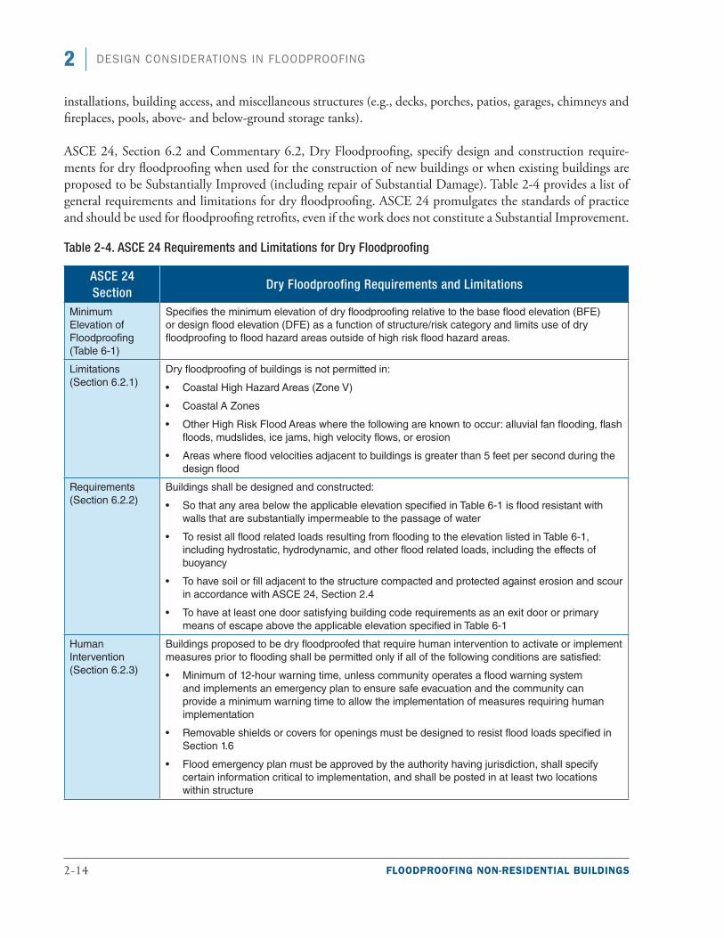
2-14 FLOODPROOFING NON-RESIDENTIAL BUILDINGS
2 DESIGN CONSIDERATIONS IN FLOODPROOFING
installations, building access, and miscellaneous structures (e.g., decks, porches, patios, garages, chimneys and fireplaces, pools, above- and below-ground storage tanks).
ASCE 24, Section 6.2 and Commentary 6.2, Dry Floodproofing, specify design and construction require-ments for dry floodproofing when used for the construction of new buildings or when existing buildings are proposed to be Substantially Improved (including repair of Substantial Damage). Table 2-4 provides a list of general requirements and limitations for dry floodproofing. ASCE 24 promulgates the standards of practice and should be used for floodproofing retrofits, even if the work does not constitute a Substantial Improvement.
Table 2-4. ASCE 24 Requirements and Limitations for Dry Floodproofing
ASCE 24 Section
Dry Floodproofing Requirements and Limitations
Minimum Elevation of Floodproofing (Table 6-1)
Specifies the minimum elevation of dry floodproofing relative to the base flood elevation (BFE) or design flood elevation (DFE) as a function of structure/risk category and limits use of dry floodproofing to flood hazard areas outside of high risk flood hazard areas.
Limitations (Section 6.2.1)
Dry floodproofing of buildings is not permitted in:
■• Coastal High Hazard Areas (Zone V)
■• Coastal A Zones
■• Other High Risk Flood Areas where the following are known to occur: alluvial fan flooding, flash floods, mudslides, ice jams, high velocity flows, or erosion
■• Areas where flood velocities adjacent to buildings is greater than 5 feet per second during the design flood
Requirements (Section 6.2.2)
Buildings shall be designed and constructed:
■• So that any area below the applicable elevation specified in Table 6-1 is flood resistant with walls that are substantially impermeable to the passage of water
■• To resist all flood related loads resulting from flooding to the elevation listed in Table 6-1, including hydrostatic, hydrodynamic, and other flood related loads, including the effects of buoyancy
■• To have soil or fill adjacent to the structure compacted and protected against erosion and scour in accordance with ASCE 24, Section 2.4
■• To have at least one door satisfying building code requirements as an exit door or primary means of escape above the applicable elevation specified in Table 6-1
Human Intervention (Section 6.2.3)
Buildings proposed to be dry floodproofed that require human intervention to activate or implement measures prior to flooding shall be permitted only if all of the following conditions are satisfied:
■• Minimum of 12-hour warning time, unless community operates a flood warning system and implements an emergency plan to ensure safe evacuation and the community can provide a minimum warning time to allow the implementation of measures requiring human implementation
■• Removable shields or covers for openings must be designed to resist flood loads specified in Section 1.6
■• Flood emergency plan must be approved by the authority having jurisdiction, shall specify certain information critical to implementation, and shall be posted in at least two locations within structure
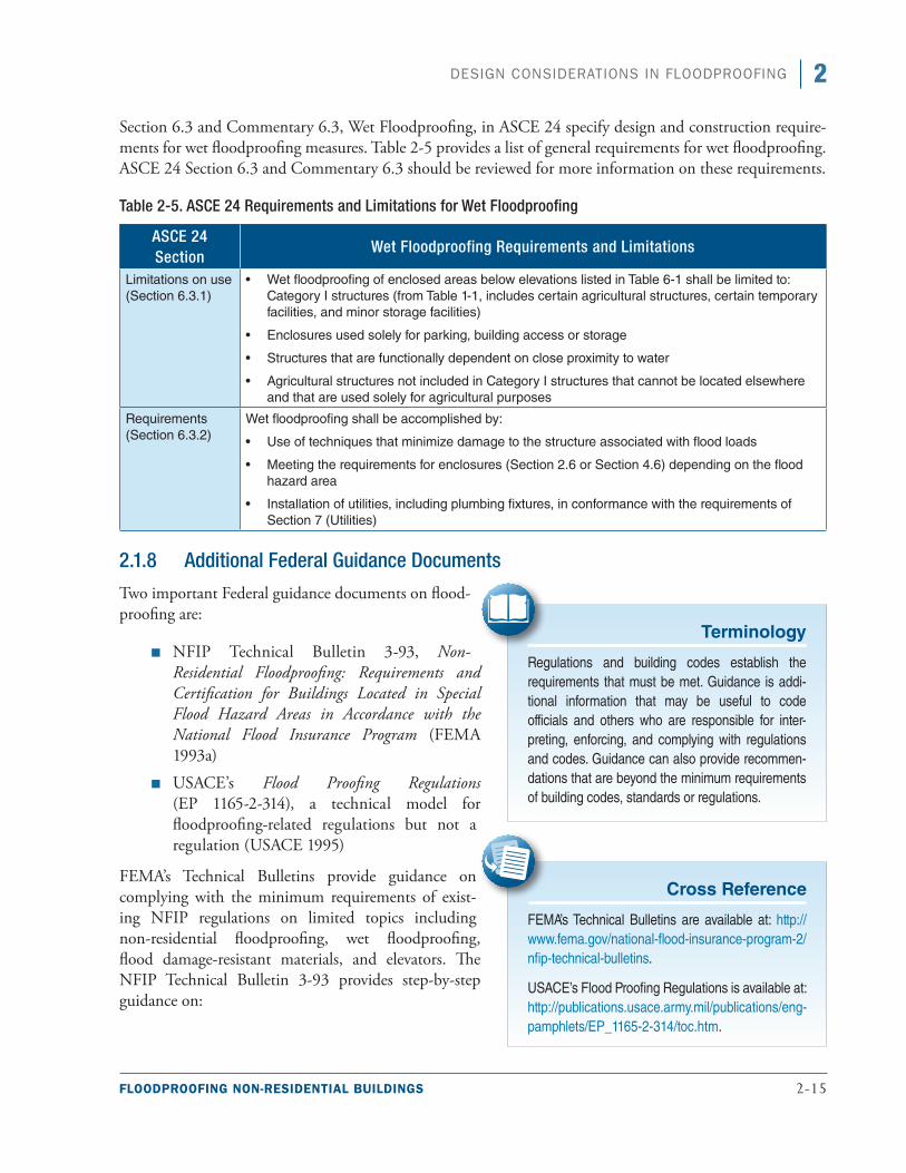
FLOODPROOFING NON-RESIDENTIAL BUILDINGS 2-15
2DESIGN CONSIDERATIONS IN FLOODPROOFING
Section 6.3 and Commentary 6.3, Wet Floodproofing, in ASCE 24 specify design and construction require-ments for wet floodproofing measures. Table 2-5 provides a list of general requirements for wet floodproofing. ASCE 24 Section 6.3 and Commentary 6.3 should be reviewed for more information on these requirements.
Table 2-5. ASCE 24 Requirements and Limitations for Wet Floodproofing
ASCE 24 Section
Wet Floodproofing Requirements and Limitations
Limitations on use (Section 6.3.1)
■• Wet floodproofing of enclosed areas below elevations listed in Table 6-1 shall be limited to: Category I structures (from Table 1-1, includes certain agricultural structures, certain temporary facilities, and minor storage facilities)
■• Enclosures used solely for parking, building access or storage
■• Structures that are functionally dependent on close proximity to water
■• Agricultural structures not included in Category I structures that cannot be located elsewhere and that are used solely for agricultural purposes
Requirements (Section 6.3.2)
Wet floodproofing shall be accomplished by:
■• Use of techniques that minimize damage to the structure associated with flood loads
■• Meeting the requirements for enclosures (Section 2.6 or Section 4.6) depending on the flood hazard area
■• Installation of utilities, including plumbing fixtures, in conformance with the requirements of Section 7 (Utilities)
2.1.8 Additional Federal Guidance Documents
Two important Federal guidance documents on flood-proofing are:
■■ NFIP Technical Bulletin 3-93, Non-Residential Floodproofing: Requirements and Certification for Buildings Located in Special Flood Hazard Areas in Accordance with the National Flood Insurance Program (FEMA 1993a)
■■ USACE’s Flood Proofing Regulations (EP 1165-2-314), a technical model for floodproofing-related regulations but not a regulation (USACE 1995)
FEMA’s Technical Bulletins provide guidance on complying with the minimum requirements of exist-ing NFIP regulations on limited topics including non-residential floodproofing, wet floodproofing, flood damage-resistant materials, and elevators. The NFIP Technical Bulletin 3-93 provides step-by-step guidance on:
Terminology
Regulations and building codes establish the requirements that must be met. Guidance is addi-tional information that may be useful to code officials and others who are responsible for inter-preting, enforcing, and complying with regulations and codes. Guidance can also provide recommen-dations that are beyond the minimum requirements of building codes, standards or regulations.
Cross Reference
FEMA’s Technical Bulletins are available at: http://www.fema.gov/national-flood-insurance-program-2/nfip-technical-bulletins.
USACE’s Flood Proofing Regulations is available at: http://publications.usace.army.mil/publications/eng-pamphlets/EP_1165-2-314/toc.htm.
2-16 FLOODPROOFING NON-RESIDENTIAL BUILDINGS
2 DESIGN CONSIDERATIONS IN FLOODPROOFING
■■ NFIP regulations that apply to the design of floodproofing for non-residential buildings
■■ Planning considerations (e.g., warning time, flood characteristics)
■■ Minimum engineering considerations and equations for calculating flood forces
■■ Preparing the Floodproofing Certificate for Non-Residential Structures (see Section 2.1.2)
USACE’s Flood Proofing Regulations was among the earliest documents to provide an administrative and technical model for code design and enforcement and to present detailed information on implementing flood-proofing techniques. It has served as the framework for the preparation of numerous other floodproofing publications. Flood Proofing Regulations pertains to riverine flooding and does not address wave action, cor-rosion, or erosion associated with coastal flooding, debris impact, mudslides, or high-density fluid problems.
2.2 Design Loads and Site Characteristics Floodproofing measures must ensure that buildings will be designed and constructed to resist flotation, col-lapse, and lateral movement associated with flooding. The loads and conditions discussed in this section include but are not limited to:
■■ Flood-related hazards such as hydrostatic and hydrodynamic loads, flood-borne debris impact loads, and internal and site drainage considerations
■■ Site-specific soil and geotechnical considerations such as soil pressure, bearing capacity, land subsidence, erosion, scour, and shrink-swell potential
This section provides an overview of how these forces can act on a building. See FEMA P-259, Engineering Principles and Practices for Retrofitting Flood-Prone Residential Structures (FEMA 2012a) for more informa-tion on flood-related loads and conditions.
2.2.1 Identifying the Base Flood Elevation
Determining the expected BFE is critical to understanding the site-specific flood risk. The flood zone and esti-mated BFE of a project area are identified using a FIRM panel. Flood hazard area boundaries on many FIRMs are delineated for the 1- and 0.2-percent-annual-chance (100-year and 500-year) flood.
Figure 2-3 shows the location of a subject building on a FIRM. The area with blue dots is the 1-percent-annual-chance (100-year) flood hazard area. The area with black dots is the 0.2-percent-annual-chance (500-year) flood hazard area. After the building is located on the FIRM, the flood profiles in the relevant Flood Insurance Study (FIS) should be used to verify the BFE and to determine the flood elevations for other modeled flood recurrence intervals.
Cross Reference
For areas in which BFEs have not been established, designers can refer to FEMA 265 Zone A Manual: Managing Floodplain Development in Approximate Zone A Areas (FEMA 1995) (http://www.fema.gov/media-library/assets/documents/7273). This guide provides information on obtaining and devel-oping BFEs.
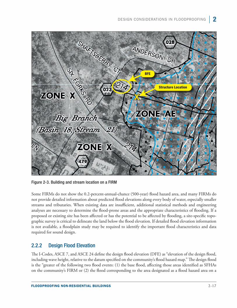
FLOODPROOFING NON-RESIDENTIAL BUILDINGS 2-17
2DESIGN CONSIDERATIONS IN FLOODPROOFING
Figure 2-3. Building and stream location on a FIRM
Some FIRMs do not show the 0.2-percent-annual-chance (500-year) flood hazard area, and many FIRMs do not provide detailed information about predicted flood elevations along every body of water, especially smaller streams and tributaries. When existing data are insufficient, additional statistical methods and engineering analyses are necessary to determine the flood-prone areas and the appropriate characteristics of flooding. If a proposed or existing site has been affected or has the potential to be affected by flooding, a site-specific topo-graphic survey is critical to delineate the land below the flood elevation. If detailed flood elevation information is not available, a floodplain study may be required to identify the important flood characteristics and data required for sound design.
2.2.2 Design Flood Elevation
The I-Codes, ASCE 7, and ASCE 24 define the design flood elevation (DFE) as “elevation of the design flood, including wave height, relative to the datum specified on the community’s flood hazard map.” The design flood is the “greater of the following two flood events: (1) the base flood, affecting those areas identified as SFHAs on the community’s FIRM or (2) the flood corresponding to the area designated as a flood hazard area on a
2-18 FLOODPROOFING NON-RESIDENTIAL BUILDINGS
2 DESIGN CONSIDERATIONS IN FLOODPROOFING
community’s flood hazard map or otherwise legally designated.” Some communities use the DFE to refer to the BFE plus locally required additional height (usually referred to as “freeboard”).
The I-Codes and ASCE 24 specify the elevation of buildings or the elevation of floodproofing measures based on the Occupancy/Risk Category of the building. All buildings are required to be assigned a category, which is then used in ASCE 24 to determine the level of protection. The more important the building, as indicated by the assigned category, the higher the level of protection.
2.2.3 Determining the Flood Depth
The first step in determining the flood depth for a site is to identify the DFE that is specified by the build-ing code or the floodplain management regulations that are enforced by the governing authority. The most common flood elevation used for design is the BFE. ASCE 24 requires some height of freeboard above the BFE, the amount of which is determined by the build-ing occupancy. Local regulations and requirements should be compared to ASCE 24, and the most restric-tive condition should be followed.
Terminology
Base flood elevation (BFE) – The elevation of the base flood relative to the datum specified on a community’s FIRM. The base flood has a 1-percent chance of being equaled or exceeded in any given year (commonly called the 100-year flood). BFEs are shown on FIRMs for many SFHAs. The BFE is the NFIP’s minimum elevation to which the lowest floor of a building must be elevated or floodproofed (Zone A). In Zone V, the bottom of the lowest horizontal structural member must be elevated to or above the BFE; floodproofing is not permitted in Zone V. Many SFHAs are shown on FIRMs without BFEs; in these areas, community officials and permit applicants are required to obtain and use information from other sources, or must estimate or develop BFEs at specific locations.
Freeboard – An added margin of safety, expressed in feet above a specific flood elevation, usually the BFE. In States and communities that require freeboard, buildings are required to be elevated or flood-proofed to the higher elevation. For example, if a community adopts a 2-foot freeboard, non-residential buildings are required to be elevated or floodproofed to 2 feet above the BFE.
Design flood elevation (DFE) – The elevation of the design flood relative to the datum specified on the community’s FIRM. The design flood is associated with the greater of the area subject to the base flood or the area designated as a flood hazard area on a community flood map or otherwise designated. The I-Codes, ASCE 7, and ASCE 24 use the term DFE. In most communities, the DFE is identical to the BFE. Communities may designate a design flood (or DFE) in order to regulate based on a flood of record, to account for future increases in flood levels based on upland development, or to incorporate freeboard.
Cross Reference
The FEMA publication, Managing Floodplain Development through the NFIP, IS-9 (FEMA 2007a), provides guidance on determining flood elevations through flood profiles in the FIS. The document can be downloaded here: http://www.fema.gov/media-library/assets/documents/6029.
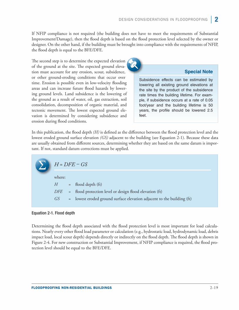
FLOODPROOFING NON-RESIDENTIAL BUILDINGS 2-19
2DESIGN CONSIDERATIONS IN FLOODPROOFING
If NFIP compliance is not required (the building does not have to meet the requirements of Substantial Improvement/Damage), then the flood depth is based on the flood protection level selected by the owner or designer. On the other hand, if the building must be brought into compliance with the requirements of NFIP, the flood depth is equal to the BFE/DFE.
The second step is to determine the expected elevation of the ground at the site. The expected ground eleva-tion must account for any erosion, scour, subsidence, or other ground-eroding conditions that occur over time. Erosion is possible even in low-velocity flooding areas and can increase future flood hazards by lower-ing ground levels. Land subsidence is the lowering of the ground as a result of water, oil, gas extraction, soil consolidation, decomposition of organic material, and tectonic movement. The lowest expected ground ele-vation is determined by considering subsidence and erosion during flood conditions.
In this publication, the flood depth (H) is defined as the difference between the flood protection level and the lowest eroded ground surface elevation (GS) adjacent to the building (see Equation 2-1). Because these data are usually obtained from different sources, determining whether they are based on the same datum is impor-tant. If not, standard datum corrections must be applied.
H = DFE – GS
where:
H = flood depth (ft)
DFE = flood protection level or design flood elevation (ft)
GS = lowest eroded ground surface elevation adjacent to the building (ft)
Equation 2-1. Flood depth
Determining the flood depth associated with the flood protection level is most important for load calcula-tions. Nearly every other flood load parameter or calculation (e.g., hydrostatic load, hydrodynamic load, debris impact load, local scour depth) depends directly or indirectly on the flood depth. The flood depth is shown in Figure 2-4. For new construction or Substantial Improvement, if NFIP compliance is required, the flood pro-tection level should be equal to the BFE/DFE.
Special Note
Subsidence effects can be estimated by lowering all existing ground elevations at the site by the product of the subsidence rate times the building lifetime. For exam-ple, if subsidence occurs at a rate of 0.05 foot/year and the building lifetime is 50 years, the profile should be lowered 2.5 feet.
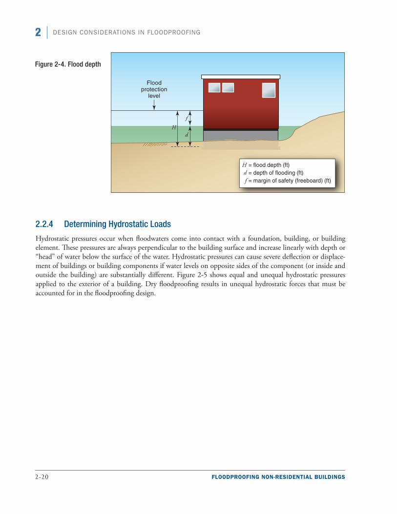
2-20 FLOODPROOFING NON-RESIDENTIAL BUILDINGS
2 DESIGN CONSIDERATIONS IN FLOODPROOFING
2.2.4 Determining Hydrostatic Loads
Hydrostatic pressures occur when floodwaters come into contact with a foundation, building, or building element. These pressures are always perpendicular to the building surface and increase linearly with depth or “head” of water below the surface of the water. Hydrostatic pressures can cause severe deflection or displace-ment of buildings or building components if water levels on opposite sides of the component (or inside and outside the building) are substantially different. Figure 2-5 shows equal and unequal hydrostatic pressures applied to the exterior of a building. Dry floodproofing results in unequal hydrostatic forces that must be accounted for in the floodproofing design.
Figure 2-4. Flood depth
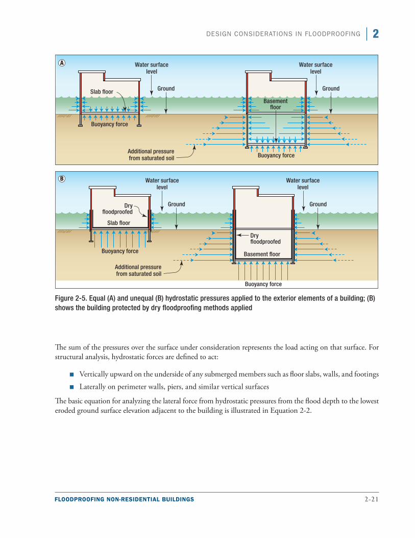
FLOODPROOFING NON-RESIDENTIAL BUILDINGS 2-21
2DESIGN CONSIDERATIONS IN FLOODPROOFING
Figure 2-5. Equal (A) and unequal (B) hydrostatic pressures applied to the exterior elements of a building; (B) shows the building protected by dry floodproofing methods applied
The sum of the pressures over the surface under consideration represents the load acting on that surface. For structural analysis, hydrostatic forces are defined to act:
■■ Vertically upward on the underside of any submerged members such as floor slabs, walls, and footings
■■ Laterally on perimeter walls, piers, and similar vertical surfaces
The basic equation for analyzing the lateral force from hydrostatic pressures from the flood depth to the lowest eroded ground surface elevation adjacent to the building is illustrated in Equation 2-2.
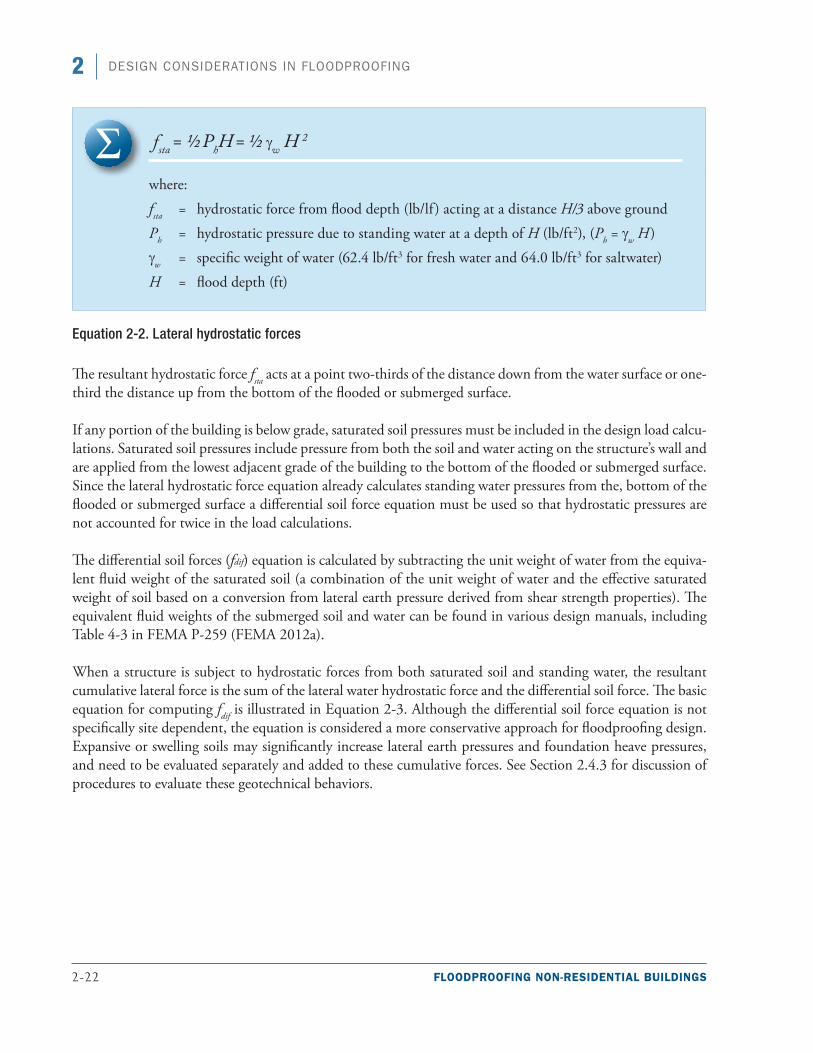
2-22 FLOODPROOFING NON-RESIDENTIAL BUILDINGS
2 DESIGN CONSIDERATIONS IN FLOODPROOFING
fsta = ½ PhH = ½ γw H 2
where:
fsta = hydrostatic force from flood depth (lb/lf) acting at a distance H/3 above ground
Ph = hydrostatic pressure due to standing water at a depth of H (lb/ft2), (Ph = γw H)
γw = specific weight of water (62.4 lb/ft3 for fresh water and 64.0 lb/ft3 for saltwater)
H = flood depth (ft)
Equation 2-2. Lateral hydrostatic forces
The resultant hydrostatic force fsta acts at a point two-thirds of the distance down from the water surface or one-third the distance up from the bottom of the flooded or submerged surface.
If any portion of the building is below grade, saturated soil pressures must be included in the design load calcu-lations. Saturated soil pressures include pressure from both the soil and water acting on the structure’s wall and are applied from the lowest adjacent grade of the building to the bottom of the flooded or submerged surface. Since the lateral hydrostatic force equation already calculates standing water pressures from the, bottom of the flooded or submerged surface a differential soil force equation must be used so that hydrostatic pressures are not accounted for twice in the load calculations.
The differential soil forces (fdif) equation is calculated by subtracting the unit weight of water from the equiva-lent fluid weight of the saturated soil (a combination of the unit weight of water and the effective saturated weight of soil based on a conversion from lateral earth pressure derived from shear strength properties). The equivalent fluid weights of the submerged soil and water can be found in various design manuals, including Table 4-3 in FEMA P-259 (FEMA 2012a).
When a structure is subject to hydrostatic forces from both saturated soil and standing water, the resultant cumulative lateral force is the sum of the lateral water hydrostatic force and the differential soil force. The basic equation for computing fdif is illustrated in Equation 2-3. Although the differential soil force equation is not specifically site dependent, the equation is considered a more conservative approach for floodproofing design. Expansive or swelling soils may significantly increase lateral earth pressures and foundation heave pressures, and need to be evaluated separately and added to these cumulative forces. See Section 2.4.3 for discussion of procedures to evaluate these geotechnical behaviors.
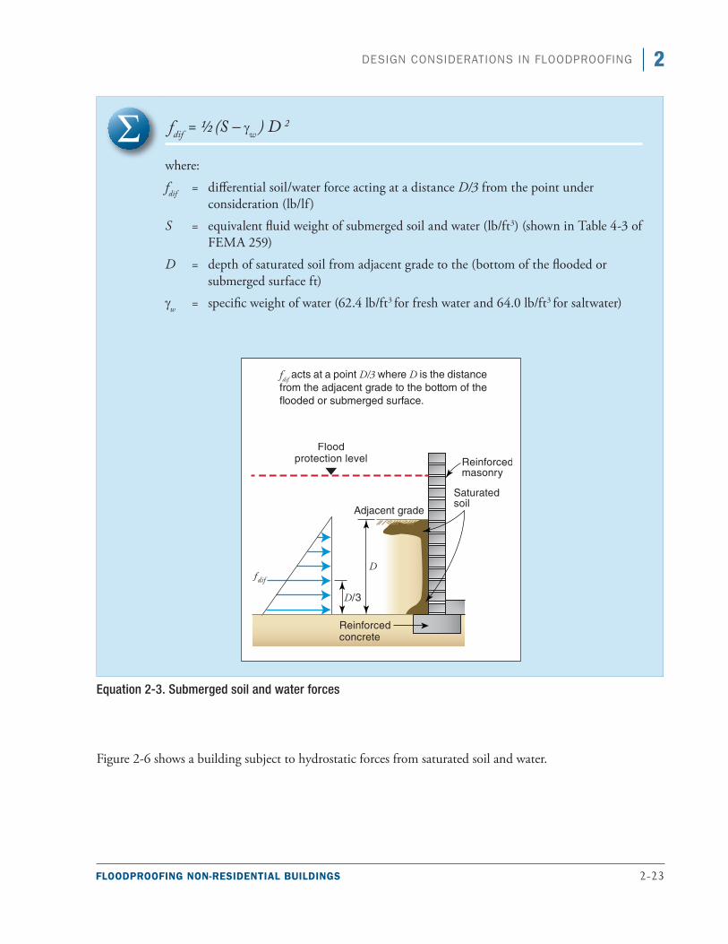
FLOODPROOFING NON-RESIDENTIAL BUILDINGS 2-23
2DESIGN CONSIDERATIONS IN FLOODPROOFING
fdif = ½ (S – γw ) D 2
where:
fdif = differential soil/water force acting at a distance D/3 from the point under consideration (lb/lf)
S = equivalent fluid weight of submerged soil and water (lb/ft3) (shown in Table 4-3 of FEMA 259)
D = depth of saturated soil from adjacent grade to the (bottom of the flooded or submerged surface ft)
γw = specific weight of water (62.4 lb/ft3 for fresh water and 64.0 lb/ft3 for saltwater)
Equation 2-3. Submerged soil and water forces
Figure 2-6 shows a building subject to hydrostatic forces from saturated soil and water.
fdif acts at a point D/3 where D is the distance from the adjacent grade to the bottom of the flooded or submerged surface.
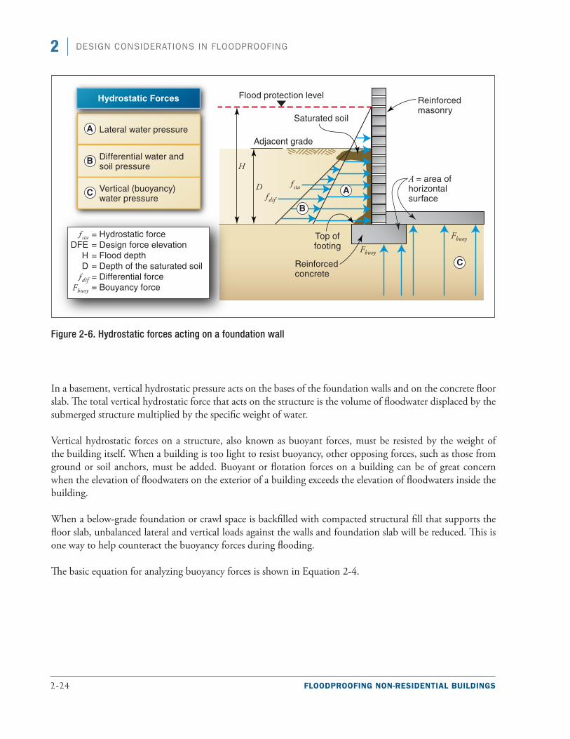
2-24 FLOODPROOFING NON-RESIDENTIAL BUILDINGS
2 DESIGN CONSIDERATIONS IN FLOODPROOFING
Figure 2-6. Hydrostatic forces acting on a foundation wall
In a basement, vertical hydrostatic pressure acts on the bases of the foundation walls and on the concrete floor slab. The total vertical hydrostatic force that acts on the structure is the volume of floodwater displaced by the submerged structure multiplied by the specific weight of water.
Vertical hydrostatic forces on a structure, also known as buoyant forces, must be resisted by the weight of the building itself. When a building is too light to resist buoyancy, other opposing forces, such as those from ground or soil anchors, must be added. Buoyant or flotation forces on a building can be of great concern when the elevation of floodwaters on the exterior of a building exceeds the elevation of floodwaters inside the building.
When a below-grade foundation or crawl space is backfilled with compacted structural fill that supports the floor slab, unbalanced lateral and vertical loads against the walls and foundation slab will be reduced. This is one way to help counteract the buoyancy forces during flooding.
The basic equation for analyzing buoyancy forces is shown in Equation 2-4.
FLOODPROOFING NON-RESIDENTIAL BUILDINGS 2-25
2DESIGN CONSIDERATIONS IN FLOODPROOFING
Fbuoy = γw (Vol)
where:
Fbuoy = vertical hydrostatic force resulting from the displacement of a given volume of floodwater (lb)
γw = specific weight of water (62.4 lb/ft3 for fresh water and 64.0 lb/ft3 for saltwater)
Vol = volume of floodwater displaced by a submerged object (ft3)
Equation 2-4. Buoyancy forces
As noted in Equation 2-4, the specific weight of freshwater is 62.4 pounds per cubic foot (lb/ft3), while the spe-cific weight of saltwater is slightly higher at 64 lb/ft3. Both fresh and saltwater are relatively dense, so buoyant forces can be extreme. For example, the buoyant forces on a 24-by-36-foot foundation with 4 feet of freshwater flooding can be as high as 214,272 pounds (24 ft x 36 ft x 4 ft x 62 lb/ft3). Approximately 250,000 pounds of buoyant force will exceed the weight of all but the heaviest structures. It is assumed that the foundation walls and slab are substantially impermeable to the passage of water. Buildings with substantially impermeable base-ment walls and floor that have sump pumps to remove water that enters the basement can experience increased buoyant forces. When substantially impermeable buildings with below-grade areas are exposed to flooding, they can actually float on the floodwaters they displace.
The computation of hydrostatic forces is vital to the successful design of floodwalls, sealants, closures, shields, foundation walls, slabs, and a variety of other dry floodproofing measures. Computation of these forces is illus-trated in Sections 4.1.2.2 through 4.1.2.6 of FEMA P-259.
2.2.5 Determining Hydrodynamic Forces
Water flowing around a building, structural elements, and other submerged objects imposes loads on sub-merged building elements. These loads are known as hydrodynamic loads (see Figure 2-7). Hydrodynamic loads are a function of flow velocity and structural geometry and include frontal impact on the upstream face, drag along the sides, and suction on the down-stream side. One of the most difficult steps in quantifying loads imposed by moving water is deter-mining the expected floodwater velocity.
Special Note
Sources of data for determining expected flood velocity include hydraulic calculations, historical measurements, Risk Mapping, Assessment, and Planning (Risk MAP) velocity data grids, and rules of thumb. If no data exist for flood flow velocity for a site, contact an experienced hydrologist or hydraulic engineer for estimates.
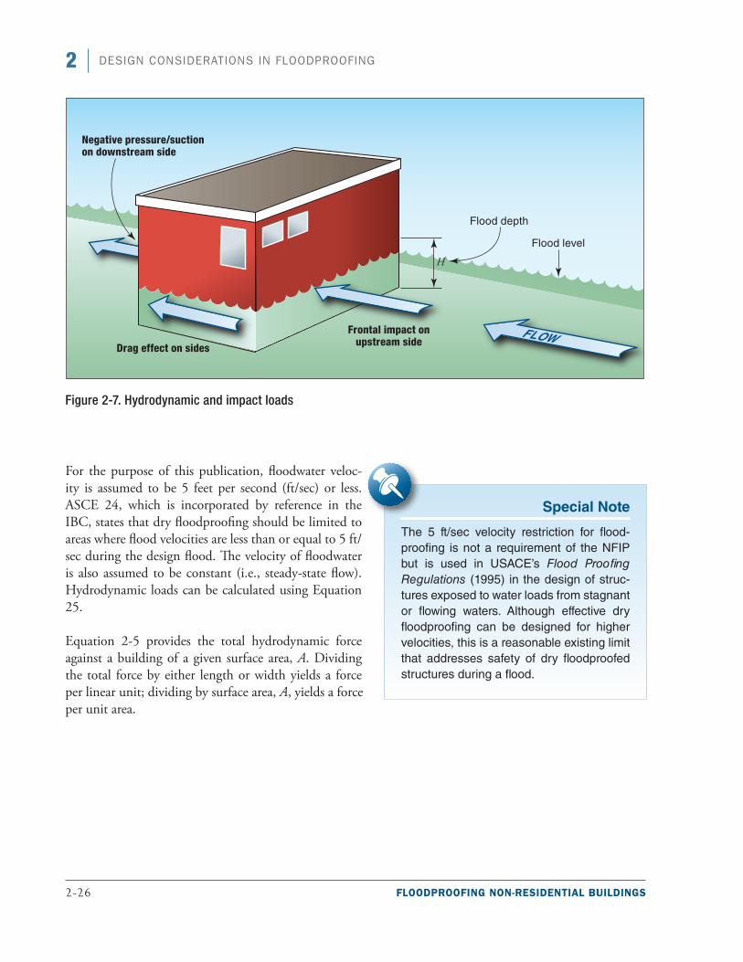
2-26 FLOODPROOFING NON-RESIDENTIAL BUILDINGS
2 DESIGN CONSIDERATIONS IN FLOODPROOFING
Figure 2-7. Hydrodynamic and impact loads
For the purpose of this publication, floodwater veloc-ity is assumed to be 5 feet per second (ft/sec) or less. ASCE 24, which is incorporated by reference in the IBC, states that dry floodproofing should be limited to areas where flood velocities are less than or equal to 5 ft/sec during the design flood. The velocity of floodwater is also assumed to be constant (i.e., steady-state flow). Hydrodynamic loads can be calculated using Equation 25.
Equation 2-5 provides the total hydrodynamic force against a building of a given surface area, A. Dividing the total force by either length or width yields a force per linear unit; dividing by surface area, A, yields a force per unit area.
Special Note
The 5 ft/sec velocity restriction for flood-proofing is not a requirement of the NFIP but is used in USACE’s Flood Proofing Regulations (1995) in the design of struc-tures exposed to water loads from stagnant or flowing waters. Although effective dry floodproofing can be designed for higher velocities, this is a reasonable existing limit that addresses safety of dry floodproofed structures during a flood.
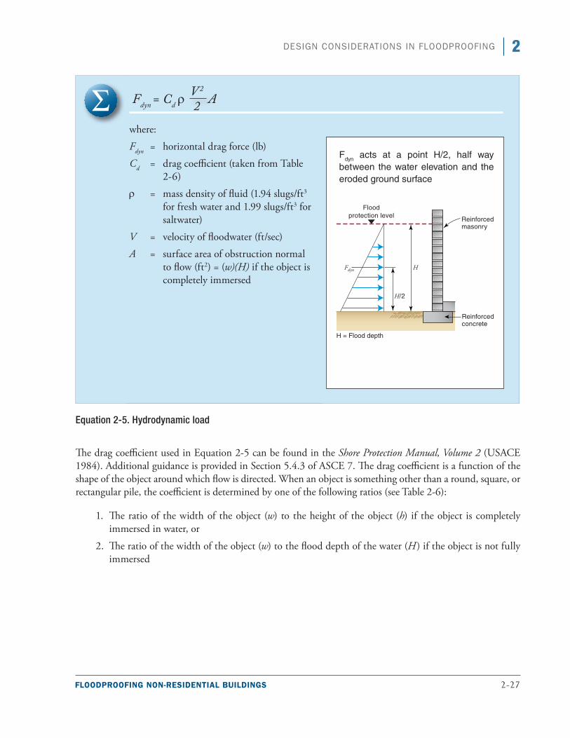
FLOODPROOFING NON-RESIDENTIAL BUILDINGS 2-27
2DESIGN CONSIDERATIONS IN FLOODPROOFING
Fdyn = Cd r A
where:
Fdyn = horizontal drag force (lb)
Cd = drag coefficient (taken from Table 2-6)
r = mass density of fluid (1.94 slugs/ft3
for fresh water and 1.99 slugs/ft3 for saltwater)
V = velocity of floodwater (ft/sec)
A = surface area of obstruction normal to flow (ft2) = (w)(H) if the object is completely immersed
Equation 2-5. Hydrodynamic load
The drag coefficient used in Equation 2-5 can be found in the Shore Protection Manual, Volume 2 (USACE 1984). Additional guidance is provided in Section 5.4.3 of ASCE 7. The drag coefficient is a function of the shape of the object around which flow is directed. When an object is something other than a round, square, or rectangular pile, the coefficient is determined by one of the following ratios (see Table 2-6):
1. The ratio of the width of the object (w) to the height of the object (h) if the object is completely immersed in water, or
2. The ratio of the width of the object (w) to the flood depth of the water (H) if the object is not fully immersed
V 2
2
Fdyn acts at a point H/2, half way between the water elevation and the eroded ground surface
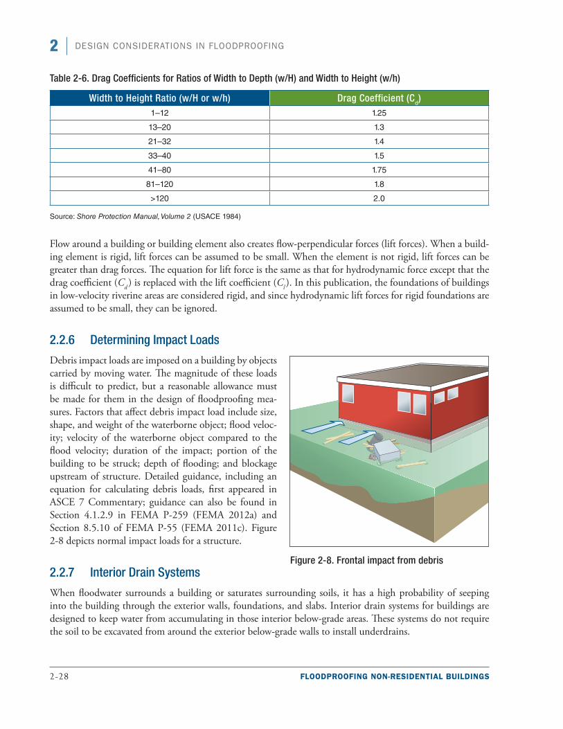
2-28 FLOODPROOFING NON-RESIDENTIAL BUILDINGS
2 DESIGN CONSIDERATIONS IN FLOODPROOFING
Table 2-6. Drag Coefficients for Ratios of Width to Depth (w/H) and Width to Height (w/h)
Width to Height Ratio (w/H or w/h) Drag Coefficient (Cd)1–12 1.25
13–20 1.3
21–32 1.4
33–40 1.5
41–80 1.75
81–120 1.8
>120 2.0
Source: Shore Protection Manual, Volume 2 (USACE 1984)
Flow around a building or building element also creates flow-perpendicular forces (lift forces). When a build-ing element is rigid, lift forces can be assumed to be small. When the element is not rigid, lift forces can be greater than drag forces. The equation for lift force is the same as that for hydrodynamic force except that the drag coefficient (Cd ) is replaced with the lift coefficient (Cl ). In this publication, the foundations of buildings in low-velocity riverine areas are considered rigid, and since hydrodynamic lift forces for rigid foundations are assumed to be small, they can be ignored.
2.2.6 Determining Impact Loads
Debris impact loads are imposed on a building by objects carried by moving water. The magnitude of these loads is difficult to predict, but a reasonable allowance must be made for them in the design of floodproofing mea-sures. Factors that affect debris impact load include size, shape, and weight of the waterborne object; flood veloc-ity; velocity of the waterborne object compared to the flood velocity; duration of the impact; portion of the building to be struck; depth of flooding; and blockage upstream of structure. Detailed guidance, including an equation for calculating debris loads, first appeared in ASCE 7 Commentary; guidance can also be found in Section 4.1.2.9 in FEMA P-259 (FEMA 2012a) and Section 8.5.10 of FEMA P-55 (FEMA 2011c). Figure 2-8 depicts normal impact loads for a structure.
2.2.7 Interior Drain Systems
When floodwater surrounds a building or saturates surrounding soils, it has a high probability of seeping into the building through the exterior walls, foundations, and slabs. Interior drain systems for buildings are designed to keep water from accumulating in those interior below-grade areas. These systems do not require the soil to be excavated from around the exterior below-grade walls to install underdrains.
Figure 2-8. Frontal impact from debris
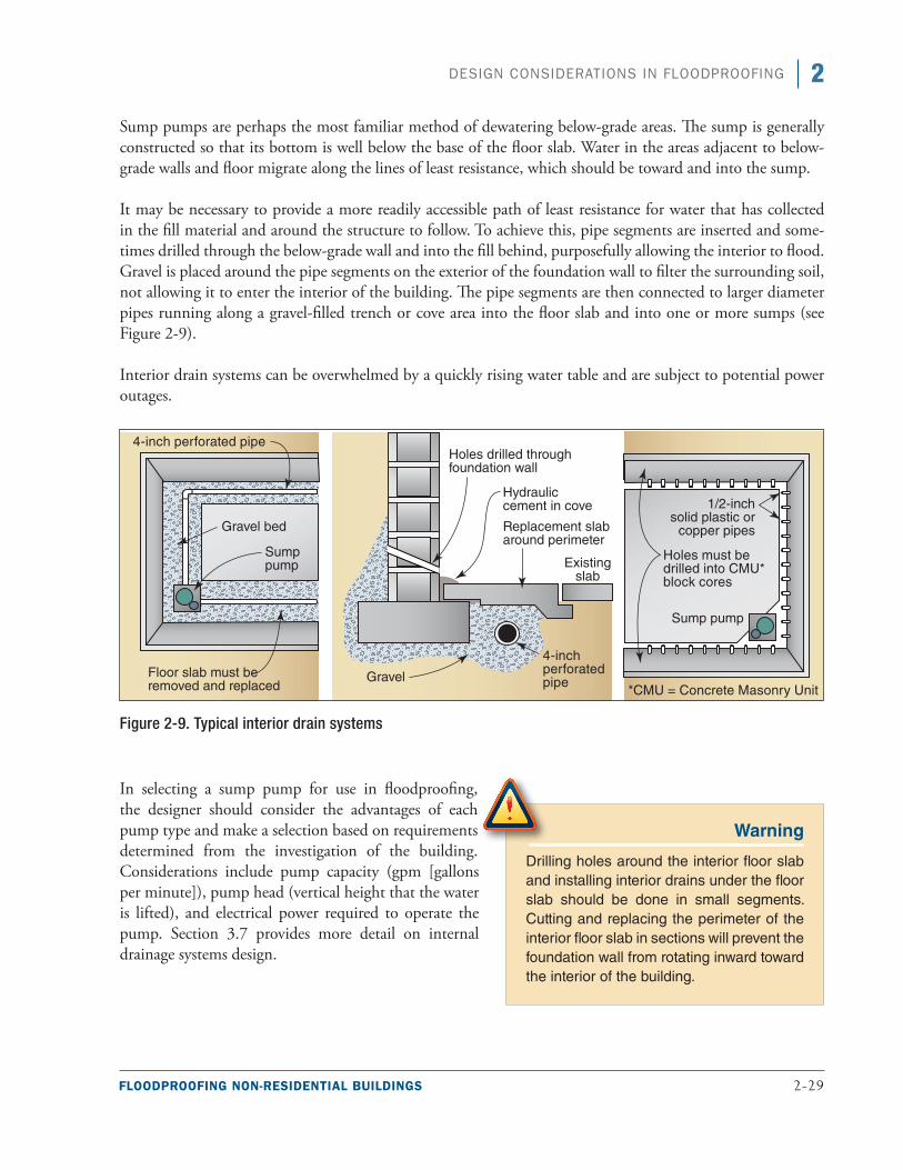
FLOODPROOFING NON-RESIDENTIAL BUILDINGS 2-29
2DESIGN CONSIDERATIONS IN FLOODPROOFING
Sump pumps are perhaps the most familiar method of dewatering below-grade areas. The sump is generally constructed so that its bottom is well below the base of the floor slab. Water in the areas adjacent to below-grade walls and floor migrate along the lines of least resistance, which should be toward and into the sump.
It may be necessary to provide a more readily accessible path of least resistance for water that has collected in the fill material and around the structure to follow. To achieve this, pipe segments are inserted and some-times drilled through the below-grade wall and into the fill behind, purposefully allowing the interior to flood. Gravel is placed around the pipe segments on the exterior of the foundation wall to filter the surrounding soil, not allowing it to enter the interior of the building. The pipe segments are then connected to larger diameter pipes running along a gravel-filled trench or cove area into the floor slab and into one or more sumps (see Figure 2-9).
Interior drain systems can be overwhelmed by a quickly rising water table and are subject to potential power outages.
Figure 2-9. Typical interior drain systems
In selecting a sump pump for use in floodproofing, the designer should consider the advantages of each pump type and make a selection based on requirements determined from the investigation of the building. Considerations include pump capacity (gpm [gallons per minute]), pump head (vertical height that the water is lifted), and electrical power required to operate the pump. Section 3.7 provides more detail on internal drainage systems design.
Warning
Drilling holes around the interior floor slab and installing interior drains under the floor slab should be done in small segments. Cutting and replacing the perimeter of the interior floor slab in sections will prevent the foundation wall from rotating inward toward the interior of the building.
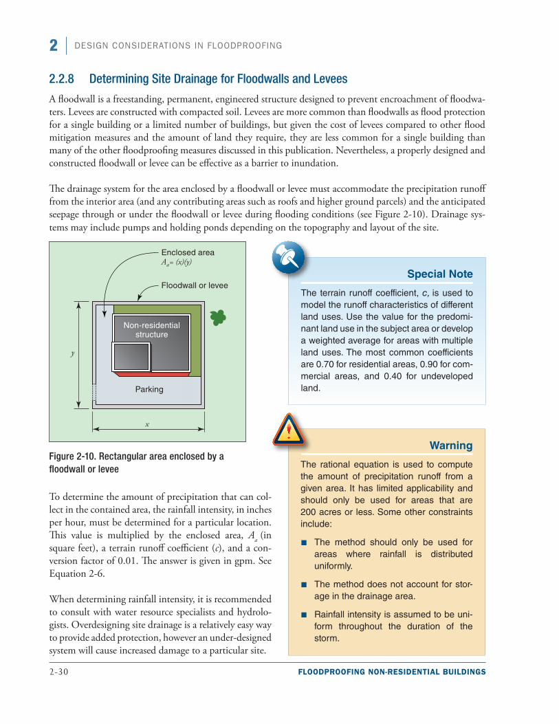
2-30 FLOODPROOFING NON-RESIDENTIAL BUILDINGS
2 DESIGN CONSIDERATIONS IN FLOODPROOFING
2.2.8 Determining Site Drainage for Floodwalls and Levees
A floodwall is a freestanding, permanent, engineered structure designed to prevent encroachment of floodwa-ters. Levees are constructed with compacted soil. Levees are more common than floodwalls as flood protection for a single building or a limited number of buildings, but given the cost of levees compared to other flood mitigation measures and the amount of land they require, they are less common for a single building than many of the other floodproofing measures discussed in this publication. Nevertheless, a properly designed and constructed floodwall or levee can be effective as a barrier to inundation.
The drainage system for the area enclosed by a floodwall or levee must accommodate the precipitation runoff from the interior area (and any contributing areas such as roofs and higher ground parcels) and the anticipated seepage through or under the floodwall or levee during flooding conditions (see Figure 2-10). Drainage sys-tems may include pumps and holding ponds depending on the topography and layout of the site.
Figure 2-10. Rectangular area enclosed by a floodwall or levee
To determine the amount of precipitation that can col-lect in the contained area, the rainfall intensity, in inches per hour, must be determined for a particular location. This value is multiplied by the enclosed area, Aa (in square feet), a terrain runoff coefficient (c), and a con-version factor of 0.01. The answer is given in gpm. See Equation 2-6.
When determining rainfall intensity, it is recommended to consult with water resource specialists and hydrolo-gists. Overdesigning site drainage is a relatively easy way to provide added protection, however an under-designed system will cause increased damage to a particular site.
Warning
The rational equation is used to compute the amount of precipitation runoff from a given area. It has limited applicability and should only be used for areas that are 200 acres or less. Some other constraints include:
■ The method should only be used for areas where rainfall is distributed uniformly.
■ The method does not account for stor-age in the drainage area.
■ Rainfall intensity is assumed to be uni-form throughout the duration of the storm.
Special Note
The terrain runoff coefficient, c, is used to model the runoff characteristics of different land uses. Use the value for the predomi-nant land use in the subject area or develop a weighted average for areas with multiple land uses. The most common coefficients are 0.70 for residential areas, 0.90 for com-mercial areas, and 0.40 for undeveloped land.
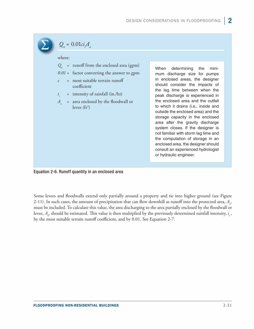
FLOODPROOFING NON-RESIDENTIAL BUILDINGS 2-31
2DESIGN CONSIDERATIONS IN FLOODPROOFING
Qa = 0.01cirAa
where:
Qa = runoff from the enclosed area (gpm)
0.01 = factor converting the answer to gpm
c = most suitable terrain runoff coefficient
ir = intensity of rainfall (in./hr)
Aa = area enclosed by the floodwall or levee (ft2)
Equation 2-6. Runoff quantity in an enclosed area
Some levees and floodwalls extend only partially around a property and tie into higher ground (see Figure 2-11). In such cases, the amount of precipitation that can flow downhill as runoff into the protected area, Aa, must be included. To calculate this value, the area discharging to the area partially enclosed by the floodwall or levee, Ab, should be estimated. This value is then multiplied by the previously determined rainfall intensity, ir , by the most suitable terrain runoff coefficient, and by 0.01. See Equation 2-7.
When determining the mini-mum discharge size for pumps in enclosed areas, the designer should consider the impacts of the lag time between when the peak discharge is experienced in the enclosed area and the outfall to which it drains (i.e., inside and outside the enclosed area) and the storage capacity in the enclosed area after the gravity discharge system closes. If the designer is not familiar with storm lag time and the computation of storage in an enclosed area, the designer should consult an experienced hydrologist or hydraulic engineer.
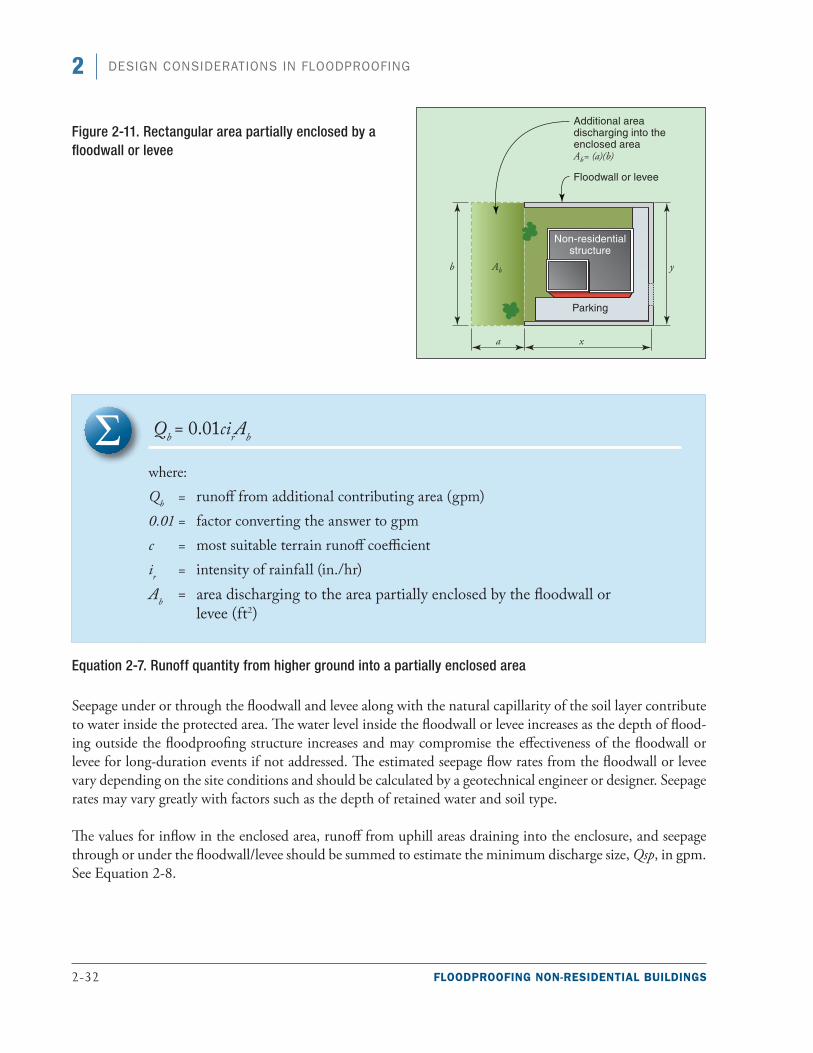
2-32 FLOODPROOFING NON-RESIDENTIAL BUILDINGS
2 DESIGN CONSIDERATIONS IN FLOODPROOFING
Qb = 0.01cirAb
where:
Qb = runoff from additional contributing area (gpm) 0.01 = factor converting the answer to gpmc = most suitable terrain runoff coefficient ir = intensity of rainfall (in./hr) Ab = area discharging to the area partially enclosed by the floodwall or
levee (ft2)
Equation 2-7. Runoff quantity from higher ground into a partially enclosed area
Seepage under or through the floodwall and levee along with the natural capillarity of the soil layer contribute to water inside the protected area. The water level inside the floodwall or levee increases as the depth of flood-ing outside the floodproofing structure increases and may compromise the effectiveness of the floodwall or levee for long-duration events if not addressed. The estimated seepage flow rates from the floodwall or levee vary depending on the site conditions and should be calculated by a geotechnical engineer or designer. Seepage rates may vary greatly with factors such as the depth of retained water and soil type.
The values for inflow in the enclosed area, runoff from uphill areas draining into the enclosure, and seepage through or under the floodwall/levee should be summed to estimate the minimum discharge size, Qsp, in gpm. See Equation 2-8.
Figure 2-11. Rectangular area partially enclosed by a floodwall or levee
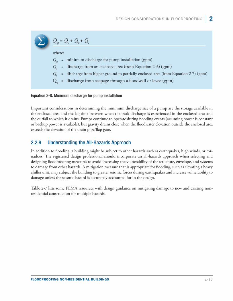
FLOODPROOFING NON-RESIDENTIAL BUILDINGS 2-33
2DESIGN CONSIDERATIONS IN FLOODPROOFING
Qsp = Qa + Qb + Qc
where:
Qsp = minimum discharge for pump installation (gpm)Qa = discharge from an enclosed area (from Equation 2-6) (gpm)Qb = discharge from higher ground to partially enclosed area (from Equation 2-7) (gpm)
Qc = discharge from seepage through a floodwall or levee (gpm)
Equation 2-8. Minimum discharge for pump installation
Important considerations in determining the minimum discharge size of a pump are the storage available in the enclosed area and the lag time between when the peak discharge is experienced in the enclosed area and the outfall to which it drains. Pumps continue to operate during flooding events (assuming power is constant or backup power is available), but gravity drains close when the floodwater elevation outside the enclosed area exceeds the elevation of the drain pipe/flap gate.
2.2.9 Understanding the All-Hazards Approach
In addition to flooding, a building might be subject to other hazards such as earthquakes, high winds, or tor-nadoes. The registered design professional should incorporate an all-hazards approach when selecting and designing floodproofing measures to avoid increasing the vulnerability of the structure, envelope, and systems to damage from other hazards. A mitigation measure that is appropriate for flooding, such as elevating a heavy chiller unit, may subject the building to greater seismic forces during earthquakes and increase vulnerability to damage unless the seismic hazard is accurately accounted for in the design.
Table 2-7 lists some FEMA resources with design guidance on mitigating damage to new and existing non-residential construction for multiple hazards.
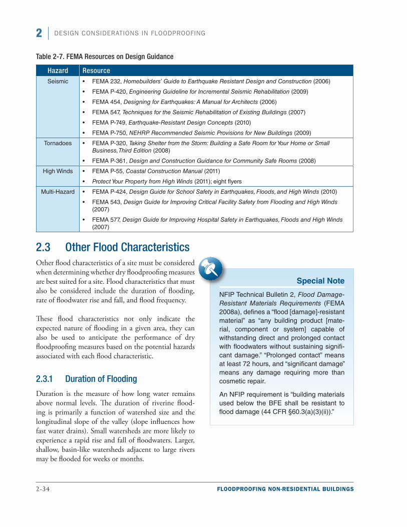
2-34 FLOODPROOFING NON-RESIDENTIAL BUILDINGS
2 DESIGN CONSIDERATIONS IN FLOODPROOFING
Table 2-7. FEMA Resources on Design Guidance
Hazard ResourceSeismic ■• FEMA 232, Homebuilders’ Guide to Earthquake Resistant Design and Construction (2006)
■• FEMA P-420, Engineering Guideline for Incremental Seismic Rehabilitation (2009)
■• FEMA 454, Designing for Earthquakes: A Manual for Architects (2006)
■• FEMA 547, Techniques for the Seismic Rehabilitation of Existing Buildings (2007)
■• FEMA P-749, Earthquake-Resistant Design Concepts (2010)
■• FEMA P-750, NEHRP Recommended Seismic Provisions for New Buildings (2009)
Tornadoes ■• FEMA P-320, Taking Shelter from the Storm: Building a Safe Room for Your Home or Small Business, Third Edition (2008)
■• FEMA P-361, Design and Construction Guidance for Community Safe Rooms (2008)
High Winds ■• FEMA P-55, Coastal Construction Manual (2011)
■• Protect Your Property from High Winds (2011); eight flyers
Multi-Hazard ■• FEMA P-424, Design Guide for School Safety in Earthquakes, Floods, and High Winds (2010)
■• FEMA 543, Design Guide for Improving Critical Facility Safety from Flooding and High Winds (2007)
■• FEMA 577, Design Guide for Improving Hospital Safety in Earthquakes, Floods and High Winds (2007)
2.3 Other Flood CharacteristicsOther flood characteristics of a site must be considered when determining whether dry floodproofing measures are best suited for a site. Flood characteristics that must also be considered include the duration of flooding, rate of floodwater rise and fall, and flood frequency.
These flood characteristics not only indicate the expected nature of flooding in a given area, they can also be used to anticipate the performance of dry floodproofing measures based on the potential hazards associated with each flood characteristic.
2.3.1 Duration of Flooding
Duration is the measure of how long water remains above normal levels. The duration of riverine flood-ing is primarily a function of watershed size and the longitudinal slope of the valley (slope influences how fast water drains). Small watersheds are more likely to experience a rapid rise and fall of floodwaters. Larger, shallow, basin-like watersheds adjacent to large rivers may be flooded for weeks or months.
Special Note
NFIP Technical Bulletin 2, Flood Damage-Resistant Materials Requirements (FEMA 2008a), defines a “flood [damage]-resistant material” as “any building product [mate-rial, component or system] capable of withstanding direct and prolonged contact with floodwaters without sustaining signifi-cant damage.” “Prolonged contact” means at least 72 hours, and “significant damage” means any damage requiring more than cosmetic repair.
An NFIP requirement is “building materials used below the BFE shall be resistant to flood damage (44 CFR §60.3(a)(3)(ii)).”
FLOODPROOFING NON-RESIDENTIAL BUILDINGS 2-35
2DESIGN CONSIDERATIONS IN FLOODPROOFING
Prolonged contact with floodwaters may make some mitigation measures, including dry floodproofing, inappropriate because of the increased chance of seepage and potential structural failure. Long periods of inundation are more likely to cause greater damage to structural members and finishes than short periods of flooding. Increased durations also result in a higher probability of floodwater accumulation and ultimately affects pump design for interior drainage. Designers should consider the duration of flooding when determin-ing the applicability of selected building materials, pump design, and flood mitigation measures.
2.3.2 Rate of Floodwater Rise and Fall
Steep topography and locations with small drain-age areas may experience flash flooding, an event in which floodwater can rise very quickly with little or no warning. High-velocity water flows usually accom-pany flash floods and preclude certain types of flood mitigation measures, especially those requiring human intervention.
If a building is susceptible to flash floods, insufficient warning time may make the timely installation of shields on windows, doors, and floodwalls and the acti-vation of pump systems and backup energy sources impossible. Temporarily relocating movable contents to a higher level may also be impractical. Floodproofing is not appropriate for sites in flash flood areas because of the potentially short warning time. Active floodproofing measures (those requiring human intervention) may be effective if a building is not subject to flash flooding and the area has adequate flood warning systems.
Rapid rates of the rise and fall of floodwater can also lead to unequal hydrostatic pressures on a building. The probability of unequal hydrostatic pressures increases when building exteriors are designed to be watertight.
2.3.3 Flood Frequency
Flood frequency analyses define the probability that a flood of a specific size will be equaled or exceeded in any given year. A flood elevation with a 1-percent-annual-chance flood of being equaled or exceeded in a given year is referred to as the “base flood,” com-monly called the 100-year flood. Figure 2-12 illustrates the relationship between flood recurrence intervals and the probability of the event occurring within a given period. The probability that a base flood will be equaled or exceeded is 26 percent during a 30-year period. During a 70-year period (the potential useful life of many buildings), the probability increases to 50 percent. Although the base flood serves as the basis for NFIP insurance rates and regulatory floodplain man-agement requirements, the relative frequency of any
Special Note
Although buildings are required to be protected only to the BFE for floodplain management purposes (to meet the NFIP regulations), protection to a higher level is necessary for the floodproofing measures to be considered for flood insurance rating purposes. It is possible to protect buildings from lesser flood events using dry flood-proofing measures, but doing so will not bring buildings into compliance with the NFIP.
Warning
ASCE 24 does not permit the use of dry floodproofing for buildings in high-risk flood hazard areas. These include alluvial fan, flash flood, mudslide, erosion-prone, high-velocity, wave action, and ice jam and debris-prone areas.
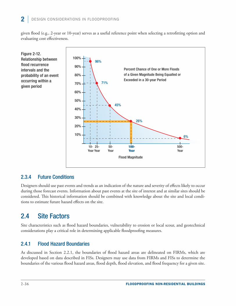
2-36 FLOODPROOFING NON-RESIDENTIAL BUILDINGS
2 DESIGN CONSIDERATIONS IN FLOODPROOFING
given flood (e.g., 2-year or 10-year) serves as a useful reference point when selecting a retrofitting option and evaluating cost effectiveness.
2.3.4 Future Conditions
Designers should use past events and trends as an indication of the nature and severity of effects likely to occur during those forecast events. Information about past events at the site of interest and at similar sites should be considered. This historical information should be combined with knowledge about the site and local condi-tions to estimate future hazard effects on the site.
2.4 Site FactorsSite characteristics such as flood hazard boundaries, vulnerability to erosion or local scour, and geotechnical considerations play a critical role in determining applicable floodproofing measures.
2.4.1 Flood Hazard Boundaries
As discussed in Section 2.2.1, the boundaries of flood hazard areas are delineated on FIRMs, which are developed based on data described in FISs. Designers may use data from FIRMs and FISs to determine the boundaries of the various flood hazard areas, flood depth, flood elevation, and flood frequency for a given site.
Figure 2-12. Relationship between flood recurrence intervals and the probability of an event occurring within a given period
FLOODPROOFING NON-RESIDENTIAL BUILDINGS 2-37
2DESIGN CONSIDERATIONS IN FLOODPROOFING
In addition to the aforementioned flood characteristics that can affect buildings, site location in relation to the floodplain is also an important factor when considering dry floodproofing. Designers should note whether buildings are in or near the floodway, on the floodway fringe, near road crossings or other obstructions because these may divert floodwaters toward the site.
2.4.2 Erosion
Erosion refers to the wearing or washing away of land and can occur in riverine as well as in coastal environ-ments. Erosion is difficult to predict and is capable of threatening existing structures by lowering ground elevations, causing instability and failure in embankments, and transporting sediments landward or down-stream. Erosion may also increase flood forces by increasing water depths. Erosion may be caused by natural actions such as flood-inducing storms and may be exacerbated by human actions such as constructing flood diversion or flood protection structures, dredging channels, damming rivers, and altering surface vegetation.
Riverine erosion affects the stability of stream banks and adjacent structures through the interaction of mul-tiple geophysical and geotechnical factors. Variables that affect the stability (or erodibility) of stream banks include:
■■ Slope
■■ Critical height
■■ Inclination
■■ Cohesive strength of the soil in the slope
■■ Level and variation of groundwater in the slope
■■ Degree of stabilization of the surface of the slope
■■ Level and variation in level of water on the toe of the slope
■■ Distance of the structure in question from the shoulder of the stream bank
■■ Shear strength of the soil
■■ Frequency of rise and fall of the surface of the stream
Consideration of siting and the erodibility of land is critical when planning floodproofing projects because moving floodwater can undermine foundations and cause building, floodwall, and levee failure. Shallow foundation systems generally do not provide sufficient protection against soil erosion without some type of additional protection or armoring measure of below-grade elements. The local office of the Natural Resources Conservation Service has information concerning the erodibility of the soils native to a specific site, and com-munity officials may have knowledge of local soil types and know whether erosion has occurred during past floods.
The analysis of erosion impacts to stream banks and nearby structures is a detailed effort that is usually accom-panied by detailed geotechnical investigations.
2-38 FLOODPROOFING NON-RESIDENTIAL BUILDINGS
2 DESIGN CONSIDERATIONS IN FLOODPROOFING
2.4.3 Geotechnical Considerations
Site-specific soil properties are important factors in the design of any surface intended to resist flood loads. The properties include:
■■ Saturated soil forces
■■ Allowable bearing capacity
■■ Potential for scour
■■ Land subsidence
■■ Frost zone location
■■ Permeability
■■ Shrink-swell potential
The computation of lateral soil forces and determination of soil-bearing capacity are critical in the design of dry floodproofed foundations and walls. These forces and related geotechnical behaviors include a consider-ation of the frost depth, potential expansive or collapsible soils, or potential scour and erosion, and play an important role in selecting an acceptable foundation. Likewise, the permeability and compaction behavior of soils are key factors in selecting borrow materials for backfill, levee, or floodwall construction. For more infor-mation on these geotechnical issues, see Chapter 4 of FEMA P259 (2012a).
Site investigations for soils include surface and subsurface investigations. Surface investigations can identify the potential for landslides and evidence of areas affected by erosion or scour, determine accessibility for equipment needed for subsurface testing and construction, and help identify the suitability of a particular foundation type based on the performance of existing structures. Subsurface exploration provides invaluable data on soils below grade. The data are both qualitative (e.g., soil classification) and quantitative (e.g., bear-ing capacity). Subsurface exploration is complex and site-dependent. For example, testing for expansive soil requires assessing samples at various depths for plasticity, expansion index, and swell pressure to determine resulting swell forces under saturation conditions. Consultation with a geotechnical engineer familiar with the site is strongly recommended.
2.5 Functional, Operational, and Economic Factors The functional, operational, and economic factors that should be considered when determining the appropri-ate floodproofing method for a building are:
■■ Functional use requirements of the building (how the flood-prone portions of the building are used)
■■ Occupant safety
■■ Flood warning time
■■ Flood emergency operations plan
■■ Inspection and maintenance plan
■■ Economic factors
FLOODPROOFING NON-RESIDENTIAL BUILDINGS 2-39
2DESIGN CONSIDERATIONS IN FLOODPROOFING
2.5.1 Functional Use Requirements of the Building
The functions of non-residential buildings and whether active floodproofing measures (those requiring human intervention) can be used affect the types of floodproofing measures that are appropriate. For example, if a doorway that may be vulnerable to flooding is used by personnel and for freight delivery, permanently filling in the doorway is not feasible. Likewise, if extended interruption of function would be detrimental, floodproof-ing is not feasible because personnel should not occupy a building that is affected by floodwaters. Relocation may be a better option in this situation.
The current and future use of buildings must be evaluated carefully when deciding to what degree access can be limited, determining how long the facilities can be closed during floods, and assessing whether the effects of events exceeding the design flood can be tolerated.
Use requirements that should be considered when deciding whether floodproofing is a good option for non-residential buildings include but are not limited to:
■■ Access requirements
■■ Level and duration of business interruption that can be tolerated
■■ Ability to accommodate flood damage repair
■■ Ability to maintain dry floodproofing measures once implemented
Critical and essential facilities such as emergency operation centers, hospitals, and nursing homes may be floodproofed even if they are unoccupied during a flood event. Communities have an interest in protecting the contents of these facilities to minimize the downtime of such buildings and to ensure post-flood functionality. The protection and usage of critical and essential facilities may be vital to ensure an immediate response to the flood event and a rapid recovery.
2.5.2 Occupant Safety
The relationship of floodproofing options to occupant safety must be evaluated in the pre-design phase. Safe access to and egress from floodproofed buildings is a critical factor in the determination of whether flood-proofing measures that depend on human intervention are appropriate.
If a floodproofed building is likely to be completely surrounded by floodwaters, provisions must be made for the evacuation of all occupants before the building is isolated. Evacuation is essential because it is possi-ble that floods may exceed the design capacity of the floodproofing measures, which could result in extreme danger to any occupants who remain at the site. For events larger than the design event, specific additional emergency procedures should be developed.
Special Note
NWS river forecast centers can be acces- sed here: http://water.weather.gov/ahps/rfc/rfc.php.
The Advanced Hydrology Prediction Ser- vice (AHPS) offers data such as:
■ Flood forecast levels
■ Probabilities of a river exceeding minor, moderate, or major flooding
■ Chances of a river exceeding a certain level, volume, and flow of water
■ Maps of areas surrounding the forecast point likely to be flooded
2-40 FLOODPROOFING NON-RESIDENTIAL BUILDINGS
2 DESIGN CONSIDERATIONS IN FLOODPROOFING
If the proposed floodproofing measure is active (requires human intervention), all roads that provide access to the building should remain passable long enough for the floodproofing measures to be installed and for all personnel to safely evacuate the site.
2.5.3 Flood Warning Time
Some floodproofing methods require adequate warning to be successful. The length of warning time required varies from a few hours to several days depending on the complexity of the floodproofing method. For flood warnings to be effective, they must be issued promptly, and the forecasts that inform the flood warnings must be accurate.
A flood forecasting system should be able to determine when a flood is imminent and predict when specific areas will be flooded. Determining when and at what elevation the flood will crest may also be necessary. States and communities may have flood warning sys-tems in place. Building owners should contact their local emergency management agency to determine any active flood warning systems in place.
River-flood forecasts are also prepared by National Weather Service (NWS) river-forecast centers and dis-seminated to the public by NWS offices. However, many non-residential buildings are located on smaller streams that are not included in a major forecasting network. In these areas, interested property owners can work with appropriate local and State agencies to develop an adequate flood forecasting system.
During periods of flooding, the NWS river-forecast centers issue forecasts of the height of the flood crest, the date and time when the river is expected to over-flow its banks, and the date and time the flow in the river is expected to recede to within its banks. The U.S. Geological Survey and the NWS work together during a flood to collect and use the most up-to-date data and to update forecasts as new information is acquired. The NWS is also responsible for issuing flood and flash flood watches and warnings. The NWS conveys the data to other Federal agencies and to State and local agencies for use in flood management and disaster mitigation.
State and local emergency management officials use the flood data to make informed decisions on how and when to evacuate their communities. Building owners and operators should follow the guidance of State
Terminology
A flood watch indicates potential for flooding.
A flood warning means that flooding is imminent.
Special Note
When removable shields are to be used, flood emergency plans must include:
■ Storage location for the shields
■ Method of installation
■ Conditions that activate installation
■ Maintenance of shields and attachment devices
■ Periodic practice of installing shields
■ Testing sump pumps and other drain-age measures
■ Inspecting necessary material and equipment to activate floodproofing
Source: ASCE 24-05, Section 6.2.3
FLOODPROOFING NON-RESIDENTIAL BUILDINGS 2-41
2DESIGN CONSIDERATIONS IN FLOODPROOFING
and local emergency management agencies, local weather reports, the NWS, or a local flood warning system regarding when to evacuate. The typical flood warning time should be considered when selecting a floodproof-ing measure.
2.5.4 Flood Emergency Operations Plan
Flood emergency operations plans are highly recommended for floodproofing methods.
Plans should contain information on how floodproofing measures will work during and after the flooding event. For example, equipment such as sump pumps that require electricity will need to maintain power throughout the duration of the flood event. Maintaining power may require installing a generator and devel-oping an operations plan for the generator to function during and after the flood event until power is restored. Maintaining power can be complicated by the fact that dry floodproofed areas should not be occupied during the flood event. Fueling and generator maintenance may require the generator to be located in an area above the desired level of flood protection.
Preparation of plans is the responsibility of the building owner or operator. The design professional certifying the floodproofing project is solely responsible for how the measures resist flood loads and make the building watertight but should be consulted on the maintenance, testing, and inspection schedule of the project.
A flood emergency operations plan should do the following:
■■ Establish a chain of command and assign responsibilities to each person involved in the installation and maintenance of the floodproofing measures. This will range from the authority to activate personnel through the duration of the event and restoration of the building to normal operations. The assigned personnel should not be assigned additional overlapping emergency duties to make sure that the floodproofing measures are installed in a timely manner and maintained. The chain of command should also take into account where assigned personnel live and their ability to access the site in an emergency. If key personnel are not available, a plan for succession of command and/or delegation of authority should also be covered.
■■ Delineate notification procedures for all personnel involved in the floodproofing operation. This includes details on making sure personnel can get to the building and enter areas of the building necessary to install the floodproofing measures. These areas include the floodproofed portion of the building and any storage facilities that house the flood shields and pumps.
■■ Assign personnel duties and include a description of the locations of floodproofing measures, installation procedures, and repair procedures. Instructions for each location should be posted close to the location.
■■ Include evacuation instructions for all personnel who normally occupy the building, and for the personnel who have installed the measures, what to do after the floodproofing measures are accomplished. Evacuation routes should be posted in the floodproofed areas. Any doors necessary to exit the floodproofed area should be marked and should not be possible to lock in a manner that prevents egress from the floodproofed area.
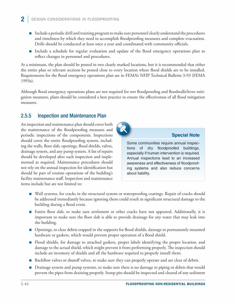
2-42 FLOODPROOFING NON-RESIDENTIAL BUILDINGS
2 DESIGN CONSIDERATIONS IN FLOODPROOFING
■■ Include a periodic drill and training program to make sure personnel clearly understand the procedures and timeliness by which they need to accomplish floodproofing measures and complete evacuation. Drills should be conducted at least once a year and coordinated with community officials.
■■ Include a schedule for regular evaluation and update of the flood emergency operations plan to reflect changes in personnel and procedures.
At a minimum, the plan should be posted in two clearly marked locations, but it is recommended that either the entire plan or relevant sections be posted close to every location where flood shields are to be installed. Requirements for the flood emergency operations plan are in FEMA’s NFIP Technical Bulletin 3-93 (FEMA 1993a).
Although flood emergency operations plans are not required for wet floodproofing and floodwalls/levee miti-gation measures, plans should be considered a best practice to ensure the effectiveness of all flood mitigation measures.
2.5.5 Inspection and Maintenance Plan
An inspection and maintenance plan should cover both the maintenance of the floodproofing measures and periodic inspections of the components. Inspections should cover the entire floodproofing system, includ-ing the walls, floor slab, openings, flood shields, valves, drainage system, and any pump system. A list of repairs should be developed after each inspection and imple-mented as required. Maintenance procedures should not rely on the annual inspection for identification but should be part of routine operations of the building’s facility maintenance staff. Inspection and maintenance items include but are not limited to:
■■ Wall systems, for cracks in the structural system or waterproofing coatings. Repair of cracks should be addressed immediately because ignoring them could result in significant structural damage to the building during a flood event.
■■ Entire floor slab, to make sure settlement or other cracks have not appeared. Additionally, it is important to make sure the floor slab is able to provide drainage for any water that may leak into the building.
■■ Openings, to clear debris trapped in the supports for flood shields, damage to permanently mounted hardware or gaskets, which would prevent proper operation of a flood shield.
■■ Flood shields, for damage to attached gaskets, proper labels identifying the proper location, and damage to the actual shield, which might prevent it from performing properly. The inspection should include an inventory of shields and all the hardware required to properly install them.
■■ Backflow valves or shutoff valves, to make sure they can properly operate and are clear of debris.
■■ Drainage system and pump systems, to make sure there is no damage to piping or debris that would prevent the pipes from draining properly. Sump pits should be inspected and cleared of any sediment
Special Note
Some communities require annual inspec-tions of dry floodproofed buildings, especially if human intervention is required. Annual inspections lead to an increased awareness and effectiveness of floodproof-ing systems and also reduce concerns about liability.
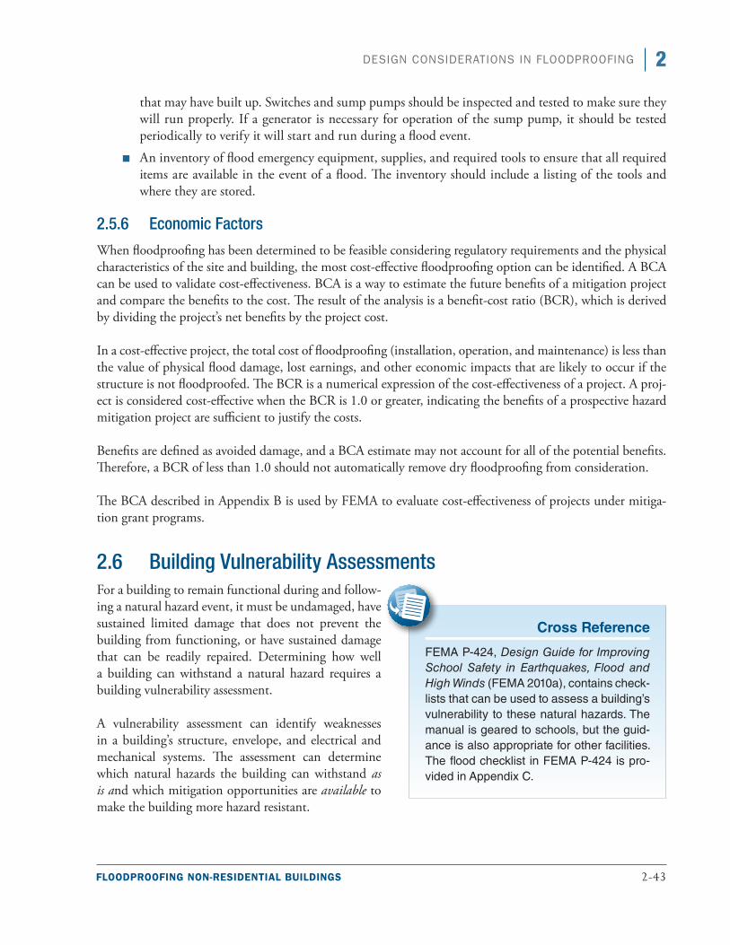
FLOODPROOFING NON-RESIDENTIAL BUILDINGS 2-43
2DESIGN CONSIDERATIONS IN FLOODPROOFING
that may have built up. Switches and sump pumps should be inspected and tested to make sure they will run properly. If a generator is necessary for operation of the sump pump, it should be tested periodically to verify it will start and run during a flood event.
■■ An inventory of flood emergency equipment, supplies, and required tools to ensure that all required items are available in the event of a flood. The inventory should include a listing of the tools and where they are stored.
2.5.6 Economic Factors
When floodproofing has been determined to be feasible considering regulatory requirements and the physical characteristics of the site and building, the most cost-effective floodproofing option can be identified. A BCA can be used to validate cost-effectiveness. BCA is a way to estimate the future benefits of a mitigation project and compare the benefits to the cost. The result of the analysis is a benefit-cost ratio (BCR), which is derived by dividing the project’s net benefits by the project cost.
In a cost-effective project, the total cost of floodproofing (installation, operation, and maintenance) is less than the value of physical flood damage, lost earnings, and other economic impacts that are likely to occur if the structure is not floodproofed. The BCR is a numerical expression of the cost-effectiveness of a project. A proj-ect is considered cost-effective when the BCR is 1.0 or greater, indicating the benefits of a prospective hazard mitigation project are sufficient to justify the costs.
Benefits are defined as avoided damage, and a BCA estimate may not account for all of the potential benefits. Therefore, a BCR of less than 1.0 should not automatically remove dry floodproofing from consideration.
The BCA described in Appendix B is used by FEMA to evaluate cost-effectiveness of projects under mitiga-tion grant programs.
2.6 Building Vulnerability AssessmentsFor a building to remain functional during and follow-ing a natural hazard event, it must be undamaged, have sustained limited damage that does not prevent the building from functioning, or have sustained damage that can be readily repaired. Determining how well a building can withstand a natural hazard requires a building vulnerability assessment.
A vulnerability assessment can identify weaknesses in a building’s structure, envelope, and electrical and mechanical systems. The assessment can determine which natural hazards the building can withstand as is and which mitigation opportunities are available to make the building more hazard resistant.
Cross Reference
FEMA P-424, Design Guide for Improving School Safety in Earthquakes, Flood and High Winds (FEMA 2010a), contains check-lists that can be used to assess a building’s vulnerability to these natural hazards. The manual is geared to schools, but the guid-ance is also appropriate for other facilities. The flood checklist in FEMA P-424 is pro-vided in Appendix C.
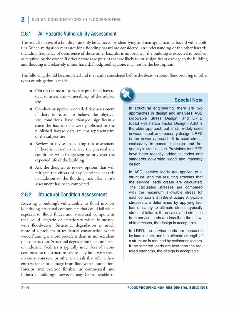
2-44 FLOODPROOFING NON-RESIDENTIAL BUILDINGS
2 DESIGN CONSIDERATIONS IN FLOODPROOFING
2.6.1 All-Hazards Vulnerability Assessment
The overall success of a building can only be achieved by identifying and managing natural hazard vulnerabili-ties. When mitigation measures for a flooding hazard are considered, an understanding of the other hazards, including frequency of occurrence of those other hazards, is important if the building is expected to perform as required by the owner. If other hazards are present that are likely to cause significant damage to the building and flooding is a relatively minor hazard, floodproofing alone may not be the best option.
The following should be completed and the results considered before the decision about floodproofing or other types of mitigation is made:
■■ Obtain the most up-to-date published hazard data to assess the vulnerability of the subject site
■■ Conduct or update a detailed risk assessment if there is reason to believe the physical site conditions have changed significantly since the hazard data were published or the published hazard data are not representative of the subject site
■■ Review or revise an existing risk assessment if there is reason to believe the physical site conditions will change significantly over the expected life of the building
■■ Ask the designer to review options that will mitigate the effects of any identified hazards in addition to the flooding risk after a risk assessment has been completed
2.6.2 Structural Condition Assessment
Assessing a building’s vulnerability to flood involves identifying structural components that could fail when exposed to flood forces and structural components that could degrade or deteriorate when inundated with floodwaters. Structural degradation is much more of a problem in residential construction where wood framing is more prevalent than in non-residen-tial construction. Structural degradation in commercial or industrial facilities is typically much less of a con-cern because the structures are usually built with steel, masonry, concrete, or other materials that offer inher-ent resistance to damage from floodwater inundation. Interior and exterior finishes in commercial and industrial buildings, however, may be vulnerable to
Special Note
In structural engineering, there are two approaches in design and analyses: ASD (Allowable Stress Design) and LRFD (Load Resistance Factor Design). ASD is the older approach but is still widely used in wood, steel, and masonry design. LRFD is the newer approach. It is used almost exclusively in concrete design and fre-quently in steel design. Provisions for LRFD have been recently added to codes and standards governing wood and masonry design.
In ASD, service loads are applied to a structure, and the resulting stresses that the service loads create are calculated. The calculated stresses are compared with the maximum allowable stress for each component in the structure. Allowable stresses are determined by applying fac-tors of safety to ultimate stress (typically stress at failure). If the calculated stresses from service loads are less than the allow-able stresses, the design is acceptable.
In LRFD, the service loads are increased by load factors, and the ultimate strength of a structure is reduced by resistance factors. If the factored loads are less than the fac-tored strengths, the design is acceptable.
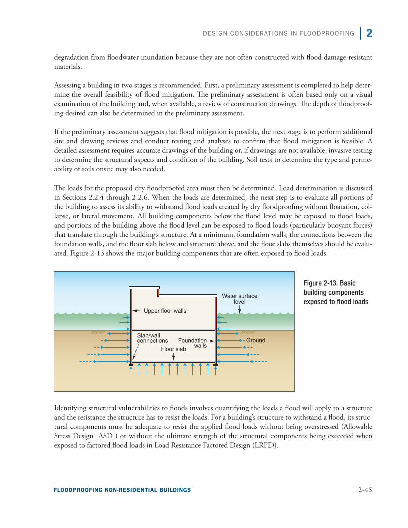
FLOODPROOFING NON-RESIDENTIAL BUILDINGS 2-45
2DESIGN CONSIDERATIONS IN FLOODPROOFING
degradation from floodwater inundation because they are not often constructed with flood damage-resistant materials.
Assessing a building in two stages is recommended. First, a preliminary assessment is completed to help deter-mine the overall feasibility of flood mitigation. The preliminary assessment is often based only on a visual examination of the building and, when available, a review of construction drawings. The depth of floodproof-ing desired can also be determined in the preliminary assessment.
If the preliminary assessment suggests that flood mitigation is possible, the next stage is to perform additional site and drawing reviews and conduct testing and analyses to confirm that flood mitigation is feasible. A detailed assessment requires accurate drawings of the building or, if drawings are not available, invasive testing to determine the structural aspects and condition of the building. Soil tests to determine the type and perme-ability of soils onsite may also needed.
The loads for the proposed dry floodproofed area must then be determined. Load determination is discussed in Sections 2.2.4 through 2.2.6. When the loads are determined, the next step is to evaluate all portions of the building to assess its ability to withstand flood loads created by dry floodproofing without floatation, col-lapse, or lateral movement. All building components below the flood level may be exposed to flood loads, and portions of the building above the flood level can be exposed to flood loads (particularly buoyant forces) that translate through the building’s structure. At a minimum, foundation walls, the connections between the foundation walls, and the floor slab below and structure above, and the floor slabs themselves should be evalu-ated. Figure 2-13 shows the major building components that are often exposed to flood loads.
Identifying structural vulnerabilities to floods involves quantifying the loads a flood will apply to a structure and the resistance the structure has to resist the loads. For a building’s structure to withstand a flood, its struc-tural components must be adequate to resist the applied flood loads without being overstressed (Allowable Stress Design [ASD]) or without the ultimate strength of the structural components being exceeded when exposed to factored flood loads in Load Resistance Factored Design (LRFD).
Figure 2-13. Basic building components exposed to flood loads
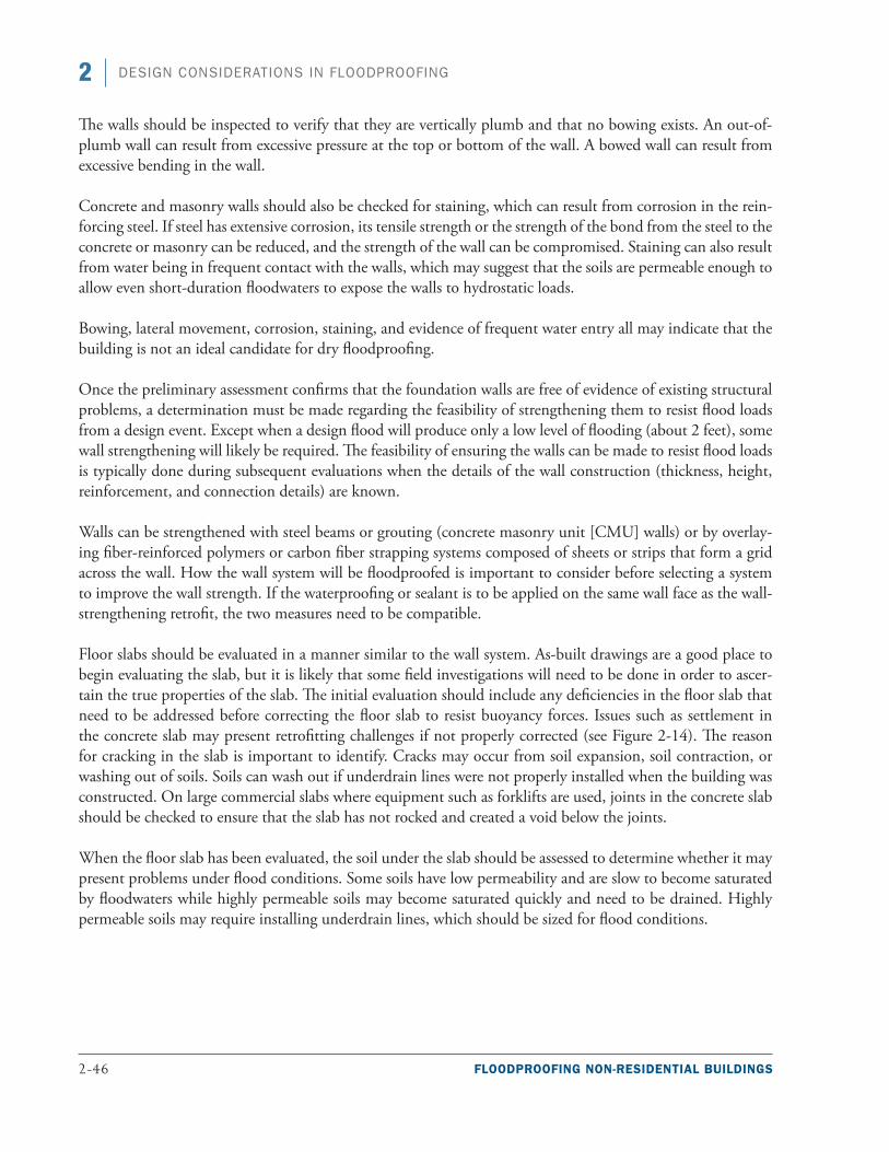
2-46 FLOODPROOFING NON-RESIDENTIAL BUILDINGS
2 DESIGN CONSIDERATIONS IN FLOODPROOFING
The walls should be inspected to verify that they are vertically plumb and that no bowing exists. An out-of-plumb wall can result from excessive pressure at the top or bottom of the wall. A bowed wall can result from excessive bending in the wall.
Concrete and masonry walls should also be checked for staining, which can result from corrosion in the rein-forcing steel. If steel has extensive corrosion, its tensile strength or the strength of the bond from the steel to the concrete or masonry can be reduced, and the strength of the wall can be compromised. Staining can also result from water being in frequent contact with the walls, which may suggest that the soils are permeable enough to allow even short-duration floodwaters to expose the walls to hydrostatic loads.
Bowing, lateral movement, corrosion, staining, and evidence of frequent water entry all may indicate that the building is not an ideal candidate for dry floodproofing.
Once the preliminary assessment confirms that the foundation walls are free of evidence of existing structural problems, a determination must be made regarding the feasibility of strengthening them to resist flood loads from a design event. Except when a design flood will produce only a low level of flooding (about 2 feet), some wall strengthening will likely be required. The feasibility of ensuring the walls can be made to resist flood loads is typically done during subsequent evaluations when the details of the wall construction (thickness, height, reinforcement, and connection details) are known.
Walls can be strengthened with steel beams or grouting (concrete masonry unit [CMU] walls) or by overlay-ing fiber-reinforced polymers or carbon fiber strapping systems composed of sheets or strips that form a grid across the wall. How the wall system will be floodproofed is important to consider before selecting a system to improve the wall strength. If the waterproofing or sealant is to be applied on the same wall face as the wall-strengthening retrofit, the two measures need to be compatible.
Floor slabs should be evaluated in a manner similar to the wall system. As-built drawings are a good place to begin evaluating the slab, but it is likely that some field investigations will need to be done in order to ascer-tain the true properties of the slab. The initial evaluation should include any deficiencies in the floor slab that need to be addressed before correcting the floor slab to resist buoyancy forces. Issues such as settlement in the concrete slab may present retrofitting challenges if not properly corrected (see Figure 2-14). The reason for cracking in the slab is important to identify. Cracks may occur from soil expansion, soil contraction, or washing out of soils. Soils can wash out if underdrain lines were not properly installed when the building was constructed. On large commercial slabs where equipment such as forklifts are used, joints in the concrete slab should be checked to ensure that the slab has not rocked and created a void below the joints.
When the floor slab has been evaluated, the soil under the slab should be assessed to determine whether it may present problems under flood conditions. Some soils have low permeability and are slow to become saturated by floodwaters while highly permeable soils may become saturated quickly and need to be drained. Highly permeable soils may require installing underdrain lines, which should be sized for flood conditions.
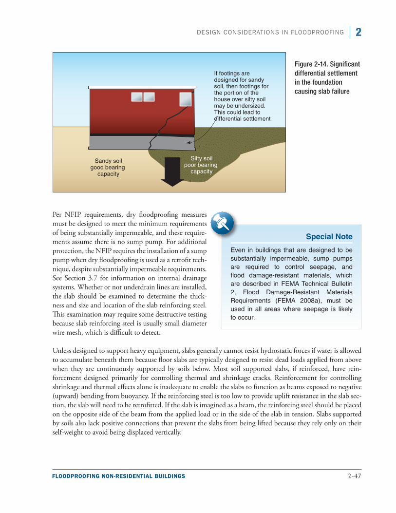
FLOODPROOFING NON-RESIDENTIAL BUILDINGS 2-47
2DESIGN CONSIDERATIONS IN FLOODPROOFING
Per NFIP requirements, dry floodproofing measures must be designed to meet the minimum requirements of being substantially impermeable, and these require-ments assume there is no sump pump. For additional protection, the NFIP requires the installation of a sump pump when dry floodproofing is used as a retrofit tech-nique, despite substantially impermeable requirements. See Section 3.7 for information on internal drainage systems. Whether or not underdrain lines are installed, the slab should be examined to determine the thick-ness and size and location of the slab reinforcing steel. This examination may require some destructive testing because slab reinforcing steel is usually small diameter wire mesh, which is difficult to detect.
Unless designed to support heavy equipment, slabs generally cannot resist hydrostatic forces if water is allowed to accumulate beneath them because floor slabs are typically designed to resist dead loads applied from above when they are continuously supported by soils below. Most soil supported slabs, if reinforced, have rein-forcement designed primarily for controlling thermal and shrinkage cracks. Reinforcement for controlling shrinkage and thermal effects alone is inadequate to enable the slabs to function as beams exposed to negative (upward) bending from buoyancy. If the reinforcing steel is too low to provide uplift resistance in the slab sec-tion, the slab will need to be retrofitted. If the slab is imagined as a beam, the reinforcing steel should be placed on the opposite side of the beam from the applied load or in the side of the slab in tension. Slabs supported by soils also lack positive connections that prevent the slabs from being lifted because they rely only on their self-weight to avoid being displaced vertically.
Figure 2-14. Significant differential settlement in the foundation causing slab failure
Special Note
Even in buildings that are designed to be substantially impermeable, sump pumps are required to control seepage, and flood damage-resistant materials, which are described in FEMA Technical Bulletin 2, Flood Damage-Resistant Materials Requirements (FEMA 2008a), must be used in all areas where seepage is likely to occur.
2-48 FLOODPROOFING NON-RESIDENTIAL BUILDINGS
2 DESIGN CONSIDERATIONS IN FLOODPROOFING
Although concrete can be added to thicken slabs (and increase their resistance to uplift strictly by increas-ing their weight), it is typically impractical to mitigate slabs to resist buoyant forces. If water can accumulate under a floor slab and installing underfloor drains cannot alleviate hydrostatic pressures acting to lift the slab, the building may not be a candidate for dry floodproofing. The only other mitigation technique that could be used to resist buoyancy on a concrete slab is to install soil anchors through the slab into the soil beneath the slab to provide upward resistance.
In addition, buoyant forces acting on submerged materials reduce their effective dead load and ability to resist uplift and overturning moments. Therefore, before dry floodproofing projects are undertaken, the overall sta-bility of a building needs to be checked to ensure that buoyant forces will not make the building unstable. The load combinations contained in Chapter 2 of ASCE 7 should be used to evaluate the stability of the dry floodproofed building.
The deficiencies in the slab and the normal use of the floodproofed area are important considerations in select-ing a retrofitting measure. If the area requires equipment to drive across the slab or maintenance crews to work in the area, maintaining a flat, unobstructed slab may be important. Similarly, maintaining the existing ceiling height may justify other retrofitting considerations.
The condition assessment should not only determine the ability of structural components to withstand flood loads, but also their impermeability. For example, basement walls between adjacent buildings should be evalu-ated for flood load resistance and impermeability. This is especially important in an urban environment or in buildings constructed in phases; otherwise, the source of flooding may become the adjacent building. Structural components, window wells, ventilation openings, and utilities (discussed in the subsequent section) can each be floodwater points of entry if not properly assessed and mitigated.
2.6.3 Vulnerability Assessments for Electrical and Mechanical Utilities and Systems
Utility and system assessments can determine how well the utilities that serve a facility and the major mechani-cal, electrical, and plumbing (MEP) systems in a facility can resist natural hazards. Although utilities and MEP systems can be damaged by high winds, seismic events, and winter storms, this discussion is focused on their vulnerability to flooding. In a discussion of system vulnerabilities, it is beneficial to distinguish utilities from systems components. Utilities are generally external to the building, while most mechanical and electrical sys-tems are internal. Although utilities themselves can be vulnerable to flooding, this document focuses primarily on the vulnerability of buildings associated with utilities when they acts as conduits and allow floodwaters to enter a building.
Utilities can be electrical or mechanical. Electrical utilities typically include power, communication (both cop-per-based and fiber-optic), and occasionally hard-wired annunciation systems such as fire alarm loops. This document focuses on electrical power utilities. Mechanical utilities include domestic water service, water ser-vice for fire suppression, steam service, and utilities to collect and dispose of sanitary sewer and storm sewer. In many municipalities, fossil fuels, namely natural gas, are also brought to buildings. Utilities can be private or municipal and can be part of a campus, which is the case when a group of buildings are supplied by a cen-tral plant.
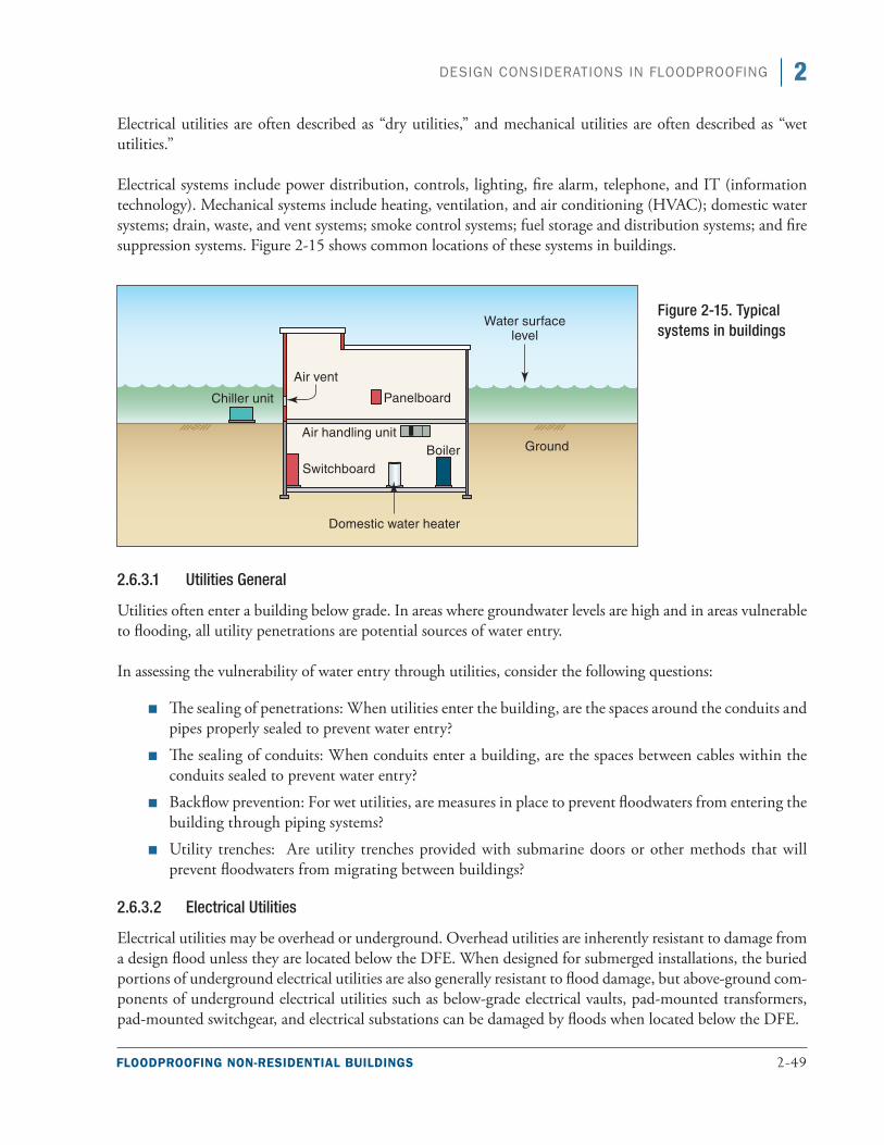
FLOODPROOFING NON-RESIDENTIAL BUILDINGS 2-49
2DESIGN CONSIDERATIONS IN FLOODPROOFING
Electrical utilities are often described as “dry utilities,” and mechanical utilities are often described as “wet utilities.”
Electrical systems include power distribution, controls, lighting, fire alarm, telephone, and IT (information technology). Mechanical systems include heating, ventilation, and air conditioning (HVAC); domestic water systems; drain, waste, and vent systems; smoke control systems; fuel storage and distribution systems; and fire suppression systems. Figure 2-15 shows common locations of these systems in buildings.
2.6.3.1 Utilities General
Utilities often enter a building below grade. In areas where groundwater levels are high and in areas vulnerable to flooding, all utility penetrations are potential sources of water entry.
In assessing the vulnerability of water entry through utilities, consider the following questions:
■■ The sealing of penetrations: When utilities enter the building, are the spaces around the conduits and pipes properly sealed to prevent water entry?
■■ The sealing of conduits: When conduits enter a building, are the spaces between cables within the conduits sealed to prevent water entry?
■■ Backflow prevention: For wet utilities, are measures in place to prevent floodwaters from entering the building through piping systems?
■■ Utility trenches: Are utility trenches provided with submarine doors or other methods that will prevent floodwaters from migrating between buildings?
2.6.3.2 Electrical Utilities
Electrical utilities may be overhead or underground. Overhead utilities are inherently resistant to damage from a design flood unless they are located below the DFE. When designed for submerged installations, the buried portions of underground electrical utilities are also generally resistant to flood damage, but above-ground com-ponents of underground electrical utilities such as below-grade electrical vaults, pad-mounted transformers, pad-mounted switchgear, and electrical substations can be damaged by floods when located below the DFE.
Figure 2-15. Typical systems in buildings
2-50 FLOODPROOFING NON-RESIDENTIAL BUILDINGS
2 DESIGN CONSIDERATIONS IN FLOODPROOFING
The following list summarizes the components of electrical utilities that may be damaged by flood inundation when located below the DFE. These components should be considered when assessing flood vulnerabilities associated with electric utilities.
■■ Electrical substations
■■ Pad-mounted transformers and other pad-mounted equipment (switchgear)
■■ Live-front electrical equipment (i.e., equipment with exposed energized terminations) in underground manholes
■■ Cable terminations and splices not designed for submerged conditions
■■ Underground transformer vaults
■■ Meter centers
■■ Electrical service equipment (switchboards in larger facilities, service panels in smaller facilities)
■■ Network interface devices for communication utilities
■■ Fire alarm master boxes below the DFE
2.6.3.3 Mechanical Utilities
Pressurized mechanical utilities such as domestic water services, fire suppression service, and fossil fuel services are generally resistant to flooding. Some vulnerability to floodwater inundation may exist in above-ground equipment such as pressure regulators and utility meters for natural gas lines. Occasionally pressurized systems rely on electrically driven pumps to maintain system pressure. These systems can become vulnerable to flood-water contamination if power is lost to electrically driven pumps. When system pressure is lost, pressurized systems are often assumed to be contaminated, and “boil water before use” orders are given until the system pressures can be restored and the systems can be decontaminated or disinfected.
Non-pressurized mechanical utilities such as gravity-draining sanitary sewers and gravity-draining storm sewers generally are not damaged by slow-moving or riverine flooding. However, they can become conduits that allow floodwaters to flow into a facility. Backflow prevention devices can reduce the potential for floodwa-ters entering facilities through non-pressurized utilities. These devices, which are essentially check valves that allow flows only in one direction, require periodic maintenance and testing to ensure they are functional and will not obstruct normal flows.
2.6.3.4 Electrical Systems
Nearly all electrical systems in a facility below the DFE are vulnerable to flooding. Electrical wiring, communi-cation equipment, fire alarm and security systems, and other electrical equipment are inherently vulnerable to inundation unless specifically designed for submerged applications, and few electrical devices used in buildings are designed to be submerged. Conduit systems should not be considered watertight, and although the exterior sheaths of some electrical cables can resist water infiltration, they should not be considered 100 percent effec-tive unless designed and installed for submerged applications. Sump pumps, underwater lighting fixtures, and some sensing devices or transducers are possible exceptions, but these devices account for only a small percent-age of the electrical equipment in a typical facility.
FLOODPROOFING NON-RESIDENTIAL BUILDINGS 2-51
2DESIGN CONSIDERATIONS IN FLOODPROOFING
2.6.3.5 Mechanical Systems
The vulnerability of mechanical systems to damage from flooding varies greatly. Pressurized piping such as domestic water systems, chilled water piping systems, and hot water piping systems can generally be exposed to flood inundation without significant damage. When flooding is saltwater flooding or when floodwaters are corrosive, piping systems may need to be cleaned to prevent degradation. In pressurized systems, pumps and controls can be damaged from floodwaters unless designed for submerged use.
Pipe insulation, particularly insulation that is not closed-cell foam, typically needs to be replaced after inunda-tion. Any pipe insulation below the DFE should be considered vulnerable to flooding unless it is closed-cell foam.
Forced-air distribution systems are particularly vulnerable to flood damage. The ducts are designed for air pres-sures that are typically measured in inches or fractions of inches of water column and cannot resist hydrostatic pressures from even small depths of floodwaters. Also, duct systems are rarely watertight, and floodwaters can enter ducts, saturate internal insulation, contaminate duct systems, and lead to the formation of molds and mildews that can significantly affect air quality. When contaminated, it is often more practical to remove and replace submerged ducts system than to try to clean them particularly with insulated duct systems. Any ducts below the DFE should be considered vulnerable to flooding.
Floodwaters may also enter exhaust vents that remove stale air from a building’s interior and intake vents that provide fresh make-up air. Water can flow into clothes dryer vents and bathroom or kitchen exhaust vents if the floodwater is higher than the exit locations on the building.
Boilers, chillers, domestic water heater, booster pumps, and HVAC controls are rarely designed for submerged installation and will be damaged by floodwater inundation.
Fuel distribution and storage systems can be vulnerable to flooding. Although fuel distribution piping is a closed pressurized system that is able to resist relatively high external and internal pressures, fuel tanks are much less so and can be damaged by floodwaters. Fuel tanks are typically designed to resist only internal pres-sures that result from the weight of the fuel stored within them and from filling operations. Tanks, unless specifically designed for submerged conditions, can fail when exposed to the external pressures that result from floodwater inundation. Tank failures can result from crushing pressures, which increase with the depth of inundation, and from anchorage failures, which increase with the amount of floodwater displaced by the tank. During Hurricane Sandy, many tanks located below grade were damaged when floodwaters filled basements. All tanks below the DFE should be considered vulnerable unless they are designed to resist crushing pressures and anchored to resist buoyancy.
In addition, fuel tanks are often located on the lowest floor of a building and pumps are installed to pump fuel to equipment, such as emergency generators, located on upper floors. When pumps are located below the DFE, they can be vulnerable to flooding. During vulnerability assessments, fuel pumps located below the DFE along with their power and control wiring should be considered vulnerable unless designed for submerged use.

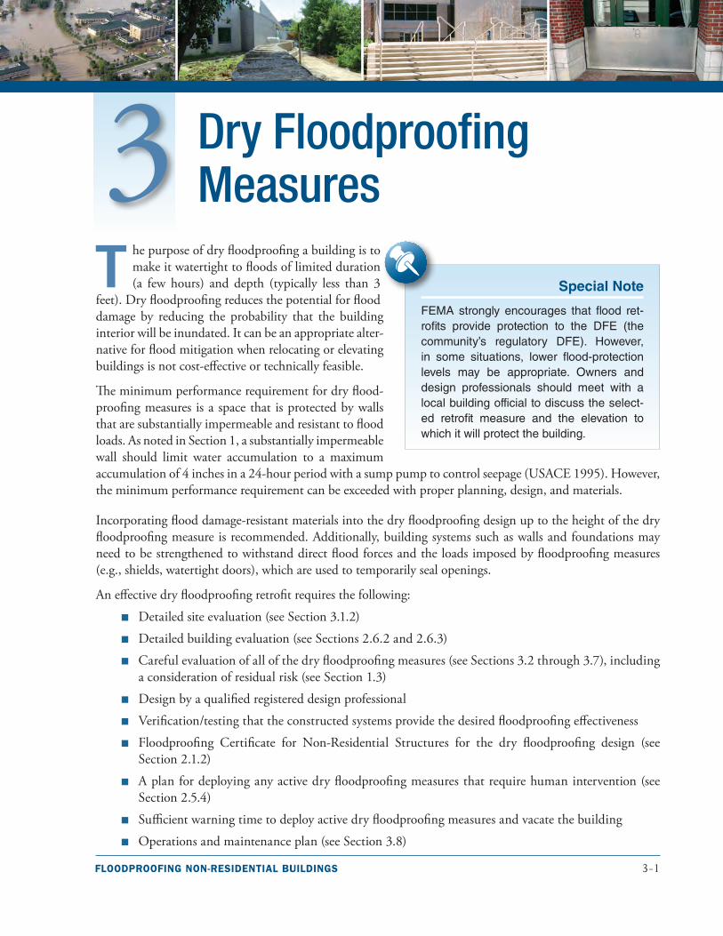
FLOODPROOFING NON-RESIDENTIAL BUILDINGS 3-1
T he purpose of dry floodproofing a building is to make it watertight to floods of limited duration (a few hours) and depth (typically less than 3
feet). Dry floodproofing reduces the potential for flood damage by reducing the probability that the building interior will be inundated. It can be an appropriate alter-native for flood mitigation when relocating or elevating buildings is not cost-effective or technically feasible.
The minimum performance requirement for dry flood-proofing measures is a space that is protected by walls that are substantially impermeable and resistant to flood loads. As noted in Section 1, a substantially impermeable wall should limit water accumulation to a maximum accumulation of 4 inches in a 24-hour period with a sump pump to control seepage (USACE 1995). However, the minimum performance requirement can be exceeded with proper planning, design, and materials.
Incorporating flood damage-resistant materials into the dry floodproofing design up to the height of the dry floodproofing measure is recommended. Additionally, building systems such as walls and foundations may need to be strengthened to withstand direct flood forces and the loads imposed by floodproofing measures (e.g., shields, watertight doors), which are used to temporarily seal openings.
An effective dry floodproofing retrofit requires the following:
■■ Detailed site evaluation (see Section 3.1.2)
■■ Detailed building evaluation (see Sections 2.6.2 and 2.6.3)
■■ Careful evaluation of all of the dry floodproofing measures (see Sections 3.2 through 3.7), including a consideration of residual risk (see Section 1.3)
■■ Design by a qualified registered design professional
■■ Verification/testing that the constructed systems provide the desired floodproofing effectiveness
■■ Floodproofing Certificate for Non-Residential Structures for the dry floodproofing design (see Section 2.1.2)
■■ A plan for deploying any active dry floodproofing measures that require human intervention (see Section 2.5.4)
■■ Sufficient warning time to deploy active dry floodproofing measures and vacate the building
■■ Operations and maintenance plan (see Section 3.8)
Dry Floodproofing Measures
Special Note
FEMA strongly encourages that flood ret-rofits provide protection to the DFE (the community’s regulatory DFE). However, in some situations, lower flood-protection levels may be appropriate. Owners and design professionals should meet with a local building official to discuss the select-ed retrofit measure and the elevation to which it will protect the building.
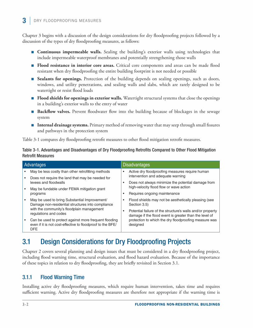
3-2 FLOODPROOFING NON-RESIDENTIAL BUILDINGS
3 DRY FLOODPROOFING MEASURES
Chapter 3 begins with a discussion of the design considerations for dry floodproofing projects followed by a discussion of the types of dry floodproofing measures, as follows:
■■ Continuous impermeable walls. Sealing the building’s exterior walls using technologies that include impermeable waterproof membranes and potentially strengthening those walls
■■ Flood resistance in interior core areas. Critical core components and areas can be made flood resistant when dry floodproofing the entire building footprint is not needed or possible
■■ Sealants for openings. Protection of the building depends on sealing openings, such as doors, windows, and utility penetrations, and sealing walls and slabs, which are rarely designed to be watertight or resist flood loads
■■ Flood shields for openings in exterior walls. Watertight structural systems that close the openings in a building’s exterior walls to the entry of water
■■ Backflow valves. Prevent floodwater flow into the building because of blockages in the sewage system
■■ Internal drainage systems. Primary method of removing water that may seep through small fissures and pathways in the protection system
Table 3-1 compares dry floodproofing retrofit measures to other flood mitigation retrofit measures.
Table 3-1. Advantages and Disadvantages of Dry Floodproofing Retrofits Compared to Other Flood Mitigation Retrofit Measures
Advantages Disadvantages■• May be less costly than other retrofitting methods
■• Does not require the land that may be needed for levees and floodwalls
■• May be fundable under FEMA mitigation grant programs
■• May be used to bring Substantial Improvement/Damage non-residential structures into compliance with the community’s floodplain management regulations and codes
■• Can be used to protect against more frequent flooding even if it is not cost-effective to floodproof to the BFE/DFE
■• Active dry floodproofing measures require human intervention and adequate warning
■• Does not always minimize the potential damage from high-velocity flood flow or wave action
■• Requires ongoing maintenance
■• Flood shields may not be aesthetically pleasing (see Section 3.5)
■• Potential failure of the structure’s walls and/or property damage if the flood event is greater than the level of protection to which the dry floodproofing measure was designed
3.1 Design Considerations for Dry Floodproofing ProjectsChapter 2 covers several planning and design issues that must be considered in a dry floodproofing project, including flood warning time, structural evaluation, and flood hazard evaluation. Because of the importance of these topics in relation to dry floodproofing, they are briefly revisited in Section 3.1.
3.1.1 Flood Warning Time
Installing active dry floodproofing measures, which require human intervention, takes time and requires sufficient warning. Active dry floodproofing measures are therefore not appropriate if the warning time is
FLOODPROOFING NON-RESIDENTIAL BUILDINGS 3-3
3DRY FLOODPROOFING MEASURES
insufficient. For example, dry floodproofing is not appropriate in areas where floodwaters are known to rapidly rise, such as where flash flooding is common, because the rapid rise in water gives little or no warning time to install active measures. See Section 2.5.3 for additional information regarding flood warning time.
Building owners should rely on the community flood warning system unless there is easy access to NWS flood predictions (such as estimates of stream gage heights) and the owner knows how to compare that information to the building elevation. A plan based on the warning time provided by community flood warning system can be developed to ensure that there will be sufficient time for:
■■ Personnel responsible for installing dry floodproofing measures to travel to the building and install the measures
■■ Proper activation of all necessary floodproofing measures, which can include installing flood gates and shields, activating sump pumps, and closing manual valves
■■ Evacuation of the building and evacuation of personnel responsible for installing the floodproofing measures before the onset of flooding
The amount of time needed to install the measures depends on available personnel and the number of steps in the installation. See Sections 2.5.4 and 3.8 for more information on what the plan should include.
3.1.2 Site and Building Evaluation
The site and building need to be evaluated to determine whether dry floodproofing is appropriate. The site investigation will determine if the existing building can be cost-effectively retrofitted by looking at flood con-ditions needed to calculate the flood loads, such as depth of flooding and flood velocity. The site investigation will also determine whether the existing soil conditions and any existing fill under or around the building could resist scour and erosion during a design flood event.
The building should be evaluated by a structural engineer to determine whether the exterior wall and floor systems can resist the forces generated by the design flood event. Flood loads can cause wall systems to fail, possibly resulting in structural damage that is more severe than damage from inundation. A primary design consideration in dry floodproofing is therefore the determination of the ability of the foundation, floor system, and exterior walls to withstand the forces generated by the design flood event. If the building strength is found to be inadequate, decisions must be made about how to achieve the desired level of performance. Options include strengthening the existing wall systems or other types of mitigation (e.g., elevation, acquisition, miti-gation reconstruction). The costs and obstacles associated with retrofitting an existing building to resist flood loads may indicate that other floodproofing measures are more appropriate. See Sections 2.4 through 2.6 for additional factors related to the site and building evaluation.
3.1.3 Building Standards and Codes
Section 2.1 covers a range of dry floodproofing regulatory requirements that vary based on which codes are in place in the project’s jurisdiction. For example, some, but not all, jurisdictions require dry floodproofing to be designed and constructed in compliance with ASCE 24. Although most of the ASCE 24 requirements outlined in Chapter 2 were developed for new construction and may be required only for Substantial Improvement/Damage, ASCE 24 requirements should be considered in all dry floodproofing projects.
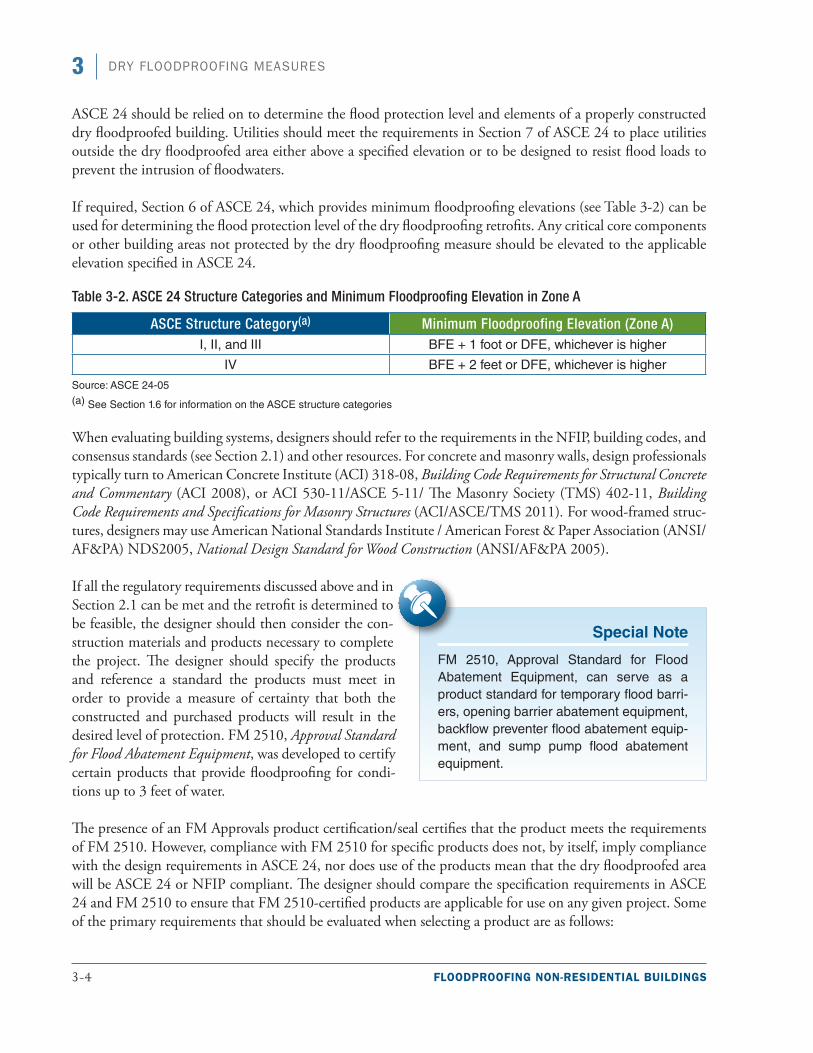
3-4 FLOODPROOFING NON-RESIDENTIAL BUILDINGS
3 DRY FLOODPROOFING MEASURES
ASCE 24 should be relied on to determine the flood protection level and elements of a properly constructed dry floodproofed building. Utilities should meet the requirements in Section 7 of ASCE 24 to place utilities outside the dry floodproofed area either above a specified elevation or to be designed to resist flood loads to prevent the intrusion of floodwaters.
If required, Section 6 of ASCE 24, which provides minimum floodproofing elevations (see Table 3-2) can be used for determining the flood protection level of the dry floodproofing retrofits. Any critical core components or other building areas not protected by the dry floodproofing measure should be elevated to the applicable elevation specified in ASCE 24.
Table 3-2. ASCE 24 Structure Categories and Minimum Floodproofing Elevation in Zone A
ASCE Structure Category(a) Minimum Floodproofing Elevation (Zone A)I, II, and III BFE + 1 foot or DFE, whichever is higher
IV BFE + 2 feet or DFE, whichever is higher
Source: ASCE 24-05(a) See Section 1.6 for information on the ASCE structure categories
When evaluating building systems, designers should refer to the requirements in the NFIP, building codes, and consensus standards (see Section 2.1) and other resources. For concrete and masonry walls, design professionals typically turn to American Concrete Institute (ACI) 318-08, Building Code Requirements for Structural Concrete and Commentary (ACI 2008), or ACI 530-11/ASCE 5-11/ The Masonry Society (TMS) 402-11, Building Code Requirements and Specifications for Masonry Structures (ACI/ASCE/TMS 2011). For wood-framed struc-tures, designers may use American National Standards Institute / American Forest & Paper Association (ANSI/AF&PA) NDS2005, National Design Standard for Wood Construction (ANSI/AF&PA 2005).
If all the regulatory requirements discussed above and in Section 2.1 can be met and the retrofit is determined to be feasible, the designer should then consider the con-struction materials and products necessary to complete the project. The designer should specify the products and reference a standard the products must meet in order to provide a measure of certainty that both the constructed and purchased products will result in the desired level of protection. FM 2510, Approval Standard for Flood Abatement Equipment, was developed to certify certain products that provide floodproofing for condi-tions up to 3 feet of water.
The presence of an FM Approvals product certification/seal certifies that the product meets the requirements of FM 2510. However, compliance with FM 2510 for specific products does not, by itself, imply compliance with the design requirements in ASCE 24, nor does use of the products mean that the dry floodproofed area will be ASCE 24 or NFIP compliant. The designer should compare the specification requirements in ASCE 24 and FM 2510 to ensure that FM 2510-certified products are applicable for use on any given project. Some of the primary requirements that should be evaluated when selecting a product are as follows:
Special Note
FM 2510, Approval Standard for Flood Abatement Equipment, can serve as a product standard for temporary flood barri-ers, opening barrier abatement equipment, backflow preventer flood abatement equip-ment, and sump pump flood abatement equipment.
FLOODPROOFING NON-RESIDENTIAL BUILDINGS 3-5
3DRY FLOODPROOFING MEASURES
■■ Hydrostatic loads
■■ Hydrodynamic loads
■■ Wave loads
■■ Buoyancy requirements
■■ Debris impact loads
■■ Leakage
■■ Installation requirements
■■ Requirements related to material exposure
3.1.4 Verification and Testing of Systems
An often overlooked part of the design process deciding on a testing method for the effectiveness of the dry floodproofing. During the construction phase of the project, as wall systems are being retrofitted and installed, it is important to test them to verify that they can resist hydrostatic loads and the components are indeed waterproof. While some projects may protect such valuable resources that large-scale testing is cost-effective, in other situations, the testing of individual components such as flood shields protecting doors may be all that is necessary. Large-scale tests have entailed constructing large barriers around the outside of buildings and the area immediately around the building being flooded for a few hours. Smaller-scale tests may only require small barriers or forms to be constructed around individual components and those areas filled with water. The main reason for any type of test is ensure the designed hydrostatic load is achieved. The area must be filled with water to the designed flood protection level to develop the necessary hydrostatic load. Testing allows leaks to be identified under a controlled process and addressed prior to the completion of construction. However, designers and owners should bear in mind that these tests will only test the system for hydrostatic loads for a specific duration. Other loading factors such as buoyancy loads or the impacts of long duration flooding may be difficult or impossible to test.
3.2 Continuous Impermeable WallsA continuous impermeable wall is substantially impermeable to the passage of water, and the structural com-ponents of the wall are capable of resisting hydrostatic and hydrodynamic loads and the effects of buoyancy. Two resources for dry floodproofing building wall assemblies to create continuous impermeable walls are Flood Proofing Tests: Tests of Materials and Systems for Flood Proofing Structures (USACE 1988) and the Southeast Region Research Initiative’s (SERRI) Floodproof Construction: Working for Coastal Communities (ORNL 2011), referred to as the SERRI Report.
The designer should review the USACE report (which recommends dry floodproofing in many cases up to 3 feet) to determine whether the recommendations are consistent with the walls in the retrofit project. The USACE report contains information on tested systems and observed deflections. The SERRI Report focuses on new construction but may provide the designer with some ideas of building assemblies that proved to be impermeable in that research.
After the primary wall system and foundation have been strengthened to resist flood loads (if necessary), the building must be sealed and other portions of the building (e.g., windows, doors, utility points of entry)
3-6 FLOODPROOFING NON-RESIDENTIAL BUILDINGS
3 DRY FLOODPROOFING MEASURES
must be evaluated to determine how best to prevent floodwaters from entering the enclosed area. The three categories of measures that can contribute to making the primary wall system impermeable are protecting openings (closing, sealing, or shielding), waterproofing the walls, and using a flood wrapping system.
In some instances, it may be more cost-effective or less invasive to building occupants during the retrofit pro-cess to construct a continuous impermeable wall on the outside of the existing wall system. Some wall systems, such as steel stud wall systems, may be too difficult to make impermeable, and in those instances a new wall system may be constructed along the perimeter of the existing wall to provide protection. In these instances, the load path to the foundation may be a primary concern for the designer.
3.2.1 Openings
The designer and owner should consider permanently closing any openings in the building’s exterior if doing so would be inconsequential to functional use. Although filling in openings may affect the original or normal use of the building, filled openings limit the number of areas that require human intervention before a flood event. Openings similar to the one shown in Figure 3-1 must be evaluated individually in order to properly tie in the retrofit to the existing wall system and prevent a potential weak spot. Filled openings should be con-structed so they match the full thickness of the wall system and are anchored properly into the surrounding wall system.
Permanently filling openings can be used in conjunction with deployable flood shields, which protect the remaining openings in exterior walls. Flood shields are used to temporarily seal openings from incoming flood-waters (see Section 3.5 for more information on flood shields).
Special Note
The SERRI Report describes several wall assemblies including sealed CMU walls, cavity walls, unsealed CMU walls, Insulated Concrete Form Walls, metal stud walls, Structural Insulated Panel walls, sheet membranes over CMU walls, and a waterproof coating on a CMU wall. The report is available at: http://www.serri.org/publications/Pages/Reports.aspx.
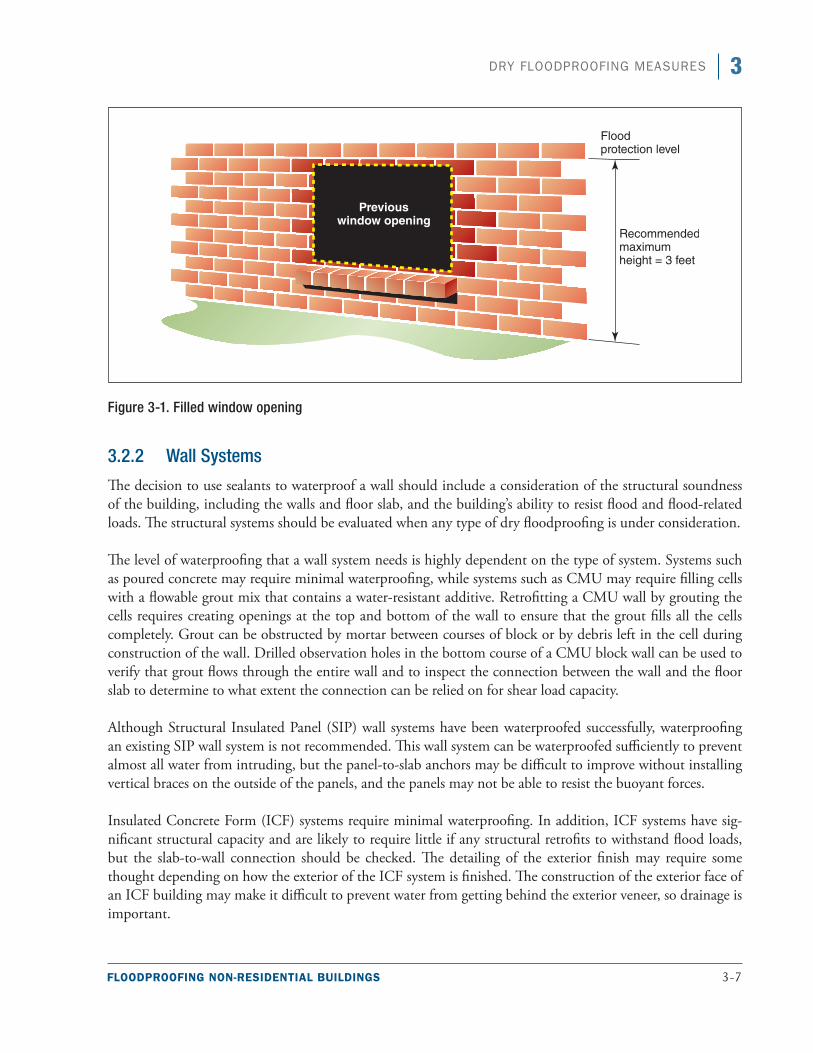
FLOODPROOFING NON-RESIDENTIAL BUILDINGS 3-7
3DRY FLOODPROOFING MEASURES
Figure 3-1. Filled window opening
3.2.2 Wall Systems
The decision to use sealants to waterproof a wall should include a consideration of the structural soundness of the building, including the walls and floor slab, and the building’s ability to resist flood and flood-related loads. The structural systems should be evaluated when any type of dry floodproofing is under consideration.
The level of waterproofing that a wall system needs is highly dependent on the type of system. Systems such as poured concrete may require minimal waterproofing, while systems such as CMU may require filling cells with a flowable grout mix that contains a water-resistant additive. Retrofitting a CMU wall by grouting the cells requires creating openings at the top and bottom of the wall to ensure that the grout fills all the cells completely. Grout can be obstructed by mortar between courses of block or by debris left in the cell during construction of the wall. Drilled observation holes in the bottom course of a CMU block wall can be used to verify that grout flows through the entire wall and to inspect the connection between the wall and the floor slab to determine to what extent the connection can be relied on for shear load capacity.
Although Structural Insulated Panel (SIP) wall systems have been waterproofed successfully, waterproofing an existing SIP wall system is not recommended. This wall system can be waterproofed sufficiently to prevent almost all water from intruding, but the panel-to-slab anchors may be difficult to improve without installing vertical braces on the outside of the panels, and the panels may not be able to resist the buoyant forces.
Insulated Concrete Form (ICF) systems require minimal waterproofing. In addition, ICF systems have sig-nificant structural capacity and are likely to require little if any structural retrofits to withstand flood loads, but the slab-to-wall connection should be checked. The detailing of the exterior finish may require some thought depending on how the exterior of the ICF system is finished. The construction of the exterior face of an ICF building may make it difficult to prevent water from getting behind the exterior veneer, so drainage is important.
Previouswindow opening
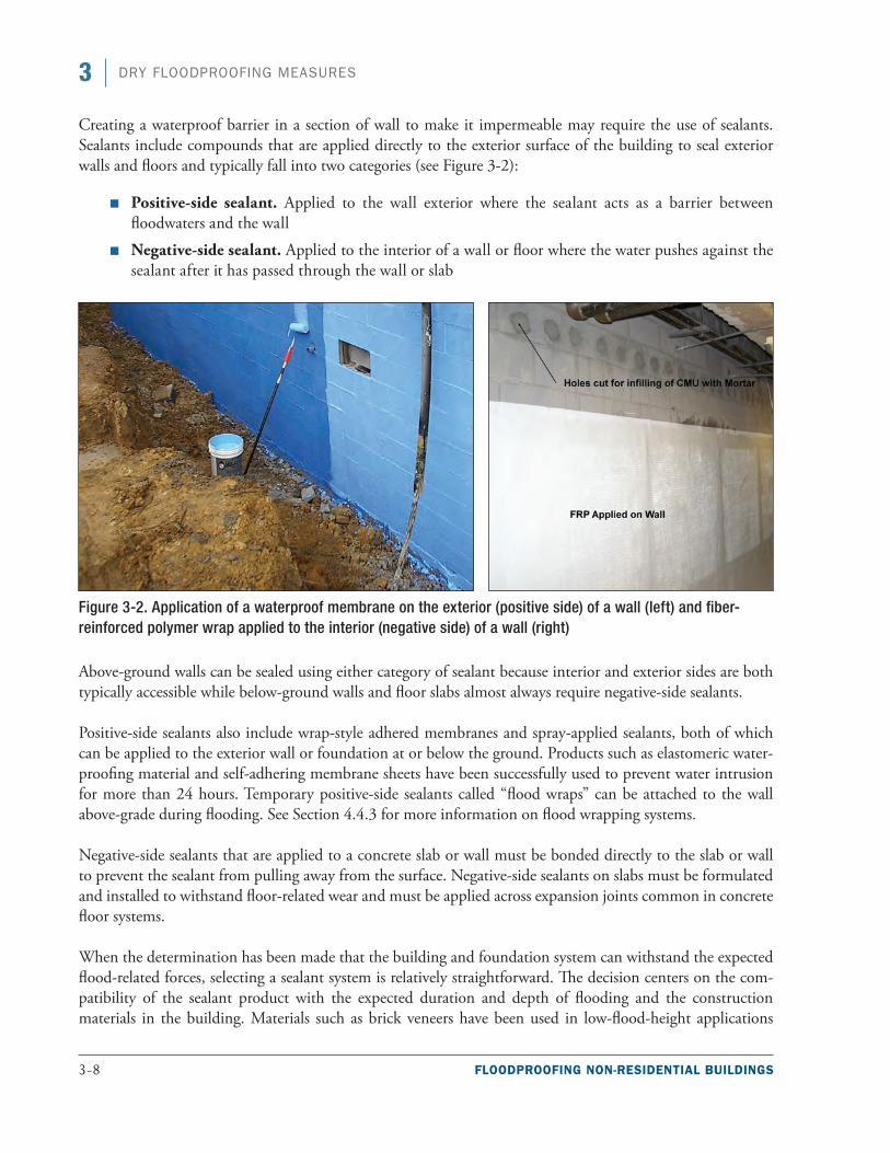
3-8 FLOODPROOFING NON-RESIDENTIAL BUILDINGS
3 DRY FLOODPROOFING MEASURES
Creating a waterproof barrier in a section of wall to make it impermeable may require the use of sealants. Sealants include compounds that are applied directly to the exterior surface of the building to seal exterior walls and floors and typically fall into two categories (see Figure 3-2):
■■ Positive-side sealant. Applied to the wall exterior where the sealant acts as a barrier between floodwaters and the wall
■■ Negative-side sealant. Applied to the interior of a wall or floor where the water pushes against the sealant after it has passed through the wall or slab
Figure 3-2. Application of a waterproof membrane on the exterior (positive side) of a wall (left) and fiber-reinforced polymer wrap applied to the interior (negative side) of a wall (right)
Above-ground walls can be sealed using either category of sealant because interior and exterior sides are both typically accessible while below-ground walls and floor slabs almost always require negative-side sealants.
Positive-side sealants also include wrap-style adhered membranes and spray-applied sealants, both of which can be applied to the exterior wall or foundation at or below the ground. Products such as elastomeric water-proofing material and self-adhering membrane sheets have been successfully used to prevent water intrusion for more than 24 hours. Temporary positive-side sealants called “flood wraps” can be attached to the wall above-grade during flooding. See Section 4.4.3 for more information on flood wrapping systems.
Negative-side sealants that are applied to a concrete slab or wall must be bonded directly to the slab or wall to prevent the sealant from pulling away from the surface. Negative-side sealants on slabs must be formulated and installed to withstand floor-related wear and must be applied across expansion joints common in concrete floor systems.
When the determination has been made that the building and foundation system can withstand the expected flood-related forces, selecting a sealant system is relatively straightforward. The decision centers on the com-patibility of the sealant product with the expected duration and depth of flooding and the construction materials in the building. Materials such as brick veneers have been used in low-flood-height applications
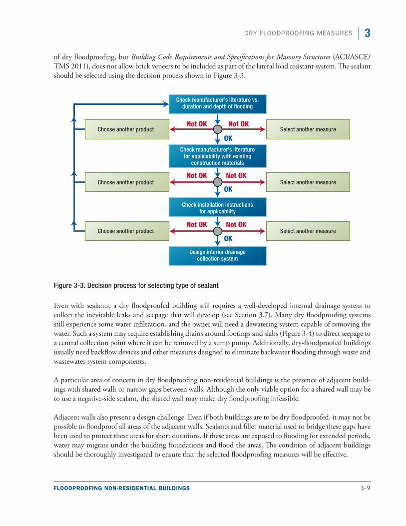
FLOODPROOFING NON-RESIDENTIAL BUILDINGS 3-9
3DRY FLOODPROOFING MEASURES
of dry floodproofing, but Building Code Requirements and Specifications for Masonry Structures (ACI/ASCE/TMS 2011), does not allow brick veneers to be included as part of the lateral load resistant system. The sealant should be selected using the decision process shown in Figure 3-3.
Figure 3-3. Decision process for selecting type of sealant
Even with sealants, a dry floodproofed building still requires a well-developed internal drainage system to collect the inevitable leaks and seepage that will develop (see Section 3.7). Many dry floodproofing systems still experience some water infiltration, and the owner will need a dewatering system capable of removing the water. Such a system may require establishing drains around footings and slabs (Figure 3-4) to direct seepage to a central collection point where it can be removed by a sump pump. Additionally, dry-floodproofed buildings usually need backflow devices and other measures designed to eliminate backwater flooding through waste and wastewater system components.
A particular area of concern in dry floodproofing non-residential buildings is the presence of adjacent build-ings with shared walls or narrow gaps between walls. Although the only viable option for a shared wall may be to use a negative-side sealant, the shared wall may make dry floodproofing infeasible.
Adjacent walls also present a design challenge. Even if both buildings are to be dry floodproofed, it may not be possible to floodproof all areas of the adjacent walls. Sealants and filler material used to bridge these gaps have been used to protect these areas for short durations. If these areas are exposed to flooding for extended periods, water may migrate under the building foundations and flood the areas. The condition of adjacent buildings should be thoroughly investigated to ensure that the selected floodproofing measures will be effective.
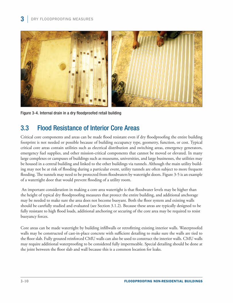
3-10 FLOODPROOFING NON-RESIDENTIAL BUILDINGS
3 DRY FLOODPROOFING MEASURES
Figure 3-4. Internal drain in a dry floodproofed retail building
3.3 Flood Resistance of Interior Core AreasCritical core components and areas can be made flood resistant even if dry floodproofing the entire building footprint is not needed or possible because of building occupancy type, geometry, function, or cost. Typical critical core areas contain utilities such as electrical distribution and switching areas, emergency generators, emergency fuel supplies, and other mission-critical components that cannot be moved or elevated. In many large complexes or campuses of buildings such as museums, universities, and large businesses, the utilities may be housed in a central building and linked to the other buildings via tunnels. Although the main utility build-ing may not be at risk of flooding during a particular event, utility tunnels are often subject to more frequent flooding. The tunnels may need to be protected from floodwaters by watertight doors. Figure 3-5 is an example of a watertight door that would prevent flooding of a utility room.
An important consideration in making a core area watertight is that floodwater levels may be higher than the height of typical dry floodproofing measures that protect the entire building, and additional anchorage may be needed to make sure the area does not become buoyant. Both the floor system and existing walls should be carefully studied and evaluated (see Section 3.1.2). Because these areas are typically designed to be fully resistant to high flood loads, additional anchoring or securing of the core area may be required to resist buoyancy forces.
Core areas can be made watertight by building infillwalls or retrofitting existing interior walls. Waterproofed walls may be constructed of cast-in-place concrete with sufficient detailing to make sure the walls are tied to the floor slab. Fully grouted reinforced CMU walls can also be used to construct the interior walls. CMU walls may require additional waterproofing to be considered fully impermeable. Special detailing should be done at the joint between the floor slab and wall because this is a common location for leaks.
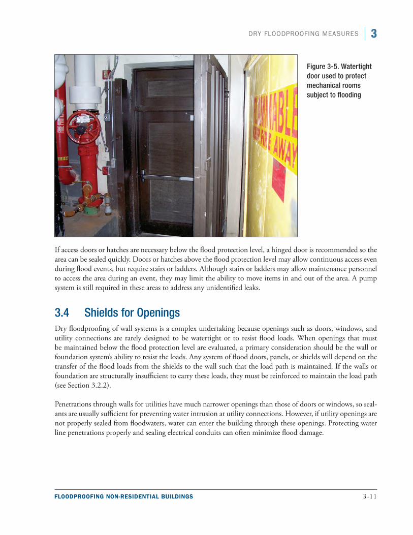
FLOODPROOFING NON-RESIDENTIAL BUILDINGS 3-11
3DRY FLOODPROOFING MEASURES
If access doors or hatches are necessary below the flood protection level, a hinged door is recommended so the area can be sealed quickly. Doors or hatches above the flood protection level may allow continuous access even during flood events, but require stairs or ladders. Although stairs or ladders may allow maintenance personnel to access the area during an event, they may limit the ability to move items in and out of the area. A pump system is still required in these areas to address any unidentified leaks.
3.4 Shields for OpeningsDry floodproofing of wall systems is a complex undertaking because openings such as doors, windows, and utility connections are rarely designed to be watertight or to resist flood loads. When openings that must be maintained below the flood protection level are evaluated, a primary consideration should be the wall or foundation system’s ability to resist the loads. Any system of flood doors, panels, or shields will depend on the transfer of the flood loads from the shields to the wall such that the load path is maintained. If the walls or foundation are structurally insufficient to carry these loads, they must be reinforced to maintain the load path (see Section 3.2.2).
Penetrations through walls for utilities have much narrower openings than those of doors or windows, so seal-ants are usually sufficient for preventing water intrusion at utility connections. However, if utility openings are not properly sealed from floodwaters, water can enter the building through these openings. Protecting water line penetrations properly and sealing electrical conduits can often minimize flood damage.
Figure 3-5. Watertight door used to protect mechanical rooms subject to flooding
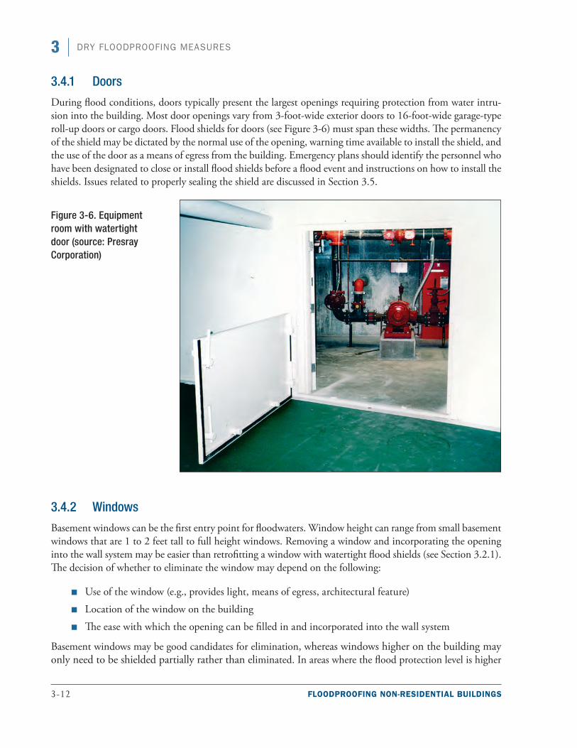
3-12 FLOODPROOFING NON-RESIDENTIAL BUILDINGS
3 DRY FLOODPROOFING MEASURES
3.4.1 Doors
During flood conditions, doors typically present the largest openings requiring protection from water intru-sion into the building. Most door openings vary from 3-foot-wide exterior doors to 16-foot-wide garage-type roll-up doors or cargo doors. Flood shields for doors (see Figure 3-6) must span these widths. The permanency of the shield may be dictated by the normal use of the opening, warning time available to install the shield, and the use of the door as a means of egress from the building. Emergency plans should identify the personnel who have been designated to close or install flood shields before a flood event and instructions on how to install the shields. Issues related to properly sealing the shield are discussed in Section 3.5.
3.4.2 Windows
Basement windows can be the first entry point for floodwaters. Window height can range from small basement windows that are 1 to 2 feet tall to full height windows. Removing a window and incorporating the opening into the wall system may be easier than retrofitting a window with watertight flood shields (see Section 3.2.1). The decision of whether to eliminate the window may depend on the following:
■■ Use of the window (e.g., provides light, means of egress, architectural feature)
■■ Location of the window on the building
■■ The ease with which the opening can be filled in and incorporated into the wall system
Basement windows may be good candidates for elimination, whereas windows higher on the building may only need to be shielded partially rather than eliminated. In areas where the flood protection level is higher
Figure 3-6. Equipment room with watertight door (source: Presray Corporation)
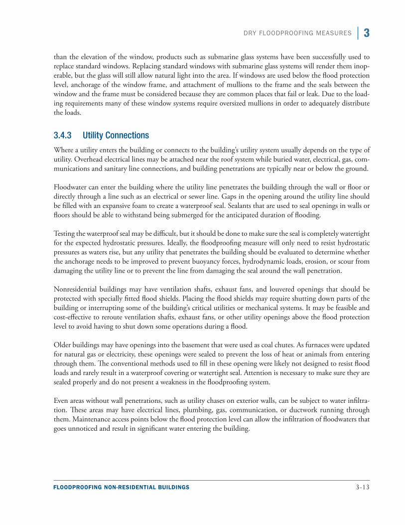
FLOODPROOFING NON-RESIDENTIAL BUILDINGS 3-13
3DRY FLOODPROOFING MEASURES
than the elevation of the window, products such as submarine glass systems have been successfully used to replace standard windows. Replacing standard windows with submarine glass systems will render them inop-erable, but the glass will still allow natural light into the area. If windows are used below the flood protection level, anchorage of the window frame, and attachment of mullions to the frame and the seals between the window and the frame must be considered because they are common places that fail or leak. Due to the load-ing requirements many of these window systems require oversized mullions in order to adequately distribute the loads.
3.4.3 Utility Connections
Where a utility enters the building or connects to the building’s utility system usually depends on the type of utility. Overhead electrical lines may be attached near the roof system while buried water, electrical, gas, com-munications and sanitary line connections, and building penetrations are typically near or below the ground.
Floodwater can enter the building where the utility line penetrates the building through the wall or floor or directly through a line such as an electrical or sewer line. Gaps in the opening around the utility line should be filled with an expansive foam to create a waterproof seal. Sealants that are used to seal openings in walls or floors should be able to withstand being submerged for the anticipated duration of flooding.
Testing the waterproof seal may be difficult, but it should be done to make sure the seal is completely watertight for the expected hydrostatic pressures. Ideally, the floodproofing measure will only need to resist hydrostatic pressures as waters rise, but any utility that penetrates the building should be evaluated to determine whether the anchorage needs to be improved to prevent buoyancy forces, hydrodynamic loads, erosion, or scour from damaging the utility line or to prevent the line from damaging the seal around the wall penetration.
Nonresidential buildings may have ventilation shafts, exhaust fans, and louvered openings that should be protected with specially fitted flood shields. Placing the flood shields may require shutting down parts of the building or interrupting some of the building’s critical utilities or mechanical systems. It may be feasible and cost-effective to reroute ventilation shafts, exhaust fans, or other utility openings above the flood protection level to avoid having to shut down some operations during a flood.
Older buildings may have openings into the basement that were used as coal chutes. As furnaces were updated for natural gas or electricity, these openings were sealed to prevent the loss of heat or animals from entering through them. The conventional methods used to fill in these opening were likely not designed to resist flood loads and rarely result in a waterproof covering or watertight seal. Attention is necessary to make sure they are sealed properly and do not present a weakness in the floodproofing system.
Even areas without wall penetrations, such as utility chases on exterior walls, can be subject to water infiltra-tion. These areas may have electrical lines, plumbing, gas, communication, or ductwork running through them. Maintenance access points below the flood protection level can allow the infiltration of floodwaters that goes unnoticed and result in significant water entering the building.
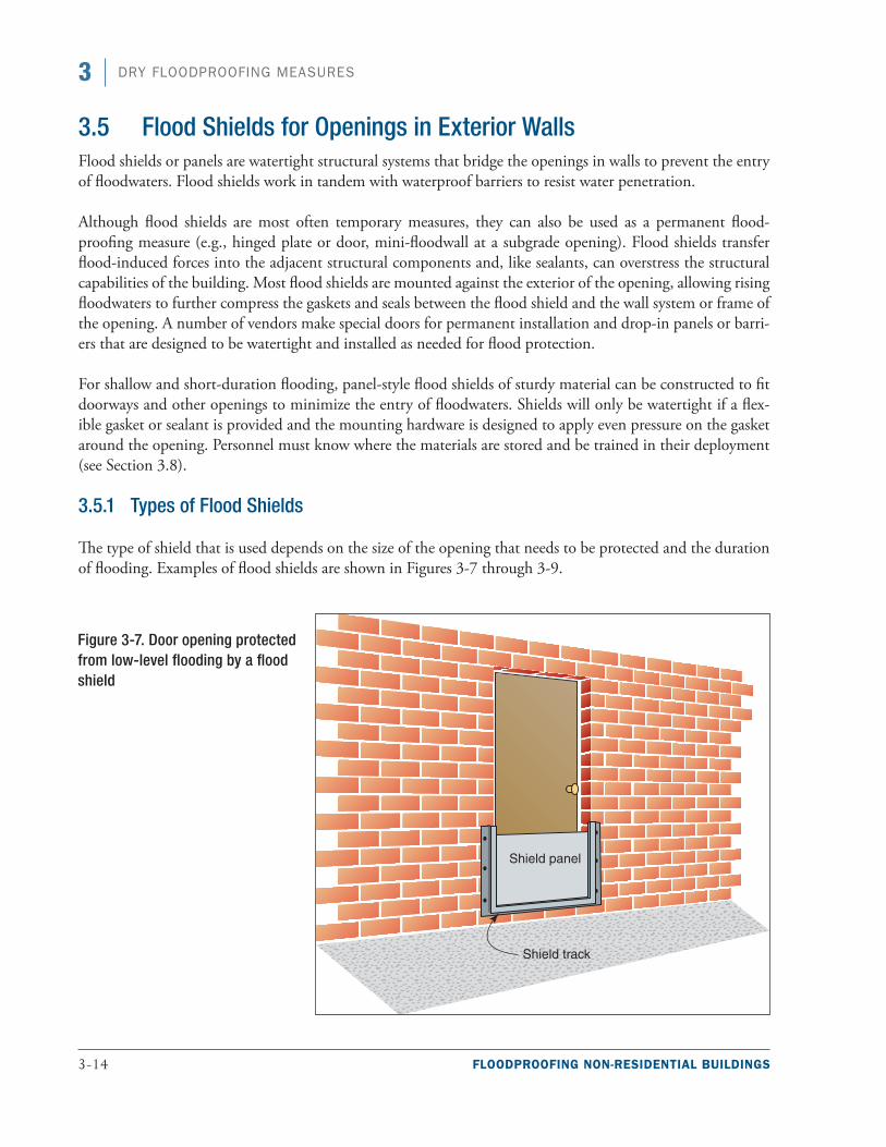
3-14 FLOODPROOFING NON-RESIDENTIAL BUILDINGS
3 DRY FLOODPROOFING MEASURES
3.5 Flood Shields for Openings in Exterior Walls Flood shields or panels are watertight structural systems that bridge the openings in walls to prevent the entry of floodwaters. Flood shields work in tandem with waterproof barriers to resist water penetration.
Although flood shields are most often temporary measures, they can also be used as a permanent flood-proofing measure (e.g., hinged plate or door, mini-floodwall at a subgrade opening). Flood shields transfer flood-induced forces into the adjacent structural components and, like sealants, can overstress the structural capabilities of the building. Most flood shields are mounted against the exterior of the opening, allowing rising floodwaters to further compress the gaskets and seals between the flood shield and the wall system or frame of the opening. A number of vendors make special doors for permanent installation and drop-in panels or barri-ers that are designed to be watertight and installed as needed for flood protection.
For shallow and short-duration flooding, panel-style flood shields of sturdy material can be constructed to fit doorways and other openings to minimize the entry of floodwaters. Shields will only be watertight if a flex-ible gasket or sealant is provided and the mounting hardware is designed to apply even pressure on the gasket around the opening. Personnel must know where the materials are stored and be trained in their deployment (see Section 3.8).
3.5.1 Types of Flood Shields
The type of shield that is used depends on the size of the opening that needs to be protected and the duration of flooding. Examples of flood shields are shown in Figures 3-7 through 3-9.
Figure 3-7. Door opening protected from low-level flooding by a flood shield
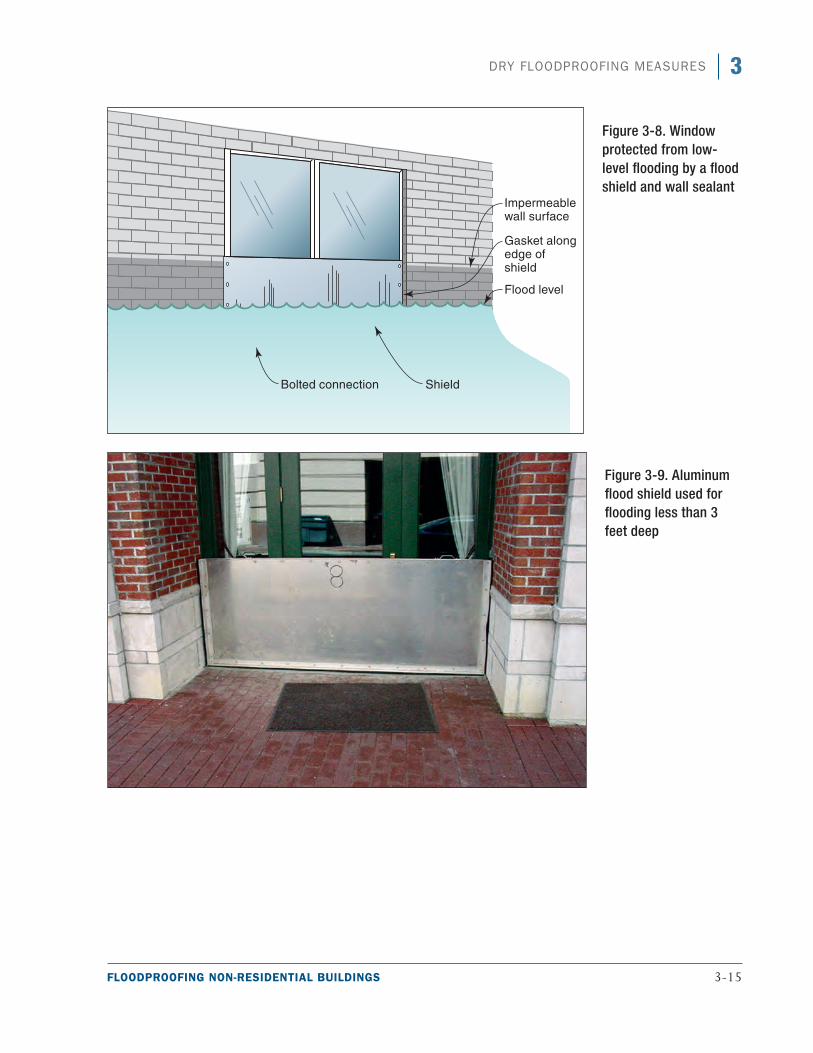
FLOODPROOFING NON-RESIDENTIAL BUILDINGS 3-15
3DRY FLOODPROOFING MEASURES
Figure 3-8. Window protected from low-level flooding by a flood shield and wall sealant
Figure 3-9. Aluminum flood shield used for flooding less than 3 feet deep
3-16 FLOODPROOFING NON-RESIDENTIAL BUILDINGS
3 DRY FLOODPROOFING MEASURES
As noted above, longer and larger flood shields, such as for vehicle entrances, are normally constructed of steel plate or heavy aluminum plate. Because of the weight of the shield, it is usually best for the shield to be hinged so that it can swing into place (see Figure 3-10). Hinging can be along the bottom so the shield lies flat when not in use, or it can be placed along one side so the shield can fold back out of the way. Shields hinged on the bottom must fold into a recess so the surface of the entrance is smooth. Shields that fold into a recess require a design to make the shields and recess able to withstand the weight of the traffic over them. In addition, below-grade recesses can fill with water and debris, which increases maintenance and hinders rapid deployment.
Hinged and sliding flood shields (see Figure 3-10) only require the user to unlock and rotate or slide the flood shield and lock it into place. These flood shields may include pedestrian doors that are full-height doors with complex latching mechanisms for higher flood heights or lower half-door systems. Although hinged flood shields require human intervention, they can often be deployed by one person. Room must be available for the systems to swing or slide either beside or above the door when not in use.
Heavy flood shields for larger openings may require electrical or mechanical systems to move them into place. Designs should include a consideration of the fact that power may not be available following the event and that access through the opening may be necessary to restore power.
Passive (automatic) flood shields (see Figure 3-10) may be preferred to active flood shields, which require human intervention. Passive flood shields allow openings to be used until floodwaters reach a certain height. Rising floodwaters use a ballast system to push the flood shield closed. Ballast systems can be used in dry floodproofing and floodwalls when large shields are difficult to install quickly. Passive flood shield systems may require room under the opening to allow the flood shield to be stored when it is not in use.
Flood shields that must be moved into position prior to a flood event require the most time critical and labor intensive human intervention of any dry floodproofing measure. Although shield systems may be the most aes-thetically pleasing, more than one person may be needed to carry and install them. A plan is needed to ensure that they will be installed efficiently, and the installers may need to have extensive training on proper installa-tion (see Section 3.8).
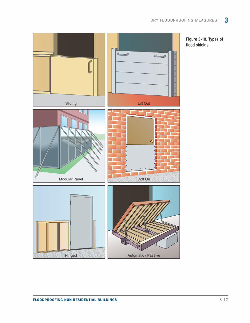
FLOODPROOFING NON-RESIDENTIAL BUILDINGS 3-17
3DRY FLOODPROOFING MEASURES
Figure 3-10. Types of flood shields
3-18 FLOODPROOFING NON-RESIDENTIAL BUILDINGS
3 DRY FLOODPROOFING MEASURES
3.5.2 Flood Shield Materials
Considerations such as the size of the opening to be protected, the normal use of the openings, who will install the flood shields, and how quickly after the floodwaters recede the openings need to be available are important in determining the material to be used and also how the flood shield will be attached to the structure.
Steel, aluminum, and, in limited applications, marine-grade plywood are some of the materials that are used to fabricate shields, depending on loads.
For normal sized openings such as entrance doors, aluminum is probably the most common material. It is lightweight, allowing for easy fabrication and transport, and is resistant to corrosion. However, aluminum can buckle under large hydrostatic pressures, so additional reinforcement may be required. Shields designed for long-duration flooding are typically steel or aluminum.
For smaller openings such as windows with short-duration shallow flooding, marine-grade plywood is also commonly used. However, plywood is subject to warping if not properly stored. In addition, it will collapse under relatively low flood forces and usually requires significant reinforcement, which is usually some type of wood frame. Plywood flood shields are limited to short spans and low water heights. In addition, most plywood deteriorates when exposed to high moisture. Therefore, plywood flood shields should be examined periodically and replaced as necessary.
Longer and larger flood shields, such as for vehicle entrances, must be able to withstand significant flood forces and should therefore be constructed of a substantial material. This material is normally steel plate, which is protected against rust and corrosion. Heavy aluminum plate may also be used, although it will likely need to be reinforced.
3.5.3 Gasket and Seals
When leaks do occur into a dry floodproofed area, gaskets and seals are often the primary source. Flood shields depend on a variety of gasket and seal materials and configurations to prevent water intrusion. Pneumatic seals have been used successfully on some systems, but they rely on maintaining air pressure to prevent water from leaking past them. In long-duration flooding, it may not be possible to refill or maintain pneumatic seals. Self-sealing compression seals are more reliable and can be used in conjunction with pneumatic seals for a redundant configuration, which provides more protection.
Seals and gaskets can be monitored during a flood event by moisture monitors (e.g., water sensor, camera) inside the flood shield, and maintenance personnel can be notified of any leaks.
Seals and gaskets are subject to cracking or rot and need to be repaired or replaced periodically to be an effective watertight seal under flood conditions. Storage of flood shields and components outside can cause premature deterioration of seals and gasket materials.
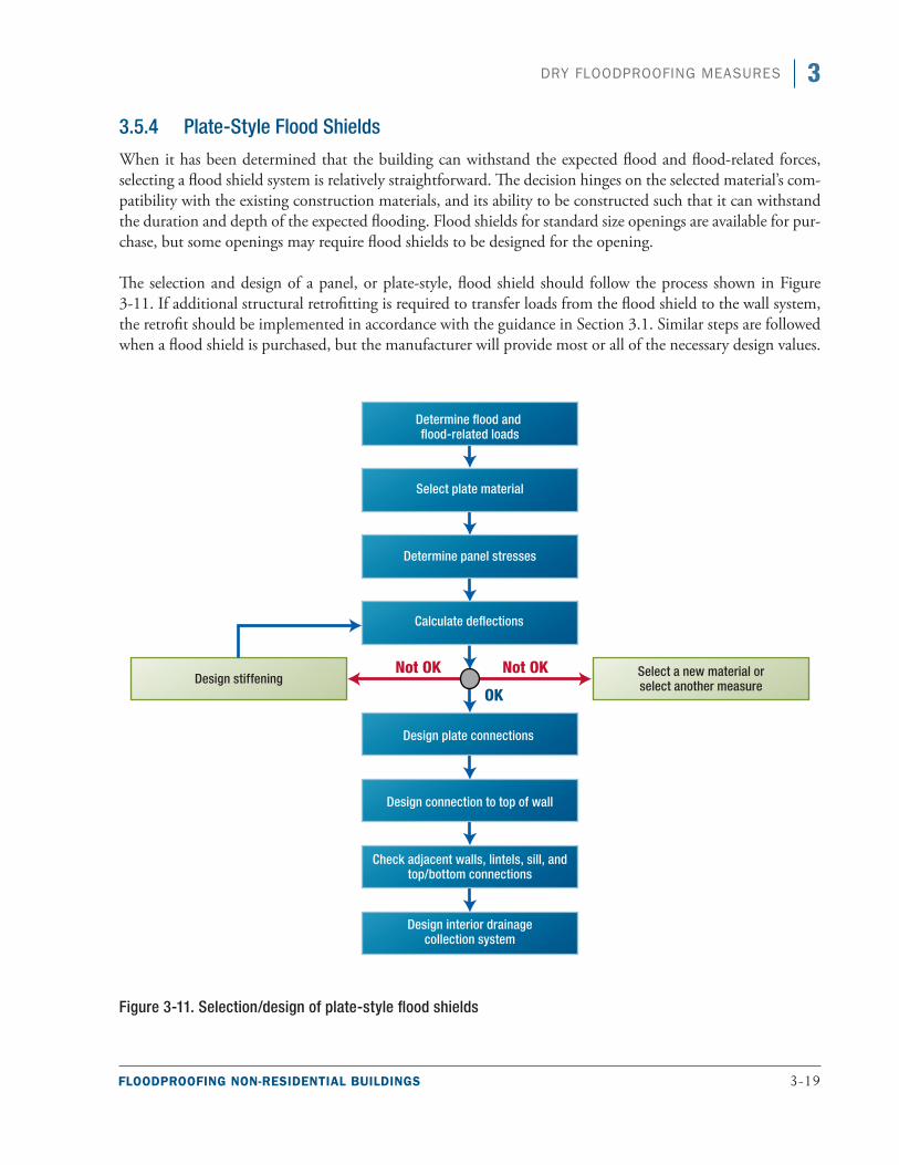
FLOODPROOFING NON-RESIDENTIAL BUILDINGS 3-19
3DRY FLOODPROOFING MEASURES
3.5.4 Plate-Style Flood Shields
When it has been determined that the building can withstand the expected flood and flood-related forces, selecting a flood shield system is relatively straightforward. The decision hinges on the selected material’s com-patibility with the existing construction materials, and its ability to be constructed such that it can withstand the duration and depth of the expected flooding. Flood shields for standard size openings are available for pur-chase, but some openings may require flood shields to be designed for the opening.
The selection and design of a panel, or plate-style, flood shield should follow the process shown in Figure 3-11. If additional structural retrofitting is required to transfer loads from the flood shield to the wall system, the retrofit should be implemented in accordance with the guidance in Section 3.1. Similar steps are followed when a flood shield is purchased, but the manufacturer will provide most or all of the necessary design values.
Figure 3-11. Selection/design of plate-style flood shields
3-20 FLOODPROOFING NON-RESIDENTIAL BUILDINGS
3 DRY FLOODPROOFING MEASURES
The process for selecting and designing plate-style flood shields is as follows:
Step 1. Determine the flood and flood-related loads. Loads calculated in Chapter 2 should be used to determine the flood loads acting on the shield. The height of the flood protection level (the depth as it relates to the panel) and the related flood loads calculated per linear foot should be applied over the entire width of the area to be protected by the shield.
Step 2. Select the plate shield material. Material selection is driven by the size of the opening and duration of flooding. Factors to consider are:
a. Flood duration: Select steel or aluminum materials for long-duration flooding and consider marine grade plywood materials for short-duration, shallow flooding.
b. Size of opening: Select steel and aluminum materials with stiffeners for larger openings and shored marine grade plywood with appropriate bracing for small openings.
c. Installation: Should be quick and require minimal effort to minimize personnel needs.
Step 3. Determine panel stresses. The designer should check the flood shield panel either as a plate or a horizontal/vertical span across the opening, as follows:
a. Using end conditions and attachments to determine how the panel will work, calculate stresses based on bending of the plate. In larger shield applications, also compute the end shear. b. Compare these stresses to the allowable stresses from a material design value source.
c. Address shields that have a free end at the top or other unusual configuration on a case-by-case basis.
d. Adjust the plate thickness to select the most economical section. If the shield does not work for larger thicknesses, add stiffeners.
e. Refer to the American Institute of Steel Construction (AISC) 325, Steel Construction Manual, for steel plate design (AISC 2011); the Aluminum Association’s (AA’s) Aluminum Design Manual for aluminum design (AA 2010); the ANSI/AF&PA National Design Specification for Wood Construction for plywood design (ANSI/AF&PA 2005); and applicable codes and standards.
Step 4A. Check deflections. A shield that is acceptable for stresses may not be acceptable for deflection. Deflection may be controlled by using alternative plate materials. Check deflections as follows:
a. Calculate deflections for the shield and evaluate on the basis of connections and sealants.
b. If the stresses are such that the loads will permanently deflect the shield or cause leakage around the gasket material, the deflection should be considered unacceptable and stiffeners should be added.
c. Refer to the AISC 325 for steel plate design (AISC 2011), the Aluminum Design Manual (AA 2010) for aluminum design, the ANSI/AF&PA National Design Specification for Wood Construction for plywood design (ANSI/AF&PA 2005), and applicable codes and standards.
FLOODPROOFING NON-RESIDENTIAL BUILDINGS 3-21
3DRY FLOODPROOFING MEASURES
Step 4B. Design stiffeners as required. Plate overstress or deflection may be solved by using stiffeners. Design the stiffening as follows:
a. Select the section to be used as a stiffener. Angles may be used for steel or aluminum shields and wood stock for plywood shields.
b. Calculate the stresses and deflection based on the composite section of stiffener and plate.
c. Calculate the horizontal shear between the sections, and design the connections to carry this load.
d. Keep plate connections and frame in mind when detailing stiffeners.
e. Refer to the AISC 325 for steel plate design (AISC 2011), the Aluminum Design Manual, (AA 2010) for aluminum design, the ANSI/AF&PA National Design Specification for Wood Construction for plywood design (ANSI/AF&PA 2005), and applicable codes and standards.
Step 5A. Design the connections and hardware. Plate connections must be easy to install and able to handle the loads from the plate into the frame and surrounding wall.
a. Determine the type of connection (e.g., hinged, free top, bolted, latching dogs).
b. Consider ease of installation and aesthetics. Any hardware that can be permanently attached to walls systems or the shields will eliminate the potential to lose hardware.
c. Design the connection to operate in conjunction with gasket or sealant to prevent leakage.
d. Design the connection to be capable of resisting live loads in the direction opposite of surges.
e. Refer to the AISC 325 for steel plate design (AISC 2011), the Aluminum Design Manual (AA 2010) for aluminum design, the ANSI/AF&PA National Design Specification for Wood Construction for plywood design (ANSI/AF&PA 2005), and applicable codes and standards.
Step 5B. Select the gasket or waterproofing. Gaskets or waterproofing materials, which form the interface between shields and the existing structure, are vital elements of the dry floodproofing system. They should be flexible, durable, and applicable to the specific situation.
a. Determine the type of gasket or waterproofing required. Gasket/waterproofing must be able to withstand expected forces and able to function during climatic extremes.
b. Consider ease of installation and ability to work with plate/connections as a single unit.
c. Refer to the manufacturer’s literature and check against duration/depth of flooding, the appli-cability to selected building materials, and storage requirements. Some gasket materials can be damaged by extended exposure to sunlight or other weather conditions. Vulnerability to sun-light or weather may affect the selection of the gasket or waterproofing material.
Step 6. Check adjacent walls, lintels, sills, and top/bottom connections. Resistance of structural com-ponents adjacent to the shield such as walls, lintels, sills, and top/bottom connections should be checked against maximum loading conditions. Different methods of attachment may load the
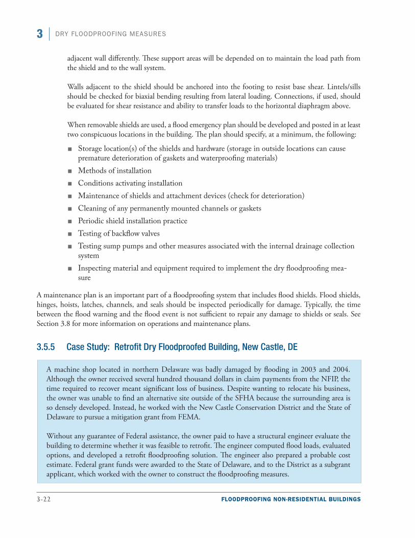
3-22 FLOODPROOFING NON-RESIDENTIAL BUILDINGS
3 DRY FLOODPROOFING MEASURES
adjacent wall differently. These support areas will be depended on to maintain the load path from the shield and to the wall system.
Walls adjacent to the shield should be anchored into the footing to resist base shear. Lintels/sills should be checked for biaxial bending resulting from lateral loading. Connections, if used, should be evaluated for shear resistance and ability to transfer loads to the horizontal diaphragm above.
When removable shields are used, a flood emergency plan should be developed and posted in at least two conspicuous locations in the building. The plan should specify, at a minimum, the following:
■■ Storage location(s) of the shields and hardware (storage in outside locations can cause premature deterioration of gaskets and waterproofing materials)
■■ Methods of installation■■ Conditions activating installation■■ Maintenance of shields and attachment devices (check for deterioration)■■ Cleaning of any permanently mounted channels or gaskets■■ Periodic shield installation practice ■■ Testing of backflow valves■■ Testing sump pumps and other measures associated with the internal drainage collection
system■■ Inspecting material and equipment required to implement the dry floodproofing mea-
sure
A maintenance plan is an important part of a floodproofing system that includes flood shields. Flood shields, hinges, hoists, latches, channels, and seals should be inspected periodically for damage. Typically, the time between the flood warning and the flood event is not sufficient to repair any damage to shields or seals. See Section 3.8 for more information on operations and maintenance plans.
3.5.5 Case Study: Retrofit Dry Floodproofed Building, New Castle, DE
A machine shop located in northern Delaware was badly damaged by flooding in 2003 and 2004. Although the owner received several hundred thousand dollars in claim payments from the NFIP, the time required to recover meant significant loss of business. Despite wanting to relocate his business, the owner was unable to find an alternative site outside of the SFHA because the surrounding area is so densely developed. Instead, he worked with the New Castle Conservation District and the State of Delaware to pursue a mitigation grant from FEMA.
Without any guarantee of Federal assistance, the owner paid to have a structural engineer evaluate the building to determine whether it was feasible to retrofit. The engineer computed flood loads, evaluated options, and developed a retrofit floodproofing solution. The engineer also prepared a probable cost estimate. Federal grant funds were awarded to the State of Delaware, and to the District as a subgrant applicant, which worked with the owner to construct the floodproofing measures.
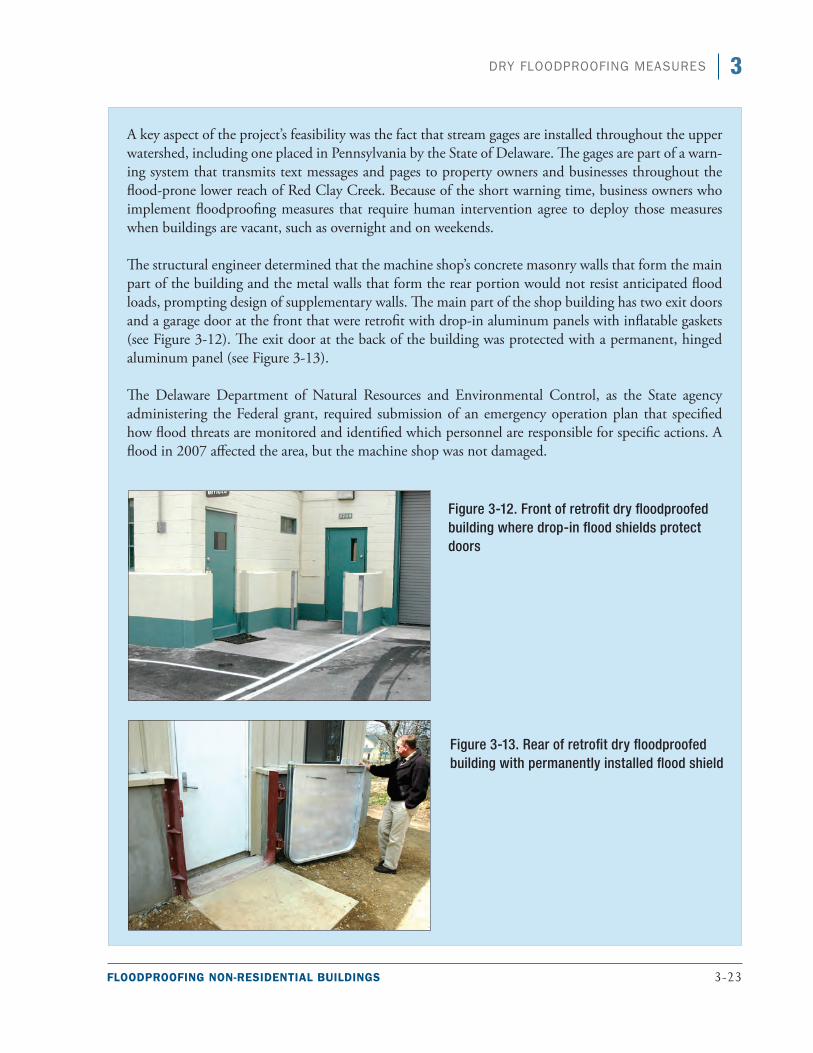
FLOODPROOFING NON-RESIDENTIAL BUILDINGS 3-23
3DRY FLOODPROOFING MEASURES
A key aspect of the project’s feasibility was the fact that stream gages are installed throughout the upper watershed, including one placed in Pennsylvania by the State of Delaware. The gages are part of a warn-ing system that transmits text messages and pages to property owners and businesses throughout the flood-prone lower reach of Red Clay Creek. Because of the short warning time, business owners who implement floodproofing measures that require human intervention agree to deploy those measures when buildings are vacant, such as overnight and on weekends.
The structural engineer determined that the machine shop’s concrete masonry walls that form the main part of the building and the metal walls that form the rear portion would not resist anticipated flood loads, prompting design of supplementary walls. The main part of the shop building has two exit doors and a garage door at the front that were retrofit with drop-in aluminum panels with inflatable gaskets (see Figure 3-12). The exit door at the back of the building was protected with a permanent, hinged aluminum panel (see Figure 3-13).
The Delaware Department of Natural Resources and Environmental Control, as the State agency administering the Federal grant, required submission of an emergency operation plan that specified how flood threats are monitored and identified which personnel are responsible for specific actions. A flood in 2007 affected the area, but the machine shop was not damaged.
Figure 3-12. Front of retrofit dry floodproofed building where drop-in flood shields protect doors
Figure 3-13. Rear of retrofit dry floodproofed building with permanently installed flood shield
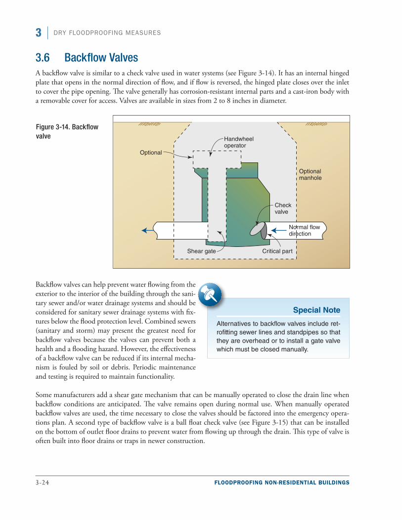
3-24 FLOODPROOFING NON-RESIDENTIAL BUILDINGS
3 DRY FLOODPROOFING MEASURES
3.6 Backflow ValvesA backflow valve is similar to a check valve used in water systems (see Figure 3-14). It has an internal hinged plate that opens in the normal direction of flow, and if flow is reversed, the hinged plate closes over the inlet to cover the pipe opening. The valve generally has corrosion-resistant internal parts and a cast-iron body with a removable cover for access. Valves are available in sizes from 2 to 8 inches in diameter.
Backflow valves can help prevent water flowing from the exterior to the interior of the building through the sani-tary sewer and/or water drainage systems and should be considered for sanitary sewer drainage systems with fix-tures below the flood protection level. Combined sewers (sanitary and storm) may present the greatest need for backflow valves because the valves can prevent both a health and a flooding hazard. However, the effectiveness of a backflow valve can be reduced if its internal mecha-nism is fouled by soil or debris. Periodic maintenance and testing is required to maintain functionality.
Some manufacturers add a shear gate mechanism that can be manually operated to close the drain line when backflow conditions are anticipated. The valve remains open during normal use. When manually operated backflow valves are used, the time necessary to close the valves should be factored into the emergency opera-tions plan. A second type of backflow valve is a ball float check valve (see Figure 3-15) that can be installed on the bottom of outlet floor drains to prevent water from flowing up through the drain. This type of valve is often built into floor drains or traps in newer construction.
Figure 3-14. Backflow valve
Special Note
Alternatives to backflow valves include ret-rofitting sewer lines and standpipes so that they are overhead or to install a gate valve which must be closed manually.
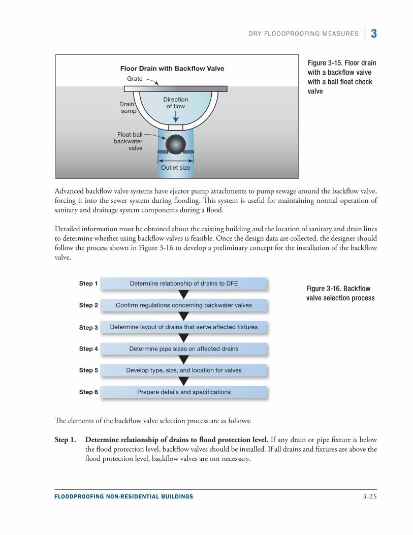
FLOODPROOFING NON-RESIDENTIAL BUILDINGS 3-25
3DRY FLOODPROOFING MEASURES
Advanced backflow valve systems have ejector pump attachments to pump sewage around the backflow valve, forcing it into the sewer system during flooding. This system is useful for maintaining normal operation of sanitary and drainage system components during a flood.
Detailed information must be obtained about the existing building and the location of sanitary and drain lines to determine whether using backflow valves is feasible. Once the design data are collected, the designer should follow the process shown in Figure 3-16 to develop a preliminary concept for the installation of the backflow valve.
The elements of the backflow valve selection process are as follows:
Step 1. Determine relationship of drains to flood protection level. If any drain or pipe fixture is below the flood protection level, backflow valves should be installed. If all drains and fixtures are above the flood protection level, backflow valves are not necessary.
Figure 3-15. Floor drain with a backflow valve with a ball float check valve
Figure 3-16. Backflow valve selection process
3-26 FLOODPROOFING NON-RESIDENTIAL BUILDINGS
3 DRY FLOODPROOFING MEASURES
Step 2. Confirm regulations on backflow valves. Based on information collected during the field inves-tigation, confirm the local code or governing regulations allow the use and installation of backflow valves.
Step 3. Determine the layout of drains that serve the affected fixtures. Sketch the floor plan of the build-ing showing the location of all plumbing fixtures, appliances, floor drains, and drain piping below the flood protection level.
Step 4. Determine pipe sizes on affected drains. Obtain the size of drainage lines below the flood protec-tion level from the field investigation or construction drawings.
Step 5. Determine type, size, and location for valves. Determine type, size, and location of backflow valves required, paying attention to any special conditions related to installation. Factors to be con-sidered are:
■■ Clearance for access and maintenance■■ Cutting and patching of concrete floors■■ Indicating on the floor plan sketch the tentative location(s) of the backflow valve(s) to
verify they do not conflict with other utility lines or equipment
At this point, the designer should confirm the preliminary design with the owner, discussing the fol-lowing items:
■■ Verify that proposed locations of backflow valves are feasible■■ Verify existing conditions at location of proposed backflow valves■■ Confirm the size and location of needed backflow valves■■ Confirm special considerations regarding existing conditions affecting design and installa-
tion of backflow valves
Step 6. Prepare details and specifications. The final plans and specifications should include the following items:
■■ Floor plan or site plan with location of backflow valves■■ Details, notes, and schedules:
■■ Backflow valve detail■■ Wall, floor, and wall penetration details■■ Installation notes■■ Equipment notes (or schedule)
■■ Specifications governing the installation of: ■■ Pipes and fittings■■ Insulation■■ Hangers and supports■■ Valves
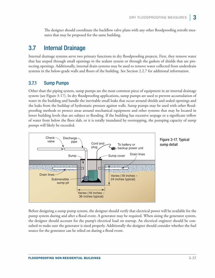
FLOODPROOFING NON-RESIDENTIAL BUILDINGS 3-27
3DRY FLOODPROOFING MEASURES
The designer should coordinate the backflow valve plans with any other floodproofing retrofit mea-sures that may be proposed for the same building.
3.7 Internal Drainage Internal drainage systems serve two primary functions in dry floodproofing projects. First, they remove water that has seeped through small openings in the sealant system or through the gaskets of shields that are pro-tecting openings. Additionally, internal drain systems may be used to remove water collected from underdrain systems in the below-grade walls and floors of the building. See Section 2.2.7 for additional information.
3.7.1 Sump Pumps
Other than the piping system, sump pumps are the most common piece of equipment in an internal drainage system (see Figure 3-17). In dry floodproofing applications, sump pumps are used to prevent accumulation of water in the building and handle the inevitable small leaks that occur around shields and sealed openings and the leaks from the buildup of hydrostatic pressure against walls. Sump pumps may be used with other flood-proofing methods to protect areas around mechanical equipment and other systems that may be located in lower building levels that are subject to flooding. If the building has excessive seepage or a significant inflow of water from below the floor slab, or it is totally inundated by overtopping, the pumping capacity of sump pumps will likely be exceeded.
Before designing a sump pump system, the designer should verify that electrical power will be available for the pump system during and after a flood event. A generator may be required. When sizing the generator system, the designer should account for the pump’s electrical load on startup. An electrical engineer should be con-sulted to make sure the generator is sized properly. Additionally the designer should consider whether the fuel source for the generator can be relied on during a flood event.
Figure 3-17. Typical sump detail
3-28 FLOODPROOFING NON-RESIDENTIAL BUILDINGS
3 DRY FLOODPROOFING MEASURES
Sump pump and pit systems are constructed so that the bottom of the pit is below the base of the floor slab. Water in the areas adjacent to the walls and floor migrate toward the pit along the lines of least water flow resis-tance. If the pit is located properly, water will flow toward and into the sump pit.
To remove water that has seeped into the dry floodproofed area, the floor slab should be sloped toward the sump pit(s). The slope will reduce the potential for water to accumulate before it reaches the sump pit. Placement of any equipment, storage items, or other potential obstructions should be considered so drainage is not impeded.
A path of reduced resistance may need to be constructed for water that has collected in the backfill material next to and adjacent to the building so that it can travel to the sump pit. Short pipe segments are inserted into holes drilled through the foundation walls into the backfill adjacent to the foundation wall. These pipe seg-ments are connected to larger diameter pipes running along a gravel-filled trench or cove area in the basement floor that leads to one or more sumps. Although a sump system is effective in areas with low water tables, it may be overwhelmed by high water tables.
Two commonly used types of sump pumps are the submersible and pedestal. The submersible type has a water-tight motor connected directly to the pump casing and is installed at the bottom of the sump. Pedestal sump pumps have an open motor supported on a pipe column with the pump at its base and a long shaft inside the column connecting the motor to the pump impeller.
Submersible pumps are preferred for smaller applications because they continue to operate if the water level exceeds the height of the pump. In larger or commercial applications, a pedestal floor-mounted pump is pre-ferred. Larger pumps require greater maintenance because of the larger volume of water they are designed to move. Larger pumps must therefore be mounted above the water collection pit for accessibility.
When selecting a sump pump for floodproofing applications, the designer should consider the advantages of each pump type and select a pump based on the requirements of the building. Considerations are as follows:
■■ Pump capacity (gallons per minute or gallons per hour)
■■ Pump head (vertical height the water is lifted)
■■ Frictional resistance of fluid flow in the discharge piping system
■■ Electrical power required (small non-residential buildings are usually powered by 120/240 volt, single-phase AC, but larger buildings may have three-phase systems with higher voltages)
■■ Type of pump activation switch system
The pump activation switch is an important component of the sump pump system. Many pumps use one of four types of switches: diaphragm, vertical action float, tethered float, or electronic free float. Although all of these switches are viable, the strengths and reliability of each one must be understood. Table 3-3 provides a comparison of the pump activation switch types.
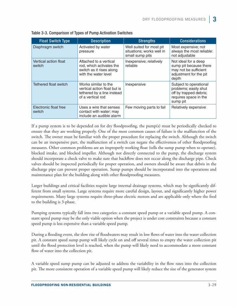
FLOODPROOFING NON-RESIDENTIAL BUILDINGS 3-29
3DRY FLOODPROOFING MEASURES
Table 3-3. Comparison of Types of Pump Activation Switches
Float Switch Type Description Strengths ConsiderationsDiaphragm switch Activated by water
pressureWell suited for most pit situations; works well in small sump pits
Most expensive; not always the most reliable: not adjustable
Vertical action float switch
Attached to a vertical rod, which activates the switch as it rises along with the water level
Inexpensive; relatively reliable
Not ideal for a deep sump pit because there may not be sufficient adjustment for the pit depth
Tethered float switch Works similar to the vertical action float but is tethered by a line instead of a vertical rod
Inexpensive Subject to operational problems; easily shut off by trapped debris; requires space in the sump pit
Electronic float free switch
Uses a wire that senses contact with water; may include an audible alarm
Few moving parts to fail Relatively expensive
If a pump system is to be depended on for dry floodproofing, the pump(s) must be periodically checked to ensure that they are working properly. One of the most common causes of failure is the malfunction of the switch. The owner must be familiar with the proper procedure for replacing the switch. Although the switch can be an inexpensive part, the malfunction of a switch can negate the effectiveness of other floodproofing measures. Other common problems are an improperly working float (tells the sump pump when to operate), blocked intake, and blocked impeller. Although not directly connected to the pump, the discharge system should incorporate a check valve to make sure that backflow does not occur along the discharge pipe. Check valves should be inspected periodically for proper operation, and owners should be aware that debris in the discharge pipe can prevent proper operation. Sump pumps should be incorporated into the operations and maintenance plan for the building along with other floodproofing measures.
Larger buildings and critical facilities require large internal drainage systems, which may be significantly dif-ferent from small systems. Large systems require more careful design, layout, and significantly higher power requirements. Many large systems require three-phase electric motors and are applicable only where the feed to the building is 3-phase.
Pumping systems typically fall into two categories: a constant speed pump or a variable speed pump. A con-stant speed pump may be the only viable option when the project is under cost constraints because a constant speed pump is less expensive than a variable speed pump.
During a flooding event, the slow rise of floodwaters may result in low flows of water into the water collection pit. A constant speed sump pump will likely cycle on and off several times to empty the water collection pit until the flood protection level is reached, when the pump will likely need to accommodate a more constant flow of water into the collection pit.
A variable speed sump pump can be adjusted to address the variability in the flow rates into the collection pit. The more consistent operation of a variable speed pump will likely reduce the size of the generator system
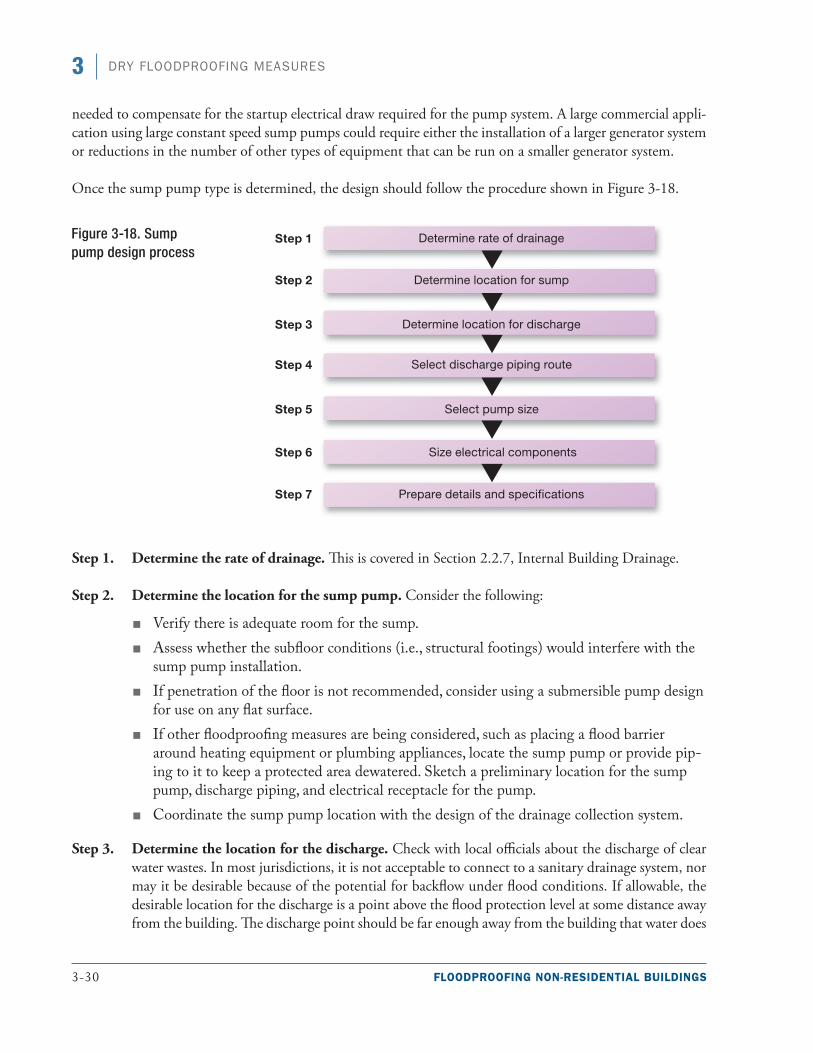
3-30 FLOODPROOFING NON-RESIDENTIAL BUILDINGS
3 DRY FLOODPROOFING MEASURES
needed to compensate for the startup electrical draw required for the pump system. A large commercial appli-cation using large constant speed sump pumps could require either the installation of a larger generator system or reductions in the number of other types of equipment that can be run on a smaller generator system.
Once the sump pump type is determined, the design should follow the procedure shown in Figure 3-18.
Step 1. Determine the rate of drainage. This is covered in Section 2.2.7, Internal Building Drainage.
Step 2. Determine the location for the sump pump. Consider the following:
■■ Verify there is adequate room for the sump.■■ Assess whether the subfloor conditions (i.e., structural footings) would interfere with the
sump pump installation.■■ If penetration of the floor is not recommended, consider using a submersible pump design
for use on any flat surface.■■ If other floodproofing measures are being considered, such as placing a flood barrier
around heating equipment or plumbing appliances, locate the sump pump or provide pip-ing to it to keep a protected area dewatered. Sketch a preliminary location for the sump pump, discharge piping, and electrical receptacle for the pump.
■■ Coordinate the sump pump location with the design of the drainage collection system.
Step 3. Determine the location for the discharge. Check with local officials about the discharge of clear water wastes. In most jurisdictions, it is not acceptable to connect to a sanitary drainage system, nor may it be desirable because of the potential for backflow under flood conditions. If allowable, the desirable location for the discharge is a point above the flood protection level at some distance away from the building. The discharge point should be far enough away from the building that water does
Figure 3-18. Sump pump design process
FLOODPROOFING NON-RESIDENTIAL BUILDINGS 3-31
3DRY FLOODPROOFING MEASURES
not infiltrate back into the building. From the information obtained during the field investigation, tentatively lay out the route of the discharge piping and locate the point of discharge.
Step 4. Select the discharge piping route.
■■ Minimize the length of pipe between sump and discharge point■■ Avoid utility and structural interferences along the route■■ Attach the discharge pipe to the structure as required by code■■ Protect the discharge point against erosion and install a downspout discharge block under
the sump pump pipe discharge
Step 5. Select the pump size. Sump pumps for non-residential use generally have motors from 1/6 to 3/4 horsepower and pumping capacities from 8 to 60 gpm. In selecting a pump, the designer needs to estimate the rate of flow of floodwater that will infiltrate into the space (gpm or gallons per hour [gph]). Additionally, the total dynamic head for the sump discharge must be determined. The total dynamic head equals the vertical distance from the pump to the point of discharge plus the frictional resistance to flow through the piping, the fittings, and the transitions. The head loss from pipe fric-tion can be obtained from hydraulic engineering data books and depends on the pipe material and pipe length.
Other pump size considerations may be:
■■ Physical size of the sump pump given the area available to place the pump■■ Recommendations of the sump pump manufacturer regarding pump cycling or other
constraints
The designer should take these considerations into account in locating the sump and configuring the sump pump discharge.
Step 6. Size the electrical components.
■■ Obtain horsepower and full load amperage rating■■ Select a ground fault interrupter circuit, as required by code■■ Size minimum circuit ampacity and maximum fuse size■■ Size maximum circuit breaker size■■ Obtain recommended fuse size or circuit breaker size from manufacturer and compare to
above maximum and minimum National Electrical Code sizes
At this point, the designer should prepare a floor plan sketch showing the location of the sump pump, routing of the discharge line, location of the discharge point, and the preliminary specifica-tions for the sump pump, sump pit, piping, and appurtenances and confirm the preliminary design with the owner or facility management, covering the following items:
■■ Verify that the proposed location of the sump pump and pit is feasible■■ Verify electrical availability for the sump pump
3-32 FLOODPROOFING NON-RESIDENTIAL BUILDINGS
3 DRY FLOODPROOFING MEASURES
■■ Verify existing conditions along the proposed routing of discharge piping and at the dis-charge pipe termination
■■ Confirm selection and size of the sump pump■■ Confirm size and location of the sump pit■■ Confirm special considerations regarding existing conditions affecting design and installa-
tion of the sump pump and sump pit
Step 7. Prepare details and specifications.
Prepare final plans showing:
■■ Floor plan with locations of sump and backflow valves■■ Routing of discharge pipe and location of discharge point■■ Sump pump detail■■ Wall, floor, and wall penetration details:
■■ Sump construction details
■■ Installation notes
■■ Equipment notes (or schedule)
■■ Specifications (on drawing or as a specifications booklet):■■ Pipe and fittings
■■ Insulation
■■ Hangers and supports
■■ Valves (including backwater valves)
■■ Sump pumps
■■ Coordinate plans with the work of others on additional floodproofing measures that may be proposed at the same building
3.7.2 Pressure Relief Systems
If flooding exceeds the level of protection and water fills the building, pumping out an area before the floodwa-ter has receded can cause the walls to collapse if hydrostatic pressure from the floodwater exceeds the structural resistance of the foundation walls and the floor slab. Incorporating a pressure relief system is recommended to avoid structural damage to the building.
Pressure relief systems are similar to wet floodproofing measures in that they allow floodwaters into an area rather than risking damage by hydrostatic pressures. The systems allow for some level of dry floodproofing and then release the hydrostatic pressure if water levels exceed a specific height. A pressure relief system provides an added degree of protection against structural failure of a new building or for an existing structure that cannot be modified to reduce uplift pressures.
FLOODPROOFING NON-RESIDENTIAL BUILDINGS 3-33
3DRY FLOODPROOFING MEASURES
Installing some type of pressure relief system is generally desirable. For floor systems that are not thick enough or sufficiently reinforced to resist buoyancy forces, the system may be a series of relief valves equally spaced across the floor slab. If floodwaters begin to collect in the soil under the slab, the relief valves will allow the water to percolate through the floor slab, eliminating the buoyancy forces. Dry floodproofing protection will not be achieved, but this is preferable to losing the structure.
3.8 Flood Emergency Operations Plan and Inspection and Maintenance Plan
All dry floodproofed buildings must maintain a Flood Emergency Operations Plan and an Inspection and Maintenance Plan. The complexity of these plans depends largely on whether the dry floodproofing measures are passive or active and how much human intervention the active measures require. If ASCE 24 is required to be followed for the retrofit design, these plans will need to be approved by the Authority Having Jurisdiction. Both the Flood Emergency Operations Plan and the Inspection and Maintenance Plan should be drafted and submitted as part of the building permit application. More information on the minimum requirements for operations, maintenance, and inspection plans is available in Sections 2.5.4 and 2.5.5. The following para-graphs describe in more detail the typical components of a dry floodproofing measure that would be inspected and what common failures an inspector might see.
When performing routine inspections of dry floodproofing measures, gaskets and attachment hardware should be evaluated to determine whether they are still in good condition. Missing or deteriorated gaskets (see Figure 3.19) should be replaced with materials that are designed for use with the dry floodproofing shields. Shields and anchorage hardware should be installed at least annually to verify that all necessary hardware is available. A recommended practice is for owners to test their dry floodproofing components when renewing their flood policy each year. Emergency power sources and sump pumps should also be tested to verify that they are also in good working order. Sump pumps should be tested using the emergency power source rather than using the normal power source. Some dry floodproofing measures incorporate the use of leak detectors, which should also be tested. An inspection of the exterior of the building is also necessary to verify that no additional penetra-tions have been made below the DFE to which the dry floodproofing measure protects. Plumbing, electrical, mechanical, communications, or other penetrations can be installed over time and render the dry floodproof-ing ineffective if not properly sealed. Although sealing these penetrations is the building owner’s responsibility, the design professional should make it clear to the building owner that failure to maintain the dry floodproof-ing measures can result in either greater water intrusion than the sump pump system was designed for or, in a worst case scenario, water infiltration to a degree that renders the dry floodproofing measures useless.
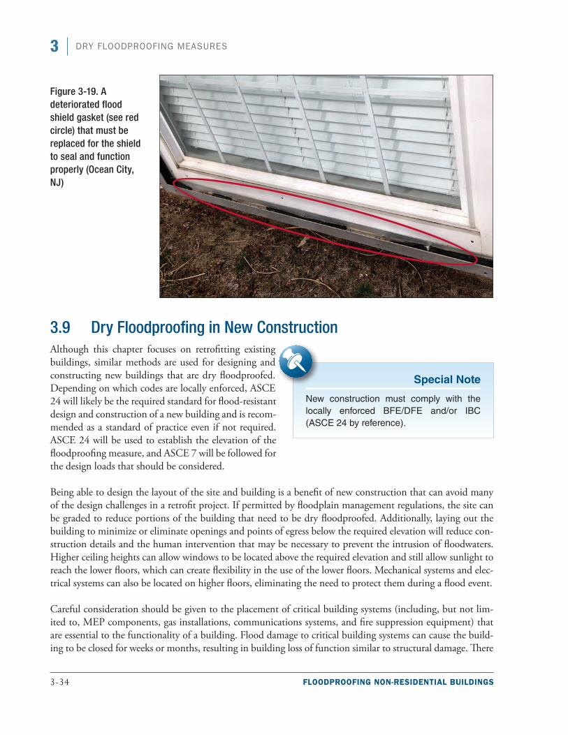
3-34 FLOODPROOFING NON-RESIDENTIAL BUILDINGS
3 DRY FLOODPROOFING MEASURES
3.9 Dry Floodproofing in New ConstructionAlthough this chapter focuses on retrofitting existing buildings, similar methods are used for designing and constructing new buildings that are dry floodproofed. Depending on which codes are locally enforced, ASCE 24 will likely be the required standard for flood-resistant design and construction of a new building and is recom-mended as a standard of practice even if not required. ASCE 24 will be used to establish the elevation of the floodproofing measure, and ASCE 7 will be followed for the design loads that should be considered.
Being able to design the layout of the site and building is a benefit of new construction that can avoid many of the design challenges in a retrofit project. If permitted by floodplain management regulations, the site can be graded to reduce portions of the building that need to be dry floodproofed. Additionally, laying out the building to minimize or eliminate openings and points of egress below the required elevation will reduce con-struction details and the human intervention that may be necessary to prevent the intrusion of floodwaters. Higher ceiling heights can allow windows to be located above the required elevation and still allow sunlight to reach the lower floors, which can create flexibility in the use of the lower floors. Mechanical systems and elec-trical systems can also be located on higher floors, eliminating the need to protect them during a flood event.
Careful consideration should be given to the placement of critical building systems (including, but not lim-ited to, MEP components, gas installations, communications systems, and fire suppression equipment) that are essential to the functionality of a building. Flood damage to critical building systems can cause the build-ing to be closed for weeks or months, resulting in building loss of function similar to structural damage. There
Special Note
New construction must comply with the locally enforced BFE/DFE and/or IBC (ASCE 24 by reference).
Figure 3-19. A deteriorated flood shield gasket (see red circle) that must be replaced for the shield to seal and function properly (Ocean City, NJ)
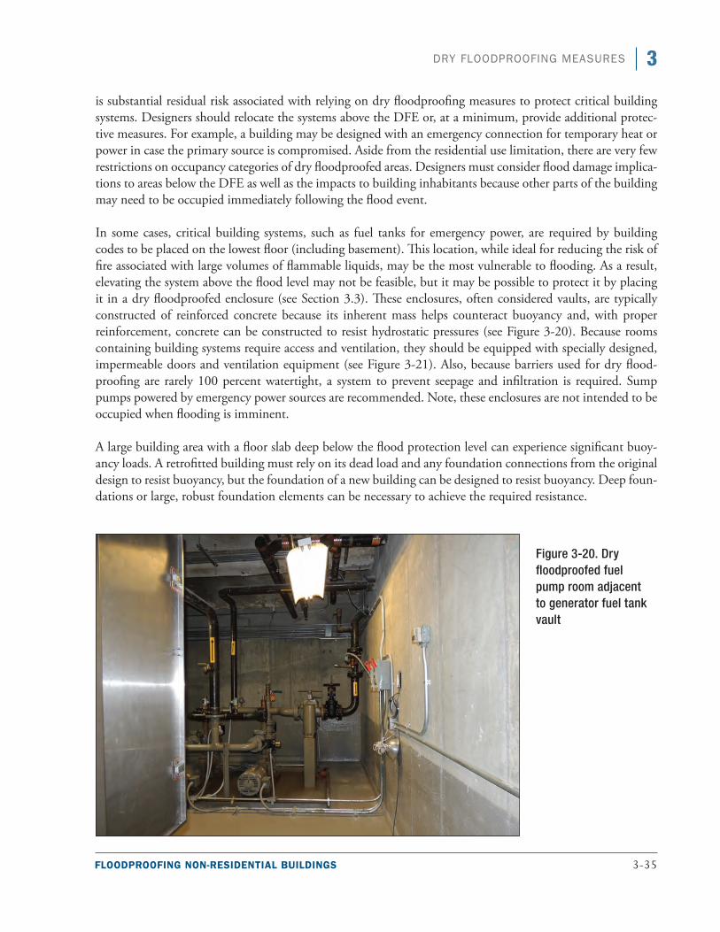
FLOODPROOFING NON-RESIDENTIAL BUILDINGS 3-35
3DRY FLOODPROOFING MEASURES
is substantial residual risk associated with relying on dry floodproofing measures to protect critical building systems. Designers should relocate the systems above the DFE or, at a minimum, provide additional protec-tive measures. For example, a building may be designed with an emergency connection for temporary heat or power in case the primary source is compromised. Aside from the residential use limitation, there are very few restrictions on occupancy categories of dry floodproofed areas. Designers must consider flood damage implica-tions to areas below the DFE as well as the impacts to building inhabitants because other parts of the building may need to be occupied immediately following the flood event.
In some cases, critical building systems, such as fuel tanks for emergency power, are required by building codes to be placed on the lowest floor (including basement). This location, while ideal for reducing the risk of fire associated with large volumes of flammable liquids, may be the most vulnerable to flooding. As a result, elevating the system above the flood level may not be feasible, but it may be possible to protect it by placing it in a dry floodproofed enclosure (see Section 3.3). These enclosures, often considered vaults, are typically constructed of reinforced concrete because its inherent mass helps counteract buoyancy and, with proper reinforcement, concrete can be constructed to resist hydrostatic pressures (see Figure 3-20). Because rooms containing building systems require access and ventilation, they should be equipped with specially designed, impermeable doors and ventilation equipment (see Figure 3-21). Also, because barriers used for dry flood-proofing are rarely 100 percent watertight, a system to prevent seepage and infiltration is required. Sump pumps powered by emergency power sources are recommended. Note, these enclosures are not intended to be occupied when flooding is imminent.
A large building area with a floor slab deep below the flood protection level can experience significant buoy-ancy loads. A retrofitted building must rely on its dead load and any foundation connections from the original design to resist buoyancy, but the foundation of a new building can be designed to resist buoyancy. Deep foun-dations or large, robust foundation elements can be necessary to achieve the required resistance.
Figure 3-20. Dry floodproofed fuel pump room adjacent to generator fuel tank vault
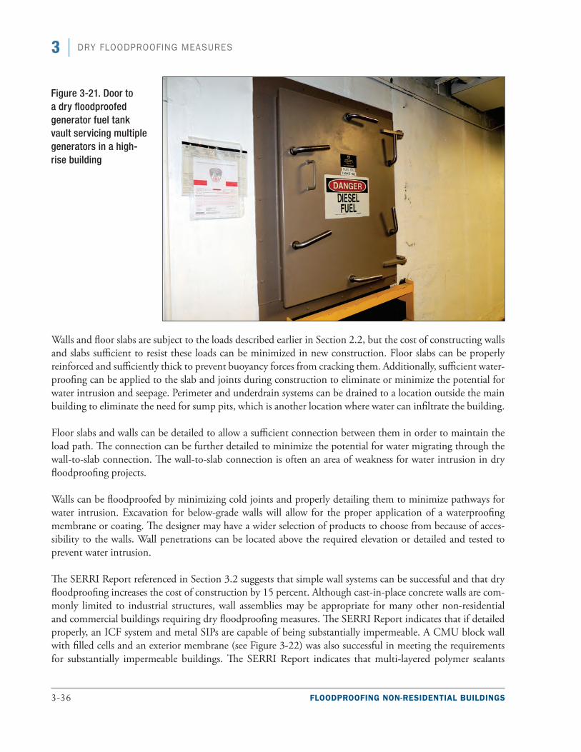
3-36 FLOODPROOFING NON-RESIDENTIAL BUILDINGS
3 DRY FLOODPROOFING MEASURES
Figure 3-21. Door to a dry floodproofed generator fuel tank vault servicing multiple generators in a high-rise building
Walls and floor slabs are subject to the loads described earlier in Section 2.2, but the cost of constructing walls and slabs sufficient to resist these loads can be minimized in new construction. Floor slabs can be properly reinforced and sufficiently thick to prevent buoyancy forces from cracking them. Additionally, sufficient water-proofing can be applied to the slab and joints during construction to eliminate or minimize the potential for water intrusion and seepage. Perimeter and underdrain systems can be drained to a location outside the main building to eliminate the need for sump pits, which is another location where water can infiltrate the building.
Floor slabs and walls can be detailed to allow a sufficient connection between them in order to maintain the load path. The connection can be further detailed to minimize the potential for water migrating through the wall-to-slab connection. The wall-to-slab connection is often an area of weakness for water intrusion in dry floodproofing projects.
Walls can be floodproofed by minimizing cold joints and properly detailing them to minimize pathways for water intrusion. Excavation for below-grade walls will allow for the proper application of a waterproofing membrane or coating. The designer may have a wider selection of products to choose from because of acces-sibility to the walls. Wall penetrations can be located above the required elevation or detailed and tested to prevent water intrusion.
The SERRI Report referenced in Section 3.2 suggests that simple wall systems can be successful and that dry floodproofing increases the cost of construction by 15 percent. Although cast-in-place concrete walls are com-monly limited to industrial structures, wall assemblies may be appropriate for many other non-residential and commercial buildings requiring dry floodproofing measures. The SERRI Report indicates that if detailed properly, an ICF system and metal SIPs are capable of being substantially impermeable. A CMU block wall with filled cells and an exterior membrane (see Figure 3-22) was also successful in meeting the requirements for substantially impermeable buildings. The SERRI Report indicates that multi-layered polymer sealants
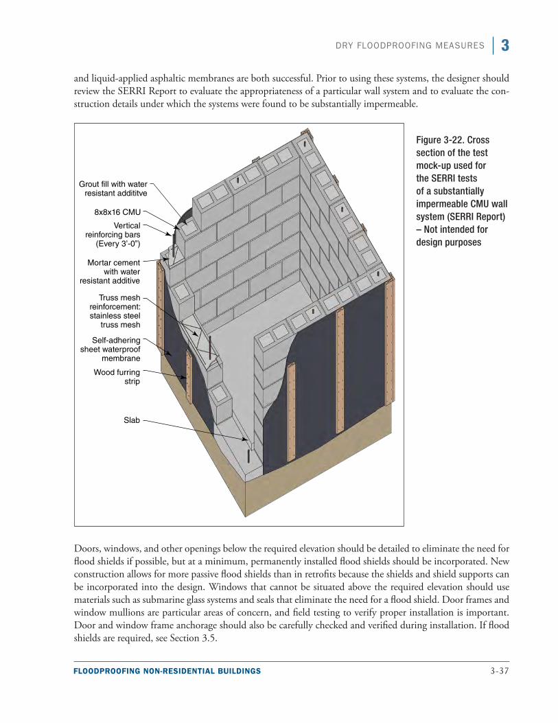
FLOODPROOFING NON-RESIDENTIAL BUILDINGS 3-37
3DRY FLOODPROOFING MEASURES
and liquid-applied asphaltic membranes are both successful. Prior to using these systems, the designer should review the SERRI Report to evaluate the appropriateness of a particular wall system and to evaluate the con-struction details under which the systems were found to be substantially impermeable.
Doors, windows, and other openings below the required elevation should be detailed to eliminate the need for flood shields if possible, but at a minimum, permanently installed flood shields should be incorporated. New construction allows for more passive flood shields than in retrofits because the shields and shield supports can be incorporated into the design. Windows that cannot be situated above the required elevation should use materials such as submarine glass systems and seals that eliminate the need for a flood shield. Door frames and window mullions are particular areas of concern, and field testing to verify proper installation is important. Door and window frame anchorage should also be carefully checked and verified during installation. If flood shields are required, see Section 3.5.
Figure 3-22. Cross section of the test mock-up used for the SERRI tests of a substantially impermeable CMU wall system (SERRI Report) – Not intended for design purposes
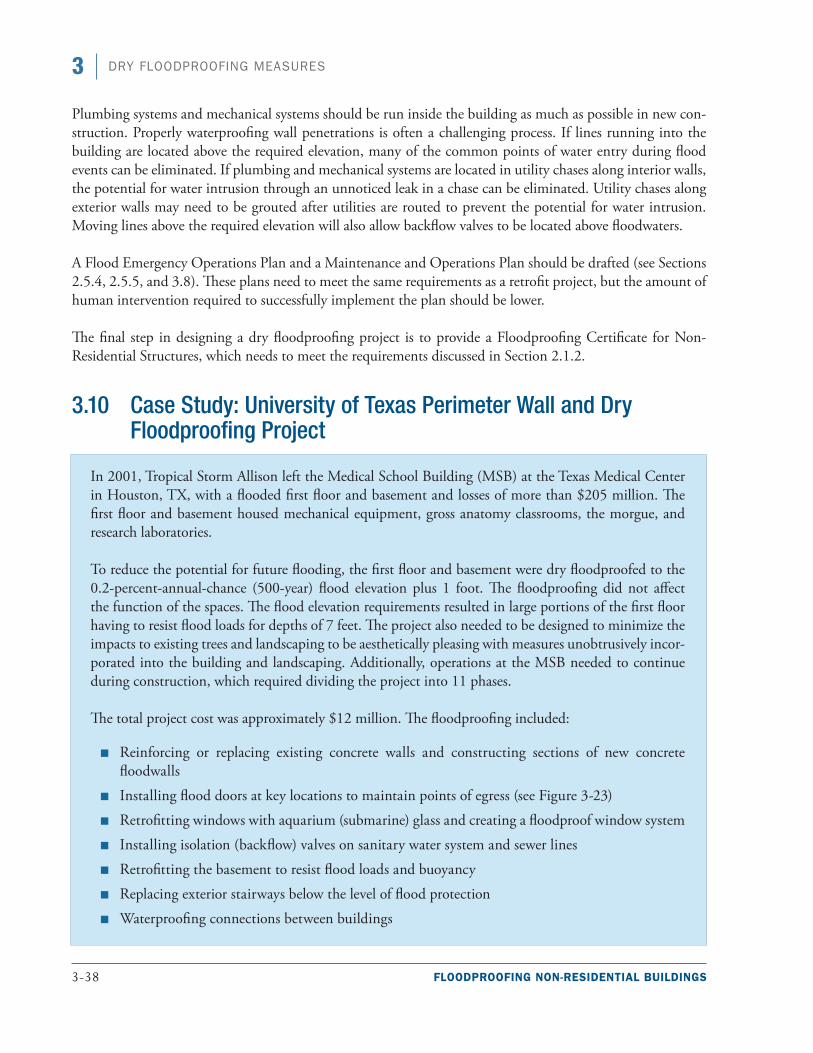
3-38 FLOODPROOFING NON-RESIDENTIAL BUILDINGS
3 DRY FLOODPROOFING MEASURES
Plumbing systems and mechanical systems should be run inside the building as much as possible in new con-struction. Properly waterproofing wall penetrations is often a challenging process. If lines running into the building are located above the required elevation, many of the common points of water entry during flood events can be eliminated. If plumbing and mechanical systems are located in utility chases along interior walls, the potential for water intrusion through an unnoticed leak in a chase can be eliminated. Utility chases along exterior walls may need to be grouted after utilities are routed to prevent the potential for water intrusion. Moving lines above the required elevation will also allow backflow valves to be located above floodwaters.
A Flood Emergency Operations Plan and a Maintenance and Operations Plan should be drafted (see Sections 2.5.4, 2.5.5, and 3.8). These plans need to meet the same requirements as a retrofit project, but the amount of human intervention required to successfully implement the plan should be lower.
The final step in designing a dry floodproofing project is to provide a Floodproofing Certificate for Non-Residential Structures, which needs to meet the requirements discussed in Section 2.1.2.
3.10 Case Study: University of Texas Perimeter Wall and Dry Floodproofing Project
In 2001, Tropical Storm Allison left the Medical School Building (MSB) at the Texas Medical Center in Houston, TX, with a flooded first floor and basement and losses of more than $205 million. The first floor and basement housed mechanical equipment, gross anatomy classrooms, the morgue, and research laboratories.
To reduce the potential for future flooding, the first floor and basement were dry floodproofed to the 0.2-percent-annual-chance (500-year) flood elevation plus 1 foot. The floodproofing did not affect the function of the spaces. The flood elevation requirements resulted in large portions of the first floor having to resist flood loads for depths of 7 feet. The project also needed to be designed to minimize the impacts to existing trees and landscaping to be aesthetically pleasing with measures unobtrusively incor-porated into the building and landscaping. Additionally, operations at the MSB needed to continue during construction, which required dividing the project into 11 phases.
The total project cost was approximately $12 million. The floodproofing included:
■■ Reinforcing or replacing existing concrete walls and constructing sections of new concrete floodwalls
■■ Installing flood doors at key locations to maintain points of egress (see Figure 3-23)
■■ Retrofitting windows with aquarium (submarine) glass and creating a floodproof window system
■■ Installing isolation (backflow) valves on sanitary water system and sewer lines
■■ Retrofitting the basement to resist flood loads and buoyancy
■■ Replacing exterior stairways below the level of flood protection
■■ Waterproofing connections between buildings

FLOODPROOFING NON-RESIDENTIAL BUILDINGS 3-39
3DRY FLOODPROOFING MEASURES
Because some sections of the original first floor walls were curtain walls, they could not be properly retrofitted to resist the flood loads. The curtain walls were replaced with reinforced concrete walls. One area of the main building required that the concrete walls be constructed offset from the building to maintain the continuity of the wall system.
Nine flood doors were added to maintain points of egress. Some of the flood doors have dual inflatable gaskets to provide redundant protection. The flood door seal pressures and closure bolts are monitored from a remote and secure location during a storm event and are on an independently powered build-ing automation system.
Retrofitting windows was a particular challenge because of the flood elevation requirements. Aquarium (submarine) glass was used to allow natural light to enter the first floor. The retrofit consisted of replac-ing the conventional window wall system with laminated glass panels and oversized mullions to resist flood loads.
Plumbing systems (sanitary water systems and sewer lines) were protected with isolation valves that act as backflow prevention devices. Loss of power tips the devices and prevents potential floodwaters from entering the building.
Ross Sterling Avenue, a public street that passes under the MSB, provides access to other areas of the medical center (see Figure 3-24). Local authorities would not allow floodgates to be placed across the road, so the road was raised to create a berm that provides protection to the level of the base flood. Because Ross Sterling Avenue passes under the second floor of the building, all penetrations through the walls were waterproofed, and the mechanical chases were grouted to seal the area between the chase and the ductwork and pipes inside the chase. The waterproofed areas allow Ross Sterling Avenue to flood without compromising the building.
In the portion of the basement that is under Ross Sterling Avenue, the existing pan joist system of the basemtent ceiling was strengthened with fiber-reinforced polymer materials to minimize space consumption relative to existing and future equipment. Because of the potential buoyancy forces acting on the basement slab, some areas were retrofitted with beams and tie-down plates, and some equipment required additional anchoring. All existing expansion joints and wall cracks were filled
Figure 3-23. Flood doors incorporated into the existing building façade (source: Walter P. Moore)
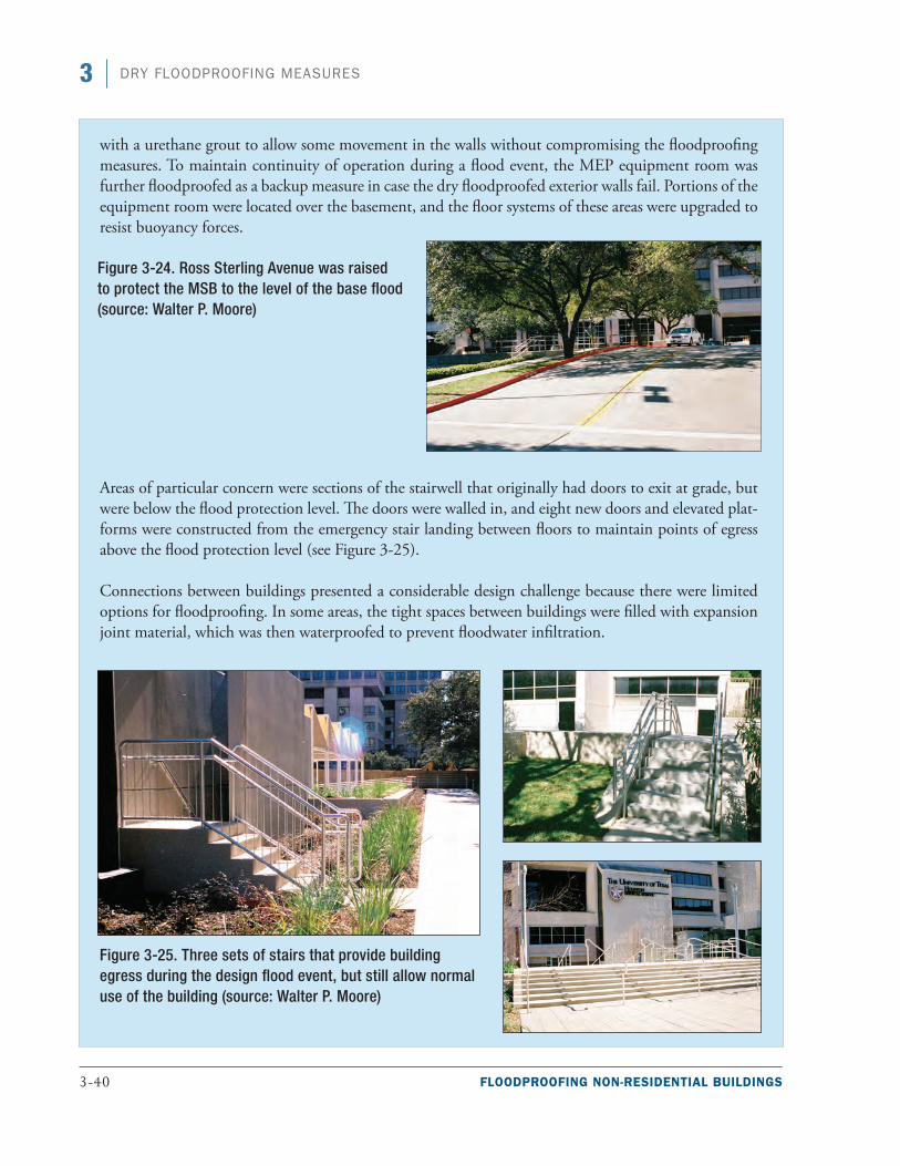
3-40 FLOODPROOFING NON-RESIDENTIAL BUILDINGS
3 DRY FLOODPROOFING MEASURES
with a urethane grout to allow some movement in the walls without compromising the floodproofing measures. To maintain continuity of operation during a flood event, the MEP equipment room was further floodproofed as a backup measure in case the dry floodproofed exterior walls fail. Portions of the equipment room were located over the basement, and the floor systems of these areas were upgraded to resist buoyancy forces.
Areas of particular concern were sections of the stairwell that originally had doors to exit at grade, but were below the flood protection level. The doors were walled in, and eight new doors and elevated plat-forms were constructed from the emergency stair landing between floors to maintain points of egress above the flood protection level (see Figure 3-25).
Connections between buildings presented a considerable design challenge because there were limited options for floodproofing. In some areas, the tight spaces between buildings were filled with expansion joint material, which was then waterproofed to prevent floodwater infiltration.
Figure 3-25. Three sets of stairs that provide building egress during the design flood event, but still allow normal use of the building (source: Walter P. Moore)
Figure 3-24. Ross Sterling Avenue was raised to protect the MSB to the level of the base flood (source: Walter P. Moore)
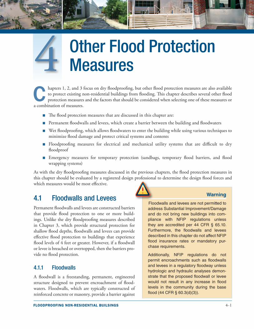
FLOODPROOFING NON-RESIDENTIAL BUILSINGS 4-1
Other Flood Protection Measures
C hapters 1, 2, and 3 focus on dry floodproofing, but other flood protection measures are also available to protect existing non-residential buildings from flooding. This chapter describes several other flood protection measures and the factors that should be considered when selecting one of these measures or
a combination of measures.
■■ The flood protection measures that are discussed in this chapter are:
■■ Permanent floodwalls and levees, which create a barrier between the building and floodwaters
■■ Wet floodproofing, which allows floodwaters to enter the building while using various techniques to minimize flood damage and protect critical systems and contents
■■ Floodproofing measures for electrical and mechanical utility systems that are difficult to dry floodproof
■■ Emergency measures for temporary protection (sandbags, temporary flood barriers, and flood wrapping systems)
As with the dry floodproofing measures discussed in the previous chapters, the flood protection measures in this chapter should be evaluated by a registered design professional to determine the design flood forces and which measures would be most effective.
4.1 Floodwalls and Levees Permanent floodwalls and levees are constructed barriers that provide flood protection to one or more build-ings. Unlike the dry floodproofing measures described in Chapter 3, which provide structural protection for shallow flood depths, floodwalls and levees can provide effective flood protection to buildings that experience flood levels of 4 feet or greater. However, if a floodwall or levee is breached or overtopped, then the barriers pro-vide no flood protection.
4.1.1 Floodwalls
A floodwall is a freestanding, permanent, engineered structure designed to prevent encroachment of flood-waters. Floodwalls, which are typically constructed of reinforced concrete or masonry, provide a barrier against
Warning
Floodwalls and levees are not permitted to address Substantial Improvement/Damage and do not bring new buildings into com-pliance with NFIP regulations unless they are accredited per 44 CFR § 65.10. Furthermore, the floodwalls and levees described in this chapter do not affect NFIP flood insurance rates or mandatory pur-chase requirements.
Additionally, NFIP regulations do not permit encroachments such as floodwalls and levees in a regulatory floodway unless hydrologic and hydraulic analyses demon-strate that the proposed floodwall or levee would not result in any increase in flood levels in the community during the base flood (44 CFR § 60.3(d)(3)).
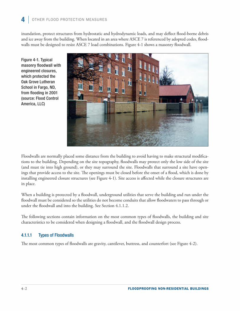
4-2 FLOODPROOFING NON-RESIDENTIAL BUILDINGS
4 OTHER FLOOD PROTECTION MEASURES
inundation, protect structures from hydrostatic and hydrodynamic loads, and may deflect flood-borne debris and ice away from the building. When located in an area where ASCE 7 is referenced by adopted codes, flood-walls must be designed to resist ASCE 7 load combinations. Figure 4-1 shows a masonry floodwall.
Floodwalls are normally placed some distance from the building to avoid having to make structural modifica-tions to the building. Depending on the site topography, floodwalls may protect only the low side of the site (and must tie into high ground), or they may surround the site. Floodwalls that surround a site have open-ings that provide access to the site. The openings must be closed before the onset of a flood, which is done by installing engineered closure structures (see Figure 4-1). Site access is affected while the closure structures are in place.
When a building is protected by a floodwall, underground utilities that serve the building and run under the floodwall must be considered so the utilities do not become conduits that allow floodwaters to pass through or under the floodwall and into the building. See Section 4.1.1.2.
The following sections contain information on the most common types of floodwalls, the building and site characteristics to be considered when designing a floodwall, and the floodwall design process.
4.1.1.1 Types of Floodwalls
The most common types of floodwalls are gravity, cantilever, buttress, and counterfort (see Figure 4-2).
Figure 4-1. Typical masonry floodwall with engineered closures, which protected the Oak Grove Lutheran School in Fargo, ND, from flooding in 2001 (source: Flood Control America, LLC)
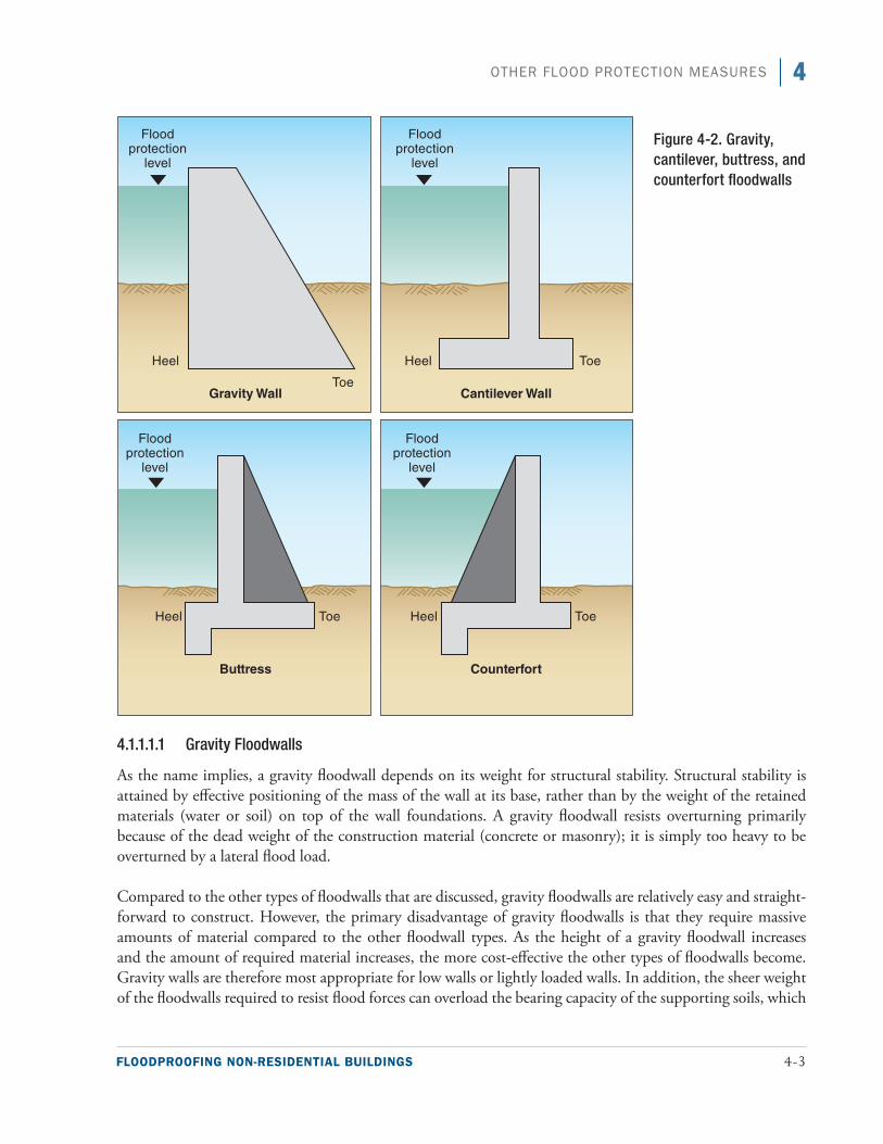
FLOODPROOFING NON-RESIDENTIAL BUILDINGS 4-3
4OTHER FLOOD PROTECTION MEASURES
4.1.1.1.1 Gravity Floodwalls
As the name implies, a gravity floodwall depends on its weight for structural stability. Structural stability is attained by effective positioning of the mass of the wall at its base, rather than by the weight of the retained materials (water or soil) on top of the wall foundations. A gravity floodwall resists overturning primarily because of the dead weight of the construction material (concrete or masonry); it is simply too heavy to be overturned by a lateral flood load.
Compared to the other types of floodwalls that are discussed, gravity floodwalls are relatively easy and straight-forward to construct. However, the primary disadvantage of gravity floodwalls is that they require massive amounts of material compared to the other floodwall types. As the height of a gravity floodwall increases and the amount of required material increases, the more cost-effective the other types of floodwalls become. Gravity walls are therefore most appropriate for low walls or lightly loaded walls. In addition, the sheer weight of the floodwalls required to resist flood forces can overload the bearing capacity of the supporting soils, which
Figure 4-2. Gravity, cantilever, buttress, and counterfort floodwalls
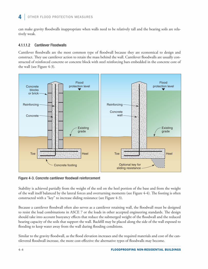
4-4 FLOODPROOFING NON-RESIDENTIAL BUILDINGS
4 OTHER FLOOD PROTECTION MEASURES
can make gravity floodwalls inappropriate when walls need to be relatively tall and the bearing soils are rela-tively weak.
4.1.1.1.2 Cantilever Floodwalls
Cantilever floodwalls are the most common type of floodwall because they are economical to design and construct. They use cantilever action to retain the mass behind the wall. Cantilever floodwalls are usually con-structed of reinforced concrete or concrete block with steel reinforcing bars embedded in the concrete core of the wall (see Figure 4-3).
Figure 4-3. Concrete cantilever floodwall reinforcement
Stability is achieved partially from the weight of the soil on the heel portion of the base and from the weight of the wall itself balanced by the lateral forces and overturning moments (see Figure 4-4). The footing is often constructed with a “key” to increase sliding resistance (see Figure 4-3).
Because a cantilever floodwall often also serves as a cantilever retaining wall, the floodwall must be designed to resist the load combinations in ASCE 7 or the loads in other accepted engineering standards. The design should take into account buoyancy effects that reduce the submerged weight of the floodwall and the reduced bearing capacity of the soils that support the wall. Backfill may be placed along the side of the wall exposed to flooding to keep water away from the wall during flooding conditions.
Similar to the gravity floodwall, as the flood elevation increases and the required materials and cost of the can-tilevered floodwall increase, the more cost-effective the alternative types of floodwalls may become.
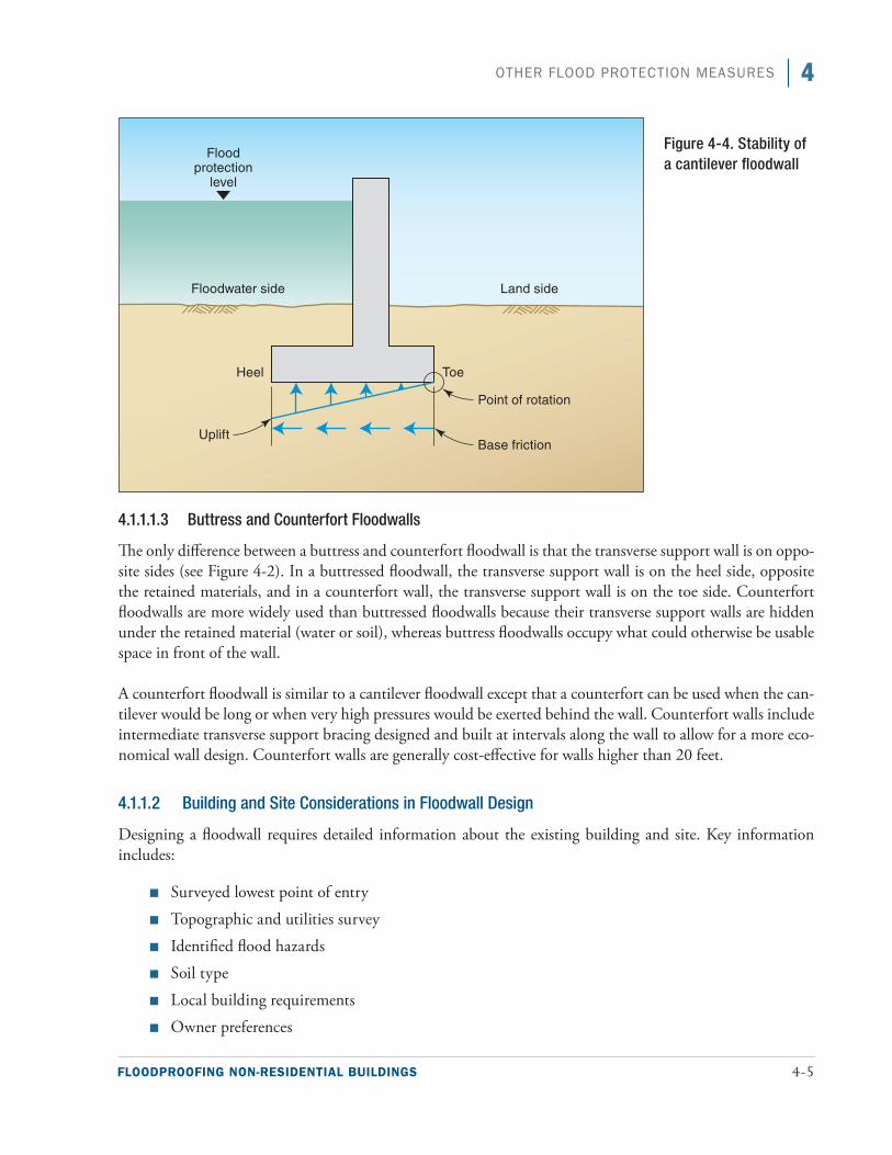
FLOODPROOFING NON-RESIDENTIAL BUILDINGS 4-5
4OTHER FLOOD PROTECTION MEASURES
4.1.1.1.3 Buttress and Counterfort Floodwalls
The only difference between a buttress and counterfort floodwall is that the transverse support wall is on oppo-site sides (see Figure 4-2). In a buttressed floodwall, the transverse support wall is on the heel side, opposite the retained materials, and in a counterfort wall, the transverse support wall is on the toe side. Counterfort floodwalls are more widely used than buttressed floodwalls because their transverse support walls are hidden under the retained material (water or soil), whereas buttress floodwalls occupy what could otherwise be usable space in front of the wall.
A counterfort floodwall is similar to a cantilever floodwall except that a counterfort can be used when the can-tilever would be long or when very high pressures would be exerted behind the wall. Counterfort walls include intermediate transverse support bracing designed and built at intervals along the wall to allow for a more eco-nomical wall design. Counterfort walls are generally cost-effective for walls higher than 20 feet.
4.1.1.2 Building and Site Considerations in Floodwall Design
Designing a floodwall requires detailed information about the existing building and site. Key information includes:
■■ Surveyed lowest point of entry
■■ Topographic and utilities survey
■■ Identified flood hazards
■■ Soil type
■■ Local building requirements
■■ Owner preferences
Figure 4-4. Stability of a cantilever floodwall
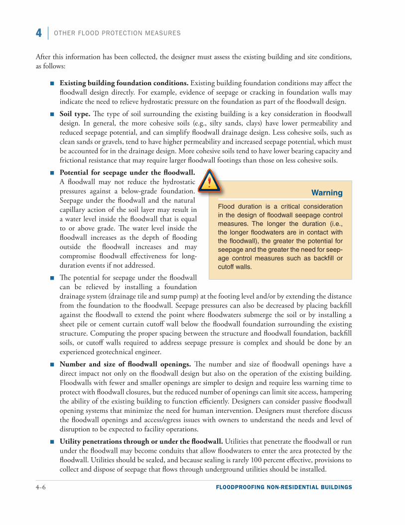
4-6 FLOODPROOFING NON-RESIDENTIAL BUILDINGS
4 OTHER FLOOD PROTECTION MEASURES
After this information has been collected, the designer must assess the existing building and site conditions, as follows:
■■ Existing building foundation conditions. Existing building foundation conditions may affect the floodwall design directly. For example, evidence of seepage or cracking in foundation walls may indicate the need to relieve hydrostatic pressure on the foundation as part of the floodwall design.
■■ Soil type. The type of soil surrounding the existing building is a key consideration in floodwall design. In general, the more cohesive soils (e.g., silty sands, clays) have lower permeability and reduced seepage potential, and can simplify floodwall drainage design. Less cohesive soils, such as clean sands or gravels, tend to have higher permeability and increased seepage potential, which must be accounted for in the drainage design. More cohesive soils tend to have lower bearing capacity and frictional resistance that may require larger floodwall footings than those on less cohesive soils.
■■ Potential for seepage under the floodwall. A floodwall may not reduce the hydrostatic pressures against a below-grade foundation. Seepage under the floodwall and the natural capillary action of the soil layer may result in a water level inside the floodwall that is equal to or above grade. The water level inside the floodwall increases as the depth of flooding outside the floodwall increases and may compromise floodwall effectiveness for long-duration events if not addressed.
■■ The potential for seepage under the floodwall can be relieved by installing a foundation drainage system (drainage tile and sump pump) at the footing level and/or by extending the distance from the foundation to the floodwall. Seepage pressures can also be decreased by placing backfill against the floodwall to extend the point where floodwaters submerge the soil or by installing a sheet pile or cement curtain cutoff wall below the floodwall foundation surrounding the existing structure. Computing the proper spacing between the structure and floodwall foundation, backfill soils, or cutoff walls required to address seepage pressure is complex and should be done by an experienced geotechnical engineer.
■■ Number and size of floodwall openings. The number and size of floodwall openings have a direct impact not only on the floodwall design but also on the operation of the existing building. Floodwalls with fewer and smaller openings are simpler to design and require less warning time to protect with floodwall closures, but the reduced number of openings can limit site access, hampering the ability of the existing building to function efficiently. Designers can consider passive floodwall opening systems that minimize the need for human intervention. Designers must therefore discuss the floodwall openings and access/egress issues with owners to understand the needs and level of disruption to be expected to facility operations.
■■ Utility penetrations through or under the floodwall. Utilities that penetrate the floodwall or run under the floodwall may become conduits that allow floodwaters to enter the area protected by the floodwall. Utilities should be sealed, and because sealing is rarely 100 percent effective, provisions to collect and dispose of seepage that flows through underground utilities should be installed.
Warning
Flood duration is a critical consideration in the design of floodwall seepage control measures. The longer the duration (i.e., the longer floodwaters are in contact with the floodwall), the greater the potential for seepage and the greater the need for seep-age control measures such as backfill or cutoff walls.
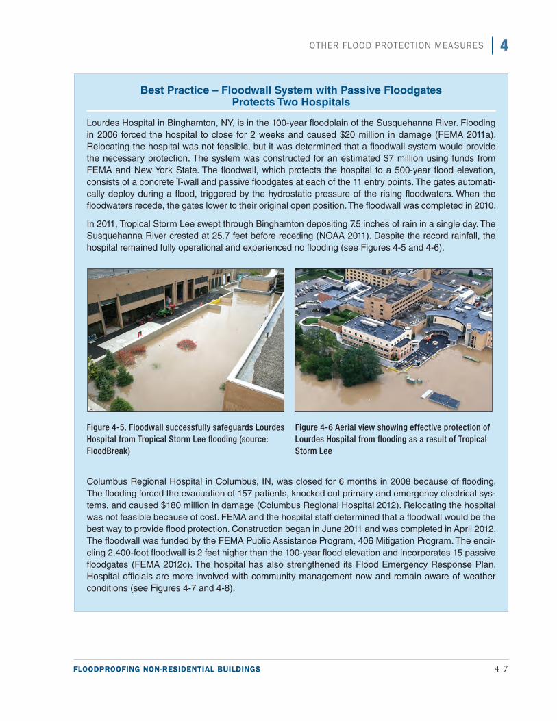
FLOODPROOFING NON-RESIDENTIAL BUILDINGS 4-7
4OTHER FLOOD PROTECTION MEASURES
Best Practice – Floodwall System with Passive Floodgates Protects Two Hospitals
Lourdes Hospital in Binghamton, NY, is in the 100-year floodplain of the Susquehanna River. Flooding in 2006 forced the hospital to close for 2 weeks and caused $20 million in damage (FEMA 2011a). Relocating the hospital was not feasible, but it was determined that a floodwall system would provide the necessary protection. The system was constructed for an estimated $7 million using funds from FEMA and New York State. The floodwall, which protects the hospital to a 500-year flood elevation, consists of a concrete T-wall and passive floodgates at each of the 11 entry points. The gates automati-cally deploy during a flood, triggered by the hydrostatic pressure of the rising floodwaters. When the floodwaters recede, the gates lower to their original open position. The floodwall was completed in 2010.
In 2011, Tropical Storm Lee swept through Binghamton depositing 7.5 inches of rain in a single day. The Susquehanna River crested at 25.7 feet before receding (NOAA 2011). Despite the record rainfall, the hospital remained fully operational and experienced no flooding (see Figures 4-5 and 4-6).
Columbus Regional Hospital in Columbus, IN, was closed for 6 months in 2008 because of flooding. The flooding forced the evacuation of 157 patients, knocked out primary and emergency electrical sys-tems, and caused $180 million in damage (Columbus Regional Hospital 2012). Relocating the hospital was not feasible because of cost. FEMA and the hospital staff determined that a floodwall would be the best way to provide flood protection. Construction began in June 2011 and was completed in April 2012. The floodwall was funded by the FEMA Public Assistance Program, 406 Mitigation Program. The encir-cling 2,400-foot floodwall is 2 feet higher than the 100-year flood elevation and incorporates 15 passive floodgates (FEMA 2012c). The hospital has also strengthened its Flood Emergency Response Plan. Hospital officials are more involved with community management now and remain aware of weather conditions (see Figures 4-7 and 4-8).
Figure 4-5. Floodwall successfully safeguards Lourdes Hospital from Tropical Storm Lee flooding (source: FloodBreak)
Figure 4-6 Aerial view showing effective protection of Lourdes Hospital from flooding as a result of Tropical Storm Lee
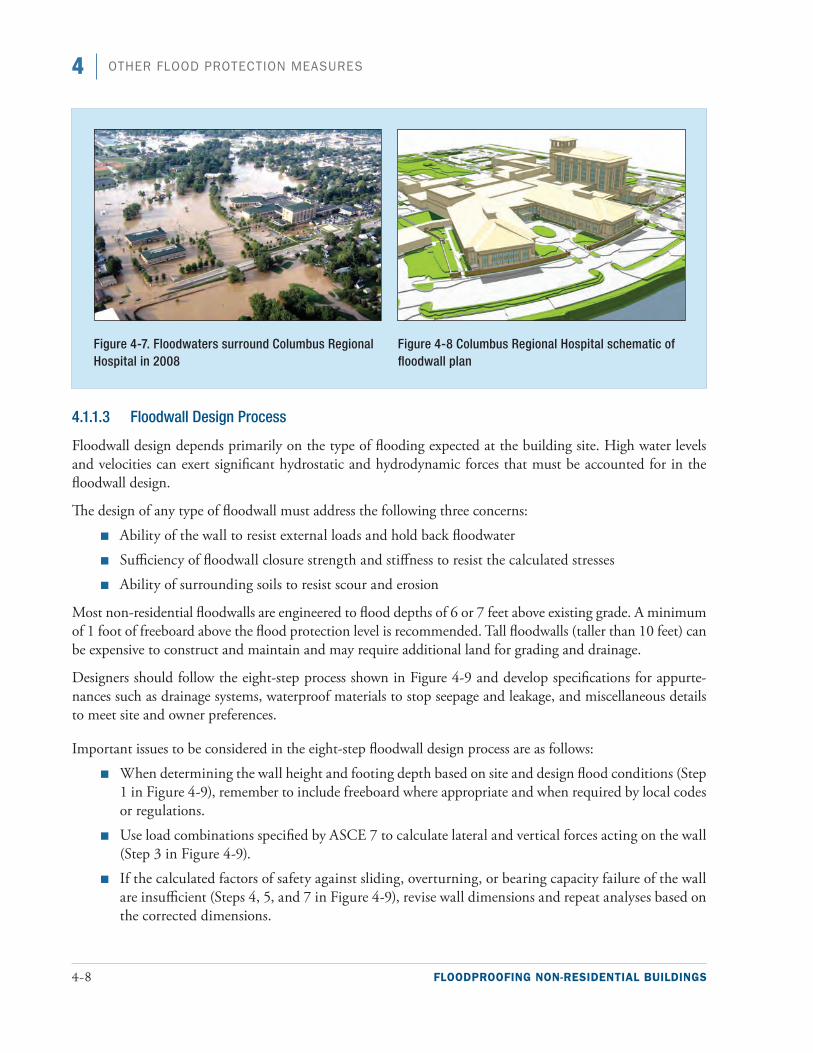
4-8 FLOODPROOFING NON-RESIDENTIAL BUILDINGS
4 OTHER FLOOD PROTECTION MEASURES
4.1.1.3 Floodwall Design Process
Floodwall design depends primarily on the type of flooding expected at the building site. High water levels and velocities can exert significant hydrostatic and hydrodynamic forces that must be accounted for in the floodwall design.
The design of any type of floodwall must address the following three concerns:
■■ Ability of the wall to resist external loads and hold back floodwater
■■ Sufficiency of floodwall closure strength and stiffness to resist the calculated stresses
■■ Ability of surrounding soils to resist scour and erosion
Most non-residential floodwalls are engineered to flood depths of 6 or 7 feet above existing grade. A minimum of 1 foot of freeboard above the flood protection level is recommended. Tall floodwalls (taller than 10 feet) can be expensive to construct and maintain and may require additional land for grading and drainage.
Designers should follow the eight-step process shown in Figure 4-9 and develop specifications for appurte-nances such as drainage systems, waterproof materials to stop seepage and leakage, and miscellaneous details to meet site and owner preferences.
Important issues to be considered in the eight-step floodwall design process are as follows:
■■ When determining the wall height and footing depth based on site and design flood conditions (Step 1 in Figure 4-9), remember to include freeboard where appropriate and when required by local codes or regulations.
■■ Use load combinations specified by ASCE 7 to calculate lateral and vertical forces acting on the wall (Step 3 in Figure 4-9).
■■ If the calculated factors of safety against sliding, overturning, or bearing capacity failure of the wall are insufficient (Steps 4, 5, and 7 in Figure 4-9), revise wall dimensions and repeat analyses based on the corrected dimensions.
Figure 4-7. Floodwaters surround Columbus Regional Hospital in 2008
Figure 4-8 Columbus Regional Hospital schematic of floodwall plan
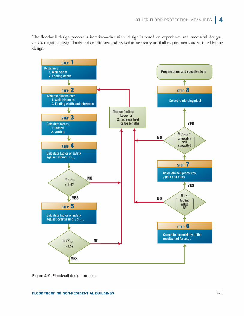
FLOODPROOFING NON-RESIDENTIAL BUILDINGS 4-9
4OTHER FLOOD PROTECTION MEASURES
The floodwall design process is iterative—the initial design is based on experience and successful designs, checked against design loads and conditions, and revised as necessary until all requirements are satisfied by the design.
Figure 4-9. Floodwall design process
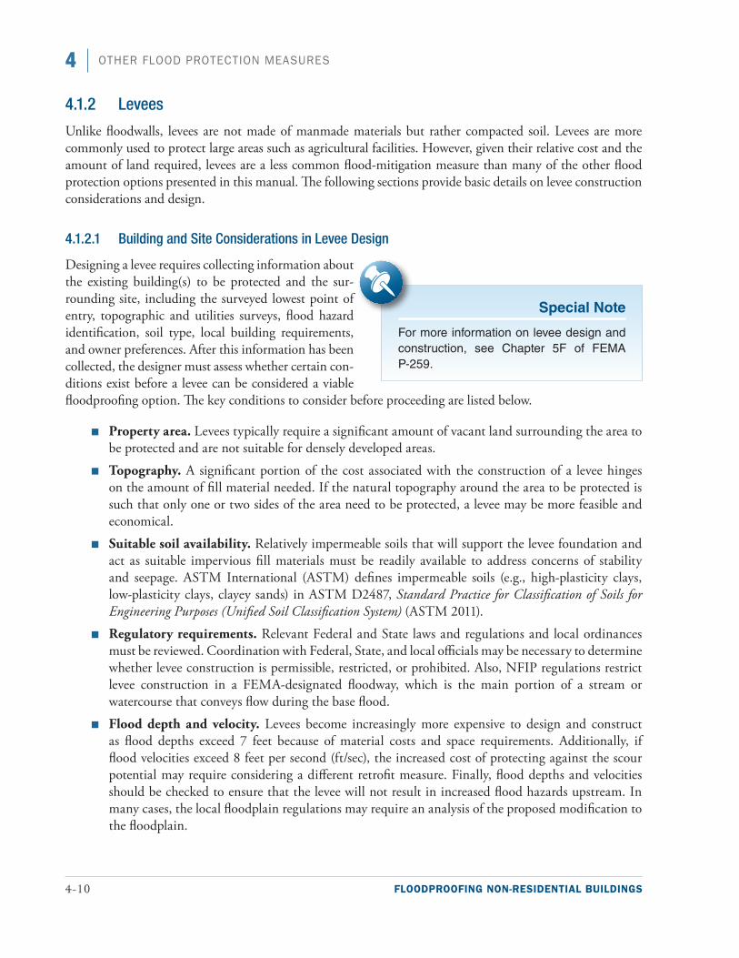
4-10 FLOODPROOFING NON-RESIDENTIAL BUILDINGS
4 OTHER FLOOD PROTECTION MEASURES
4.1.2 Levees
Unlike floodwalls, levees are not made of manmade materials but rather compacted soil. Levees are more commonly used to protect large areas such as agricultural facilities. However, given their relative cost and the amount of land required, levees are a less common flood-mitigation measure than many of the other flood protection options presented in this manual. The following sections provide basic details on levee construction considerations and design.
4.1.2.1 Building and Site Considerations in Levee Design
Designing a levee requires collecting information about the existing building(s) to be protected and the sur-rounding site, including the surveyed lowest point of entry, topographic and utilities surveys, flood hazard identification, soil type, local building requirements, and owner preferences. After this information has been collected, the designer must assess whether certain con-ditions exist before a levee can be considered a viable floodproofing option. The key conditions to consider before proceeding are listed below.
■■ Property area. Levees typically require a significant amount of vacant land surrounding the area to be protected and are not suitable for densely developed areas.
■■ Topography. A significant portion of the cost associated with the construction of a levee hinges on the amount of fill material needed. If the natural topography around the area to be protected is such that only one or two sides of the area need to be protected, a levee may be more feasible and economical.
■■ Suitable soil availability. Relatively impermeable soils that will support the levee foundation and act as suitable impervious fill materials must be readily available to address concerns of stability and seepage. ASTM International (ASTM) defines impermeable soils (e.g., high-plasticity clays, low-plasticity clays, clayey sands) in ASTM D2487, Standard Practice for Classification of Soils for Engineering Purposes (Unified Soil Classification System) (ASTM 2011).
■■ Regulatory requirements. Relevant Federal and State laws and regulations and local ordinances must be reviewed. Coordination with Federal, State, and local officials may be necessary to determine whether levee construction is permissible, restricted, or prohibited. Also, NFIP regulations restrict levee construction in a FEMA-designated floodway, which is the main portion of a stream or watercourse that conveys flow during the base flood.
■■ Flood depth and velocity. Levees become increasingly more expensive to design and construct as flood depths exceed 7 feet because of material costs and space requirements. Additionally, if flood velocities exceed 8 feet per second (ft/sec), the increased cost of protecting against the scour potential may require considering a different retrofit measure. Finally, flood depths and velocities should be checked to ensure that the levee will not result in increased flood hazards upstream. In many cases, the local floodplain regulations may require an analysis of the proposed modification to the floodplain.
Special Note
For more information on levee design and construction, see Chapter 5F of FEMA P-259.
FLOODPROOFING NON-RESIDENTIAL BUILDINGS 4-11
4OTHER FLOOD PROTECTION MEASURES
■■ Seepage potential. Seepage under a levee and the natural capillary action of the soil layer may result in a water level inside the levee that is equal to or above grade and may compromise the levee effectiveness. This condition can be relieved by using an impervious core that extends to the bottom of the inspection trench, installing a drainage toe, and/or extending the distance from the foundation to the levee.
4.1.2.2 Basic Levee Design Parameters
The basic parameters described below help to control levee design costs while providing a conservative design in general accordance with the USACE guidance. The parameters pertain to the design and construction of localized levees for a maximum flood depth of 7 feet. Slope stability analysis and calculation of seepage rates are not addressed. The recommended side slopes are based on experience to satisfy requirements for stability, seepage control, and maintenance. The shear strength of suitable impervious soils compacted to at least 95 per-cent of the Standard Laboratory density as determined in ASTM D698, Standard Test Methods for Laboratory Compaction Characteristics of Soil Using Standard Effort (ASTM 2012), should be adequate to ensure stability of such low levees without the need for laboratory or field testing or extensive calculations.
The basic parameters for crest width and levee side slopes are defined below and illustrated in Figure 4-10. In combination with the toe drainage trench and the cutoff effect provided by backfilling of the inspection trench (Section 4.1.2.3), these parameters should provide sufficient control of seepage and may not require complex analyses.
■■ Maximum settled levee height of 8 to 10 feet. Recommended as the practical limit of levees that protect one or more individual structures based on available space and material costs.
■■ Minimum levee crest width of 10 to 12 feet. Recommended to minimize seepage concerns and allow for ease of construction, vehicle access, and maintenance.
■■ Levee floodwater side slope of 1 vertical to 2.5 horizontal. Recommended to minimize the erosion and scour potential, provide adequate stability under all conditions (including rapid drawdown situations), and facilitate maintenance.
■■ Levee land side slope. May vary based on the levee material. If the material is clayey, a land side slope of 1 vertical to 3 horizontal is acceptable. If the levee material is sandy, a flatter slope of 1 vertical to 5 horizontal is recommended to provide a lower seepage gradient.
Warning
The design parameters for a typical non-residential levee as shown in Figure 4-6 are based on guidance from the USACE and other sources and are intended to be conservative. Alternate parameters for a specific site may be developed by a geo-technical engineer qualified in levee design.
Warning
Duration of flooding is a critical consid-eration in the design of levee seepage control measures. The longer the duration of flooding (i.e., the longer floodwaters are in contact with the levee), the greater the potential for seepage, and the greater the need for seepage control measures such as cutoffs, drainage toes, and impervious cores.
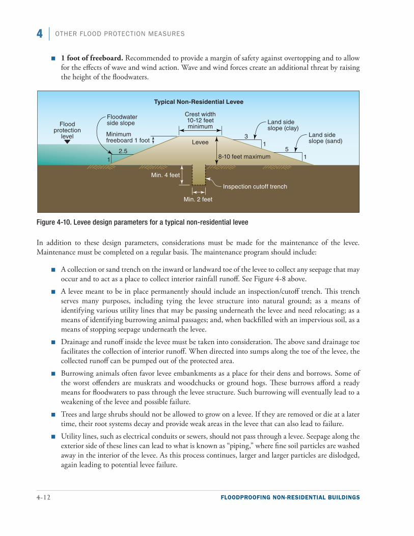
4-12 FLOODPROOFING NON-RESIDENTIAL BUILDINGS
4 OTHER FLOOD PROTECTION MEASURES
■■ 1 foot of freeboard. Recommended to provide a margin of safety against overtopping and to allow for the effects of wave and wind action. Wave and wind forces create an additional threat by raising the height of the floodwaters.
Figure 4-10. Levee design parameters for a typical non-residential levee
In addition to these design parameters, considerations must be made for the maintenance of the levee. Maintenance must be completed on a regular basis. The maintenance program should include:
■■ A collection or sand trench on the inward or landward toe of the levee to collect any seepage that may occur and to act as a place to collect interior rainfall runoff. See Figure 4-8 above.
■■ A levee meant to be in place permanently should include an inspection/cutoff trench. This trench serves many purposes, including tying the levee structure into natural ground; as a means of identifying various utility lines that may be passing underneath the levee and need relocating; as a means of identifying burrowing animal passages; and, when backfilled with an impervious soil, as a means of stopping seepage underneath the levee.
■■ Drainage and runoff inside the levee must be taken into consideration. The above sand drainage toe facilitates the collection of interior runoff. When directed into sumps along the toe of the levee, the collected runoff can be pumped out of the protected area.
■■ Burrowing animals often favor levee embankments as a place for their dens and borrows. Some of the worst offenders are muskrats and woodchucks or ground hogs. These burrows afford a ready means for floodwaters to pass through the levee structure. Such burrowing will eventually lead to a weakening of the levee and possible failure.
■■ Trees and large shrubs should not be allowed to grow on a levee. If they are removed or die at a later time, their root systems decay and provide weak areas in the levee that can also lead to failure.
■■ Utility lines, such as electrical conduits or sewers, should not pass through a levee. Seepage along the exterior side of these lines can lead to what is known as “piping,” where fine soil particles are washed away in the interior of the levee. As this process continues, larger and larger particles are dislodged, again leading to potential levee failure.
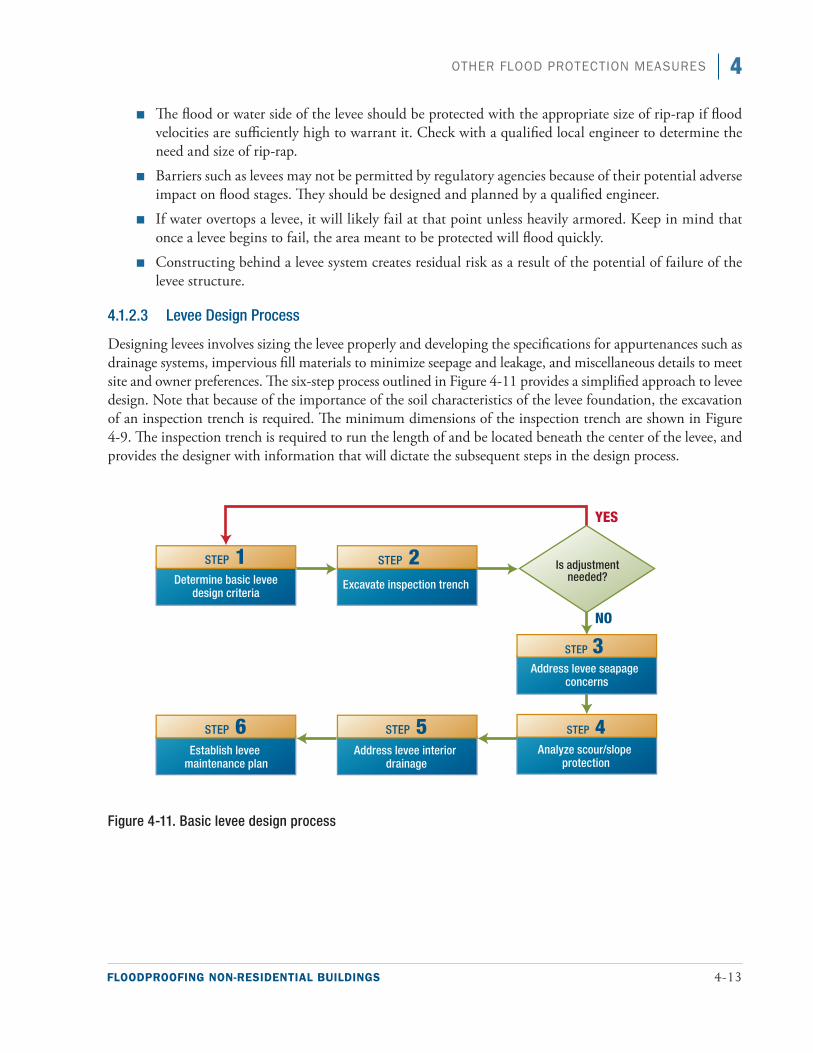
FLOODPROOFING NON-RESIDENTIAL BUILDINGS 4-13
4OTHER FLOOD PROTECTION MEASURES
■■ The flood or water side of the levee should be protected with the appropriate size of rip-rap if flood velocities are sufficiently high to warrant it. Check with a qualified local engineer to determine the need and size of rip-rap.
■■ Barriers such as levees may not be permitted by regulatory agencies because of their potential adverse impact on flood stages. They should be designed and planned by a qualified engineer.
■■ If water overtops a levee, it will likely fail at that point unless heavily armored. Keep in mind that once a levee begins to fail, the area meant to be protected will flood quickly.
■■ Constructing behind a levee system creates residual risk as a result of the potential of failure of the levee structure.
4.1.2.3 Levee Design Process
Designing levees involves sizing the levee properly and developing the specifications for appurtenances such as drainage systems, impervious fill materials to minimize seepage and leakage, and miscellaneous details to meet site and owner preferences. The six-step process outlined in Figure 4-11 provides a simplified approach to levee design. Note that because of the importance of the soil characteristics of the levee foundation, the excavation of an inspection trench is required. The minimum dimensions of the inspection trench are shown in Figure 4-9. The inspection trench is required to run the length of and be located beneath the center of the levee, and provides the designer with information that will dictate the subsequent steps in the design process.
Figure 4-11. Basic levee design process
4-14 FLOODPROOFING NON-RESIDENTIAL BUILDINGS
4 OTHER FLOOD PROTECTION MEASURES
4.2 Wet Floodproofing MeasuresUnlike dry floodproofing, permanent floodwalls and levees, and emergency floodproofing measures (see Section 4.4), wet floodproofing involves modifying a building to allow floodwaters to enter it in order to mini-mize damage to the building. Wet floodproofing involves the following:
Using flood damage-resistant materials below the DFE throughout the building
■■ Raising utilities and important contents to or above the flood protection level
■■ Installing and configuring electrical and mechanical systems to minimize disruptions and facilitate repairs
■■ Installing flood openings or other methods to equalize the hydrostatic pressure exerted by floodwaters
■■ Installing pumps to gradually remove floodwater from basement areas after the flood
The following subsections provide details on the most common wet floodproofing measures. More informa-tion is available in NFIP Technical Bulletin 7-93, Wet Floodproofing Requirements (FEMA 1993b).
4.2.1 Flood Damage-Resistant Materials
Using flood damage-resistant materials can help reduce flood damage and facilitate cleanup to allow buildings to restore service as quickly as possible. Interior building elements such as wall finishes, floors, ceilings, roofs, and building envelope openings can suffer significant damage from inundation by floodwaters, which can lead to failure or unsanitary conditions. The exterior cladding of a building subject to flooding should be nonpo-rous, resistant to chemical corrosion or debris deposits, and conducive to easy cleaning. Interior finishes should be easy to clean and not susceptible to damage from inundation. Likewise, floors, ceilings, roofs, fasteners, gas-kets, connectors, and building envelope openings should be constructed of flood damage-resistant materials to minimize damage during and after inundation.
A detailed list of appropriate flood damage-resistant materials can be found in NFIP Technical Bulletin 2, Flood Damage-Resistant Materials Requirements for Buildings Located in Special Flood Hazard Areas in Accordance with the National Flood Insurance Program (FEMA 2008a). Technical Bulletin 2 classifies flood damage-resistance of materials as acceptable or unacceptable based on cleanability and water resistance (see Table 4-1).
Warning
NFIP regulations do not permit wet flood-proofing to be used to bring a Substantial Improvement/Damage structure into compliance unless the area to be wet flood-proofed is used solely for parking, building access, or storage (44 CFR § 60.3(c)(5)).
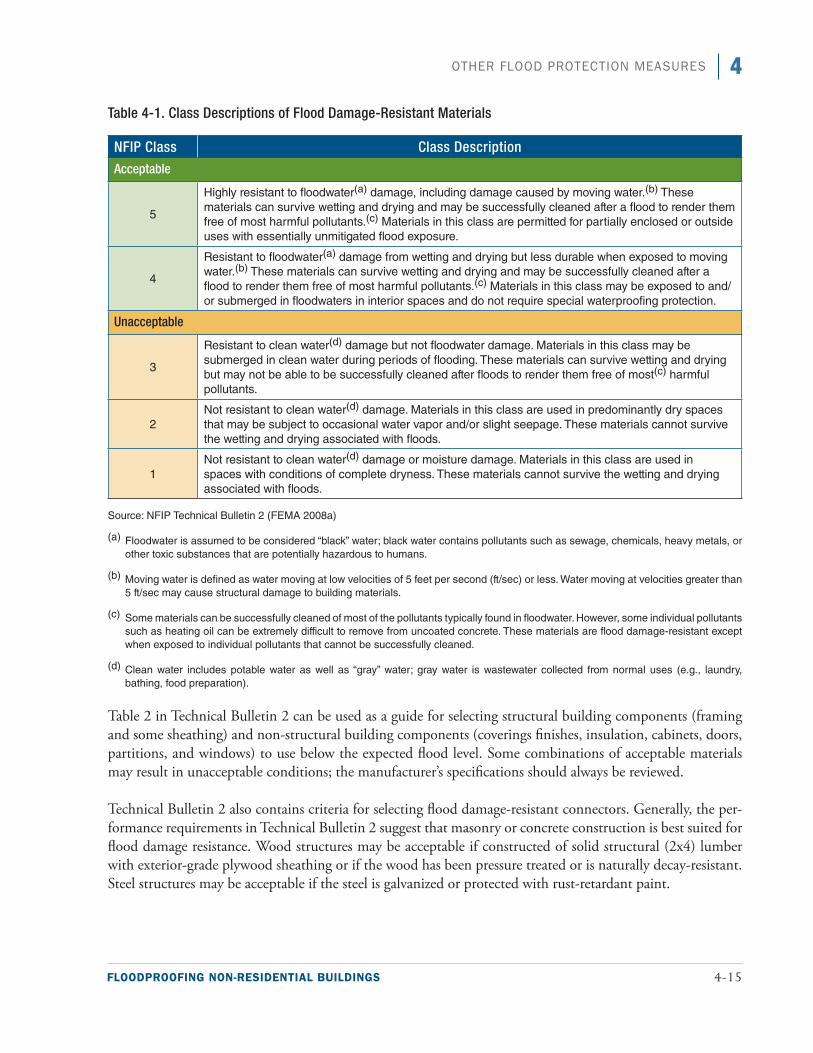
FLOODPROOFING NON-RESIDENTIAL BUILDINGS 4-15
4OTHER FLOOD PROTECTION MEASURES
Table 4-1. Class Descriptions of Flood Damage-Resistant Materials
NFIP Class Class Description
Acceptable
5
Highly resistant to floodwater(a) damage, including damage caused by moving water.(b) These materials can survive wetting and drying and may be successfully cleaned after a flood to render them free of most harmful pollutants.(c) Materials in this class are permitted for partially enclosed or outside uses with essentially unmitigated flood exposure.
4
Resistant to floodwater(a) damage from wetting and drying but less durable when exposed to moving water.(b) These materials can survive wetting and drying and may be successfully cleaned after a flood to render them free of most harmful pollutants.(c) Materials in this class may be exposed to and/or submerged in floodwaters in interior spaces and do not require special waterproofing protection.
Unacceptable
3
Resistant to clean water(d) damage but not floodwater damage. Materials in this class may be submerged in clean water during periods of flooding. These materials can survive wetting and drying but may not be able to be successfully cleaned after floods to render them free of most(c) harmful pollutants.
2Not resistant to clean water(d) damage. Materials in this class are used in predominantly dry spaces that may be subject to occasional water vapor and/or slight seepage. These materials cannot survive the wetting and drying associated with floods.
1 Not resistant to clean water(d) damage or moisture damage. Materials in this class are used in spaces with conditions of complete dryness. These materials cannot survive the wetting and drying associated with floods.
Source: NFIP Technical Bulletin 2 (FEMA 2008a)
(a) Floodwater is assumed to be considered “black” water; black water contains pollutants such as sewage, chemicals, heavy metals, or other toxic substances that are potentially hazardous to humans.
(b) Moving water is defined as water moving at low velocities of 5 feet per second (ft/sec) or less. Water moving at velocities greater than 5 ft/sec may cause structural damage to building materials.
(c) Some materials can be successfully cleaned of most of the pollutants typically found in floodwater. However, some individual pollutants such as heating oil can be extremely difficult to remove from uncoated concrete. These materials are flood damage-resistant except when exposed to individual pollutants that cannot be successfully cleaned.
(d) Clean water includes potable water as well as “gray” water; gray water is wastewater collected from normal uses (e.g., laundry, bathing, food preparation).
Table 2 in Technical Bulletin 2 can be used as a guide for selecting structural building components (framing and some sheathing) and non-structural building components (coverings finishes, insulation, cabinets, doors, partitions, and windows) to use below the expected flood level. Some combinations of acceptable materials may result in unacceptable conditions; the manufacturer’s specifications should always be reviewed.
Technical Bulletin 2 also contains criteria for selecting flood damage-resistant connectors. Generally, the per-formance requirements in Technical Bulletin 2 suggest that masonry or concrete construction is best suited for flood damage resistance. Wood structures may be acceptable if constructed of solid structural (2x4) lumber with exterior-grade plywood sheathing or if the wood has been pressure treated or is naturally decay-resistant. Steel structures may be acceptable if the steel is galvanized or protected with rust-retardant paint.
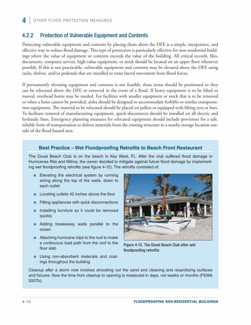
4-16 FLOODPROOFING NON-RESIDENTIAL BUILDINGS
4 OTHER FLOOD PROTECTION MEASURES
4.2.2 Protection of Vulnerable Equipment and Contents
Protecting vulnerable equipment and contents by placing them above the DFE is a simple, inexpensive, and effective way to reduce flood damage. This type of protection is particularly effective for non-residential build-ings where the value of equipment or contents exceeds the value of the building. All critical records, files, documents, computer servers, high-value equipment, or stock should be located on an upper floor whenever possible. If this is not practicable, vulnerable equipment and contents may be elevated above the DFE using racks, shelves, and/or pedestals that are installed to resist lateral movement from flood forces.
If permanently elevating equipment and contents is not feasible, these items should be positioned so they can be relocated above the DFE or removed in the event of a flood. If heavy equipment is to be lifted or moved, overhead hoists may be needed. For facilities with smaller equipment or stock that is to be removed or when a hoist cannot be provided, aisles should be designed to accommodate forklifts or similar transporta-tion equipment. The material to be relocated should be placed on pallets or equipped with lifting eyes or bars. To facilitate removal of manufacturing equipment, quick disconnects should be installed on all electric and hydraulic lines. Emergency planning measures for relocated equipment should include provisions for a safe, reliable form of transportation to deliver materials from the existing structure to a nearby storage location out-side of the flood hazard area.
Best Practice – Wet Floodproofing Retrofits to Beach Front Restaurant
The Duval Beach Club is on the beach in Key West, FL. After the club suffered flood damage in Hurricanes Rita and Wilma, the owner decided to mitigate against future flood damage by implement-ing wet floodproofing retrofits (see figure 4-12). The retrofits consisted of:
■ Elevating the electrical system by running wiring along the top of the walls, down to each outlet
■ Locating outlets 42 inches above the floor
■ Fitting appliances with quick disconnections
■ Installing furniture so it could be removed quickly
■ Adding breakaway walls parallel to the ocean
■ Attaching hurricane clips to the roof to make a continuous load path from the roof to the floor slab
■ Using non-absorbent materials and coat-ings throughout the building
Cleanup after a storm now involves shoveling out the sand and cleaning and resanitizing surfaces and fixtures. Now the time from cleanup to opening is measured in days, not weeks or months (FEMA 2007b).
Figure 4-12. The Duval Beach Club after wet floodproofing retrofits
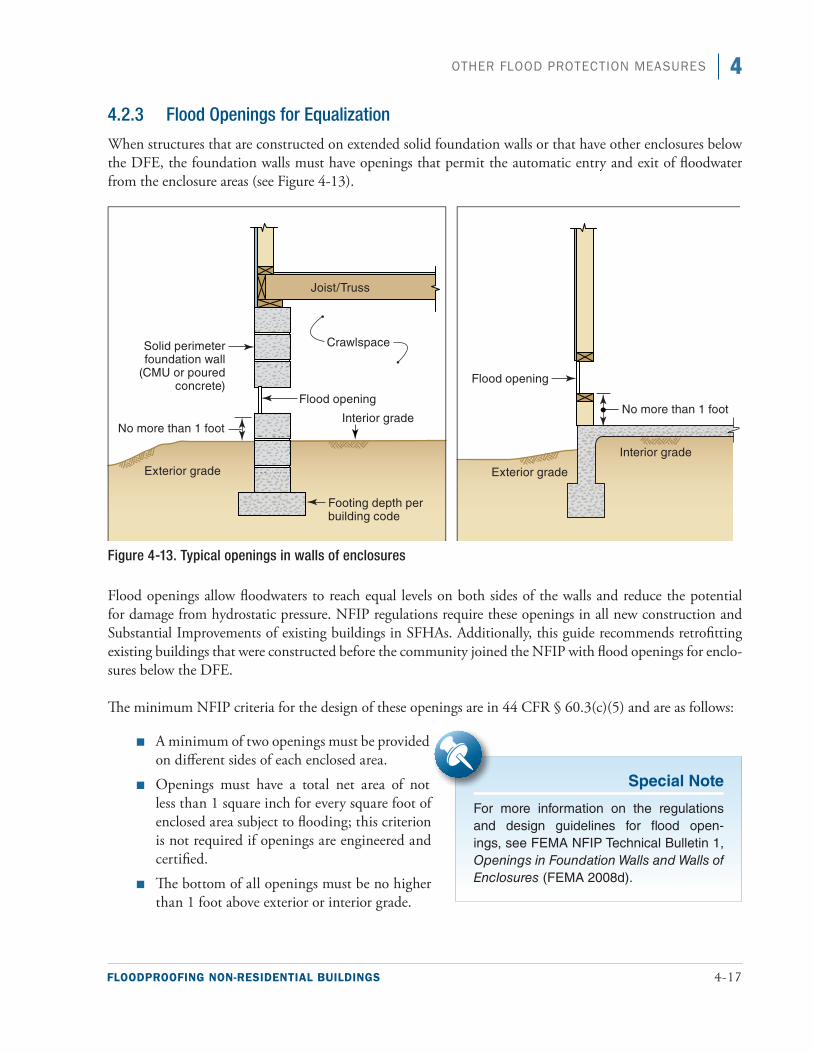
FLOODPROOFING NON-RESIDENTIAL BUILDINGS 4-17
4OTHER FLOOD PROTECTION MEASURES
4.2.3 Flood Openings for Equalization
When structures that are constructed on extended solid foundation walls or that have other enclosures below the DFE, the foundation walls must have openings that permit the automatic entry and exit of floodwater from the enclosure areas (see Figure 4-13).
Figure 4-13. Typical openings in walls of enclosures
Flood openings allow floodwaters to reach equal levels on both sides of the walls and reduce the potential for damage from hydrostatic pressure. NFIP regulations require these openings in all new construction and Substantial Improvements of existing buildings in SFHAs. Additionally, this guide recommends retrofitting existing buildings that were constructed before the community joined the NFIP with flood openings for enclo-sures below the DFE.
The minimum NFIP criteria for the design of these openings are in 44 CFR § 60.3(c)(5) and are as follows:
■■ A minimum of two openings must be provided on different sides of each enclosed area.
■■ Openings must have a total net area of not less than 1 square inch for every square foot of enclosed area subject to flooding; this criterion is not required if openings are engineered and certified.
■■ The bottom of all openings must be no higher than 1 foot above exterior or interior grade.
Special Note
For more information on the regulations and design guidelines for flood open-ings, see FEMA NFIP Technical Bulletin 1, Openings in Foundation Walls and Walls of Enclosures (FEMA 2008d).
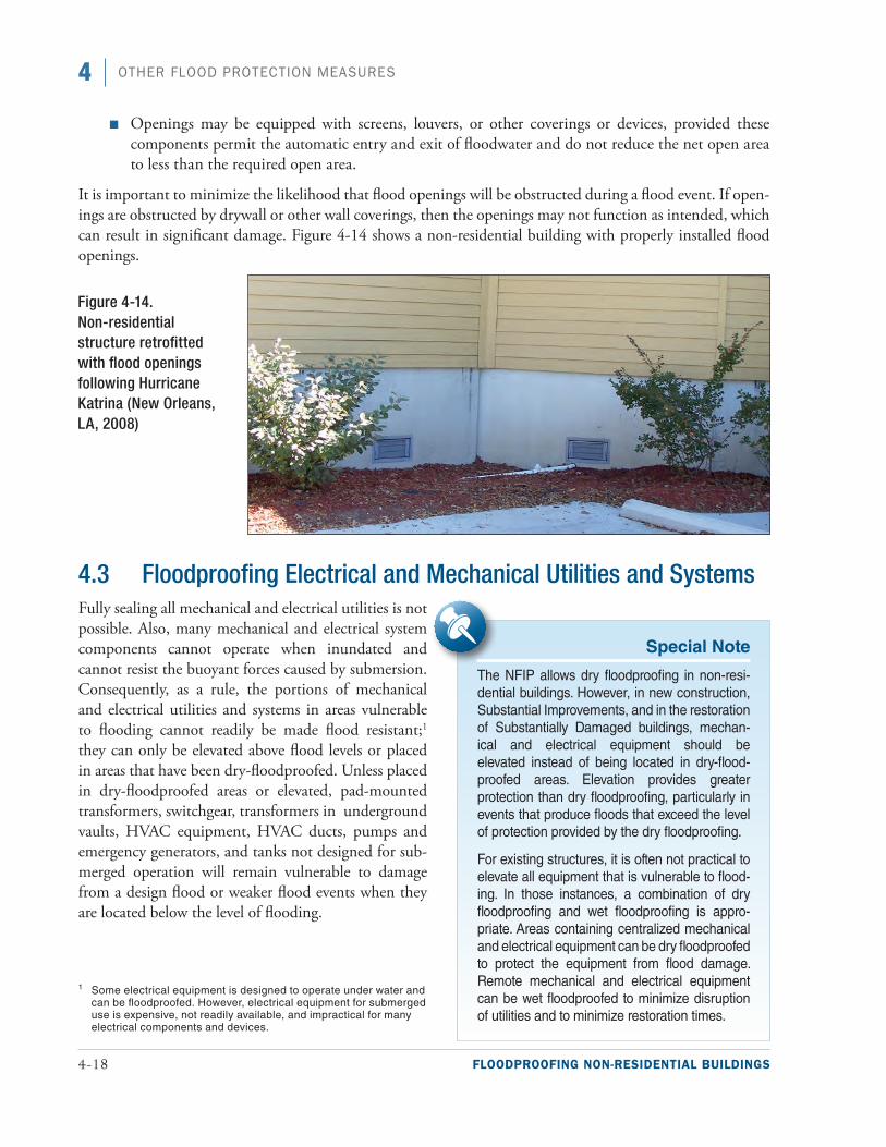
4-18 FLOODPROOFING NON-RESIDENTIAL BUILDINGS
4 OTHER FLOOD PROTECTION MEASURES
■■ Openings may be equipped with screens, louvers, or other coverings or devices, provided these components permit the automatic entry and exit of floodwater and do not reduce the net open area to less than the required open area.
It is important to minimize the likelihood that flood openings will be obstructed during a flood event. If open-ings are obstructed by drywall or other wall coverings, then the openings may not function as intended, which can result in significant damage. Figure 4-14 shows a non-residential building with properly installed flood openings.
4.3 Floodproofing Electrical and Mechanical Utilities and Systems Fully sealing all mechanical and electrical utilities is not possible. Also, many mechanical and electrical system components cannot operate when inundated and cannot resist the buoyant forces caused by submersion. Consequently, as a rule, the portions of mechanical and electrical utilities and systems in areas vulnerable to flooding cannot readily be made flood resistant;1 they can only be elevated above flood levels or placed in areas that have been dry-floodproofed. Unless placed in dry-floodproofed areas or elevated, pad-mounted transformers, switchgear, transformers in underground vaults, HVAC equipment, HVAC ducts, pumps and emergency generators, and tanks not designed for sub-merged operation will remain vulnerable to damage from a design flood or weaker flood events when they are located below the level of flooding.
Figure 4-14. Non-residential structure retrofitted with flood openings following Hurricane Katrina (New Orleans, LA, 2008)
Special Note
The NFIP allows dry floodproofing in non-resi-dential buildings. However, in new construction, Substantial Improvements, and in the restoration of Substantially Damaged buildings, mechan-ical and electrical equipment should be elevated instead of being located in dry-flood-proofed areas. Elevation provides greater protection than dry floodproofing, particularly in events that produce floods that exceed the level of protection provided by the dry floodproofing.
For existing structures, it is often not practical to elevate all equipment that is vulnerable to flood-ing. In those instances, a combination of dry floodproofing and wet floodproofing is appro-priate. Areas containing centralized mechanical and electrical equipment can be dry floodproofed to protect the equipment from flood damage. Remote mechanical and electrical equipment can be wet floodproofed to minimize disruption of utilities and to minimize restoration times.
1 Some electrical equipment is designed to operate under water and can be floodproofed. However, electrical equipment for submerged use is expensive, not readily available, and impractical for many electrical components and devices.
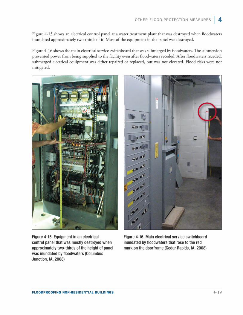
FLOODPROOFING NON-RESIDENTIAL BUILDINGS 4-19
4OTHER FLOOD PROTECTION MEASURES
Figure 4-15 shows an electrical control panel at a water treatment plant that was destroyed when floodwaters inundated approximately two-thirds of it. Most of the equipment in the panel was destroyed.
Figure 4-16 shows the main electrical service switchboard that was submerged by floodwaters. The submersion prevented power from being supplied to the facility even after floodwaters receded. After floodwaters receded, submerged electrical equipment was either repaired or replaced, but was not elevated. Flood risks were not mitigated.
Figure 4-15. Equipment in an electrical control panel that was mostly destroyed when approximately two-thirds of the height of panel was inundated by floodwaters (Columbus Junction, IA, 2008)
Figure 4-16. Main electrical service switchboard inundated by floodwaters that rose to the red mark on the doorframe (Cedar Rapids, IA, 2008)
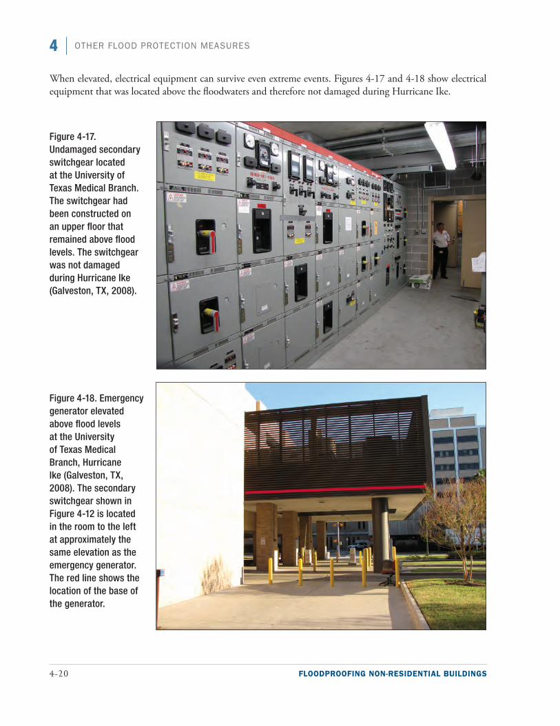
4-20 FLOODPROOFING NON-RESIDENTIAL BUILDINGS
4 OTHER FLOOD PROTECTION MEASURES
When elevated, electrical equipment can survive even extreme events. Figures 4-17 and 4-18 show electrical equipment that was located above the floodwaters and therefore not damaged during Hurricane Ike.
Figure 4-17. Undamaged secondary switchgear located at the University of Texas Medical Branch. The switchgear had been constructed on an upper floor that remained above flood levels. The switchgear was not damaged during Hurricane Ike (Galveston, TX, 2008).
Figure 4-18. Emergency generator elevated above flood levels at the University of Texas Medical Branch, Hurricane Ike (Galveston, TX, 2008). The secondary switchgear shown in Figure 4-12 is located in the room to the left at approximately the same elevation as the emergency generator. The red line shows the location of the base of the generator.
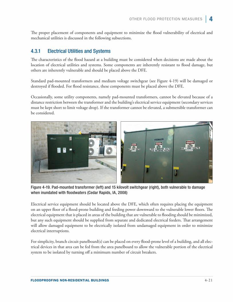
FLOODPROOFING NON-RESIDENTIAL BUILDINGS 4-21
4OTHER FLOOD PROTECTION MEASURES
The proper placement of components and equipment to minimize the flood vulnerability of electrical and mechanical utilities is discussed in the following subsections.
4.3.1 Electrical Utilities and Systems
The characteristics of the flood hazard at a building must be considered when decisions are made about the location of electrical utilities and systems. Some components are inherently resistant to flood damage, but others are inherently vulnerable and should be placed above the DFE.
Standard pad-mounted transformers and medium voltage switchgear (see Figure 4-19) will be damaged or destroyed if flooded. For flood resistance, these components must be placed above the DFE.
Occasionally, some utility components, namely pad-mounted transformers, cannot be elevated because of a distance restriction between the transformer and the building’s electrical service equipment (secondary services must be kept short to limit voltage drop). If the transformer cannot be elevated, a submersible transformer can be considered.
Figure 4-19. Pad-mounted transformer (left) and 15 kilovolt switchgear (right), both vulnerable to damage when inundated with floodwaters (Cedar Rapids, IA, 2008)
Electrical service equipment should be located above the DFE, which often requires placing the equipment on an upper floor of a flood-prone building and feeding power downward to the vulnerable lower floors. The electrical equipment that is placed in areas of the building that are vulnerable to flooding should be minimized, but any such equipment should be supplied from separate and dedicated electrical feeders. That arrangement will allow damaged equipment to be electrically isolated from undamaged equipment in order to minimize electrical interruptions.
For simplicity, branch circuit panelboard(s) can be placed on every flood-prone level of a building, and all elec-trical devices in that area can be fed from the area panelboard to allow the vulnerable portion of the electrical system to be isolated by turning off a minimum number of circuit breakers.
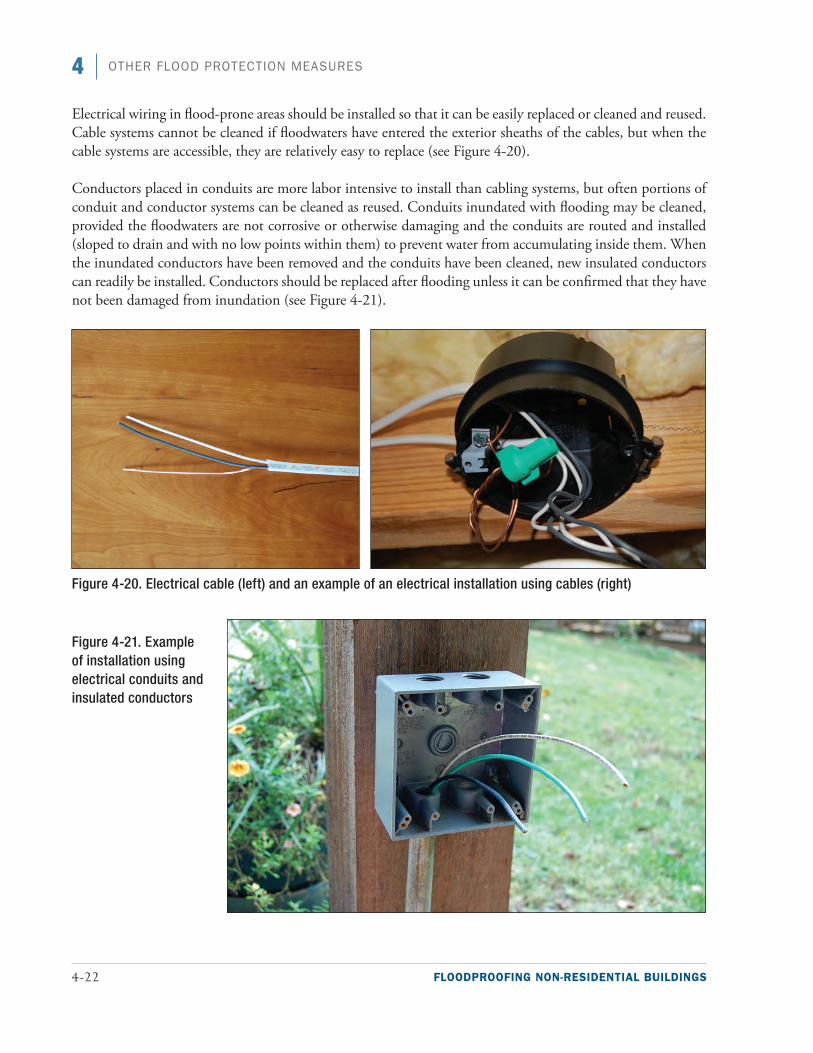
4-22 FLOODPROOFING NON-RESIDENTIAL BUILDINGS
4 OTHER FLOOD PROTECTION MEASURES
Electrical wiring in flood-prone areas should be installed so that it can be easily replaced or cleaned and reused. Cable systems cannot be cleaned if floodwaters have entered the exterior sheaths of the cables, but when the cable systems are accessible, they are relatively easy to replace (see Figure 4-20).
Conductors placed in conduits are more labor intensive to install than cabling systems, but often portions of conduit and conductor systems can be cleaned as reused. Conduits inundated with flooding may be cleaned, provided the floodwaters are not corrosive or otherwise damaging and the conduits are routed and installed (sloped to drain and with no low points within them) to prevent water from accumulating inside them. When the inundated conductors have been removed and the conduits have been cleaned, new insulated conductors can readily be installed. Conductors should be replaced after flooding unless it can be confirmed that they have not been damaged from inundation (see Figure 4-21).
Figure 4-20. Electrical cable (left) and an example of an electrical installation using cables (right)
Figure 4-21. Example of installation using electrical conduits and insulated conductors
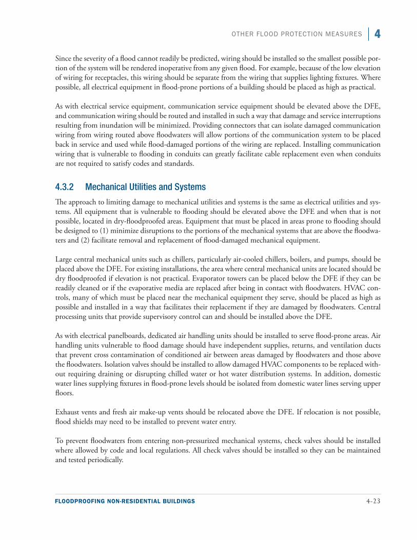
FLOODPROOFING NON-RESIDENTIAL BUILDINGS 4-23
4OTHER FLOOD PROTECTION MEASURES
Since the severity of a flood cannot readily be predicted, wiring should be installed so the smallest possible por-tion of the system will be rendered inoperative from any given flood. For example, because of the low elevation of wiring for receptacles, this wiring should be separate from the wiring that supplies lighting fixtures. Where possible, all electrical equipment in flood-prone portions of a building should be placed as high as practical.
As with electrical service equipment, communication service equipment should be elevated above the DFE, and communication wiring should be routed and installed in such a way that damage and service interruptions resulting from inundation will be minimized. Providing connectors that can isolate damaged communication wiring from wiring routed above floodwaters will allow portions of the communication system to be placed back in service and used while flood-damaged portions of the wiring are replaced. Installing communication wiring that is vulnerable to flooding in conduits can greatly facilitate cable replacement even when conduits are not required to satisfy codes and standards.
4.3.2 Mechanical Utilities and Systems
The approach to limiting damage to mechanical utilities and systems is the same as electrical utilities and sys-tems. All equipment that is vulnerable to flooding should be elevated above the DFE and when that is not possible, located in dry-floodproofed areas. Equipment that must be placed in areas prone to flooding should be designed to (1) minimize disruptions to the portions of the mechanical systems that are above the floodwa-ters and (2) facilitate removal and replacement of flood-damaged mechanical equipment.
Large central mechanical units such as chillers, particularly air-cooled chillers, boilers, and pumps, should be placed above the DFE. For existing installations, the area where central mechanical units are located should be dry floodproofed if elevation is not practical. Evaporator towers can be placed below the DFE if they can be readily cleaned or if the evaporative media are replaced after being in contact with floodwaters. HVAC con-trols, many of which must be placed near the mechanical equipment they serve, should be placed as high as possible and installed in a way that facilitates their replacement if they are damaged by floodwaters. Central processing units that provide supervisory control can and should be installed above the DFE.
As with electrical panelboards, dedicated air handling units should be installed to serve flood-prone areas. Air handling units vulnerable to flood damage should have independent supplies, returns, and ventilation ducts that prevent cross contamination of conditioned air between areas damaged by floodwaters and those above the floodwaters. Isolation valves should be installed to allow damaged HVAC components to be replaced with-out requiring draining or disrupting chilled water or hot water distribution systems. In addition, domestic water lines supplying fixtures in flood-prone levels should be isolated from domestic water lines serving upper floors.
Exhaust vents and fresh air make-up vents should be relocated above the DFE. If relocation is not possible, flood shields may need to be installed to prevent water entry.
To prevent floodwaters from entering non-pressurized mechanical systems, check valves should be installed where allowed by code and local regulations. All check valves should be installed so they can be maintained and tested periodically.
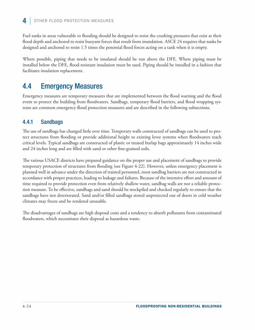
4-24 FLOODPROOFING NON-RESIDENTIAL BUILDINGS
4 OTHER FLOOD PROTECTION MEASURES
Fuel tanks in areas vulnerable to flooding should be designed to resist the crushing pressures that exist at their flood depth and anchored to resist buoyant forces that result from inundation. ASCE 24 requires that tanks be designed and anchored to resist 1.5 times the potential flood forces acting on a tank when it is empty.
Where possible, piping that needs to be insulated should be run above the DFE. Where piping must be installed below the DFE, flood-resistant insulation must be used. Piping should be installed in a fashion that facilitates insulation replacement.
4.4 Emergency MeasuresEmergency measures are temporary measures that are implemented between the flood warning and the flood event to protect the building from floodwaters. Sandbags, temporary flood barriers, and flood wrapping sys-tems are common emergency flood protection measures and are described in the following subsections.
4.4.1 Sandbags
The use of sandbags has changed little over time. Temporary walls constructed of sandbags can be used to pro-tect structures from flooding or provide additional height to existing levee systems when floodwaters reach critical levels. Typical sandbags are constructed of plastic or treated burlap bags approximately 14 inches wide and 24 inches long and are filled with sand or other fine-grained soils.
The various USACE districts have prepared guidance on the proper use and placement of sandbags to provide temporary protection of structures from flooding (see Figure 4-22). However, unless emergency placement is planned well in advance under the direction of trained personnel, most sandbag barriers are not constructed in accordance with proper practices, leading to leakage and failures. Because of the intensive effort and amount of time required to provide protection even from relatively shallow water, sandbag walls are not a reliable protec-tion measure. To be effective, sandbags and sand should be stockpiled and checked regularly to ensure that the sandbags have not deteriorated. Sand and/or filled sandbags stored unprotected out of doors in cold weather climates may freeze and be rendered unusable.
The disadvantages of sandbags are high disposal costs and a tendency to absorb pollutants from contaminated floodwaters, which necessitates their disposal as hazardous waste.
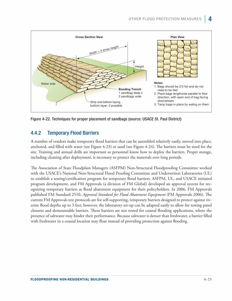
FLOODPROOFING NON-RESIDENTIAL BUILDINGS 4-25
4OTHER FLOOD PROTECTION MEASURES
Figure 4-22. Techniques for proper placement of sandbags (source: USACE St. Paul District)
4.4.2 Temporary Flood Barriers
A number of vendors make temporary flood barriers that can be assembled relatively easily, moved into place, anchored, and filled with water (see Figure 4-23) or sand (see Figure 4-24). The barriers must be sized for the site. Training and annual drills are important so personnel know how to deploy the barriers. Proper storage, including cleaning after deployment, is necessary to protect the materials over long periods.
The Association of State Floodplain Managers (ASFPM) Non-Structural Floodproofing Committee worked with the USACE’s National Non-Structural Flood Proofing Committee and Underwriters Laboratories (UL) to establish a testing/certification program for temporary flood barriers. ASFPM, UL, and USACE initiated program development, and FM Approvals (a division of FM Global) developed an approval system for rec-ognizing temporary barriers as flood abatement equipment for their policyholders. In 2006, FM Approvals published FM Standard 2510, Approval Standard for Flood Abatement Equipment (FM Approvals 2006). The current FM Approvals test protocols are for self-supporting, temporary barriers designed to protect against riv-erine flood depths up to 3 feet; however, the laboratory set-up can be adapted easily to allow for testing panel closures and demountable barriers. These barriers are not tested for coastal flooding applications, where the presence of saltwater may hinder their performance. Because saltwater is denser than freshwater, a barrier filled with freshwater in a coastal location may float instead of providing protection against flooding.
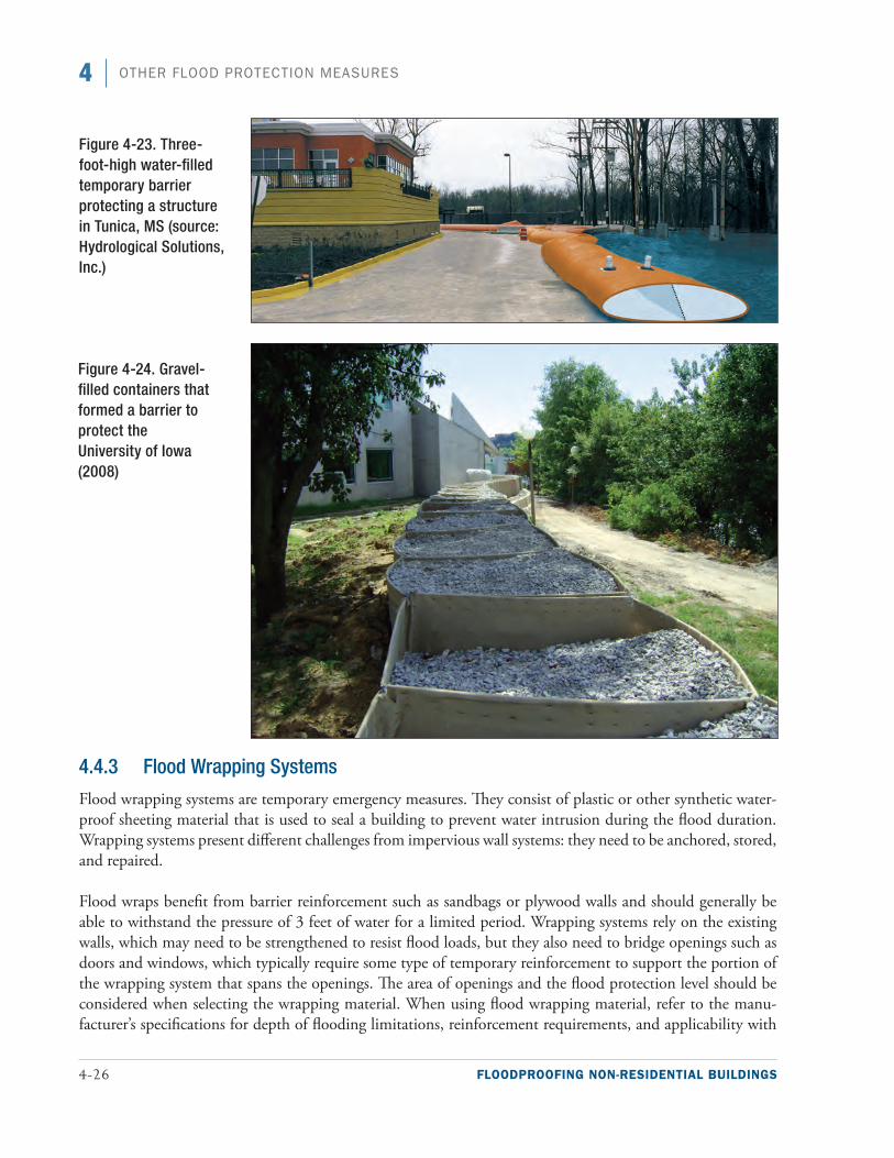
4-26 FLOODPROOFING NON-RESIDENTIAL BUILDINGS
4 OTHER FLOOD PROTECTION MEASURES
4.4.3 Flood Wrapping Systems
Flood wrapping systems are temporary emergency measures. They consist of plastic or other synthetic water-proof sheeting material that is used to seal a building to prevent water intrusion during the flood duration. Wrapping systems present different challenges from impervious wall systems: they need to be anchored, stored, and repaired.
Flood wraps benefit from barrier reinforcement such as sandbags or plywood walls and should generally be able to withstand the pressure of 3 feet of water for a limited period. Wrapping systems rely on the existing walls, which may need to be strengthened to resist flood loads, but they also need to bridge openings such as doors and windows, which typically require some type of temporary reinforcement to support the portion of the wrapping system that spans the openings. The area of openings and the flood protection level should be considered when selecting the wrapping material. When using flood wrapping material, refer to the manu-facturer’s specifications for depth of flooding limitations, reinforcement requirements, and applicability with
Figure 4-24. Gravel-filled containers that formed a barrier to protect the University of Iowa (2008)
Figure 4-23. Three-foot-high water-filled temporary barrier protecting a structure in Tunica, MS (source: Hydrological Solutions, Inc.)
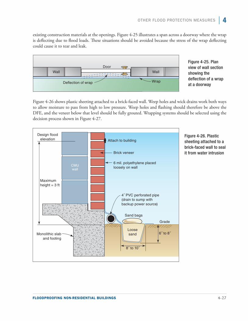
FLOODPROOFING NON-RESIDENTIAL BUILDINGS 4-27
4OTHER FLOOD PROTECTION MEASURES
existing construction materials at the openings. Figure 4-25 illustrates a span across a doorway where the wrap is deflecting due to flood loads. These situations should be avoided because the stress of the wrap deflecting could cause it to tear and leak.
Figure 4-26 shows plastic sheeting attached to a brick-faced wall. Weep holes and wick drains work both ways to allow moisture to pass from high to low pressure. Weep holes and flashing should therefore be above the DFE, and the veneer below that level should be fully grouted. Wrapping systems should be selected using the decision process shown in Figure 4-27.
Figure 4-25. Plan view of wall section showing the deflection of a wrap at a doorway
Figure 4-26. Plastic sheeting attached to a brick-faced wall to seal it from water intrusion
Wall
Deflection of wrap Wrap
DoorWall
Design floodelevation Attach to building
6 mil. polyethylene placed loosely on wall
Brick veneer
Sand bags
Loosesand
Grade
6˝ to 8˝
8˝ to 10˝
Monolithic slaband footing
Maximumheight = 3 ft
CMUwall
4˝ PVC perforated pipe(drain to sump withbackup power source)
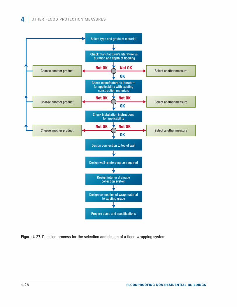
4-28 FLOODPROOFING NON-RESIDENTIAL BUILDINGS
4 OTHER FLOOD PROTECTION MEASURES
Figure 4-27. Decision process for the selection and design of a flood wrapping system
FLOODPROOFING NON-RESIDENTIAL BUILDINGS 4-29
4OTHER FLOOD PROTECTION MEASURES
Wrap systems require secure connections at both the top and bottom of the wrap. The actual loads imposed vertically on the wrap are difficult to determine because they can vary depending on the quality of the instal-lation. Since the intent of flood wrapping systems is to provide floodproofing and not structural support, voids left from poor construction may force the wrap to carry the weight of the water and should be avoided.
The following should be considered when selecting the method to attach the wrap to the building:
■■ The wall attachment system should uniformly support the wrap. Small spacing between the connections and a member with some rigidity on the outside of the wrap can provide the needed support.
■■ The existing wall construction can vary widely. Part of the connection may need to be a permanent part of the wall.
Anchoring wrap into the grade at the base of a wall is the most important link in the wrap system (see Figure 4-24). The following recommendations should be followed during selection and design of a grade connection method:
■■ A drain line connected to a sump pump should be located between the wrap and the building to remove any water that leaks through the wrap or seeps through the soil under the at-grade anchor.
■■ The end of the wrap should be buried at least below the topsoil layer. Additional ballast may be needed (e.g., sandbags, stone) to prevent wrap movement in a saturated or frozen soil condition.
■■ The product literature for the wrap material and applicable codes and standards should be reviewed and followed.
Before the final selection of a wrapping system, the following issues should be addressed by the manufacturer and the instructions should be provided to the owner:
■■ Based on the type of building the wrapping system will be applied to, any issues with chemicals used or stored onsite that could damage the wrapping system should be identified. It is also important for the designer or owner to evaluate adjacent properties to make sure that any potential chemicals that could damage the wrapping system during a flood have been identified.
■■ The manufacturer should provide guidance on how to repair the wrapping system and approximately how much additional wrapping material is required for each repair. It is also important to know whether the wrapping material can be repaired once it has gotten wet or whether it must be dry.
4.5 Combination of Floodproofing MeasuresSome non-residential buildings and site conditions require multiple floodproofing measures for adequate pro-tection. A single floodproofing measure may provide only limited protection or protect only a portion of a single building or group of buildings. In these situations, combining floodproofing measures may be appropri-ate. Combining floodproofing measures is discussed in the following subsections.
Special Note
Wrap systems may be affected by freeze-thaw cycles. Careful evaluation of performance in frozen climates is advisable and installation in accordance with manu-facturer instructions is recommended.
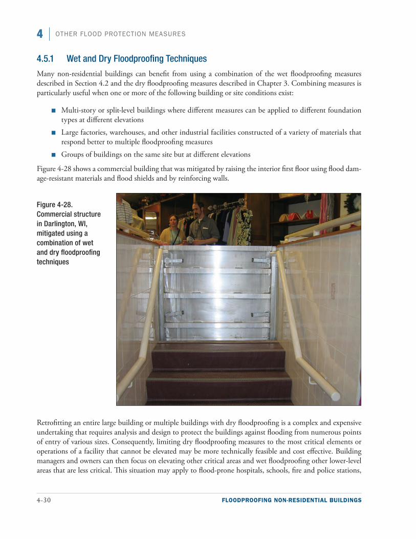
4-30 FLOODPROOFING NON-RESIDENTIAL BUILDINGS
4 OTHER FLOOD PROTECTION MEASURES
4.5.1 Wet and Dry Floodproofing Techniques
Many non-residential buildings can benefit from using a combination of the wet floodproofing measures described in Section 4.2 and the dry floodproofing measures described in Chapter 3. Combining measures is particularly useful when one or more of the following building or site conditions exist:
■■ Multi-story or split-level buildings where different measures can be applied to different foundation types at different elevations
■■ Large factories, warehouses, and other industrial facilities constructed of a variety of materials that respond better to multiple floodproofing measures
■■ Groups of buildings on the same site but at different elevations
Figure 4-28 shows a commercial building that was mitigated by raising the interior first floor using flood dam-age-resistant materials and flood shields and by reinforcing walls.
Retrofitting an entire large building or multiple buildings with dry floodproofing is a complex and expensive undertaking that requires analysis and design to protect the buildings against flooding from numerous points of entry of various sizes. Consequently, limiting dry floodproofing measures to the most critical elements or operations of a facility that cannot be elevated may be more technically feasible and cost effective. Building managers and owners can then focus on elevating other critical areas and wet floodproofing other lower-level areas that are less critical. This situation may apply to flood-prone hospitals, schools, fire and police stations,
Figure 4-28. Commercial structure in Darlington, WI, mitigated using a combination of wet and dry floodproofing techniques
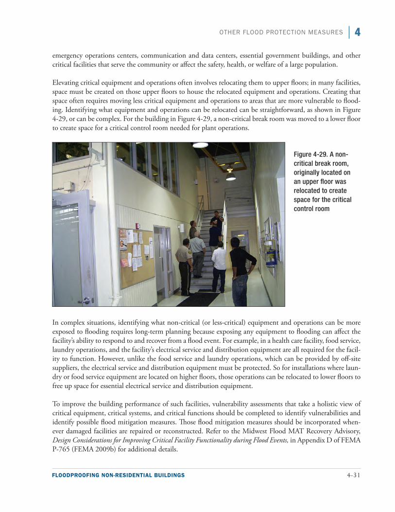
FLOODPROOFING NON-RESIDENTIAL BUILDINGS 4-31
4OTHER FLOOD PROTECTION MEASURES
emergency operations centers, communication and data centers, essential government buildings, and other critical facilities that serve the community or affect the safety, health, or welfare of a large population.
Elevating critical equipment and operations often involves relocating them to upper floors; in many facilities, space must be created on those upper floors to house the relocated equipment and operations. Creating that space often requires moving less critical equipment and operations to areas that are more vulnerable to flood-ing. Identifying what equipment and operations can be relocated can be straightforward, as shown in Figure 4-29, or can be complex. For the building in Figure 4-29, a non-critical break room was moved to a lower floor to create space for a critical control room needed for plant operations.
In complex situations, identifying what non-critical (or less-critical) equipment and operations can be more exposed to flooding requires long-term planning because exposing any equipment to flooding can affect the facility’s ability to respond to and recover from a flood event. For example, in a health care facility, food service, laundry operations, and the facility’s electrical service and distribution equipment are all required for the facil-ity to function. However, unlike the food service and laundry operations, which can be provided by off-site suppliers, the electrical service and distribution equipment must be protected. So for installations where laun-dry or food service equipment are located on higher floors, those operations can be relocated to lower floors to free up space for essential electrical service and distribution equipment.
To improve the building performance of such facilities, vulnerability assessments that take a holistic view of critical equipment, critical systems, and critical functions should be completed to identify vulnerabilities and identify possible flood mitigation measures. Those flood mitigation measures should be incorporated when-ever damaged facilities are repaired or reconstructed. Refer to the Midwest Flood MAT Recovery Advisory, Design Considerations for Improving Critical Facility Functionality during Flood Events, in Appendix D of FEMA P-765 (FEMA 2009b) for additional details.
Figure 4-29. A non-critical break room, originally located on an upper floor was relocated to create space for the critical control room
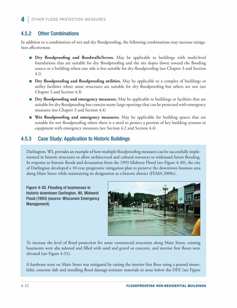
4-32 FLOODPROOFING NON-RESIDENTIAL BUILDINGS
4 OTHER FLOOD PROTECTION MEASURES
4.5.2 Other Combinations
In addition to a combination of wet and dry floodproofing, the following combinations may increase mitiga-tion effectiveness:
■■ Dry floodproofing and floodwalls/levees. May be applicable to buildings with multi-level foundations that are suitable for dry floodproofing and the site slopes down toward the flooding source or a building where one side is less suitable for dry floodproofing (see Chapter 3 and Section 4.1)
■■ Dry floodproofing and floodproofing utilities. May be applicable to a complex of buildings or utility facilities where some structures are suitable for dry floodproofing but others are not (see Chapter 3 and Section 4.3)
■■ Dry floodproofing and emergency measures. May be applicable to buildings or facilities that are suitable for dry floodproofing but contain many large openings that can be protected with emergency measures (see Chapter 3 and Section 4.4)
■■ Wet floodproofing and emergency measures. May be applicable for building spaces that are suitable for wet floodproofing where there is a need to protect a portion of key building systems or equipment with emergency measures (see Section 4.2 and Section 4.4)
4.5.3 Case Study: Application to Historic Buildings
Darlington, WI, provides an example of how multiple floodproofing measures can be successfully imple-mented in historic structures to allow architectural and cultural resources to withstand future flooding. In response to historic floods and devastation from the 1993 Midwest Flood (see Figure 4-30), the city of Darlington developed a 10-year progressive mitigation plan to preserve the downtown business area along Main Street while maintaining its designation as a historic district (FEMA 2008c).
To increase the level of flood protection for some commercial structures along Main Street, existing basements were aba ndoned and filled with sand and gravel or concrete, and interior first floors were elevated (see Figure 4-31).
A hardware store on Main Street was mitigated by raising the interior first floor using a poured mono-lithic concrete slab and installing flood damage-resistant materials in areas below the DFE (see Figure
Figure 4-30. Flooding of businesses in historic downtown Darlington, WI, Midwest Flood (1993) (source: Wisconsin Emergency Management)
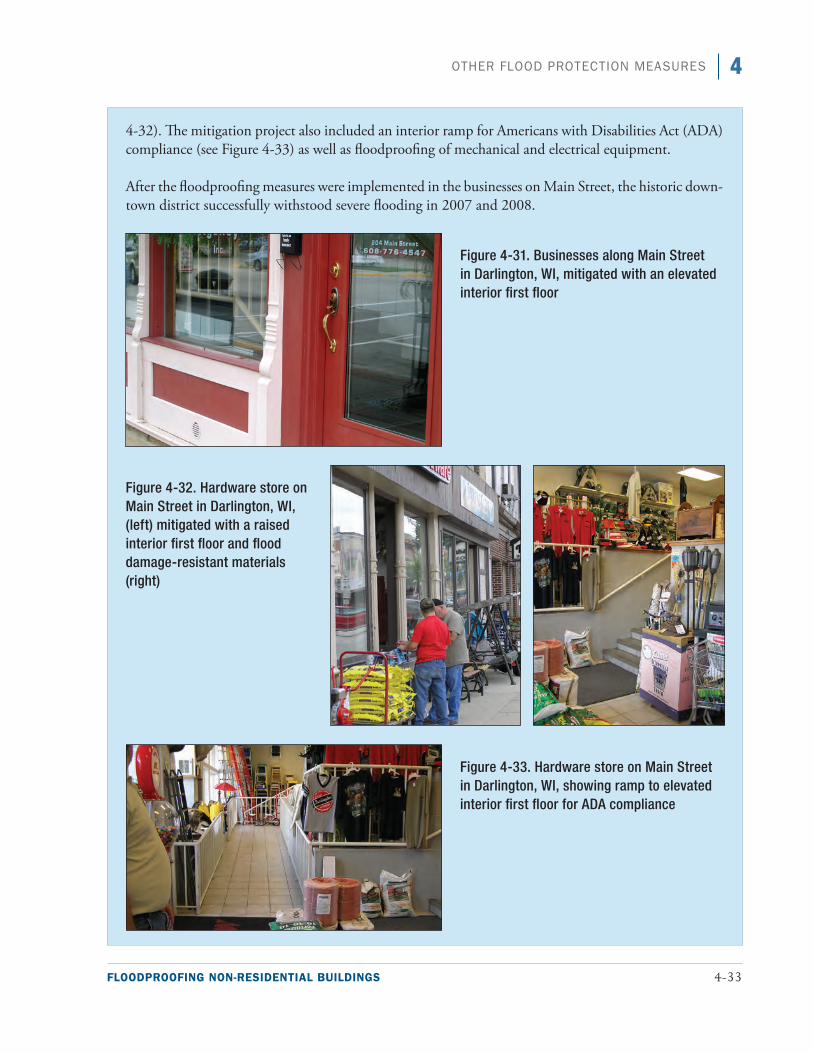
FLOODPROOFING NON-RESIDENTIAL BUILDINGS 4-33
4OTHER FLOOD PROTECTION MEASURES
4-32). The mitigation project also included an interior ramp for Americans with Disabilities Act (ADA) compliance (see Figure 4-33) as well as floodproofing of mechanical and electrical equipment.
After the floodproofing measures were implemented in the businesses on Main Street, the historic down-town district successfully withstood severe flooding in 2007 and 2008.
Figure 4-31. Businesses along Main Street in Darlington, WI, mitigated with an elevated interior first floor
Figure 4-32. Hardware store on Main Street in Darlington, WI, (left) mitigated with a raised interior first floor and flood damage-resistant materials (right)
Figure 4-33. Hardware store on Main Street in Darlington, WI, showing ramp to elevated interior first floor for ADA compliance

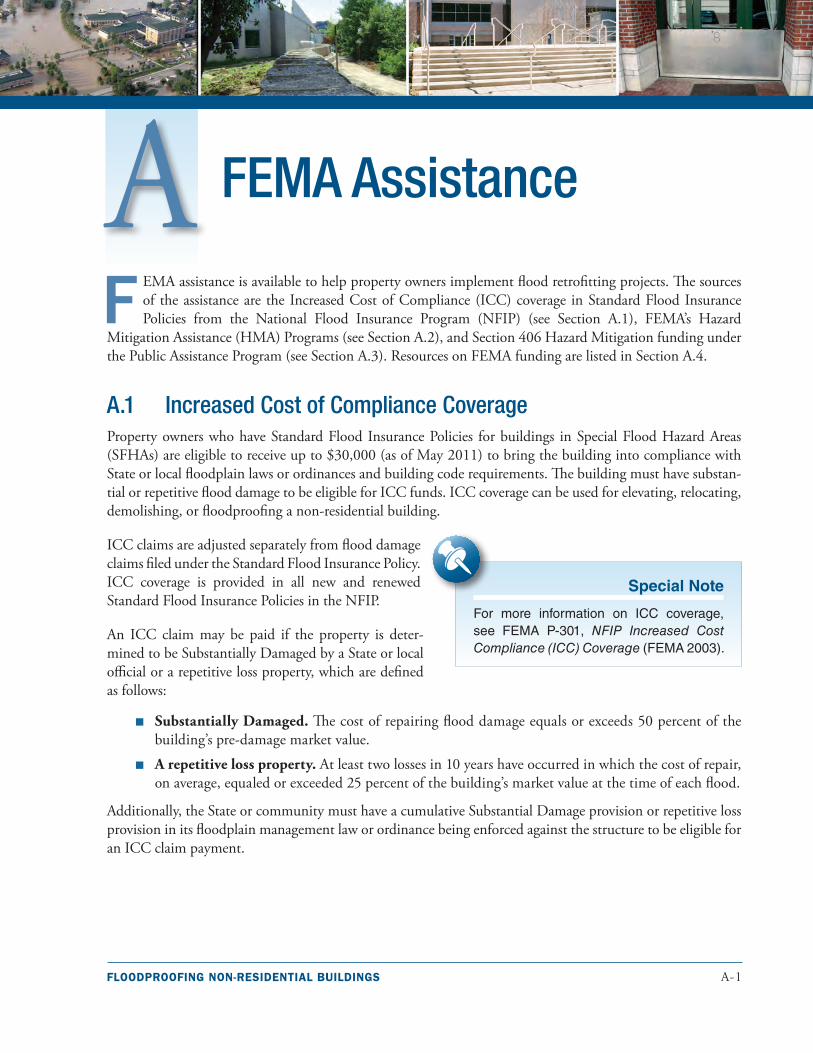
FLOODPROOFING NON-RESIDENTIAL BUILDINGS A-1
F EMA assistance is available to help property owners implement flood retrofitting projects. The sources of the assistance are the Increased Cost of Compliance (ICC) coverage in Standard Flood Insurance Policies from the National Flood Insurance Program (NFIP) (see Section A.1), FEMA’s Hazard
Mitigation Assistance (HMA) Programs (see Section A.2), and Section 406 Hazard Mitigation funding under the Public Assistance Program (see Section A.3). Resources on FEMA funding are listed in Section A.4.
A.1 Increased Cost of Compliance CoverageProperty owners who have Standard Flood Insurance Policies for buildings in Special Flood Hazard Areas (SFHAs) are eligible to receive up to $30,000 (as of May 2011) to bring the building into compliance with State or local floodplain laws or ordinances and building code requirements. The building must have substan-tial or repetitive flood damage to be eligible for ICC funds. ICC coverage can be used for elevating, relocating, demolishing, or floodproofing a non-residential building.
ICC claims are adjusted separately from flood damage claims filed under the Standard Flood Insurance Policy. ICC coverage is provided in all new and renewed Standard Flood Insurance Policies in the NFIP.
An ICC claim may be paid if the property is deter-mined to be Substantially Damaged by a State or local official or a repetitive loss property, which are defined as follows:
■■ Substantially Damaged. The cost of repairing flood damage equals or exceeds 50 percent of the building’s pre-damage market value.
■■ A repetitive loss property. At least two losses in 10 years have occurred in which the cost of repair, on average, equaled or exceeded 25 percent of the building’s market value at the time of each flood.
Additionally, the State or community must have a cumulative Substantial Damage provision or repetitive loss provision in its floodplain management law or ordinance being enforced against the structure to be eligible for an ICC claim payment.
FEMA Assistance
Special Note
For more information on ICC coverage, see FEMA P-301, NFIP Increased Cost Compliance (ICC) Coverage (FEMA 2003).
A-2 FLOODPROOFING NON-RESIDENTIAL BUILDINGS
A FEMA ASSISTANCE
A.2 FEMA’s Hazard Mitigation Assistance ProgramsFEMA’s HMA Programs present a critical opportunity to reduce the risk to individuals and property from natural hazards while simultaneously reducing reliance on Federal disaster funds. The programs are authorized by Section 404 of the Robert T. Stafford Disaster Relief and Emergency Assistance Act of 1988, as amended (Title 42, United States Code [U.S.C.] 5170c), Section 203 of the Stafford Act, 42 U.S.C. 5133 and Section 1366 of the National Flood Insurance Act of 1968, as amended (42 U.S.C. 4104c). All programs are subject to changes in statutory requirements and amounts of authorized assistance.
All mitigation projects must be cost-effective, cost reasonable and technically feasible and meet Environmental Planning and Historic Preservation requirements in accordance with HMA Program requirements. States, territories, federally recognized Indian tribal governments, and communities are eli-gible and encouraged to take advantage of funding provided by the following HMA Programs in both the pre- and post-disaster time frames:
■■ Hazard Mitigation Grant Program (HMGP). Provides grants for long-term hazard mitigation measures after a major disaster declaration in a given State. The purpose of HMGP is to reduce the loss of life and property as a result of natural disasters and to enable the implementation of mitigation measures during the recovery from a disaster.
■■ Pre-Disaster Mitigation (PDM) Program. Provides nationally competitive grants for hazard mitigation planning and implementing mitigation projects before a disaster event. Funding the plans and projects reduces the risk to people and property and the reliance on funding that is authorized after a Presidential disaster declaration to rebuild.
■■ Flood Mitigation Assistance (FMA) Program. Provides grants for certain flood mitigation projects to reduce or eliminate flood risk to buildings, manufactured homes, and other buildings that are currently NFIP insured. The National Flood Insurance Fund (NFIF) provides the funding for the FMA program.
HMGP is available, when authorized under a Presidential major disaster declaration, in the areas of the State requested by the Governor. The PDM and FMA programs are subject to the availability of appropriation fund-ing, as well as any program-specific directive or restriction made with respect to such funds.
Table A-1 is a summary of the flood mitigation projects in non-residential buildings that are eligible for fund-ing under HMA Programs.
Special Note
For more information on FEMA Hazard Mitigation Assistance programs, see https://www.fema.gov/hazard-mitigation-assistance.
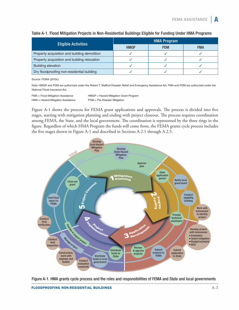
FLOODPROOFING NON-RESIDENTIAL BUILDINGS A-3
AFEMA ASSISTANCE
Table A-1. Flood Mitigation Projects in Non-Residential Buildings Eligible for Funding Under HMA Programs
Eligible ActivitiesHMA Program
HMGP PDM FMA
Property acquisition and building demolition 3■ 3 3
Property acquisition and building relocation 3 3■ 3■
Building elevation 3■ 3■ 3■
Dry floodproofing non-residential building 3 3■ 3■
Source: FEMA (2010c)
Note: HMGP and PDM are authorized under the Robert T. Stafford Disaster Relief and Emergency Assistance Act. FMA and PDM are authorized under the
National Flood Insurance Act.
FMA = Flood Mitigation Assistance HMGP = Hazard Mitigation Grant Program
HMA = Hazard Mitigation Assistance PDM = Pre-Disaster Mitigation
Figure A-1 shows the process for FEMA grant applications and approvals. The process is divided into five stages, starting with mitigation planning and ending with project closeout. The process requires coordination among FEMA, the State, and the local government. The coordination is represented by the three rings in the figure. Regardless of which HMA Program the funds will come from, the FEMA grants cycle process includes the five stages shown in Figure A-1 and described in Sections A.2.1 through A.2.5.
Figure A-1. HMA grants cycle process and the roles and responsibilities of FEMA and State and local governments

A-4 FLOODPROOFING NON-RESIDENTIAL BUILDINGS
A FEMA ASSISTANCE
A.2.1 Stage 1: Mitigation Planning
All project grant applications require a State or tribal multi-hazard mitigation plan. The plan must describe the process for identifying the hazard risks in a community and the actions that will help reduce the risks. Non-residential flood mitigation projects that are proposed for FEMA funding under HMA Programs must be consistent with the State’s or tribe’s mitigation plan. The mitigation planning process requires public par-ticipation and the identification of measures to reduce risks and is therefore a good opportunity for property owners to address concerns about flood hazards. More information is available at http://www.fema.gov/hazard-mitigation-planning-overview.
A.2.2 Stage 2: Program Funding
HMA Programs enable hazard mitigation measures to be implemented before, during, and after disasters. Funding depends on the availability of appropriation funding or is based on disaster recovery expenditures, as well as any directive or restriction made with respect to such funds. HMGP funding depends on Federal assistance provided for disaster recovery following a Presidential disaster declaration in a State, and PDM and FMA funding may be authorized annually by Congress.
When the application period opens, the State notifies local governments of the availability of funds and relays information about the application process, project requirements, and eligibility criteria for the local govern-ment. Table A-2 shows the cost-share requirements for the HMA Programs. Property owners should work with their local governments to express interest in participating in a flood mitigation project; the local government can then submit a subapplication to the State and request HMA funding. In general, the community applying for the grant must participate in the NFIP. Eligible subapplicants include State agencies, Indian tribal govern-ments, local governments and communities, and private non-profit organizations.
Table A-3 lists the eligibility of subapplicants for HMA Program grant funding.
Table A-2. Cost-Share Requirements for the HMA Program Grants
HMA Program Subcategory Federal/Non-Federal Share(a)
HMGP All subapplicants 75/25
PDM
All subapplicants 75/25
Subgrantee is small impoverished community 90/10
Tribal Grantee is small impoverished community 90/10
FMA All subapplicants Up to 100/0 for certain properties
(a) Ratios are as of February 2010. Refer to the current fiscal year’s HMA Unified Guidance for current ratios when referencing this table. The current version of the HMA Unified Guidance is available at http://www.fema.gov/hazard-mitigation-assistance.
FMA = Flood Mitigation Assistance HMGP = Hazard Mitigation Grant Program HMA = Hazard Mitigation Assistance PDM = Pre-Disaster Mitigation
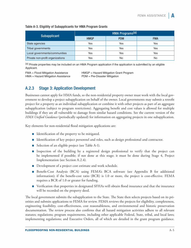
FLOODPROOFING NON-RESIDENTIAL BUILDINGS A-5
AFEMA ASSISTANCE
Table A-3. Eligiility of Subapplicants for HMA Program Grants
SubapplicantHMA Programs(a)
HMGP PDM FMA
State agencies Yes Yes Yes
Tribal governments Yes Yes Yes
Local governments/communities Yes Yes Yes
Private non-profit organizations Yes No No
(a) Private properties may be included on an HMA Program application if the application is submitted by an eligible Applicant.
FMA = Flood Mitigation Assistance HMGP = Hazard Mitigation Grant Program HMA = Hazard Mitigation Assistance PDM = Pre-Disaster Mitigation
A.2.3 Stage 3: Application Development
Businesses cannot apply for HMA funds, so the non-residential property owner must work with the local gov-ernment to develop a project subapplication on behalf of the owner. Local governments may submit a retrofit project for a property as an individual subapplication or combine it with other projects as part of an aggregate subapplication (subject to program restrictions). Aggregating benefit and cost values is allowed for multiple buildings if they are all vulnerable to damage from similar hazard conditions. See the current version of the HMA Unified Guidance (periodically updated) for information on aggregating projects in one subapplication.
Key elements for non-residential flood mitigation applications are:
■■ Identification of the property to be mitigated.
■■ Identification of key project personnel and roles, such as design professional and contractor.
■■ Selection of an eligible project (see Table A-1).
■■ Inspection of the building by a registered design professional to verify that the project can be implemented if possible; if not done at this stage; it must be done during Stage 4, Project Implementation (see Section A.2.4).
■■ Development of a project cost estimate and work schedule.
■■ Benefit-Cost Analysis (BCA) using FEMA’s BCA software (see Appendix B for additional information); if the benefit-cost ratio (BCR) is 1.0 or more, the project is cost-effective. FEMA requires a BCR of 1.0 or greater for funding.
■■ Verification that properties in designated SFHAs will obtain flood insurance and that the insurance will be recorded on the property deed.
The local government submits the subapplication to the State. The State then selects projects based on its pri-orities and submits applications to FEMA for review. FEMA reviews the projects for eligibility, completeness, engineering feasibility, cost-effectiveness, cost reasonableness, and environmental and historic preservation documentation. The review process also confirms that all hazard mitigation activities adhere to all relevant statutes; regulations; program requirements, including other applicable Federal, State, tribal, and local laws; implementing regulations; and Executive Orders, all of which are detailed in the grant program guidance.
A-6 FLOODPROOFING NON-RESIDENTIAL BUILDINGS
A FEMA ASSISTANCE
The most current version of the guidance can be found at the FEMA HMA website (http://www.fema.gov/hazard-mitigation-assistance).
Once FEMA approves a project and awards the grant, the State distributes the funds to the local government, which distributes it to individuals as appropriate. No construction activities should begin until after the money has been awarded because HMA funding is not available for activities initiated or completed prior to award or final approval.
A.2.4 Stage 4: Project Implementation
After the State has awarded the funds to the local government, the next stage is project implementation. HMA projects must be completed within a specified period of time (the period of performance), which is normally not more than 36 months. During the period of performance, the local government must maintain a record of work and expenditures for the quarterly reports that the State submits to FEMA.
Because the final design may not be completed prior to award, once the project is awarded, the design must be finalized by a registered design professional with some exceptions. If the scope of work or cost estimate changes as a result of completing the final design, the HMA Unified Guidance should be consulted for direction on scope of work modifications. If there is already a final design when the grant is awarded, the subgrantee can proceed with the appropriate contracting procurement procedures to secure the services of a contractor to exe-cute the requirements in the design and grant documents.
Some grant projects do not require the services of a design professional. In these circumstances, once the grant is awarded, the subgrantee can proceed with appropriate contracting procurement procedures to secure the services of a contractor to execute the requirements in the contract documents necessary to perform the work in the approved grant.
To summarize, the basic steps in implementing an approved HMA mitigation flood retrofit grant project are:
1. If a design was not developed before Stage 3, secure a registered design professional to design, inspect, and sign off on a mitigation retrofit solution within the bounds of the approved grant.
2. If a design solution was developed before Stage 3 or if a registered design professional is not needed because of the nature of the work, secure the services of a contractor to execute the work in the approved grant.
3. Monitor the work being performed to ensure that all grant requirements are being met.
4. Inspect the finished project and verify that all grant requirements have been met. Work with the designer / contractor to resolve any issues of concern and work with the State in closing out the grant after all requirements have been met.
A.2.5 Stage 5: Project Closeout
When the grant project has been completed, a registered design professional (preferably the same one as above) should conduct a final inspection and verify in writing that the project he or she designed/signed off on was implemented as intended in the approved grant. If a contractor was the only professional who performed the
FLOODPROOFING NON-RESIDENTIAL BUILDINGS A-7
AFEMA ASSISTANCE
work, the contractor should verify in writing that he or she performed the work as outlined in the contract and the grant. It is crucial for the subgrantee to ensure that the grant requirements have been met through any contracts the subgrantee has have with design professionals or contractors because the subgrantee is ultimately responsible for meeting the grant requirements. Poorly written contracts can result in work that complies with the contract but is noncompliant with the grant requirements. The written verification of the work performed along with other project documentation demonstrating grant compliance will help facilitate a smooth, effi-cient project closeout.
After obtaining project verification from the designer/contractor, the subgrantee then submits the grant project documentation to the State. The State verifies that the work was completed in accordance with the approved grant documentation, including the grant scope of work, and performs the closeout procedures. If the prop-erty is in an SFHA, the local government must provide documentation of flood insurance for the property and a copy of the recorded deed amendment. The HMA Unified Guidance contains a description of all closeout requirements that must be addressed.
A.3 The Public Assistance Program and Section 406 Hazard Mitigation Funding
The Public Assistance (PA) Program is a grant pro-gram authorized by the Robert T. Stafford Disaster and Emergency Assistance Act (the Stafford Act) to make funding available for response and recovery efforts after the President has declared a disaster or emergency.
After the declaration is made, FEMA determines which locations are eligible for assistance under which categories of work. Eligible disaster-related work, which is either emergency or permanent work, is divided into seven categories, as listed below. The first two categories are emergency work, and the other categories are permanent work.
■■ Category A: Debris Removal (Emergency Work)
■■ Category B: Emergency Protective Measures (Emergency Work)
■■ Category C: Roads and Bridges (Permanent Work)
■■ Category D: Water Control Facilities (Permanent Work)
■■ Category E: Buildings and Equipment (Permanent Work)
■■ Category F: Utilities (Permanent Work)
■■ Category G: Parks, Recreational Facilities and Other Items (Permanent Work)
Entities that are eligible to apply for PA funding are limited to State agencies, local governments, private nonprofit organizations (which must meet stringent requirements to be determined eligible), and federally recognized Indian tribes or authorized tribal organizations and Alaskan Native village organizations.
Special Note
More information on the Stafford Act and Section 406 is available at:h t t p : / / w w w. fe m a . g ov / p u b l i c - a s s i s -tance-local-state-tribal-and-non-profit/hazard-mitigation-funding-under-sec-tion-406-0.
A-8 FLOODPROOFING NON-RESIDENTIAL BUILDINGS
A FEMA ASSISTANCE
Under the PA Program, the FEMA/State cost share is usually 75 percent/25 percent, although the cost share is subject to change based on the severity of the disaster. Applicants are reimbursed for eligible costs under the categories of work that FEMA has determined eligible for reimbursement under that specific disaster declaration.
The PA Program has a required focus on restoring damaged infrastructure to its pre-disaster function and capacity. Section 406 of the Stafford Act allows funding of mitigation measures that go beyond restoring a facility to its pre-disaster condition and is applied only to the damaged element of the facility. Mitigation measures must be cost-effective, cost reasonable, technically feasible and meet Environmental Planning and Historic Preservation requirements in accordance with Federal laws, regulations, and Executive Orders and must reduce the risk of damage from future similar events to be eligible for Section 406 funding.
Only projects involving permanent work are eligible for Section 406 hazard mitigation funding. Hazard miti-gation measures under Section 406 are considered part of the total eligible cost of the repair, restoration, reconstruction, or relocation of a facility. Funding under Section 406 is not applicable to alternate or improved projects if a new replacement facility is involved. Upgrades to meet applicable codes and standards are also not eligible under Section 406 funding because they are not mitigation measures and may be an eligible part of restoration work under the PA Program. Examples of eligible Section 406 mitigation measures are:
■■ Relocation of facilities from hazardous locations
■■ Slope stabilization to protect facilities
■■ Protection from high winds
■■ Floodproofing of buildings
■■ Flood protection of bridges and culverts
■■ Seismic protection
■■ Protection of utilities
Hazard mitigation measures submitted under Section 406 are reviewed by FEMA to ensure eligibility, techni-cal feasibility, environmental and historical compliance, and cost effectiveness. When the project has passed all reviews, FEMA obligates the funds, and the State ensures that the funds are distributed to PA Program appli-cants in accordance with State laws.
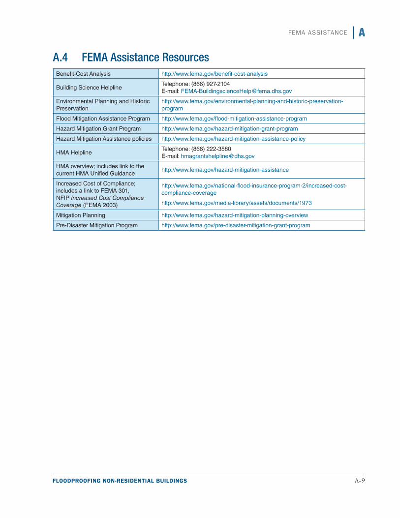
FLOODPROOFING NON-RESIDENTIAL BUILDINGS A-9
AFEMA ASSISTANCE
A.4 FEMA Assistance ResourcesBenefit-Cost Analysis http://www.fema.gov/benefit-cost-analysis
Building Science HelplineTelephone: (866) 927-2104 E-mail: [email protected]
Environmental Planning and Historic Preservation
http://www.fema.gov/environmental-planning-and-historic-preservation-program
Flood Mitigation Assistance Program http://www.fema.gov/flood-mitigation-assistance-program
Hazard Mitigation Grant Program http://www.fema.gov/hazard-mitigation-grant-program
Hazard Mitigation Assistance policies http://www.fema.gov/hazard-mitigation-assistance-policy
HMA HelplineTelephone: (866) 222-3580 E-mail: [email protected]
HMA overview; includes link to the current HMA Unified Guidance
http://www.fema.gov/hazard-mitigation-assistance
Increased Cost of Compliance; includes a link to FEMA 301, NFIP Increased Cost Compliance Coverage (FEMA 2003)
http://www.fema.gov/national-flood-insurance-program-2/increased-cost-compliance-coverage
http://www.fema.gov/media-library/assets/documents/1973
Mitigation Planning http://www.fema.gov/hazard-mitigation-planning-overview
Pre-Disaster Mitigation Program http://www.fema.gov/pre-disaster-mitigation-grant-program

Understanding the FEMA Benefit-Cost Process
T he purpose of this appendix is to provide basic guidance on using the Federal Emergency Management Agency’s (FEMA’s) Benefit-Cost
Analysis (BCA) Tool (Version 4.5.5 [FEMA 2009a]) to complete a BCA when considering floodproofing a non-residential building.
The FEMA BCA Tool is used to determine the cost effectiveness of proposed mitigation projects submit-ted for assistance under FEMA’s Hazard Mitigation Assistance grant programs. The software is used to estimate the economic consequences of a natural disaster (flood, hurricane, tornado, earthquake, or wildfire) with and without the proposed mitigation.
For flood events, loss is estimated using depth-damage functions (DDFs), which are used to predict inundation impacts to the building, contents, and use of the building. DDFs relate flood depths to predicted percentages of damage to a building exposed to inundation at a given recurrence interval. The estimated avoided damage (loss) from the mitigation project is the benefit.
The flood recurrence interval is typically based on flood hazard data from a FEMA Flood Insurance Study (FIS) and/or hydrologic and hydraulic (H&H) study. When available flood hazard data are limited, the recur-rence interval may be provided based on data collected after an event to determine the recurrence interval or by use of the unknown frequency calculator built into the Damage Frequency Assessment (DFA) module in the FEMA BCA Tool.
Anticipated damage to non-residential buildings varies based on the type of building, building attributes, and in some instances, location.
Determining the cost effectiveness of a floodproofing project can be done using either the Flood module or DFA module, both of which are part of the BCA Tool. The Flood module relies on flood hazard data, building characteristics, and DDFs, and the DFA module relies on historical or expected damage along with a recur-rence interval associated with the damage. The DFA module is used more often for floodproofing because it generally requires less data collection and may better represent the complexity of some floodproofing projects.
The data needed for the BCA Tool Flood module and BCA Tool DFA module are listed in Table B-1.
FLOODPROOFING NON-RESIDENTIAL BUILDINGS B-1
Special Note
Property owners considering a floodproof-ing retrofit may use the BCA Tool during their decision-making process. A BCA is required only when applying for FEMA miti-gation grant assistance.
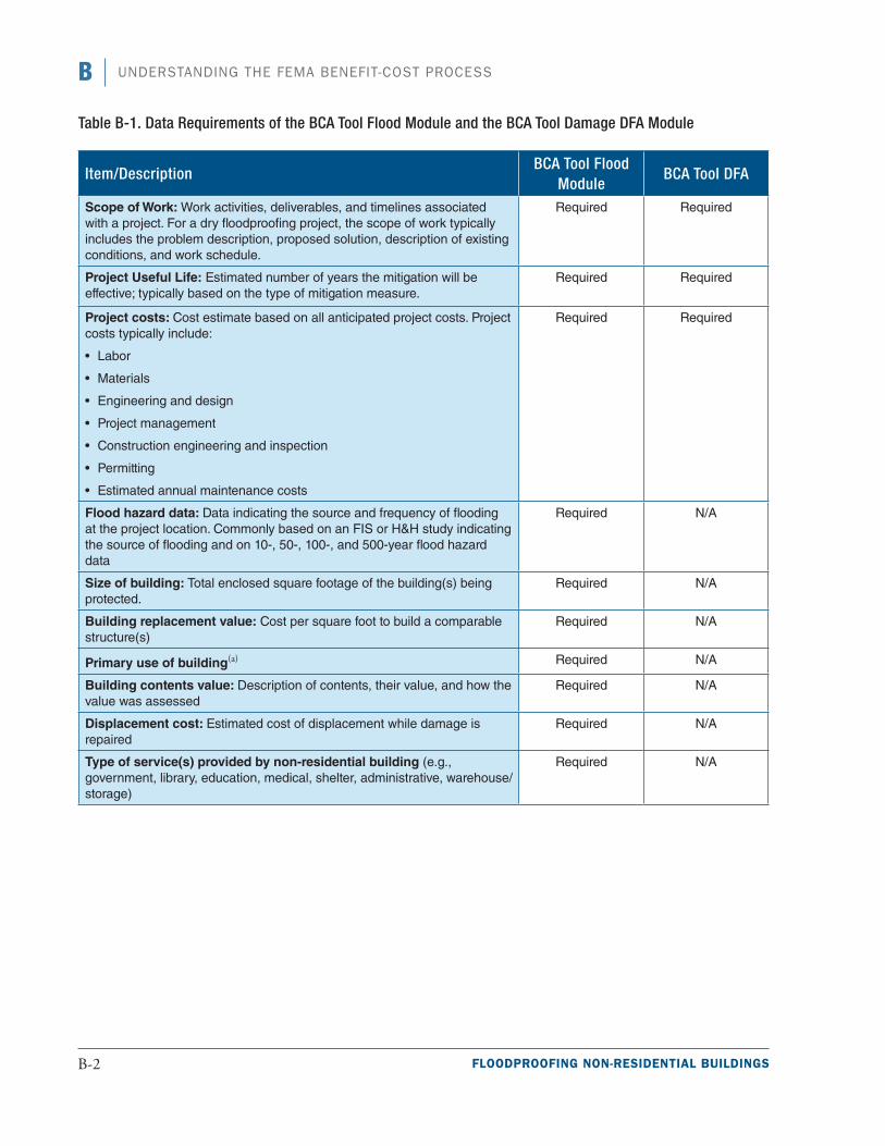
B UNDERSTANDING THE FEMA BENEFIT-COST PROCESS
Table B-1. Data Requirements of the BCA Tool Flood Module and the BCA Tool Damage DFA Module
Item/DescriptionBCA Tool Flood
ModuleBCA Tool DFA
Scope of Work: Work activities, deliverables, and timelines associated with a project. For a dry floodproofing project, the scope of work typically includes the problem description, proposed solution, description of existing conditions, and work schedule.
Required Required
Project Useful Life: Estimated number of years the mitigation will be effective; typically based on the type of mitigation measure.
Required Required
Project costs: Cost estimate based on all anticipated project costs. Project costs typically include:
• Labor
• Materials
• Engineering and design
• Project management
• Construction engineering and inspection
• Permitting
• Estimated annual maintenance costs
Required Required
Flood hazard data: Data indicating the source and frequency of flooding at the project location. Commonly based on an FIS or H&H study indicating the source of flooding and on 10-, 50-, 100-, and 500-year flood hazard data
Required N/A
Size of building: Total enclosed square footage of the building(s) being protected.
Required N/A
Building replacement value: Cost per square foot to build a comparable structure(s)
Required N/A
Primary use of building(a) Required N/A
Building contents value: Description of contents, their value, and how the value was assessed
Required N/A
Displacement cost: Estimated cost of displacement while damage is repaired
Required N/A
Type of service(s) provided by non-residential building (e.g., government, library, education, medical, shelter, administrative, warehouse/storage)
Required N/A
B-2 FLOODPROOFING NON-RESIDENTIAL BUILDINGS
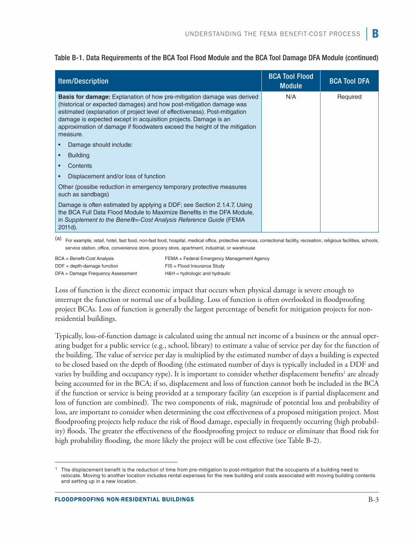
BUNDERSTANDING THE FEMA BENEFIT-COST PROCESS
Item/DescriptionBCA Tool Flood
ModuleBCA Tool DFA
Basis for damage: Explanation of how pre-mitigation damage was derived (historical or expected damages) and how post-mitigation damage was estimated (explanation of project level of effectiveness). Post-mitigation damage is expected except in acquisition projects. Damage is an approximation of damage if floodwaters exceed the height of the mitigation measure.
•• Damage should include:
•• Building
•• Contents
•• Displacement and/or loss of function
Other (possibe reduction in emergency temporary protective measures such as sandbags)
Damage is often estimated by applying a DDF; see Section 2.1.4.7, Using the BCA Full Data Flood Module to Maximize Benefits in the DFA Module, in Supplement to the Benefit=-Cost Analysis Reference Guide (FEMA 2011d).
N/A Required
(a) For example, retail, hotel, fast food, non-fast food, hospital, medical office, protective services, correctional facility, recreation, religious facilities, schools,
service station, office, convenience store, grocery store, apartment, industrial, or warehouse
BCA = Benefit-Cost Analysis FEMA = Federal Emergency Management Agency
DDF = depth-damage function FIS = Flood Insurance Study
DFA = Damage Frequency Assessment H&H = hydrologic and hydraulic
Loss of function is the direct economic impact that occurs when physical damage is severe enough to interrupt the function or normal use of a building. Loss of function is often overlooked in floodproofing project BCAs. Loss of function is generally the largest percentage of benefit for mitigation projects for non-residential buildings.
Typically, loss-of-function damage is calculated using the annual net income of a business or the annual oper-ating budget for a public service (e.g., school, library) to estimate a value of service per day for the function of the building. The value of service per day is multiplied by the estimated number of days a building is expected to be closed based on the depth of flooding (the estimated number of days is typically included in a DDF and varies by building and occupancy type). It is important to consider whether displacement benefits1 are already being accounted for in the BCA; if so, displacement and loss of function cannot both be included in the BCA if the function or service is being provided at a temporary facility (an exception is if partial displacement and loss of function are combined). The two components of risk, magnitude of potential loss and probability of loss, are important to consider when determining the cost effectiveness of a proposed mitigation project. Most floodproofing projects help reduce the risk of flood damage, especially in frequently occurring (high probabil-ity) floods. The greater the effectiveness of the floodproofing project to reduce or eliminate that flood risk for high probability flooding, the more likely the project will be cost effective (see Table B-2).
1 The displacement benefit is the reduction of time from pre-mitigation to post-mitigation that the occupants of a building need to relocate. Moving to another location includes rental expenses for the new building and costs associated with moving building contents and setting up in a new location.
Table B-1. Data Requirements of the BCA Tool Flood Module and the BCA Tool Damage DFA Module (continued)
FLOODPROOFING NON-RESIDENTIAL BUILDINGS B-3

B UNDERSTANDING THE FEMA BENEFIT-COST PROCESS
Table B-2. Likelihood of Cost Effectiveness of Floodproofing Project
Magnitude of Potential Loss ($)
Probability of Loss
Low Medium HighLow Unlikely Unlikely Likely
Medium Unlikely Likely Highly Likely
High Likely Likely Highly Likely
B-4 FLOODPROOFING NON-RESIDENTIAL BUILDINGS
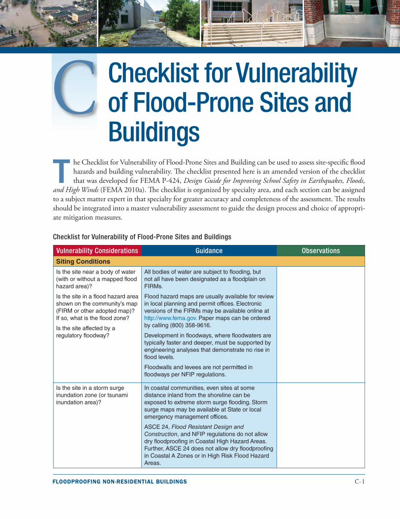
FLOODPROOFING NON-RESIDENTIAL BUILDINGS C-1
Checklist for Vulnerability of Flood-Prone Sites and Buildings
T he Checklist for Vulnerability of Flood-Prone Sites and Building can be used to assess site-specific flood hazards and building vulnerability. The checklist presented here is an amended version of the checklist that was developed for FEMA P-424, Design Guide for Improving School Safety in Earthquakes, Floods,
and High Winds (FEMA 2010a). The checklist is organized by specialty area, and each section can be assigned to a subject matter expert in that specialty for greater accuracy and completeness of the assessment. The results should be integrated into a master vulnerability assessment to guide the design process and choice of appropri-ate mitigation measures.
Checklist for Vulnerability of Flood-Prone Sites and Buildings
Vulnerability Considerations Guidance Observations
Siting Conditions
Is the site near a body of water (with or without a mapped flood hazard area)?
Is the site in a flood hazard area shown on the community’s map (FIRM or other adopted map)? If so, what is the flood zone?
Is the site affected by a regulatory floodway?
All bodies of water are subject to flooding, but not all have been designated as a floodplain on FIRMs.
Flood hazard maps are usually available for review in local planning and permit offices. Electronic versions of the FIRMs may be available online at http://www.fema.gov. Paper maps can be ordered by calling (800) 358-9616.
Development in floodways, where floodwaters are typically faster and deeper, must be supported by engineering analyses that demonstrate no rise in flood levels.
Floodwalls and levees are not permitted in floodways per NFIP regulations.
Is the site in a storm surge inundation zone (or tsunami inundation area)?
In coastal communities, even sites at some distance inland from the shoreline can be exposed to extreme storm surge flooding. Storm surge maps may be available at State or local emergency management offices.
ASCE 24, Flood Resistant Design and Construction, and NFIP regulations do not allow dry floodproofing in Coastal High Hazard Areas. Further, ASCE 24 does not allow dry floodproofing in Coastal A Zones or in High Risk Flood Hazard Areas.
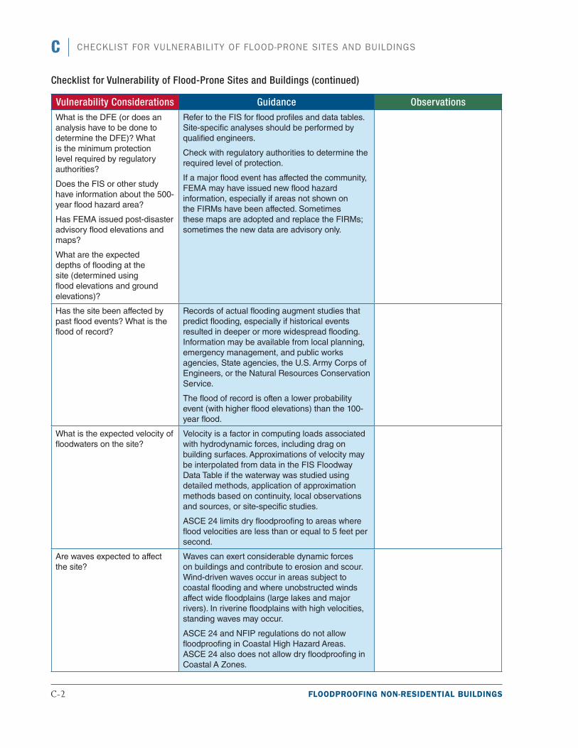
C-2 FLOODPROOFING NON-RESIDENTIAL BUILDINGS
C CHECKLIST FOR VULNERABILITY OF FLOOD-PRONE SITES AND BUILDINGS
Vulnerability Considerations Guidance ObservationsWhat is the DFE (or does an analysis have to be done to determine the DFE)? What is the minimum protection level required by regulatory authorities?
Does the FIS or other study have information about the 500-year flood hazard area?
Has FEMA issued post-disaster advisory flood elevations and maps?
What are the expected depths of flooding at the site (determined using flood elevations and ground elevations)?
Refer to the FIS for flood profiles and data tables. Site-specific analyses should be performed by qualified engineers.
Check with regulatory authorities to determine the required level of protection.
If a major flood event has affected the community, FEMA may have issued new flood hazard information, especially if areas not shown on the FIRMs have been affected. Sometimes these maps are adopted and replace the FIRMs; sometimes the new data are advisory only.
Has the site been affected by past flood events? What is the flood of record?
Records of actual flooding augment studies that predict flooding, especially if historical events resulted in deeper or more widespread flooding. Information may be available from local planning, emergency management, and public works agencies, State agencies, the U.S. Army Corps of Engineers, or the Natural Resources Conservation Service.
The flood of record is often a lower probability event (with higher flood elevations) than the 100-year flood.
What is the expected velocity of floodwaters on the site?
Velocity is a factor in computing loads associated with hydrodynamic forces, including drag on building surfaces. Approximations of velocity may be interpolated from data in the FIS Floodway Data Table if the waterway was studied using detailed methods, application of approximation methods based on continuity, local observations and sources, or site-specific studies.
ASCE 24 limits dry floodproofing to areas where flood velocities are less than or equal to 5 feet per second.
Are waves expected to affect the site?
Waves can exert considerable dynamic forces on buildings and contribute to erosion and scour. Wind-driven waves occur in areas subject to coastal flooding and where unobstructed winds affect wide floodplains (large lakes and major rivers). In riverine floodplains with high velocities, standing waves may occur.
ASCE 24 and NFIP regulations do not allow floodproofing in Coastal High Hazard Areas. ASCE 24 also does not allow dry floodproofing in Coastal A Zones.
Checklist for Vulnerability of Flood-Prone Sites and Buildings (continued)
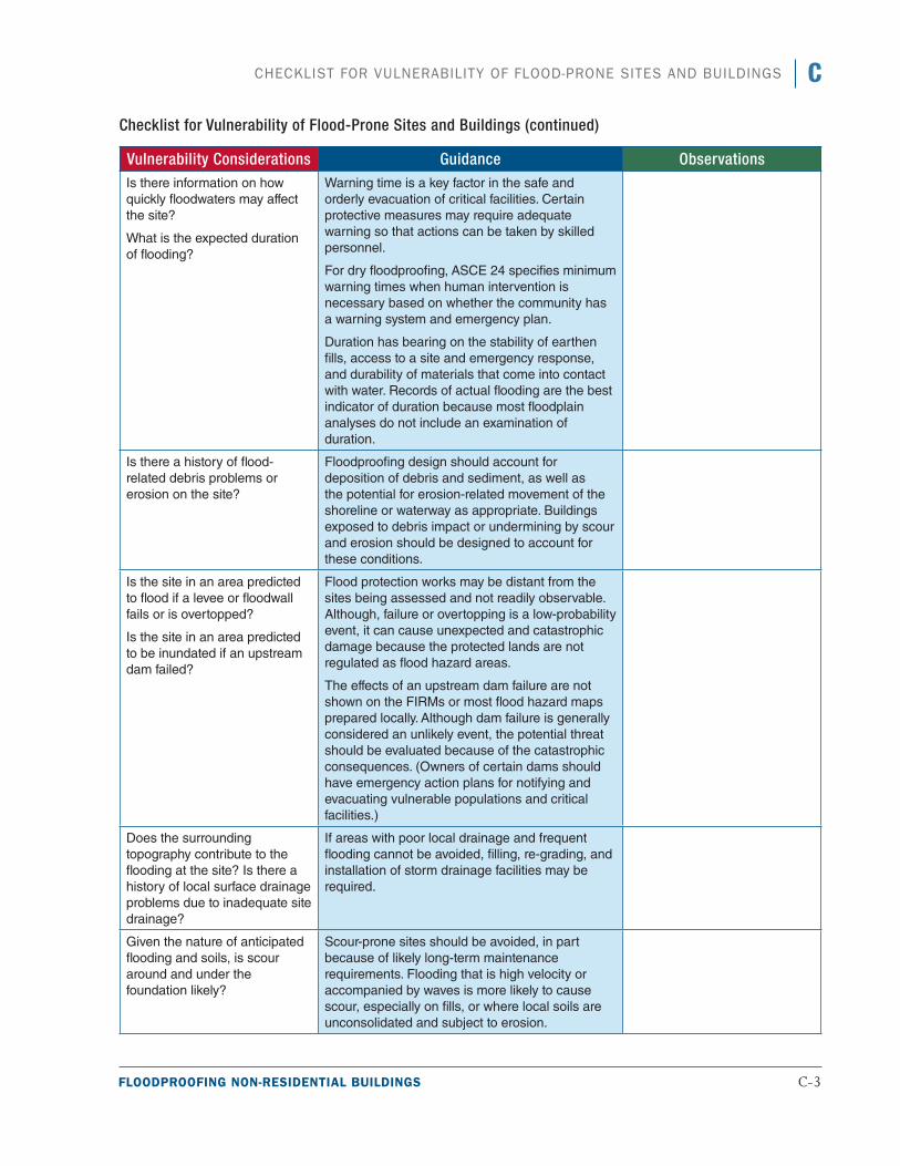
FLOODPROOFING NON-RESIDENTIAL BUILDINGS C-3
CCHECKLIST FOR VULNERABILITY OF FLOOD-PRONE SITES AND BUILDINGS
Vulnerability Considerations Guidance ObservationsIs there information on how quickly floodwaters may affect the site?
What is the expected duration of flooding?
Warning time is a key factor in the safe and orderly evacuation of critical facilities. Certain protective measures may require adequate warning so that actions can be taken by skilled personnel.
For dry floodproofing, ASCE 24 specifies minimum warning times when human intervention is necessary based on whether the community has a warning system and emergency plan.
Duration has bearing on the stability of earthen fills, access to a site and emergency response, and durability of materials that come into contact with water. Records of actual flooding are the best indicator of duration because most floodplain analyses do not include an examination of duration.
Is there a history of flood-related debris problems or erosion on the site?
Floodproofing design should account for deposition of debris and sediment, as well as the potential for erosion-related movement of the shoreline or waterway as appropriate. Buildings exposed to debris impact or undermining by scour and erosion should be designed to account for these conditions.
Is the site in an area predicted to flood if a levee or floodwall fails or is overtopped?
Is the site in an area predicted to be inundated if an upstream dam failed?
Flood protection works may be distant from the sites being assessed and not readily observable. Although, failure or overtopping is a low-probability event, it can cause unexpected and catastrophic damage because the protected lands are not regulated as flood hazard areas.
The effects of an upstream dam failure are not shown on the FIRMs or most flood hazard maps prepared locally. Although dam failure is generally considered an unlikely event, the potential threat should be evaluated because of the catastrophic consequences. (Owners of certain dams should have emergency action plans for notifying and evacuating vulnerable populations and critical facilities.)
Does the surrounding topography contribute to the flooding at the site? Is there a history of local surface drainage problems due to inadequate site drainage?
If areas with poor local drainage and frequent flooding cannot be avoided, filling, re-grading, and installation of storm drainage facilities may be required.
Given the nature of anticipated flooding and soils, is scour around and under the foundation likely?
Scour-prone sites should be avoided, in part because of likely long-term maintenance requirements. Flooding that is high velocity or accompanied by waves is more likely to cause scour, especially on fills, or where local soils are unconsolidated and subject to erosion.
Checklist for Vulnerability of Flood-Prone Sites and Buildings (continued)
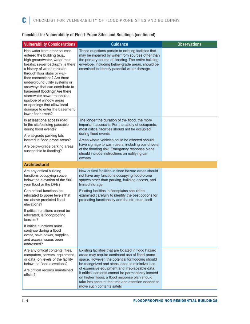
C-4 FLOODPROOFING NON-RESIDENTIAL BUILDINGS
C CHECKLIST FOR VULNERABILITY OF FLOOD-PRONE SITES AND BUILDINGS
Vulnerability Considerations Guidance ObservationsHas water from other sources entered the building (e.g., high groundwater, water main breaks, sewer backup)? Is there a history of water intrusion through floor slabs or wall-floor connections? Are there underground utility systems or areaways that can contribute to basement flooding? Are there stormwater sewer manholes upslope of window areas or openings that allow local drainage to enter the basement/lower floor areas?
These questions pertain to existing facilities that may be impaired by water from sources other than the primary source of flooding. The entire building envelope, including below-grade areas, should be examined to identify potential water damage.
Is at least one access road to the site/building passable during flood events?
Are at-grade parking lots located in flood-prone areas?
Are below-grade parking areas susceptible to flooding?
The longer the duration of the flood, the more important access is. For the safety of occupants, most critical facilities should not be occupied during flood events.
Areas where vehicles could be affected should have signage to warn users, including bus drivers, of the flooding risk. Emergency response plans should include instructions on notifying car owners.
Architectural
Are any critical building functions occupying space below the elevation of the 500-year flood or the DFE?
Can critical functions be relocated to upper levels that are above predicted flood elevations?
If critical functions cannot be relocated, is floodproofing feasible?
If critical functions must continue during a flood event, have power, supplies, and access issues been addressed?
New critical facilities in flood hazard areas should not have any functions occupying flood-prone spaces other than parking, building access, and limited storage.
Existing facilities in floodplains should be examined carefully to identify the best options for protecting functionality and the structure itself.
Are any critical contents (files, computers, servers, equipment, or data) on levels of the facility below the flood elevations?
Are critical records maintained offsite?
Existing facilities that are located in flood hazard areas may require continued use of flood-prone space. However, the potential for flooding should be recognized and steps taken to minimize loss of expensive equipment and irreplaceable data. If critical contents cannot be permanently located on higher floors, a flood response plan should take into account the time and attention needed to move such contents safely.
Checklist for Vulnerability of Flood-Prone Sites and Buildings (continued)
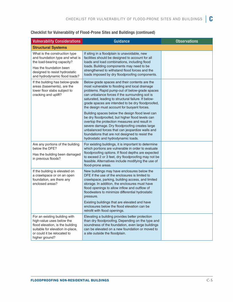
FLOODPROOFING NON-RESIDENTIAL BUILDINGS C-5
CCHECKLIST FOR VULNERABILITY OF FLOOD-PRONE SITES AND BUILDINGS
Vulnerability Considerations Guidance Observations
Structural Systems
What is the construction type and foundation type and what is the load-bearing capacity?
Has the foundation been designed to resist hydrostatic and hydrodynamic flood loads?
If siting in a floodplain is unavoidable, new facilities should be designed to account for all loads and load combinations, including flood loads. Building components may need to be strengthened to withstand flood forces and the loads imposed by dry floodproofing components.
If the building has below-grade areas (basements), are the lower floor slabs subject to cracking and uplift?
Below-grade spaces and their contents are the most vulnerable to flooding and local drainage problems. Rapid pump-out of below-grade spaces can unbalance forces if the surrounding soil is saturated, leading to structural failure. If below-grade spaces are intended to be dry floodproofed, the design must account for buoyant forces.
Building spaces below the design flood level can be dry floodproofed, but higher flood levels can overtop the protection measures and result in severe damage. Dry floodproofing creates large unbalanced forces that can jeopardize walls and foundations that are not designed to resist the hydrostatic and hydrodynamic loads.
Are any portions of the building below the DFE?
Has the building been damaged in previous floods?
For existing buildings, it is important to determine which portions are vulnerable in order to evaluate floodproofing options. If flood depths are expected to exceed 2 or 3 feet, dry floodproofing may not be feasible. Alternatives include modifying the use of flood-prone areas.
If the building is elevated on a crawlspace or on an open foundation, are there any enclosed areas?
New buildings may have enclosures below the DFE if the use of the enclosures is limited to crawlspace, parking, building access, and limited storage. In addition, the enclosures must have flood openings to allow inflow and outflow of floodwaters to minimize differential hydrostatic pressure.
Existing buildings that are elevated and have enclosures below the flood elevation can be retrofit with flood openings.
For an existing building with high-value uses below the flood elevation, is the building suitable for elevation in-place, or could it be relocated to higher ground?
Elevating a building provides better protection than dry floodproofing. Depending on the type and soundness of the foundation, even large buildings can be elevated on a new foundation or moved to a site outside the floodplain.
Checklist for Vulnerability of Flood-Prone Sites and Buildings (continued)
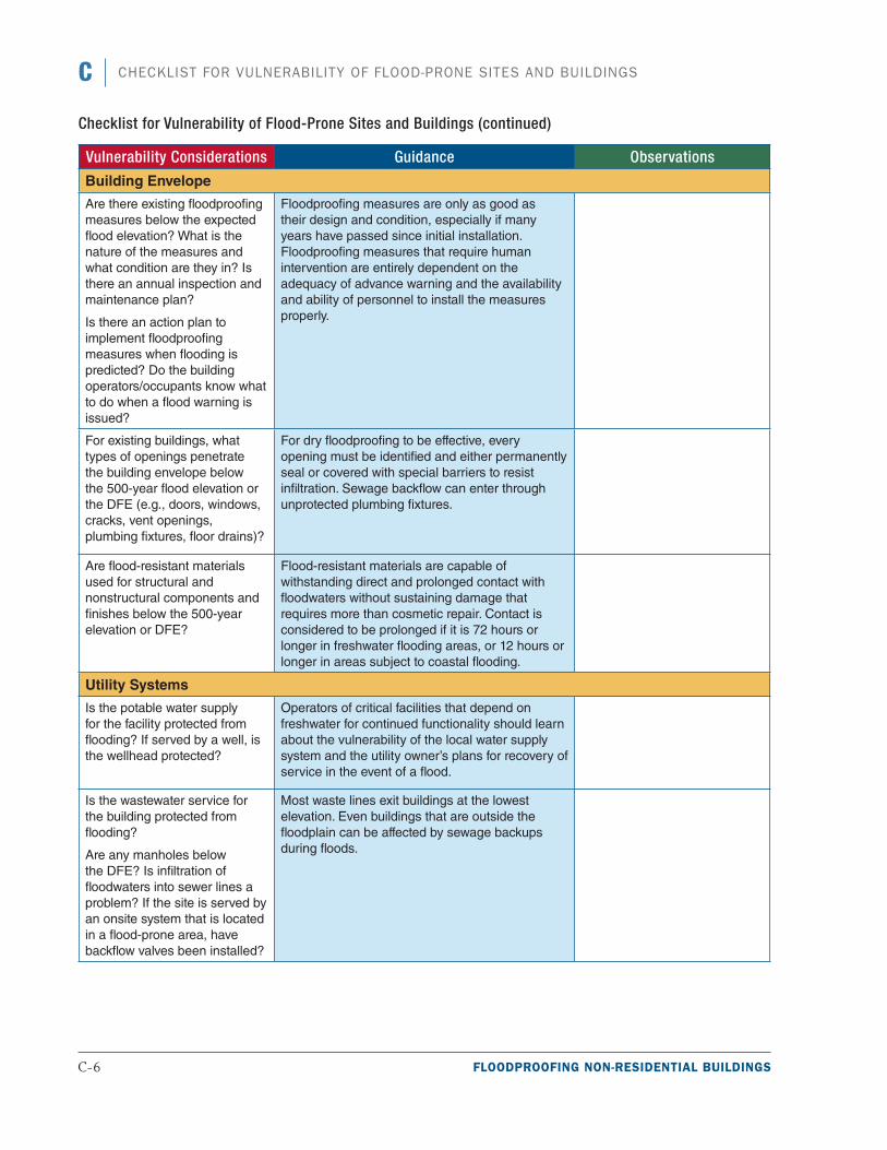
C-6 FLOODPROOFING NON-RESIDENTIAL BUILDINGS
C CHECKLIST FOR VULNERABILITY OF FLOOD-PRONE SITES AND BUILDINGS
Vulnerability Considerations Guidance Observations
Building Envelope
Are there existing floodproofing measures below the expected flood elevation? What is the nature of the measures and what condition are they in? Is there an annual inspection and maintenance plan?
Is there an action plan to implement floodproofing measures when flooding is predicted? Do the building operators/occupants know what to do when a flood warning is issued?
Floodproofing measures are only as good as their design and condition, especially if many years have passed since initial installation. Floodproofing measures that require human intervention are entirely dependent on the adequacy of advance warning and the availability and ability of personnel to install the measures properly.
For existing buildings, what types of openings penetrate the building envelope below the 500-year flood elevation or the DFE (e.g., doors, windows, cracks, vent openings, plumbing fixtures, floor drains)?
For dry floodproofing to be effective, every opening must be identified and either permanently seal or covered with special barriers to resist infiltration. Sewage backflow can enter through unprotected plumbing fixtures.
Are flood-resistant materials used for structural and nonstructural components and finishes below the 500-year elevation or DFE?
Flood-resistant materials are capable of withstanding direct and prolonged contact with floodwaters without sustaining damage that requires more than cosmetic repair. Contact is considered to be prolonged if it is 72 hours or longer in freshwater flooding areas, or 12 hours or longer in areas subject to coastal flooding.
Utility Systems
Is the potable water supply for the facility protected from flooding? If served by a well, is the wellhead protected?
Operators of critical facilities that depend on freshwater for continued functionality should learn about the vulnerability of the local water supply system and the utility owner’s plans for recovery of service in the event of a flood.
Is the wastewater service for the building protected from flooding?
Are any manholes below the DFE? Is infiltration of floodwaters into sewer lines a problem? If the site is served by an onsite system that is located in a flood-prone area, have backflow valves been installed?
Most waste lines exit buildings at the lowest elevation. Even buildings that are outside the floodplain can be affected by sewage backups during floods.
Checklist for Vulnerability of Flood-Prone Sites and Buildings (continued)
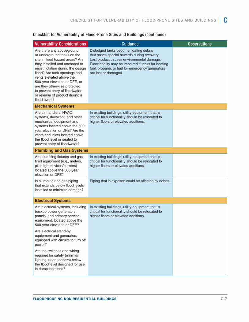
FLOODPROOFING NON-RESIDENTIAL BUILDINGS C-7
CCHECKLIST FOR VULNERABILITY OF FLOOD-PRONE SITES AND BUILDINGS
Vulnerability Considerations Guidance ObservationsAre there any aboveground or underground tanks on the site in flood hazard areas? Are they installed and anchored to resist flotation during the design flood? Are tank openings and vents elevated above the 500-year elevation or DFE, or are they otherwise protected to prevent entry of floodwater or release of product during a flood event?
Dislodged tanks become floating debris that poses special hazards during recovery. Lost product causes environmental damage. Functionality may be impaired if tanks for heating fuel, propane, or fuel for emergency generators are lost or damaged.
Mechanical Systems
Are air handlers, HVAC systems, ductwork, and other mechanical equipment and systems located above the 500-year elevation or DFE? Are the vents and inlets located above the flood level or sealed to prevent entry of floodwater?
In existing buildings, utility equipment that is critical for functionality should be relocated to higher floors or elevated additions.
Plumbing and Gas Systems
Are plumbing fixtures and gas-fired equipment (e.g., meters, pilot-light devices/burners) located above the 500-year elevation or DFE?
In existing buildings, utility equipment that is critical for functionality should be relocated to higher floors or elevated additions.
Is plumbing and gas piping that extends below flood levels installed to minimize damage?
Piping that is exposed could be affected by debris.
Electrical Systems
Are electrical systems, including backup power generators, panels, and primary service equipment, located above the 500-year elevation or DFE?
Are electrical stand-by equipment and generators equipped with circuits to turn off power?
Are the switches and wiring required for safety (minimal lighting, door openers) below the flood level designed for use in damp locations?
In existing buildings, utility equipment that is critical for functionality should be relocated to higher floors or elevated additions.
Checklist for Vulnerability of Flood-Prone Sites and Buildings (continued)

C-8 FLOODPROOFING NON-RESIDENTIAL BUILDINGS
C CHECKLIST FOR VULNERABILITY OF FLOOD-PRONE SITES AND BUILDINGS
Vulnerability Considerations Guidance Observations
Fire Alarm Systems
Is the fire alarm system located above the 500-year elevation or DFE?
In existing buildings, utility equipment that is critical for functionality should be relocated to higher floors or elevated additions.
Communications and IT Systems
Are the communication/IT systems located above the 500-year elevation or DFE?
In existing buildings, communications and IT systems critical for functionality should be relocated to higher floors or elevated additions.
ASCE American Society of Civil Engineers
DFE design flood elevation
FEMA Federal Emergency Management Agency
FIRM Flood Insurance Rate Map
HVAC heating, ventilation, and air conditioning
IT information technology
NFIP National Flood Insurance Program
Checklist for Vulnerability of Flood-Prone Sites and Buildings (continued)
FLOODPROOFING NON-RESIDENTIAL BUILDINGS D-1
References
AA (Aluminum Association). 2010. Aluminum Design Manual.
ACI (American Concrete Institute). 2008. Building Code Requirements for Structural Concrete and Commentary. ACI 318-08.
ACI/American Society of Civil Engineers (ASCE) / The Masonry Society (TMS). 2011. Building Code Requirements and Specifications for Masonry Structures. ACI 530-11/ASCE 5-11/TMS 402-11.
AISC (American Institute of Steel Construction). 2011. Steel Construction Manual (14th ed.). AISC 32511.
ANSI (American National Standards Institute) / AF&PA (American Forest & Paper Association). 2005. National Design Specification for Wood Construction. NDS-2005.
ASCE (American Society of Civil Engineers). 2005. Flood Resistant Design and Construction. ASCE Standard 24.
ASCE. 2010. Minimum Design Loads for Buildings and Other Structures. ASCE/SEI Standard 7-10.
ASTM (ASTM International). 2011. Standard Practice for Classification of Soils for Engineering Purposes (Unified Soil Classification System). ASTM D2487-11.
ASTM. 2012. Standard Test Methods for Laboratory Compaction Characteristics of Soil Using Standard Effort. ASTM D698-12.
AWPA (American Wood Protection Association). 2012. Use Category System: User Specification for Treated Wood. AWPA-U1-12.
Columbus Regional Hospital. 2012. “About Us.” Available at http://www.crh.org/about-us/default.aspx. Accessed August 12, 2012.
FEMA (Federal Emergency Management Agency). 1986. Floodproofing Non-Residential Structures. FEMA 102. Available at http://www.fema.gov/media-library/assets/documents/15599.
FEMA. 1993a. Non-Residential Floodproofing Requirements and Certification for Buildings Located in Special Flood Hazard Areas in Accordance with the NFIP. NFIP Technical Bulletin 3-93 (FIATB3). Available at http://www.fema.gov/media-library/assets/documents/3473.
D-2 FLOODPROOFING NON-RESIDENTIAL BUILDINGS
D REFERENCES
FEMA. 1993b. Wet Floodproofing Requirements. NFIP Technical Bulletin 7-93 (FIA-TB-7). Available at http://www.fema.gov/media-library/assets/documents/3503.
FEMA. 1995. Zone A Manual: Managing Floodplain Development in Approximate Zone A Areas. FEMA 265. Available at: http://www.fema.gov/media-library/assets/documents/7273.
FEMA. 2003. NFIP Increased Cost Compliance (ICC) Coverage: Guidance for State and Local Officials. FEMA 301. Available at http://www.fema.gov/media-library/assets/documents/1973.
FEMA. 2005. Floodplain Management Requirements, A Study Guide and Desk Reference for Local Officials. FEMA 480. Available at http://www.fema.gov/media-library/assets/documents/902.
FEMA 2007a. Managing Floodplain Development through the National Flood Insurance Program. IS-9. Available at http://www.fema.gov/media-library/assets/documents/6029.
FEMA. 2007b. Wet Floodproofing Reduces Damage to Popular Beach Restaurant. Available at https://www.llis.dhs.gov/content/wet-floodproofing-reduces-damage-popular-beach-restaurant?mitssId=3025. Accessed April 18, 2012.
FEMA. 2008a. Flood Damage-Resistant Materials Requirements for Buildings Located in Special Flood Hazard Areas in Accordance with the National Flood Insurance Program. NFIP Technical Bulletin 2. Available at http://www.fema.gov/media-library/assets/documents/2655.
FEMA. 2008b. Historic Structures. NFIP Floodplain Management Bulletin P-467-2. Available at http://www.fema.gov/media-library/assets/documents/13411.
FEMA. 2008c. Multiple Mitigation Measures Give Darlington an Elevating Experience: Mitigation Best Practice Story. Available at https://www.llis.dhs.gov/content/multiple-mitigation-measures-give-darlington-elevating-experience. Accessed April 19, 2012.
FEMA. 2008d. Openings in Foundation Walls and Walls of Enclosures. NFIP Technical Bulletin 1. Available at http://www.fema.gov/media-library/assets/documents/2644.
FEMA. 2009a. Benefit-Cost Analysis Tool. Version 4.5.5. Available at http://www.fema.gov/media-library/assets/documents/22970. Accessed April 12, 2012.
FEMA. 2009b. Design Considerations for Improving Critical Facility Functionality during Flood Events. FEMA P-765. Available at http://www.fema.gov/media-library/assets/documents/17329.
FEMA. 2009c. National Flood Insurance Program Regulations. FEMA F-775. Available at http://www.fema.gov/media-library/assets/documents/18184.
FEMA. 2010a. Design Guide for Improving School Safety in Earthquakes, Floods, and High Winds (Second Edition). Risk Management Series FEMA P-424. Available at http://www.fema.gov/media-library/assets/documents/5264.

FLOODPROOFING NON-RESIDENTIAL BUILDINGS D-3
DREFERENCES
FEMA. 2010c. Substantial Improvement/Substantial Damage Desk Reference. FEMA P-758. Available at http://www.fema.gov/media-library/assets/documents/18562.
FEMA. 2011a. Advanced Mitigation Planning Allows Hospital to Stay Dry During Tropical Storm: Mitigation Best Practice Story. Available at https://www.llis.dhs.gov/content/advanced-mitigation-planning-allows-hospi-tal-stay-dry-during-tropical-storm?mitssId=8850. Accessed April 18, 2012.
FEMA. 2011b. Answers to Questions About the NFIP. FEMA F-084. Available at http://www.fema.gov/media-library/assets/documents/272.
FEMA. 2011c. Coastal Construction Manual: Principles and Practices of Planning, Siting, Designing, Construction, and Maintaining Residential Buildings in Coastal Areas (Fourth Edition). FEMA P-55. Available at http://www.fema.gov/media-library/assets/documents/3293.
FEMA. 2011d. Supplement to the Benefit-Cost Analysis Reference Guide. Available at http://sema.dps.mo.gov/docs/programs/Logistics,%20Resources,%20Mitigation%20&%20Floodplain/mitigation/BCA_Reference_Guide_Supplement%20June%202011.pdf. Accessed April 19, 2012.
FEMA. 2012a. Engineering Principles and Practices of Retrofitting Flood-Prone Residential Structures (Third Edition). FEMA P-259. Available at http://www.fema.gov/media-library/assets/documents/3001.
FEMA. 2012b. Floodproofing Certificate for Non-Residential Structures. FEMA Form 086-0-34 (7/12). Available at http://www.fema.gov/media-library/assets/documents/2748. Accessed May 21, 2013.
FEMA. 2012c. Floodwall with Passive Floodgates Signals Commitment to Patients and Community: Mitigation Best Practice Story. Available at https://www.llis.dhs.gov/content/floodwall-passive-floodgates-signals-commit-ment-patients-and-community?mitssId=9311. Accessed April 17, 2012.
FEMA. 2013. National Flood Insurance Program Flood Insurance Manual. Available at http://www.fema.gov/flood-insurance-manual.
FM Approvals. 2006. Approval Standard for Flood Abatement Equipment. FM Approvals Class Number 2510. Available at http://www.fmglobal.com/assets/pdf/fmapprovals/2510.pdf. Accessed April 17, 2012.
IBC. 2012. International Building Code. Published by the International Code Council.
IEBC. 2012. International Existing Building Code. Published by the International Code Council.
NFPA (National Fire Protection Association). 2012. Building Construction and Safety Code. NFPA 5000.
NOAA (National Oceanic and Atmospheric Administration). 2011, September 19. “Record Rains and Floods in the Northeast.” Climate Watch Magazine. Available at http://www.climatewatch.noaa.gov/image/2011/record-rains-floods-in-the-northeast. Accessed August 12, 2012.
D-4 FLOODPROOFING NON-RESIDENTIAL BUILDINGS
D REFERENCES
ORNL (Oakridge National Laboratory). 2011. Floodproof Construction: Working for Coastal Communities. SERRI (Southeast Region Research Initiative) Report 80024. Available at http://www.serri.org/publica-tions/Documents/MSU%20Project%2080024%20-%20Final%20Report%20for%20Phase%201%20(Floodproof%20Construction)%20-%2026%20September%202011%20(Perkes).pdf. Accessed August 9, 2012.
USACE (U.S. Army Corps of Engineers). 1984. Shore Protection Manual, Volume 2.
USACE. 1988. Flood Proofing Tests: Tests of Materials and Systems for Flood Proofing Structures. National Flood Proofing Committee. Available at http://archive.org/details/shoreprotectionm02unit. Accessed August 13, 2012.
USACE. 1995. Flood Proofing Regulations. Engineering Pamphlet EP 1165-2-314. Available at http://publica-tions.usace.army.mil/publications/eng-pamphlets/EP_1165-2-314/toc.htm.

FLOODPROOFING NON-RESIDENTIAL BUILDINGS E-1
Resources
FEMA Hazard Mitigation Assistance (HMA) ProgramsBenefit-Cost Analysis http://www.fema.gov/benefit-cost-analysis
Benefit-Cost Analysis Helpline http://www.bchelpline.com/
Environmental Planning and Historic Preservation
http://www.fema.gov/environmental-planning-and-historic-preservation-program
Flood Mitigation Assistance Program
http://www.fema.gov/flood-mitigation-assistance-program
Hazard Mitigation Assistance Overview
http://www.fema.gov/hazard-mitigation-assistance
Hazard Mitigation Assistance Helpline
Telephone: (866) 222-3580
E-mail: [email protected]
Hazard Mitigation Assistance policies
http://www.fema.gov/hazard-mitigation-assistance-policy
Hazard Mitigation Grant Program http://www.fema.gov/hazard-mitigation-grant-program
Increased Cost of Compliance coverage
http://www.fema.gov/national-flood-insurance-program-2/increased-cost-compliance-coverage
Pre-Disaster Mitigation Program http://www.fema.gov/pre-disaster-mitigation-grant-program
Repetitive Flood Claims Program http://www.fema.gov/repetitive-flood-claims-program
FEMA Building Science Publications and Other ResourcesCommunity Rating System http://www.fema.gov/national-flood-insurance-program/community-rating-system
Community Rating System Resource Center
http://training.fema.gov/EMIWeb/CRS/
FEMA Building Science Branch http://www.fema.gov/building-science
FEMA Library http://www.fema.gov/library/index.jsp
FEMA P-787, Catalog of FEMA Flood and Wind Publications, and Training Courses
http://www.fema.gov/media-library/assets/documents/12909
Flood Insurance Studies http://www.fema.gov/national-flood-insurance-program-2/flood-insurance-study-fis
Flood Insurance Rate Maps http://www.fema.gov/national-flood-insurance-program-2/flood-insurance-rate-map-firm
Information and Guidance on Building Safer
http://www.fema.gov/safer-stronger-protected-homes-communities
Map Service Center http://msc.fema.gov/
Mitigation http://www.fema.gov/what-mitigation
Mitigation Assessment Team Reports
http://www.fema.gov/fema-mitigation-assessment-team-reports

E-2 FLOODPROOFING NON-RESIDENTIAL BUILDINGS
E RESOURCES
FEMA Building Science Publications and Other Resources (continued)National Flood Insurance Program http://www.fema.gov/national-flood-insurance-program
National Flood Insurance Program Technical Bulletins
http://www.fema.gov/national-flood-insurance-program-2/nfip-technical-bulletins
National Preparedness Directorate National Training and Education
http://www.training.fema.gov/
Building Codes and StandardsThe Aluminum Association http://www.aluminum.org
American Concrete Institute http://www.concrete.org
American Institute of Steel Construction
http://www.aisc.org
American Society of Civil Engineers Publications
http://www.asce.org/PPLContent.aspx?id=2147483667
American Society for Testing and Materials
http://www.astm.org
The Engineered Wood Association http://www.apawood.org
International Code Council: Codes and Standards
http://www.iccsafe.org/cs/
National Fire Protection Association
http://www.nfpa.org/categoryList.asp?categoryID=124&URL=Codes%20&%20Standards
Other ResourcesFlood Mitigation News http://www.floodmitigation.com/
FloodSafe California, Urban Levee Design Criteria
http://www.water.ca.gov/floodsafe/leveedesign/
International Association of Structural Movers
www.iasm.org
National Oceanic and Atmospheric Administration’s National Weather Service
http://www.nws.noaa.gov/
Natural Resource Conservation Service
http://www.nrcs.usda.gov/programs/
Natural Resource Conservation Service Soils website
http://soils.usda.gov/
Natural Resource Conservation Service Technical Resource Library
http://www.nrcs.usda.gov/technical/
National Weather Service Precipitation Frequency Studies
http://www.nws.noaa.gov/oh/hdsc/currentpf.htm
Susquehanna Flood Forecast and Warning System
http://www.susquehannafloodforecasting.org/current-conditions.html#river-forecasts
U.S. Army Corps of Engineers Library
http://140.194.76.129/publications/
U.S. Army Corps of Engineers, Design and Construction of Levees (EM 1110-2-1913)
http://www.mde.state.md.us/programs/Water/DamSafety/TechnicalReferences/Documents/www.mde.state.md.us/assets/document/damsafety/COE/Levees%20Design%20Construction.pdf
U.S. Department of Housing and Urban Development
http://portal.hud.gov/portal/page/portal/HUD

FLOODPROOFING NON-RESIDENTIAL BUILDINGS E-3
ERESOURCES
State and Regional ContactsAssociation of State Floodplain Managers
http://www.floods.org/
Association of State Floodplain Managers Levee Information and Resources
http://www.floods.org/index.asp?menuID=400
Federal Emergency Management Agency
http://www.fema.gov/fire-management-assistance-grants-regional-contacts
National Flood Insurance Program http://www.fema.gov/national-flood-insurance-program/national-flood-insurance-program-regional-offices
State Hazard Mitigation Officers http://www.fema.gov/state-hazard-mitigation-officers
State Historic Preservation Offices http://www.nps.gov/nr/shpolist.htm
U.S. Army Corps of Engineers http://www.usace.army.mil/

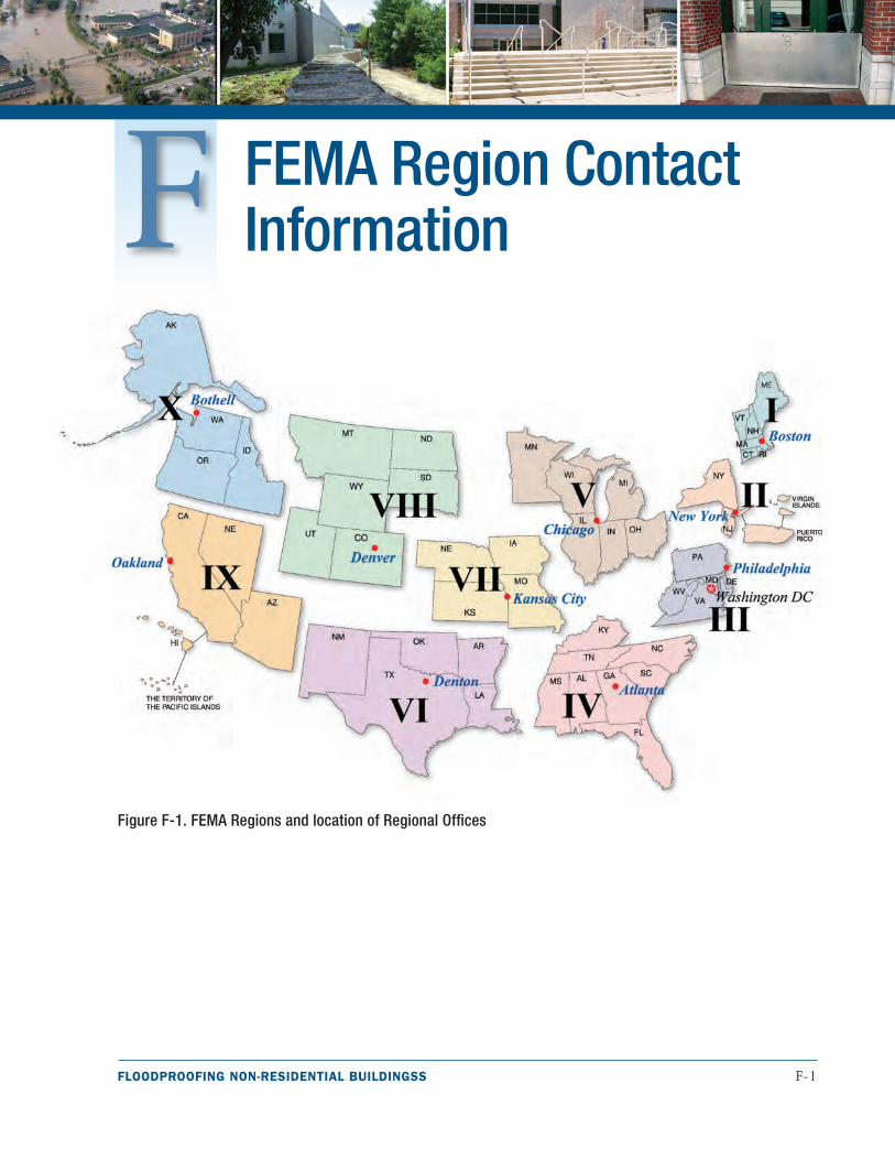
FLOODPROOFING NON-RESIDENTIAL BUILDINGSS F-1
FEMA Region Contact Information
Figure F-1. FEMA Regions and location of Regional Offices
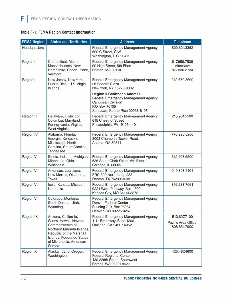
F-2 FLOODPROOFING NON-RESIDENTIAL BUILDINGS
F FEMA REGION CONTACT INFORMATION
Table F-1. FEMA Region Contact Information
FEMA Region States and Territories Address TelephoneHeadquarters Federal Emergency Management Agency
500 C Street, S.W. Washington, D.C. 20472
800.621.3362
Region I Connecticut, Maine, Massachusetts, New Hampshire, Rhode Island, Vermont
Federal Emergency Management Agency 99 High Street, 5th Floor Boston, MA 02110
617.956.7506 Alternate:
877.336.2734
Region II New Jersey, New York, Puerto Rico, U.S. Virgin Islands
Federal Emergency Management Agency 26 Federal Plaza New York, NY 10278-0002
Region II Caribbean Address Federal Emergency Management Agency Caribbean Division P.O. Box 70105 San Juan, Puerto Rico 00936-8105
212.680.3600
Region III Delaware, District of Columbia, Maryland, Pennsylvania, Virginia, West Virginia
Federal Emergency Management Agency 615 Chestnut Street Philadelphia, PA 19106-4404
215.931.5500
Region IV Alabama, Florida, Georgia, Kentucky, Mississippi, North Carolina, South Carolina, Tennessee
Federal Emergency Management Agency 3003 Chamblee Tucker Road Atlanta, GA 30341
770.220.5200
Region V Illinois, Indiana, Michigan, Minnesota, Ohio, Wisconsin
Federal Emergency Management Agency 536 South Clark Street, 6th Floor Chicago, IL 60605
312.408.5500
Region VI Arkansas, Louisiana, New Mexico, Oklahoma, Texas
Federal Emergency Management Agency FRC 800 North Loop 288 Denton, TX 76209-3698
940.898.5104
Region VII Iowa, Kansas, Missouri, Nebraska
Federal Emergency Management Agency 9221 Ward Parkway, Suite 300 Kansas City, MO 64114-3372
816.283.7061
Region VIII Colorado, Montana, South Dakota, Utah, Wyoming
Federal Emergency Management Agency Denver Federal Center Building 710, Box 25267 Denver, CO 80225-0267
Region IX Arizona, California, Guam, Hawaii, Nevada, Commonwealth of Northern Mariana Islands, Republic of the Marshall Islands, Federated States of Micronesia, American Samoa
Federal Emergency Management Agency 1111 Broadway, Suite 1200 Oakland, CA 94607-4052
510.627.7100
Pacific Area Office: 808.851.7900
Region X Alaska, Idaho, Oregon, Washington
Federal Emergency Management Agency Federal Regional Center 130 228th Street, Southwest Bothell, WA 98201-8627
425.487.4600