Embed Size (px)
Citation preview
FloodwallsBest Practices in Dam and Levee Safety Risk AnalysisPart E – Concrete StructuresChapter E-8Last modified June 2017, presented July 2019
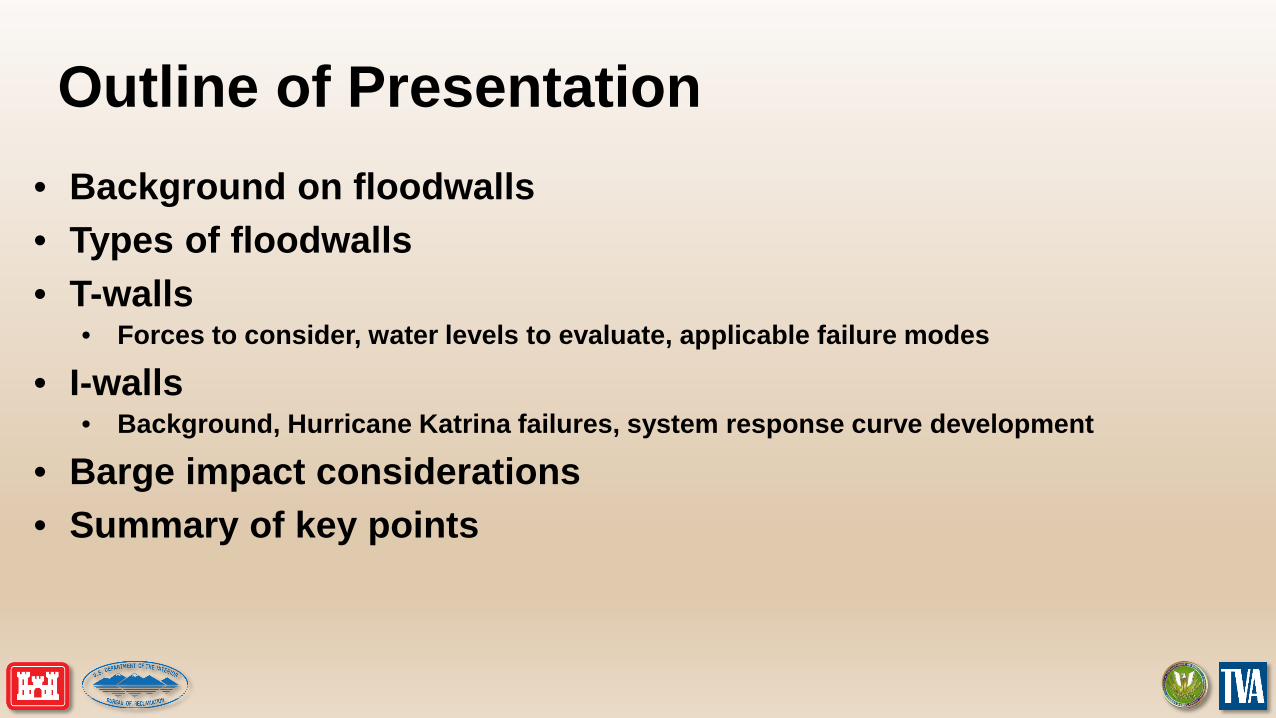
Outline of Presentation• Background on floodwalls• Types of floodwalls• T-walls
• Forces to consider, water levels to evaluate, applicable failure modes
• I-walls• Background, Hurricane Katrina failures, system response curve development
• Barge impact considerations• Summary of key points
Background Information• Local flood protection projects (LFPP) utilize both
embankment levees and floodwalls for flood prevention• Floodwalls generally used when space is limited and
embankment section is too large to reach desired height of protection
• Much more prevalent in urban/industrial areas because of space restrictions
• There are a variety of floodwall types in existence and each has unique performance characteristics
4
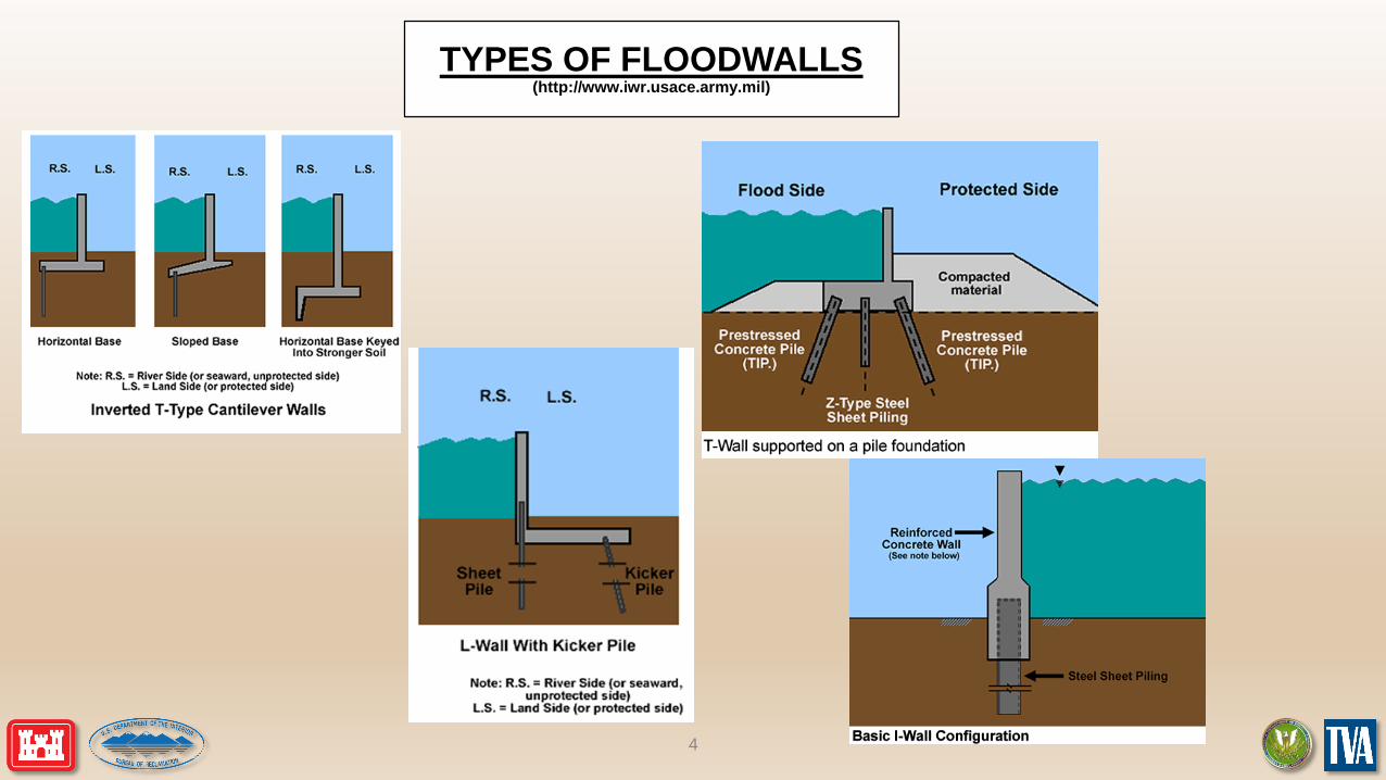
TYPES OF FLOODWALLS(http://www.iwr.usace.army.mil)
5
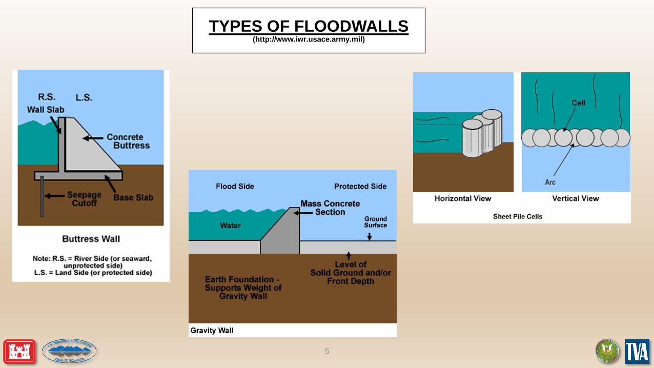
TYPES OF FLOODWALLS(http://www.iwr.usace.army.mil)
More Info on Floodwall Types• Overwhelming majority of floodwalls in service within the US are composed of T-walls
and I-walls. These are the focus of the Best Practices Manual and this presentation• L-walls have similar considerations as T-walls with respect to most performance
considerations• Multiple sources for analysis techniques of gravity walls and other important
considerations• USACE Engineering Manual 1110-2-2100• Reclamation Design Criteria for Concrete Retaining Walls
• Multiple sources for sheet pile cells including USACE engineering manual 1110-2-2503
• EM 1110-2-2502 also has general information related to other wall types when these are encountered
6
7
T-WALLS• T-walls take their name by the cross-section (inverted “T”)• Generally used when exposed height of wall becomes too excessive for an
I-wall, which is a cheaper construction alternative• Usually only a review of the as-built plans will let you know if you have a T-
wall or I-wall section as they look the same above ground• Multiple configurations possible based upon site conditions
• Horizontal base, sloped base• Sheetpile cutoff for underseepage control, no sheetpile• Shear key, no shear key• Pile founded, no piles
• Generally have performed well assuming proper design assumptions. Performed well during Hurricane Katrina.
8
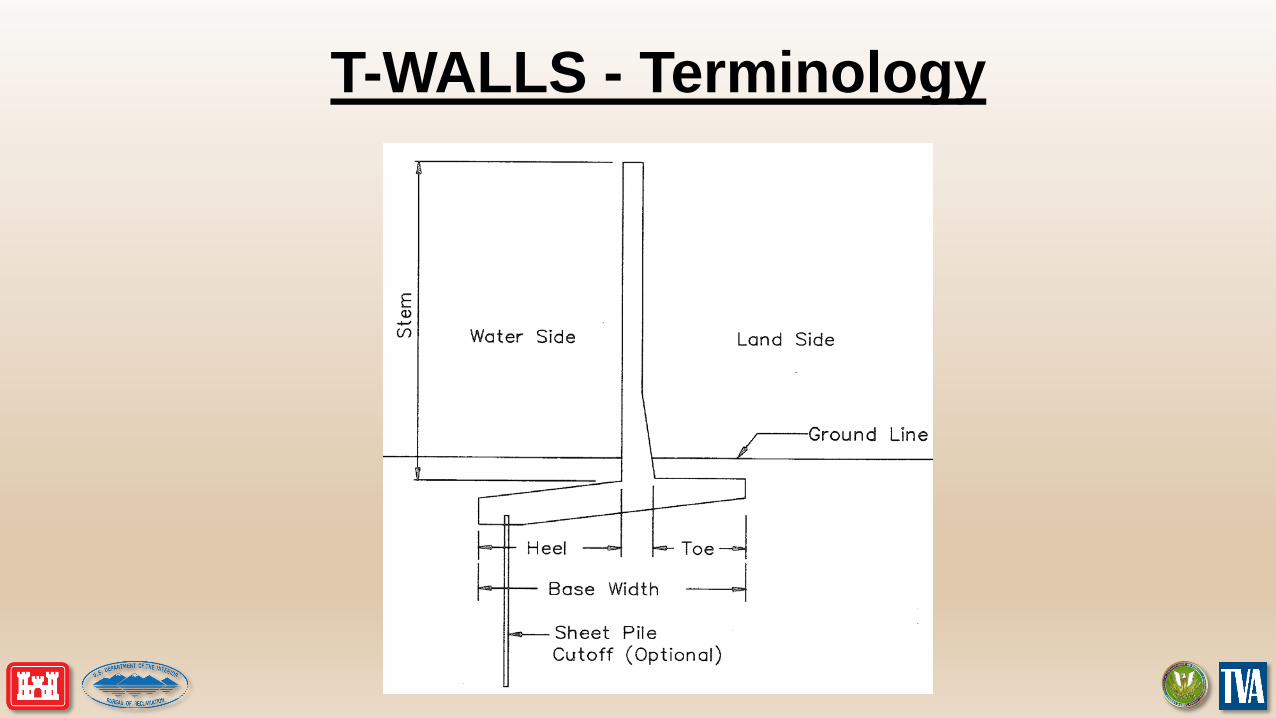
T-WALLS - Terminology
9
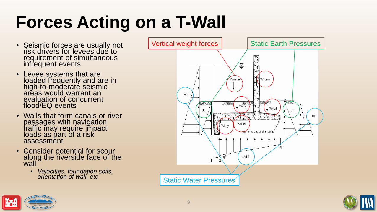
Forces Acting on a T-Wall• Seismic forces are usually not
risk drivers for levees due to requirement of simultaneous infrequent events
• Levee systems that are loaded frequently and are in high-to-moderate seismic areas would warrant an evaluation of concurrent flood/EQ events
• Walls that form canals or river passages with navigation traffic may require impact loads as part of a risk assessment
• Consider potential for scour along the riverside face of the wall
• Velocities, foundation soils, orientation of wall, etc
Vertical weight forces Static Earth Pressures
Static Water Pressures
10
Underseepage Considerations• General seepage considerations covered elsewhere in Best Practices• Types of underseepage control measures for T-walls
• Sheetpile cutoff below shear keys are fairly common• Landside toe drains are often used as an extra safety measure• Riverside impervious blanket• Landside seepage berm
• Sheetpile walls will not totally cutoff underseepage but will help performance tremendously if driven through pervious stratum or deep enough to significantly lengthen the seepage path.
• Important considerations:• What is the condition of the underseepage control system? Is it well maintained and operating as
intended?• What were the original design assumptions regarding underseepage?• Advised to work closely with your geotechnical engineer on the team
• If risk estimate is sensitive to seepage conditions, sensitivity studies can be performed to capture uncertainty.
11
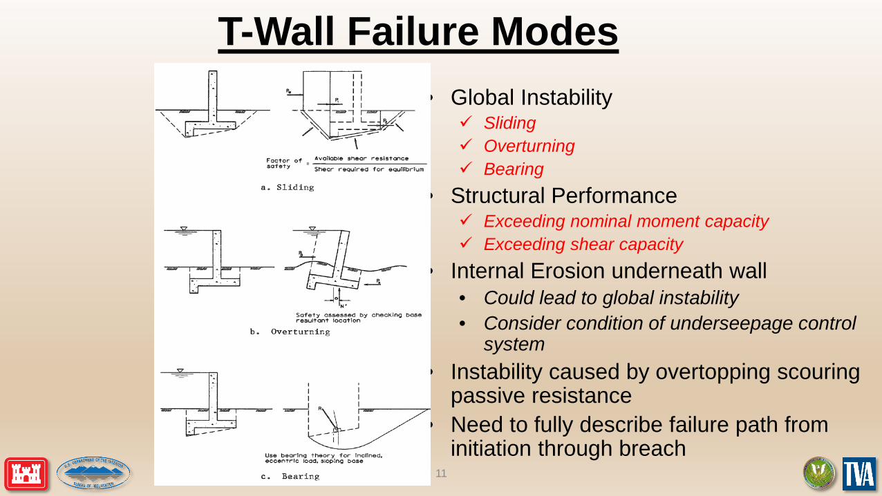
T-Wall Failure Modes• Global Instability
Sliding Overturning Bearing
• Structural Performance Exceeding nominal moment capacity Exceeding shear capacity
• Internal Erosion underneath wall• Could lead to global instability• Consider condition of underseepage control
system• Instability caused by overtopping scouring
passive resistance• Need to fully describe failure path from
initiation through breach
12
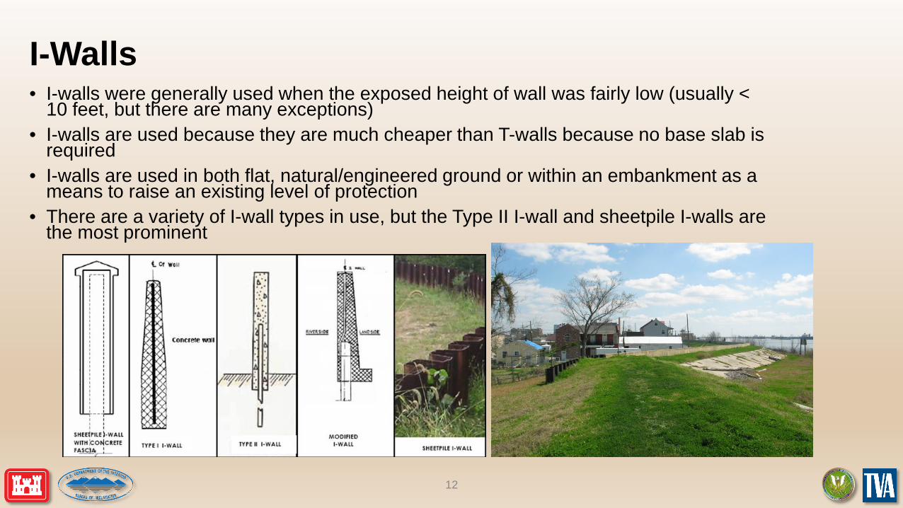
I-Walls• I-walls were generally used when the exposed height of wall was fairly low (usually <
10 feet, but there are many exceptions) • I-walls are used because they are much cheaper than T-walls because no base slab is
required• I-walls are used in both flat, natural/engineered ground or within an embankment as a
means to raise an existing level of protection• There are a variety of I-wall types in use, but the Type II I-wall and sheetpile I-walls are
the most prominent
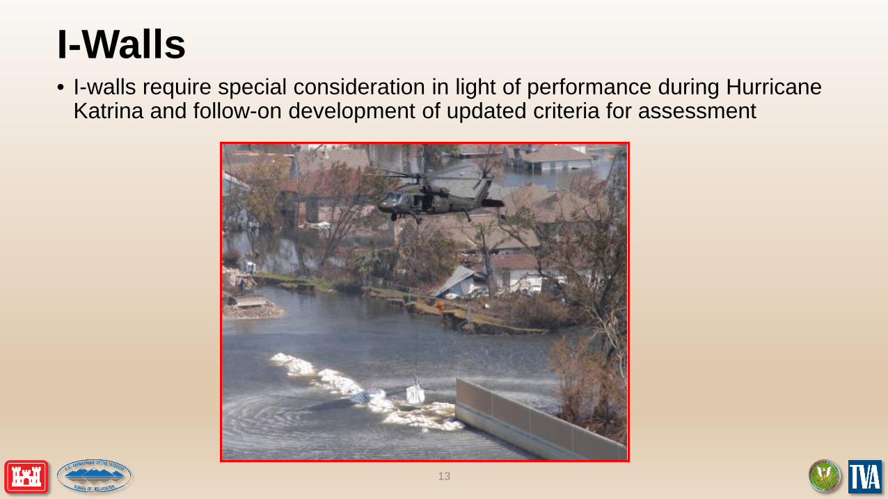
I-Walls• I-walls require special consideration in light of performance during Hurricane
Katrina and follow-on development of updated criteria for assessment
13
I-Walls Failures in New Orleans• There were multiple I-wall failures during Hurricane Katrina• A thorough detailed field investigation and follow-on analysis was carried out on
the various I-wall failures. Advanced FEM and laboratory centrifuge testing were used to help verify the cause of the failures.
• Failures of New Orleans I-walls were mainly caused by two issues:• Overtopping of wall causing scour and loss of wall support on the passive side (Lower 9th
Ward); thus, the wall protected up to its full height but breached after it was overtopped• Formation of a flood side gap against the wall causing fully hydrostatic head along the face
of the wall down to the depth of the crack (London Avenue wall failure)• The foundation conditions at New Orleans were the primary issue causing the formation of
the flood side gap
14
Updated I-Wall Guidance• Multi-discipline, multiple phase analysis used to develop new
guidance for assessing I-walls within the USACE inventory• New guidance – Engineering Technical Letter (ETL) 1105-2-
575• Failure modes should include rotational instability, translational/deep-
seated instability, and underseepage• Rotational instability is dominant failure mode for most situations• Translational instability is controlling failure mode for I-walls founded
in soft clays or a stiff clay overtop of a soft clay• Both drained and undrained soil conditions should be considered• Flood side gap analysis is applicable for undrained soil conditions• USACE program CWALSHT is a freely accessible program that can
be used to assess stability for drained soil conditions• CWALSHT can overestimate resistance provided by soft clays and a
new methodology within ETL 575 is provided to account for this condition
• Wall friction can be important and should be included in analysis• Much more guidance provided in ETL 575
15

Forces acting on I-Walls
17
Water Levels for Evaluation• Not always ‘straight forward’ for levee floodwalls
• Where is the ‘critical’ wall section?• Consideration of incipient overtopping location
• Water surface profile, top of levee embankment/floodwall profile• Will overtopping be considered in the evaluation?
• Usually will need to evaluate the wall for multiple water levels• General rule of thumb ¼, ½, ¾, 90% of exposed height, and to the top of the wall relative
to the overtopping location along the LFPP
• The water levels evaluated need to also consider what is being considered as part of the consequences for the risk analysis
18
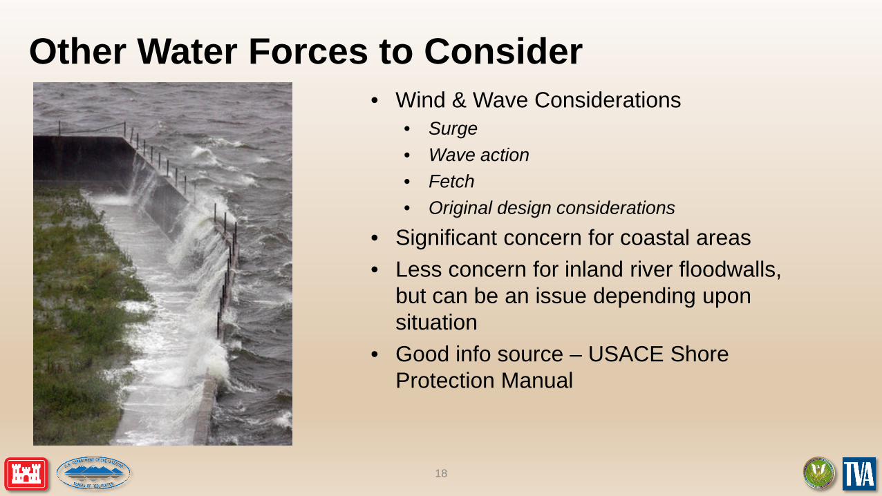
Other Water Forces to Consider• Wind & Wave Considerations
• Surge• Wave action• Fetch• Original design considerations
• Significant concern for coastal areas• Less concern for inland river floodwalls,
but can be an issue depending upon situation
• Good info source – USACE Shore Protection Manual
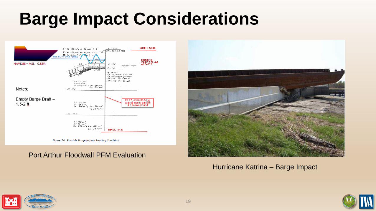
Barge Impact Considerations
19
Port Arthur Floodwall PFM EvaluationHurricane Katrina – Barge Impact
20
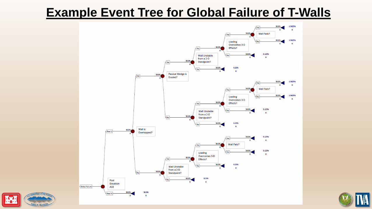
Example Event Tree for Global Failure of T-Walls
21
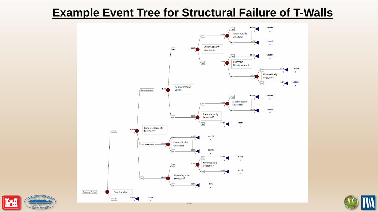
Example Event Tree for Structural Failure of T-Walls

22
Example Event Tree for I-Walls
23
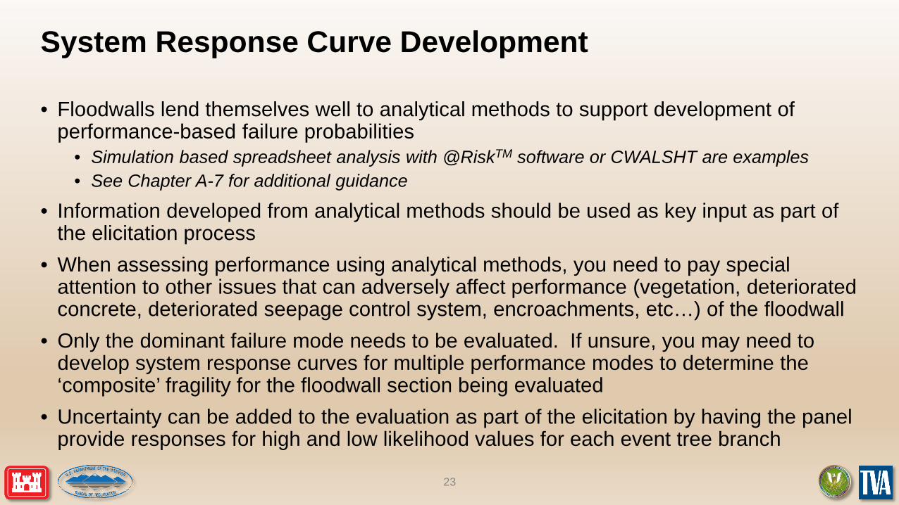
System Response Curve Development
• Floodwalls lend themselves well to analytical methods to support development of performance-based failure probabilities
• Simulation based spreadsheet analysis with @RiskTM software or CWALSHT are examples• See Chapter A-7 for additional guidance
• Information developed from analytical methods should be used as key input as part of the elicitation process
• When assessing performance using analytical methods, you need to pay special attention to other issues that can adversely affect performance (vegetation, deteriorated concrete, deteriorated seepage control system, encroachments, etc…) of the floodwall
• Only the dominant failure mode needs to be evaluated. If unsure, you may need to develop system response curves for multiple performance modes to determine the ‘composite’ fragility for the floodwall section being evaluated
• Uncertainty can be added to the evaluation as part of the elicitation by having the panel provide responses for high and low likelihood values for each event tree branch

24
Simple Example of System Response for Floodwall
EL 20.0
EL 4.0
EL 2.0
EL 0.0
Key Takeaways• Multiple types of floodwalls exist, majority are T-walls and I-walls• Many of the forces acting on walls are the same whether they are T-walls
or I-walls, but failure modes vary between the 2 types• Both types of walls lend themselves well to a risk-based analysis approach
that can help serve as the ‘backbone’ of the development of the system response curve
• Relatively recent performance of I-walls and subsequent analysis have identified specific failure modes when certain types of foundations are present
• There are multiple detailed references freely available to help support any level of analysis to be carried out, but the level of effort needs to be commensurate with the overall purpose of the evaluation
25


![diseño de pequeñas presas [bureau of reclamation]](https://img.pdfslide.net/doc/110x75/55cfe3ae5503467d968b58c5/diseno-de-pequenas-presas-bureau-of-reclamation.jpg)