Embed Size (px)
Citation preview

AASHTOWare BrD/BrR 6.8
Floor System Tutorial
FS4 – Skewed End Panel Floor System Example
FS4 – Skewed End Panel Floor System Example
Last Modified: 8/30/2016 1
Topics Covered
Superstructure composed of girders, floorbeams and stringers
System Superstructure Definition
Skewed end panels
Mirroring stringer group definitions when they are assigned to stringer units
This example demonstrates entering a Girder-Floorbeam-Stringer superstructure with skewed end panels in BrR
using the System superstructure definition approach. The focus of this example is the skewed end panels and
geometry of the system. It is assumed that the user of this example is an advanced user who is familiar with the
basics of BrR. As such, the details of creating bridge materials, beam shapes, etc., are not presented in great detail
in this example.
If you have already completed example problem “FS1-GirderFloorbeamStringer Example”, you can open the bridge
you created in that example and jump to Page FS5-5 to start this example. If you have not completed “FS1-
GirderFloorbeamStringer Example”, continue with this page.
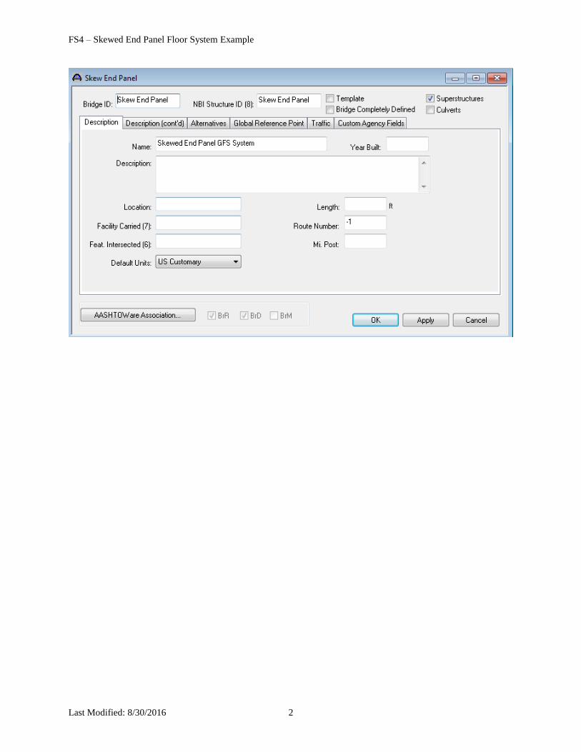
From the Bridge Explorer, select File/New/New Bridge to create a new bridge. Enter the following description data:
FS4 – Skewed End Panel Floor System Example
Last Modified: 8/30/2016 2
FS4 – Skewed End Panel Floor System Example
Last Modified: 8/30/2016 3
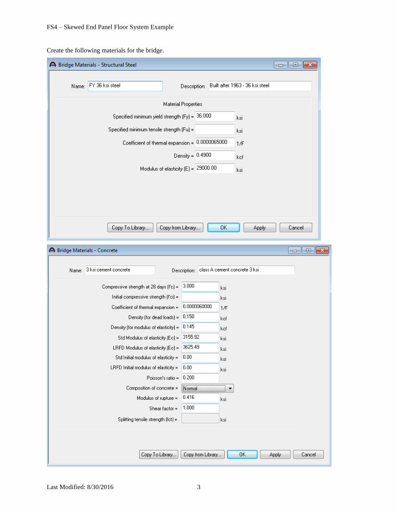
Create the following materials for the bridge.
FS4 – Skewed End Panel Floor System Example
Last Modified: 8/30/2016 4
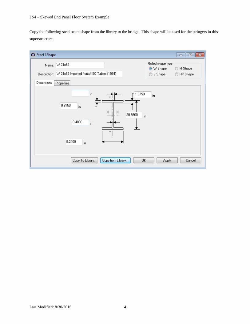
Copy the following steel beam shape from the library to the bridge. This shape will be used for the stringers in this
superstructure.
FS4 – Skewed End Panel Floor System Example
Last Modified: 8/30/2016 5
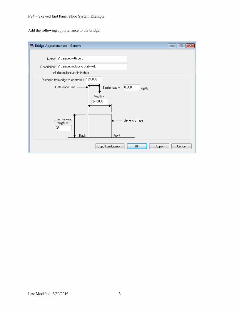
Add the following appurtenance to the bridge.
FS4 – Skewed End Panel Floor System Example
Last Modified: 8/30/2016 6
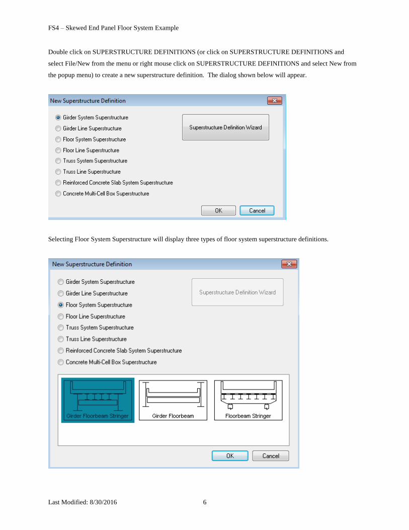
Double click on SUPERSTRUCTURE DEFINITIONS (or click on SUPERSTRUCTURE DEFINITIONS and
select File/New from the menu or right mouse click on SUPERSTRUCTURE DEFINITIONS and select New from
the popup menu) to create a new superstructure definition. The dialog shown below will appear.
Selecting Floor System Superstructure will display three types of floor system superstructure definitions.
FS4 – Skewed End Panel Floor System Example
Last Modified: 8/30/2016 7
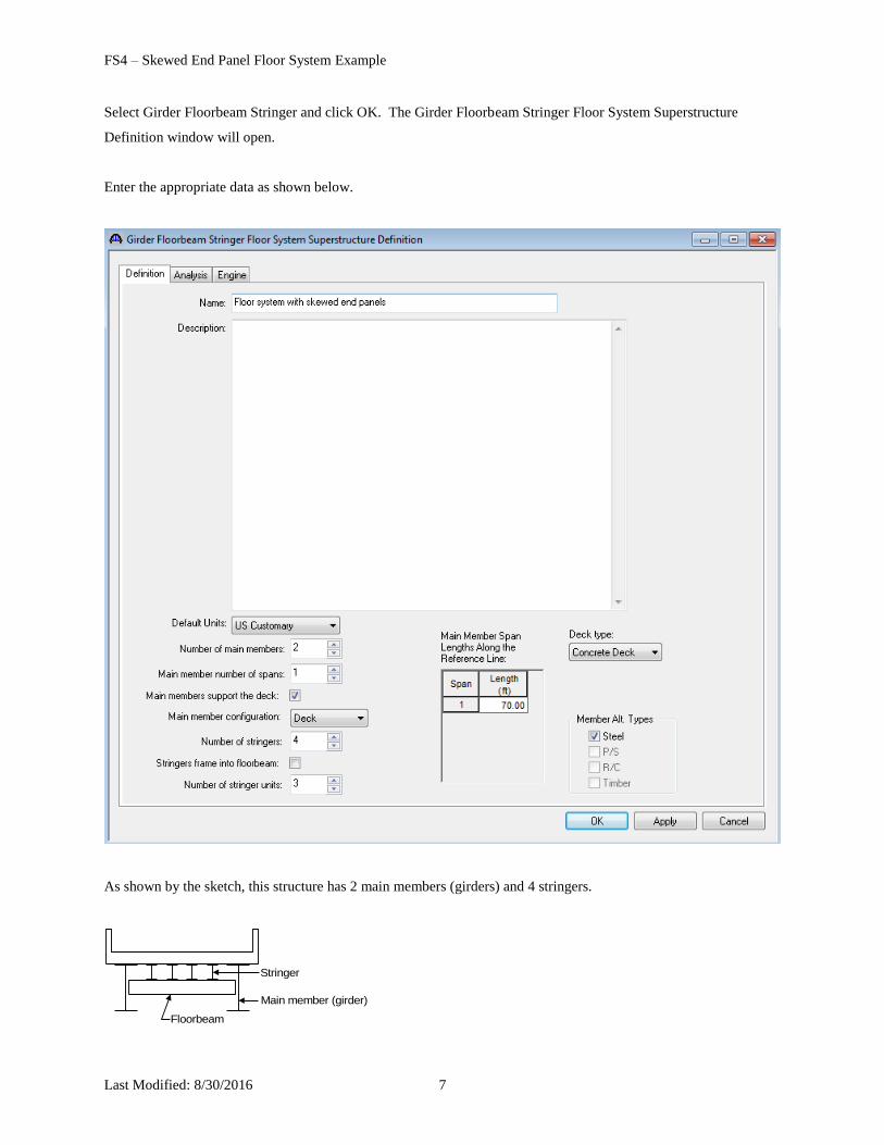
Select Girder Floorbeam Stringer and click OK. The Girder Floorbeam Stringer Floor System Superstructure
Definition window will open.
Enter the appropriate data as shown below.
As shown by the sketch, this structure has 2 main members (girders) and 4 stringers.
Main member (girder)
Floorbeam
Stringer
FS4 – Skewed End Panel Floor System Example
Last Modified: 8/30/2016 8
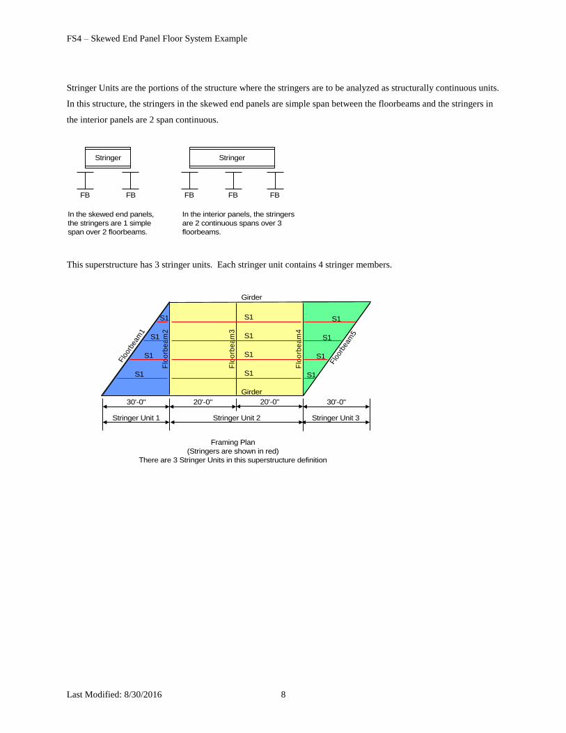
Stringer Units are the portions of the structure where the stringers are to be analyzed as structurally continuous units.
In this structure, the stringers in the skewed end panels are simple span between the floorbeams and the stringers in
the interior panels are 2 span continuous.
In the interior panels, the stringers
are 2 continuous spans over 3
floorbeams.
FBFB FB
Stringer
In the skewed end panels,
the stringers are 1 simple
span over 2 floorbeams.
FBFB
Stringer
This superstructure has 3 stringer units. Each stringer unit contains 4 stringer members.
Framing Plan
(Stringers are shown in red)
There are 3 Stringer Units in this superstructure definition
Stringer Unit 1 Stringer Unit 2
Flo
orbe
am1
Flo
orb
ea
m4
Flo
orb
ea
m2
Flo
orb
ea
m3
Flo
orbe
am5
Stringer Unit 3
30'-0" 30'-0"20'-0"
S1
S1
S1
S1
20'-0"
S1
S1
S1
S1
S1
S1
S1
S1
Girder
Girder
FS4 – Skewed End Panel Floor System Example
Last Modified: 8/30/2016 9
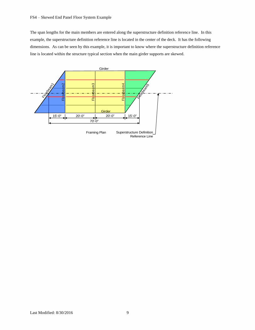
The span lengths for the main members are entered along the superstructure definition reference line. In this
example, the superstructure definition reference line is located in the center of the deck. It has the following
dimensions. As can be seen by this example, it is important to know where the superstructure definition reference
line is located within the structure typical section when the main girder supports are skewed.
Framing Plan
Flo
orbe
am1
Flo
orb
ea
m4
Flo
orb
ea
m2
Flo
orb
ea
m3
Flo
orbe
am5
15'-0" 15'-0"20'-0" 20'-0"
Girder
Girder
Superstructure Definition
Reference Line
70'-0"
FS4 – Skewed End Panel Floor System Example
Last Modified: 8/30/2016 10
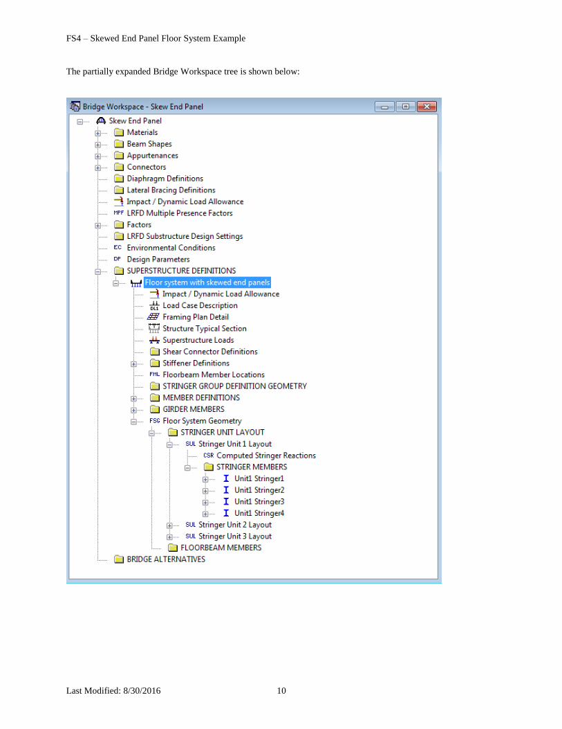
The partially expanded Bridge Workspace tree is shown below:
FS4 – Skewed End Panel Floor System Example
Last Modified: 8/30/2016 11
This example does not cover creating a Bridge Alternative, Superstructure or Superstructure Alternative as those
windows have been covered in numerous other examples. We will continue with describing this superstructure
definition.
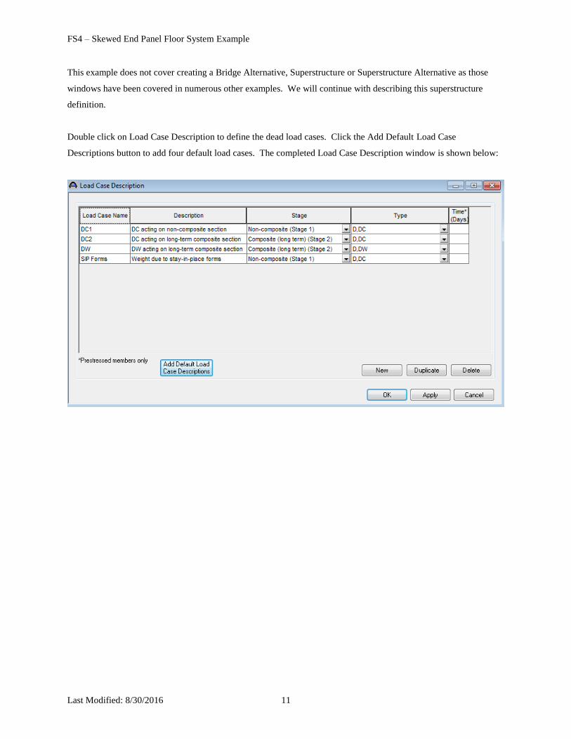
Double click on Load Case Description to define the dead load cases. Click the Add Default Load Case
Descriptions button to add four default load cases. The completed Load Case Description window is shown below:
FS4 – Skewed End Panel Floor System Example
Last Modified: 8/30/2016 12
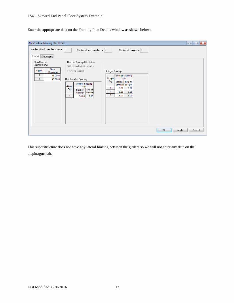
Enter the appropriate data on the Framing Plan Details window as shown below:
This superstructure does not have any lateral bracing between the girders so we will not enter any data on the
diaphragms tab.
FS4 – Skewed End Panel Floor System Example
Last Modified: 8/30/2016 13
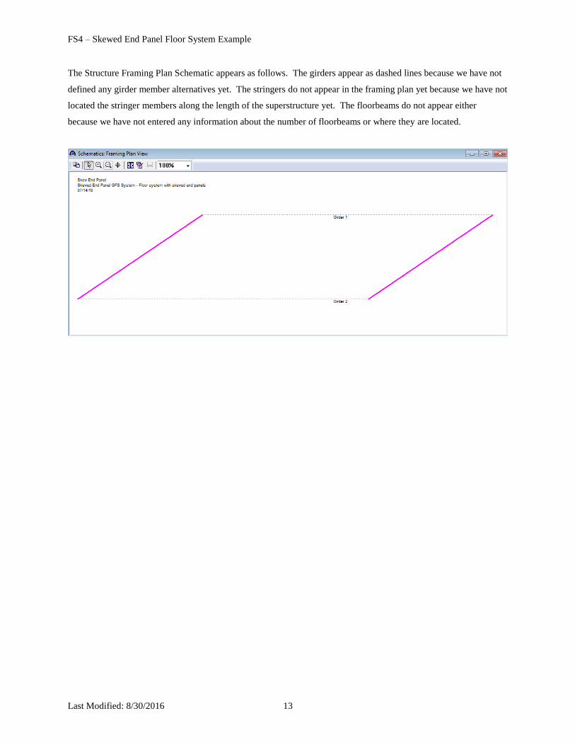
The Structure Framing Plan Schematic appears as follows. The girders appear as dashed lines because we have not
defined any girder member alternatives yet. The stringers do not appear in the framing plan yet because we have not
located the stringer members along the length of the superstructure yet. The floorbeams do not appear either
because we have not entered any information about the number of floorbeams or where they are located.
FS4 – Skewed End Panel Floor System Example
Last Modified: 8/30/2016 14
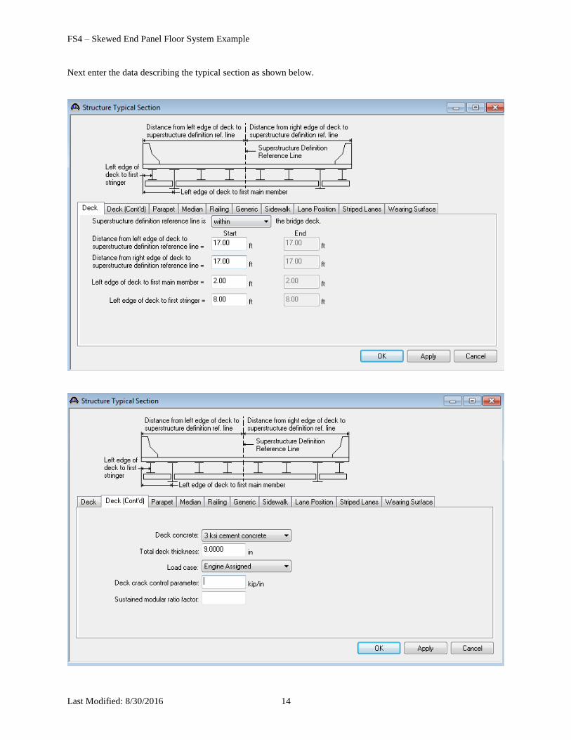
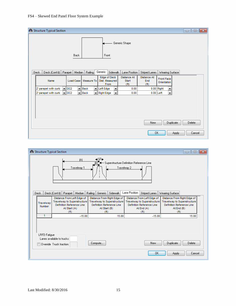
Next enter the data describing the typical section as shown below.
FS4 – Skewed End Panel Floor System Example
Last Modified: 8/30/2016 15
FS4 – Skewed End Panel Floor System Example
Last Modified: 8/30/2016 16
This superstructure does not contain any transverse or bearing stiffeners so we will not create any stiffener
definitions.
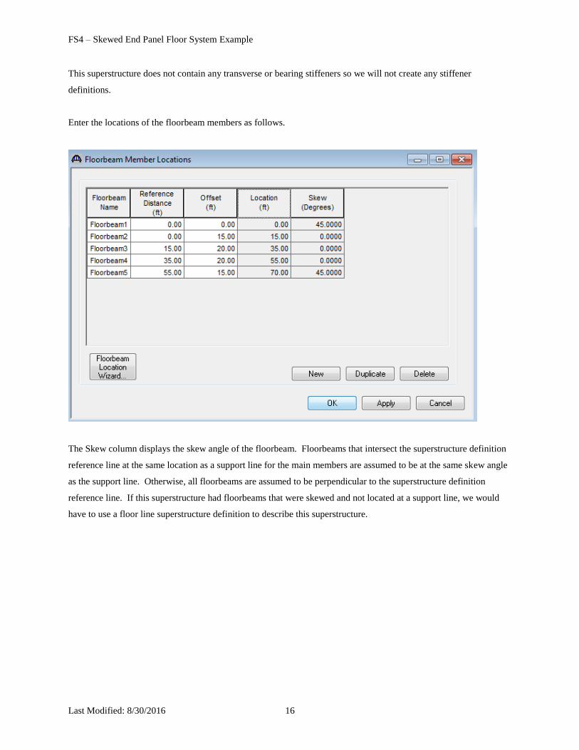
Enter the locations of the floorbeam members as follows.
The Skew column displays the skew angle of the floorbeam. Floorbeams that intersect the superstructure definition
reference line at the same location as a support line for the main members are assumed to be at the same skew angle
as the support line. Otherwise, all floorbeams are assumed to be perpendicular to the superstructure definition
reference line. If this superstructure had floorbeams that were skewed and not located at a support line, we would
have to use a floor line superstructure definition to describe this superstructure.
FS4 – Skewed End Panel Floor System Example
Last Modified: 8/30/2016 17
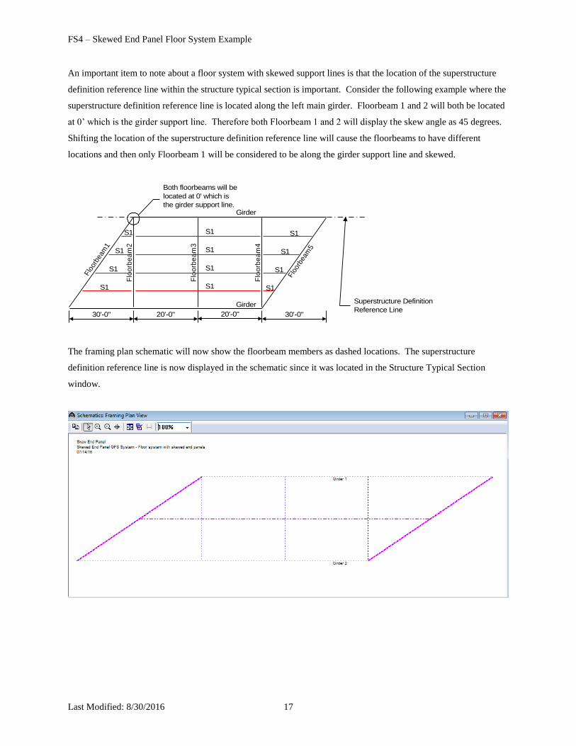
An important item to note about a floor system with skewed support lines is that the location of the superstructure
definition reference line within the structure typical section is important. Consider the following example where the
superstructure definition reference line is located along the left main girder. Floorbeam 1 and 2 will both be located
at 0’ which is the girder support line. Therefore both Floorbeam 1 and 2 will display the skew angle as 45 degrees.
Shifting the location of the superstructure definition reference line will cause the floorbeams to have different
locations and then only Floorbeam 1 will be considered to be along the girder support line and skewed.
Flo
orbe
am1
Flo
orb
ea
m4
Flo
orb
ea
m2
Flo
orb
ea
m3
Flo
orbe
am5
30'-0" 30'-0"20'-0"
S1
S1
S1
S1
20'-0"
S1
S1
S1
S1
S1
S1
S1
S1
Girder
GirderSuperstructure Definition
Reference Line
Both floorbeams will be
located at 0' which is
the girder support line.
The framing plan schematic will now show the floorbeam members as dashed locations. The superstructure
definition reference line is now displayed in the schematic since it was located in the Structure Typical Section
window.
FS4 – Skewed End Panel Floor System Example
Last Modified: 8/30/2016 18
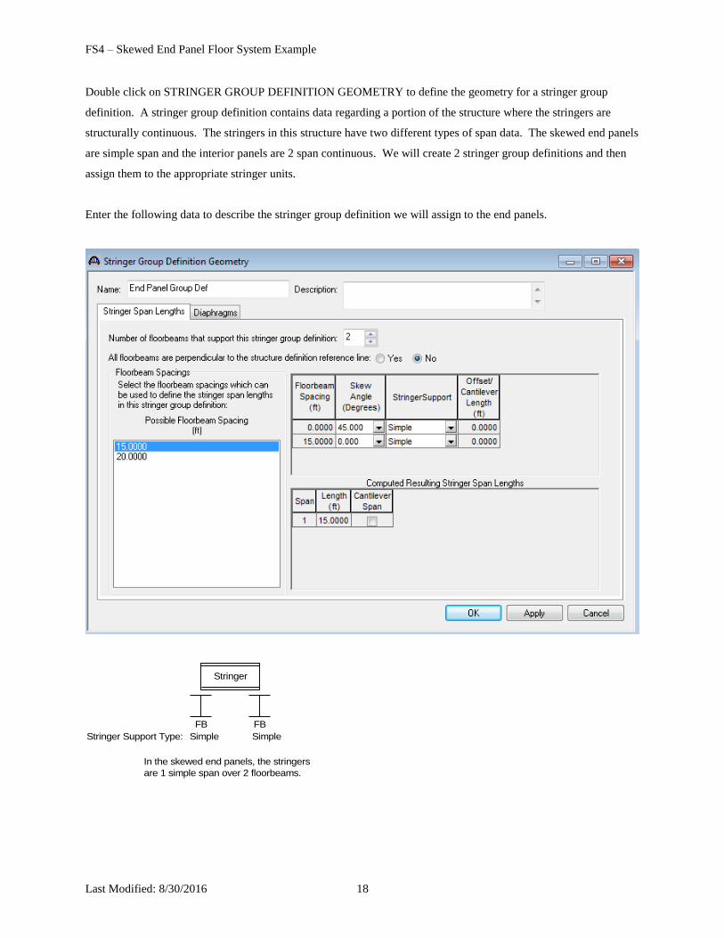
Double click on STRINGER GROUP DEFINITION GEOMETRY to define the geometry for a stringer group
definition. A stringer group definition contains data regarding a portion of the structure where the stringers are
structurally continuous. The stringers in this structure have two different types of span data. The skewed end panels
are simple span and the interior panels are 2 span continuous. We will create 2 stringer group definitions and then
assign them to the appropriate stringer units.
Enter the following data to describe the stringer group definition we will assign to the end panels.
In the skewed end panels, the stringers
are 1 simple span over 2 floorbeams.
FBFB
Stringer
Simple SimpleStringer Support Type:
FS4 – Skewed End Panel Floor System Example
Last Modified: 8/30/2016 19
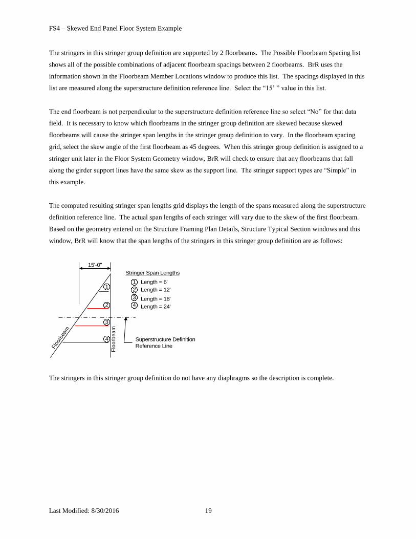
The stringers in this stringer group definition are supported by 2 floorbeams. The Possible Floorbeam Spacing list
shows all of the possible combinations of adjacent floorbeam spacings between 2 floorbeams. BrR uses the
information shown in the Floorbeam Member Locations window to produce this list. The spacings displayed in this
list are measured along the superstructure definition reference line. Select the “15’ ” value in this list.
The end floorbeam is not perpendicular to the superstructure definition reference line so select “No” for that data
field. It is necessary to know which floorbeams in the stringer group definition are skewed because skewed
floorbeams will cause the stringer span lengths in the stringer group definition to vary. In the floorbeam spacing
grid, select the skew angle of the first floorbeam as 45 degrees. When this stringer group definition is assigned to a
stringer unit later in the Floor System Geometry window, BrR will check to ensure that any floorbeams that fall
along the girder support lines have the same skew as the support line. The stringer support types are “Simple” in
this example.
The computed resulting stringer span lengths grid displays the length of the spans measured along the superstructure
definition reference line. The actual span lengths of each stringer will vary due to the skew of the first floorbeam.
Based on the geometry entered on the Structure Framing Plan Details, Structure Typical Section windows and this
window, BrR will know that the span lengths of the stringers in this stringer group definition are as follows:
Flo
orbe
am
Flo
orb
ea
m
15'-0"
Superstructure Definition
Reference Line
1
2
3
4
1
2
3
4
Length = 6'
Length = 12'
Length = 18'
Length = 24'
Stringer Span Lengths
The stringers in this stringer group definition do not have any diaphragms so the description is complete.
FS4 – Skewed End Panel Floor System Example
Last Modified: 8/30/2016 20
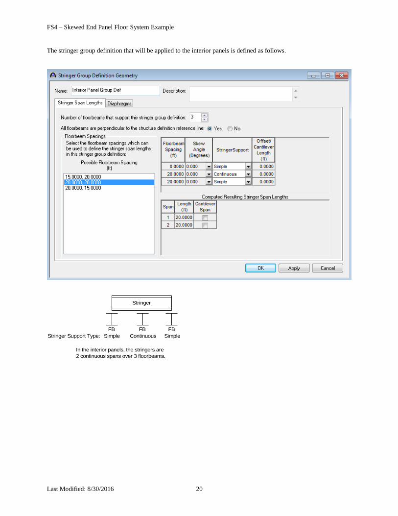
The stringer group definition that will be applied to the interior panels is defined as follows.
In the interior panels, the stringers are
2 continuous spans over 3 floorbeams.
FBFB FB
Stringer
Simple SimpleStringer Support Type: Continuous
FS4 – Skewed End Panel Floor System Example
Last Modified: 8/30/2016 21
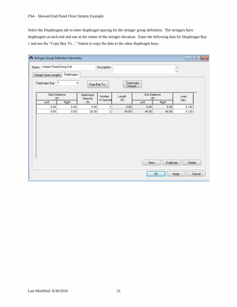
Select the Diaphragms tab to enter diaphragm spacing for the stringer group definition. The stringers have
diaphragms at each end and one at the center of the stringer elevation. Enter the following data for Diaphragm Bay
1 and use the “Copy Bay To…” button to copy the data to the other diaphragm bays.
FS4 – Skewed End Panel Floor System Example
Last Modified: 8/30/2016 22
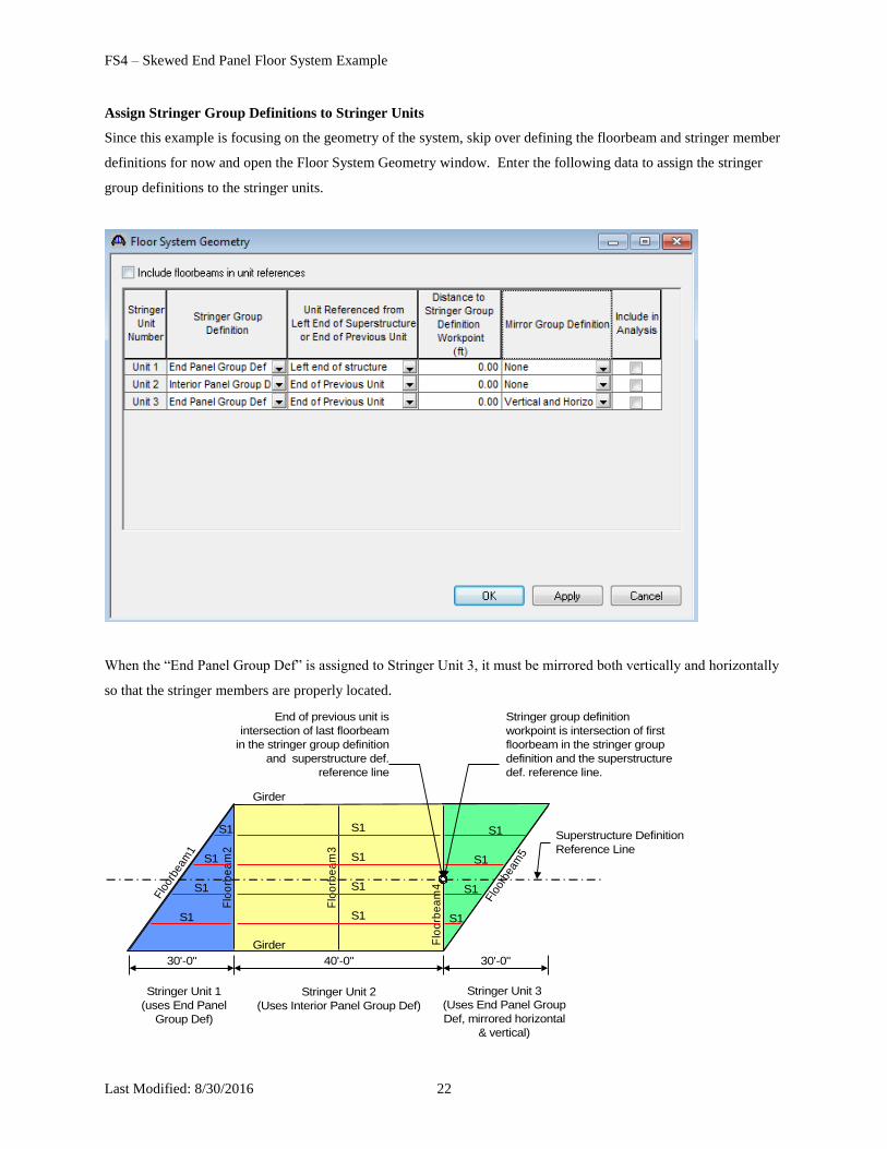
Assign Stringer Group Definitions to Stringer Units
Since this example is focusing on the geometry of the system, skip over defining the floorbeam and stringer member
definitions for now and open the Floor System Geometry window. Enter the following data to assign the stringer
group definitions to the stringer units.
When the “End Panel Group Def” is assigned to Stringer Unit 3, it must be mirrored both vertically and horizontally
so that the stringer members are properly located.
Stringer Unit 1
(uses End Panel
Group Def)
Stringer Unit 2
(Uses Interior Panel Group Def)
Flo
orbe
am1
Flo
orb
ea
m4
Flo
orb
ea
m2
Flo
orb
ea
m3
Flo
orbe
am5
Stringer Unit 3
(Uses End Panel Group
Def, mirrored horizontal
& vertical)
30'-0" 30'-0"40'-0"
S1
S1
S1
S1
S1
S1
S1
S1
S1
S1
S1
S1
Girder
Girder
Superstructure Definition
Reference Line
End of previous unit is
intersection of last floorbeam
in the stringer group definition
and superstructure def.
reference line
Stringer group definition
workpoint is intersection of first
floorbeam in the stringer group
definition and the superstructure
def. reference line.
FS4 – Skewed End Panel Floor System Example
Last Modified: 8/30/2016 23
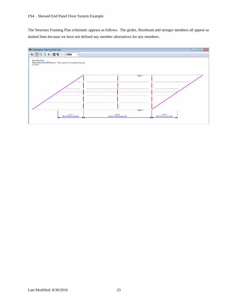
The Structure Framing Plan schematic appears as follows. The girder, floorbeam and stringer members all appear as
dashed lines because we have not defined any member alternatives for any members.
FS4 – Skewed End Panel Floor System Example
Last Modified: 8/30/2016 24
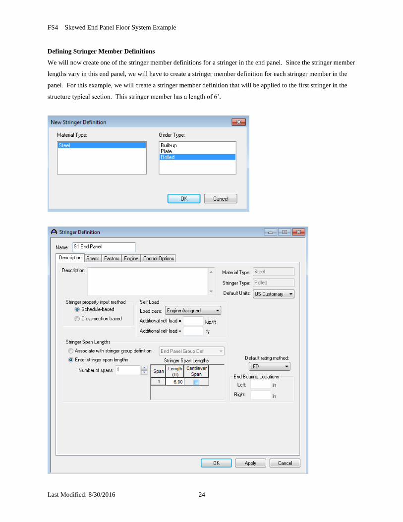
Defining Stringer Member Definitions
We will now create one of the stringer member definitions for a stringer in the end panel. Since the stringer member
lengths vary in this end panel, we will have to create a stringer member definition for each stringer member in the
panel. For this example, we will create a stringer member definition that will be applied to the first stringer in the
structure typical section. This stringer member has a length of 6’.
FS4 – Skewed End Panel Floor System Example
Last Modified: 8/30/2016 25
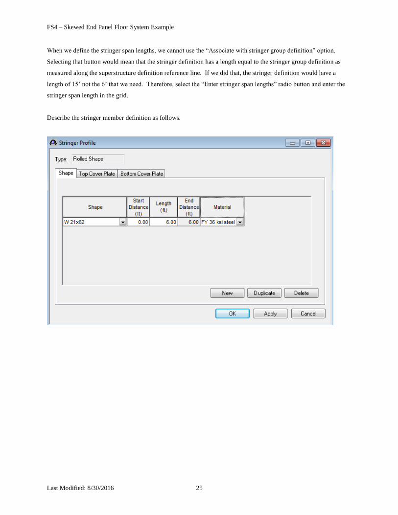
When we define the stringer span lengths, we cannot use the “Associate with stringer group definition” option.
Selecting that button would mean that the stringer definition has a length equal to the stringer group definition as
measured along the superstructure definition reference line. If we did that, the stringer definition would have a
length of 15’ not the 6’ that we need. Therefore, select the “Enter stringer span lengths” radio button and enter the
stringer span length in the grid.
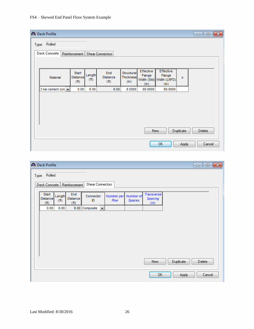
Describe the stringer member definition as follows.
FS4 – Skewed End Panel Floor System Example
Last Modified: 8/30/2016 26
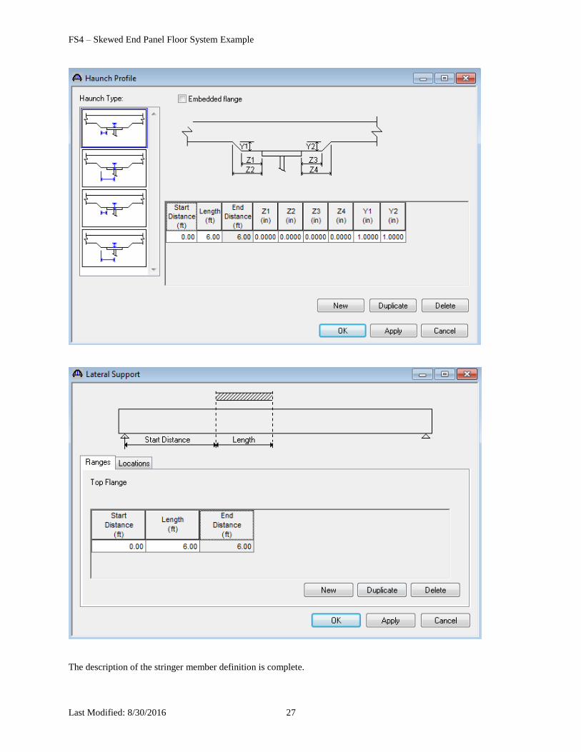
FS4 – Skewed End Panel Floor System Example
Last Modified: 8/30/2016 27
The description of the stringer member definition is complete.
FS4 – Skewed End Panel Floor System Example
Last Modified: 8/30/2016 28
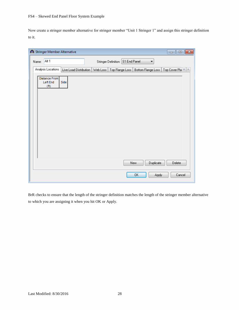
Now create a stringer member alternative for stringer member “Unit 1 Stringer 1” and assign this stringer definition
to it.
BrR checks to ensure that the length of the stringer definition matches the length of the stringer member alternative
to which you are assigning it when you hit OK or Apply.
FS4 – Skewed End Panel Floor System Example
Last Modified: 8/30/2016 29
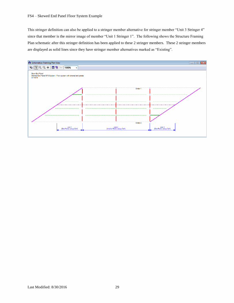
This stringer definition can also be applied to a stringer member alternative for stringer member “Unit 3 Stringer 4”
since that member is the mirror image of member “Unit 1 Stringer 1”. The following shows the Structure Framing
Plan schematic after this stringer definition has been applied to these 2 stringer members. These 2 stringer members
are displayed as solid lines since they have stringer member alternatives marked as “Existing”.
FS4 – Skewed End Panel Floor System Example
Last Modified: 8/30/2016 30
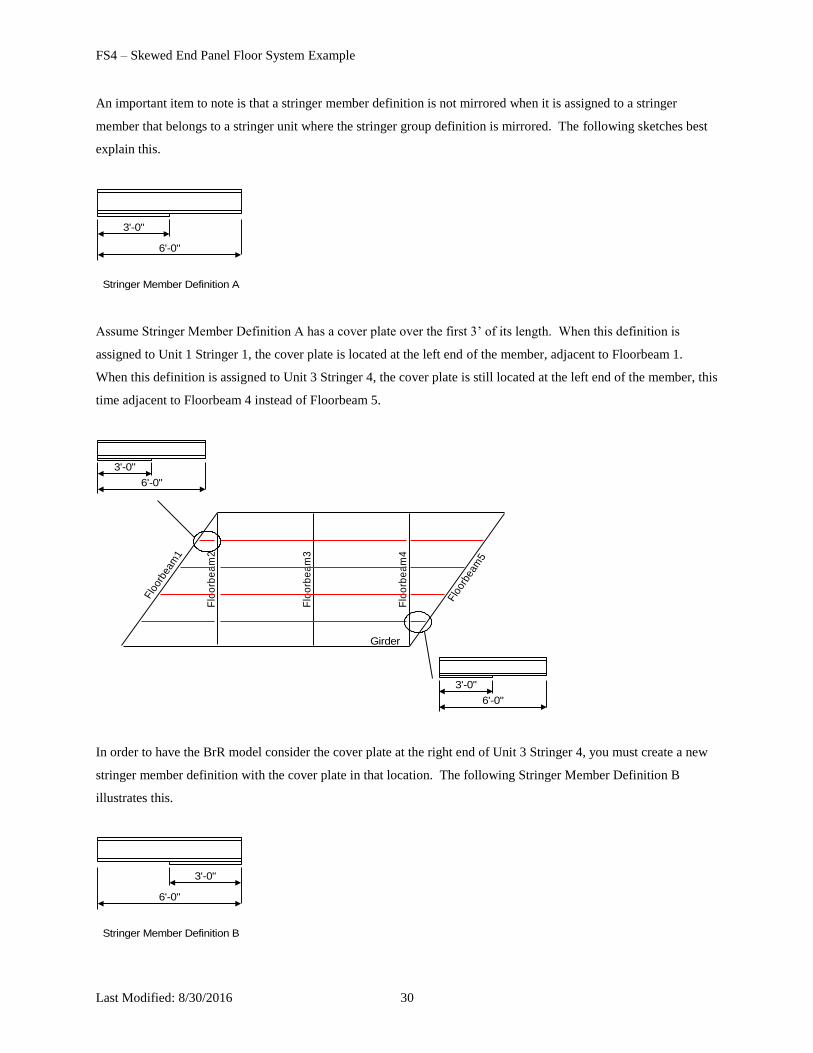
An important item to note is that a stringer member definition is not mirrored when it is assigned to a stringer
member that belongs to a stringer unit where the stringer group definition is mirrored. The following sketches best
explain this.
Stringer Member Definition A
6'-0"
3'-0"
Assume Stringer Member Definition A has a cover plate over the first 3’ of its length. When this definition is
assigned to Unit 1 Stringer 1, the cover plate is located at the left end of the member, adjacent to Floorbeam 1.
When this definition is assigned to Unit 3 Stringer 4, the cover plate is still located at the left end of the member, this
time adjacent to Floorbeam 4 instead of Floorbeam 5.
Flo
orbe
am1
Flo
orb
ea
m4
Flo
orb
ea
m2
Flo
orb
ea
m3
Flo
orbe
am5
Girder
6'-0"
3'-0"
6'-0"
3'-0"
In order to have the BrR model consider the cover plate at the right end of Unit 3 Stringer 4, you must create a new
stringer member definition with the cover plate in that location. The following Stringer Member Definition B
illustrates this.
Stringer Member Definition B
6'-0"
3'-0"
FS4 – Skewed End Panel Floor System Example
Last Modified: 8/30/2016 31
Continue with this example on your own. Create the remaining stringer and floorbeam member definitions and
assign them to the member alternatives. Create girder member alternatives for the girder members and rate the
member alternatives in this superstructure definition.