Embed Size (px)
DESCRIPTION
Floors & Trench Drains
Citation preview
ASME A112.6.3-2001(Revision and Redesignation of ASME A112.21.1M-1991)
FLOOR AND TRENCH DRAINSA N A M E R I C A N N A T I O N A L S T A N D A R D
ASME A112.6.3-2001(Revision and Redesignation of ASME A112.21.1M-1991)
FLOOR AND TRENCH DRAINSA N A M E R I C A N N A T I O N A L S T A N D A R D
Copyright ASME International Provided by IHS under license with ASME Licensee=Hong Kong Polytechnic Univ/9976803100
Not for Resale, 07/23/2009 18:23:41 MDTNo reproduction or networking permitted without license from IHS
--`,`````,``,`,`,,,,``,,`,`,,,,,-`-`,,`,,`,`,,`---
A N A M E R I C A N N A T I O N A L S T A N D A R D
FLOOR AND TRENCH DRAINS
ASME A112.6.3-2001(Revision and Redesignation of ASME A112.21.1M-1991)
Copyright ASME International Provided by IHS under license with ASME Licensee=Hong Kong Polytechnic Univ/9976803100
Not for Resale, 07/23/2009 18:23:41 MDTNo reproduction or networking permitted without license from IHS
--`,`````,``,`,`,,,,``,,`,`,,,,,-`-`,,`,,`,`,,`---
The Standard is downloaded from www.bzfxw.com Standard Sharing
Date of Issuance: November 20, 2001
The next edition of this Standard is scheduled for publication in 2005. Therewill be no addenda or written interpretations of the requirements of thisStandard issued to this edition.
ASME is the registered trademark of The American Society of Mechanical Engineers.
This code or standard was developed under procedures accredited as meeting the criteria forAmerican National Standards. The Standards Committee that approved the code or standardwas balanced to assure that individuals from competent and concerned interests have had anopportunity to participate. The proposed code or standard was made available for public reviewand comment that provides an opportunity for additional public input from industry, academia,regulatory agencies, and the public-at-large.
ASME does not “approve,” “rate,” or “endorse” any item, construction, proprietary device,or activity.
ASME does not take any position with respect to the validity of any patent rights asserted inconnection with any items mentioned in this document, and does not undertake to insure anyoneutilizing a standard against liability for infringement of any applicable letters patent, nor assumeany such liability. Users of a code or standard are expressly advised that determination of thevalidity of any such patent rights, and the risk of infringement of such rights, is entirely theirown responsibility.
Participation by federal agency representative(s) or person(s) affiliated with industry is not tobe interpreted as government or industry endorsement of this code or standard.
ASME accepts responsibility for only those interpretations of this document issued inaccordance with the established ASME procedures and policies, which precludes the issuanceof interpretations by individuals.
No part of this document may be reproduced in any form,in an electronic retrieval system or otherwise,
without the prior written permission of the publisher.
The American Society of Mechanical EngineersThree Park Avenue, New York, NY 10016-5990
Copyright © 2001 byTHE AMERICAN SOCIETY OF MECHANICAL ENGINEERS
All Rights ReservedPrinted in U.S.A.
Copyright ASME International Provided by IHS under license with ASME Licensee=Hong Kong Polytechnic Univ/9976803100
Not for Resale, 07/23/2009 18:23:41 MDTNo reproduction or networking permitted without license from IHS
--`,`````,``,`,`,,,,``,,`,`,,,,,-`-`,,`,,`,`,,`---
FOREWORD
The American National Standards Committee A112 was established on July 27, 1955for the purpose of standardizing plumbing materials and equipment. Its first organizationalmeeting was held on July 22, 1958, and Panel No. 21 was created on May 1, 1964 toestablish standards for roof drains, floor drains, backwater valves, and other drainagespecialties. Its scope was as follows: the recommendation of suitable existing standardsin cooperation with interested sponsors, or the development of adequate new standards asneeded for roof drains, floor drains, and other drains as used or installed in plumbingsystems. The committee has since been reorganized as an ASME Standards Committee.
The ASME A112 Committee was restructured in 1998 in accordance with the ASMERedesign Process, and Panel 21 Working Group 1 became Project Team 6.3. The ProjectTeam met twice to update this Standard, which now includes criteria from the InternationalAssociation of Plumbing and Mechanical Official’s (IAMPO) Product Standards PS 4 andPS 16.
Suggestions for improvement of this Standard are welcome. They should be sent to theAmerican Society of Mechanical Engineers, Three Park Avenue, New York, NY 10016-5990.
This revision and redesignation of ASME A112.21.1M-1991 was approved as an AmericanNational Standard on May 4, 2001.
iii
Copyright ASME International Provided by IHS under license with ASME Licensee=Hong Kong Polytechnic Univ/9976803100
Not for Resale, 07/23/2009 18:23:41 MDTNo reproduction or networking permitted without license from IHS
--`,`````,``,`,`,,,,``,,`,`,,,,,-`-`,,`,,`,`,,`---The Standard is downloaded from www.bzfxw.com Standard Sharing
ASME STANDARDS COMMITTEE A112Standardization of Plumbing Materials and Equipment
(The following is the roster of the Committee at the time of approval of this Standard.)
OFFICERS
P. J. Higgins, ChairS. A. Remedios, Vice Chair
C. J. Gomez, Secretary
COMMITTEE PERSONNEL
R. H. Ackroyd, ConsultantJ. A. Ballanco, JB Engineering & Code ConsultingS. L. Cavanaugh, United AssociationA. Cohen, A. Cohen & AssociatesP. V. DeMarco, American Standard, Inc.N. Covino, Alternate, American Standard, Inc.G. S. Duren, Code Compliance, Inc.R. Emmerson, Chicago Faucets Co.F. C. Evans, Zin-Plas Corp.L. S. Galowin, National Institute of Standards and TechnologyC. J. Gomez, The American Society of Mechanical EngineersR. I. Greenwald, Sunroc Corp.G. Gress, BOCA InternationalJ. P. Gronewold, NSFP. J. Higgins, PJ Higgins & Associates, Inc.D. E. Holloway, SGS US Testing Co.M. Klimboff, ConsultantM. T. Kobel, IAPMOJ. W. Lauer, Sloan Valve Co.R. M. Martin, California Energy CommissionP. Meikle, Underwriters Laboratories, Inc.L. M. Kriegbaum, Alternate, Underwriters Laboratories, Inc.L. E. Mercer, Moen, Inc.S. Rawalpindiwala, Kohler Co.J. A. Sargent, Alternate, Kohler Co.S. A. Remedios, Delta Faucet Co.G. L. Simmons, Charlotte Pipe and FoundryW. M. Smith, Jay R. Smith Manufacturing Co.D. W. Viola, Plumbing Manufacturers InstituteR. E. White, Richard E. White & AssociatesW. C. Whitehead, Plumbing & Drainage Institute
PERSONNEL OF A112 PROJECT TEAM 6.3 — Floor Drains
S. J. McDanal, Project Team Leader, Jay R. Smith Manufacturing Co.W. C. Whitehead, Deputy Project Team Leader, Plumbing & Drainage InstituteW. M. Smith, Project Team Secretary, Jay R. Smith Manufacturing Co.R. H. Ackroyd, ConsultantG. J. Flegel, Flegel Consulting ServicesR. L. George, SmithGroup, Inc., Architect, Engineers
iv
Copyright ASME International Provided by IHS under license with ASME Licensee=Hong Kong Polytechnic Univ/9976803100
Not for Resale, 07/23/2009 18:23:41 MDTNo reproduction or networking permitted without license from IHS
--`,`````,``,`,`,,,,``,,`,`,,,,,-`-`,,`,,`,`,,`---
C. R. Graham, Martech EnterprisesP. J. Higgins, PJ Higgins & Associates, Inc.M. T. Kobel, IAPMOS. Rawalpindiwala, Kohler Co.J. A. Sargent, Kohler Co.D. W. Viola, Plumbing Manufacturers InstituteR. E. White, Richard E. White & Associates
v
Copyright ASME International Provided by IHS under license with ASME Licensee=Hong Kong Polytechnic Univ/9976803100
Not for Resale, 07/23/2009 18:23:41 MDTNo reproduction or networking permitted without license from IHS
--`,`````,``,`,`,,,,``,,`,`,,,,,-`-`,,`,,`,`,,`---
The Standard is downloaded from www.bzfxw.com Standard Sharing
CONTENTS
Foreword . . . . . . . . . . . . . . . . . . . . . . . . . . . . . . . . . . . . . . . . . . . . . . . . . . . . . . . . . . . . . . . . . . . . . . . . . . . . iii
Committee Roster . . . . . . . . . . . . . . . . . . . . . . . . . . . . . . . . . . . . . . . . . . . . . . . . . . . . . . . . . . . . . . . . . . . . iv
1 General . . . . . . . . . . . . . . . . . . . . . . . . . . . . . . . . . . . . . . . . . . . . . . . . . . . . . . . . . . . . . . . . . . . . . . . . . 11.1 1Scope . . . . . . . . . . . . . . . . . . . . . . . . . . . . . . . . . . . . . . . . . . . . . . . . . . . . . . . . . . . . . . . . . . . . .1.2 1Units of Measurement . . . . . . . . . . . . . . . . . . . . . . . . . . . . . . . . . . . . . . . . . . . . . . . . . . . . . .1.3 1Illustrations . . . . . . . . . . . . . . . . . . . . . . . . . . . . . . . . . . . . . . . . . . . . . . . . . . . . . . . . . . . . . . . .1.4 1Reference Standards . . . . . . . . . . . . . . . . . . . . . . . . . . . . . . . . . . . . . . . . . . . . . . . . . . . . . . . .1.5 1Definitions . . . . . . . . . . . . . . . . . . . . . . . . . . . . . . . . . . . . . . . . . . . . . . . . . . . . . . . . . . . . . . . . .
2 General Requirements . . . . . . . . . . . . . . . . . . . . . . . . . . . . . . . . . . . . . . . . . . . . . . . . . . . . . . . . 32.1 3Drain Bodies . . . . . . . . . . . . . . . . . . . . . . . . . . . . . . . . . . . . . . . . . . . . . . . . . . . . . . . . . . . . . . .2.2 3Shower Drains . . . . . . . . . . . . . . . . . . . . . . . . . . . . . . . . . . . . . . . . . . . . . . . . . . . . . . . . . . . . .2.3 3Bolts and Fasteners . . . . . . . . . . . . . . . . . . . . . . . . . . . . . . . . . . . . . . . . . . . . . . . . . . . . . . . . .
3 Outlets — Types and Connections . . . . . . . . . . . . . . . . . . . . . . . . . . . . . . . . . . . . . . . . . . . 33.1 3Outlet Types . . . . . . . . . . . . . . . . . . . . . . . . . . . . . . . . . . . . . . . . . . . . . . . . . . . . . . . . . . . . . . .3.2 3Outlet Connections . . . . . . . . . . . . . . . . . . . . . . . . . . . . . . . . . . . . . . . . . . . . . . . . . . . . . . . . .3.3 4Tolerances . . . . . . . . . . . . . . . . . . . . . . . . . . . . . . . . . . . . . . . . . . . . . . . . . . . . . . . . . . . . . . . . .
4 Top Dimensions — Grate-Free Area . . . . . . . . . . . . . . . . . . . . . . . . . . . . . . . . . . . . . . . . . 44.1 4Geometry for the Drain Top . . . . . . . . . . . . . . . . . . . . . . . . . . . . . . . . . . . . . . . . . . . . . . . .4.2 5Opening Area Requirements for Various Classifications of Drains . . . . . . . . . . . . .4.3 5Openings in Top Grates . . . . . . . . . . . . . . . . . . . . . . . . . . . . . . . . . . . . . . . . . . . . . . . . . . . .
5 Top Loading — Classification . . . . . . . . . . . . . . . . . . . . . . . . . . . . . . . . . . . . . . . . . . . . . . . . 55.1 5Loading Classifications . . . . . . . . . . . . . . . . . . . . . . . . . . . . . . . . . . . . . . . . . . . . . . . . . . . . .5.2 5Test Procedure for Grate Loading . . . . . . . . . . . . . . . . . . . . . . . . . . . . . . . . . . . . . . . . . . .
6 Materials and Finishes . . . . . . . . . . . . . . . . . . . . . . . . . . . . . . . . . . . . . . . . . . . . . . . . . . . . . . . . 56.1 5Materials . . . . . . . . . . . . . . . . . . . . . . . . . . . . . . . . . . . . . . . . . . . . . . . . . . . . . . . . . . . . . . . . . . .6.2 6Finishes . . . . . . . . . . . . . . . . . . . . . . . . . . . . . . . . . . . . . . . . . . . . . . . . . . . . . . . . . . . . . . . . . . . .
7 Variations . . . . . . . . . . . . . . . . . . . . . . . . . . . . . . . . . . . . . . . . . . . . . . . . . . . . . . . . . . . . . . . . . . . . . . 67.1 6Extension . . . . . . . . . . . . . . . . . . . . . . . . . . . . . . . . . . . . . . . . . . . . . . . . . . . . . . . . . . . . . . . . . .7.2 6Anchor Flange . . . . . . . . . . . . . . . . . . . . . . . . . . . . . . . . . . . . . . . . . . . . . . . . . . . . . . . . . . . . .7.3 6Auxiliary Inlet . . . . . . . . . . . . . . . . . . . . . . . . . . . . . . . . . . . . . . . . . . . . . . . . . . . . . . . . . . . . .7.4 6Backwater Valve . . . . . . . . . . . . . . . . . . . . . . . . . . . . . . . . . . . . . . . . . . . . . . . . . . . . . . . . . . .7.5 6Clamping Device . . . . . . . . . . . . . . . . . . . . . . . . . . . . . . . . . . . . . . . . . . . . . . . . . . . . . . . . . . .7.6 6Dome Grate . . . . . . . . . . . . . . . . . . . . . . . . . . . . . . . . . . . . . . . . . . . . . . . . . . . . . . . . . . . . . . . .7.7 7Floor Cleanout . . . . . . . . . . . . . . . . . . . . . . . . . . . . . . . . . . . . . . . . . . . . . . . . . . . . . . . . . . . . .7.8 7Hinged Grate . . . . . . . . . . . . . . . . . . . . . . . . . . . . . . . . . . . . . . . . . . . . . . . . . . . . . . . . . . . . . .7.9 7Secondary Strainer . . . . . . . . . . . . . . . . . . . . . . . . . . . . . . . . . . . . . . . . . . . . . . . . . . . . . . . . .
vi
Copyright ASME International Provided by IHS under license with ASME Licensee=Hong Kong Polytechnic Univ/9976803100
Not for Resale, 07/23/2009 18:23:41 MDTNo reproduction or networking permitted without license from IHS
--`,`````,``,`,`,,,,``,,`,`,,,,,-`-`,,`,,`,`,,`---
7.10 7Sediment Bucket . . . . . . . . . . . . . . . . . . . . . . . . . . . . . . . . . . . . . . . . . . . . . . . . . . . . . . . . . . .7.11 7Trap Primer Connection . . . . . . . . . . . . . . . . . . . . . . . . . . . . . . . . . . . . . . . . . . . . . . . . . . . .7.12 7Heel-Resistant Strainers and Grates . . . . . . . . . . . . . . . . . . . . . . . . . . . . . . . . . . . . . . . . . .
8 Testing . . . . . . . . . . . . . . . . . . . . . . . . . . . . . . . . . . . . . . . . . . . . . . . . . . . . . . . . . . . . . . . . . . . . . . . . . 7
9 Marking . . . . . . . . . . . . . . . . . . . . . . . . . . . . . . . . . . . . . . . . . . . . . . . . . . . . . . . . . . . . . . . . . . . . . . . . 7
Figures
1 Area Drain Nomenclature . . . . . . . . . . . . . . . . . . . . . . . . . . . . . . . . . . . . . . . . . . . . . . . . . . . . . . . . 22 Floor Drain Nomenclature . . . . . . . . . . . . . . . . . . . . . . . . . . . . . . . . . . . . . . . . . . . . . . . . . . . . . . . . 23 Drain for Built-up Shower — Nomenclature . . . . . . . . . . . . . . . . . . . . . . . . . . . . . . . . . . . . . . . 24 Drain for Prefabricated Shower — Nomenclature . . . . . . . . . . . . . . . . . . . . . . . . . . . . . . . . . . 25 Trench Drain Nomenclature . . . . . . . . . . . . . . . . . . . . . . . . . . . . . . . . . . . . . . . . . . . . . . . . . . . . . . 26 Bottom Outlet . . . . . . . . . . . . . . . . . . . . . . . . . . . . . . . . . . . . . . . . . . . . . . . . . . . . . . . . . . . . . . . . . . . 37 Side Outlet . . . . . . . . . . . . . . . . . . . . . . . . . . . . . . . . . . . . . . . . . . . . . . . . . . . . . . . . . . . . . . . . . . . . . . 38 Side Outlet Integral Trap . . . . . . . . . . . . . . . . . . . . . . . . . . . . . . . . . . . . . . . . . . . . . . . . . . . . . . . . . 49 Optional Features Available for Use With Drains . . . . . . . . . . . . . . . . . . . . . . . . . . . . . . . . . . 7
Tables
1 Minimum Dimensions for Threaded Outlet Connections . . . . . . . . . . . . . . . . . . . . . . . . . . . . 42 Minimum Dimensions for Inside Caulk (Gasket) Outlet Connections . . . . . . . . . . . . . . . . 43 Minimum Dimensions for Hubbed (Push-on) Outlet Connections . . . . . . . . . . . . . . . . . . . . 44 Open Area Requirements for Drains . . . . . . . . . . . . . . . . . . . . . . . . . . . . . . . . . . . . . . . . . . . . . . 5
vii
Copyright ASME International Provided by IHS under license with ASME Licensee=Hong Kong Polytechnic Univ/9976803100
Not for Resale, 07/23/2009 18:23:41 MDTNo reproduction or networking permitted without license from IHS
--`,`````,``,`,`,,,,``,,`,`,,,,,-`-`,,`,,`,`,,`---The Standard is downloaded from www.bzfxw.com Standard Sharing

Copyright ASME International Provided by IHS under license with ASME Licensee=Hong Kong Polytechnic Univ/9976803100
Not for Resale, 07/23/2009 18:23:41 MDTNo reproduction or networking permitted without license from IHS
--`,`````,``,`,`,,,,``,,`,`,,,,,-`-`,,`,,`,`,,`---
ASME A112.6.3–2001
FLOOR AND TRENCH DRAINS
1 GENERAL
1.1 Scope
This Standard establishes design requirements forfloor, area, adjustable floor, and trench drains that areused inside of, or outside and immediately adjacent to,building structures that are typically nonresidential. Itincludes definitions, nomenclature, outlet types andconnections, grate-free area, top loading classifications,materials and finishes, and variations in product design.
1.2 Units of Measurement
Values are stated in U.S. Customary units and theInternational System of Units (SI). The U.S. Customaryunits shall be considered as the standard.
1.3 Illustrations
The illustrations (figures) included in this Standardare intended only to describe and portray typical floorand trench drain types and are not intended to restrictdesign or to be used for specification purposes.
1.4 Reference Standards
The following documents form a part of this Standardto the extent specified herein (the latest issue shallapply):
ASTM A 48, Grey Iron CastingsASTM A 74, Cast Iron Soil Pipe & FittingsASTM A 307, Carbon Steel Externally Threaded Fas-
tenersASTM A 536, Ductile Iron CastingsASTM A 563, Carbon and Alloy Steel NutsASTM A 888, Hubless Cast Iron Sanitary SystemsASTM B 16, Free Cutting Brass Rod, Bar and Shapes
for Use in Screw MachinesASTM B 584, Copper Alloy Sand Castings for General
ApplicationsASTM C 564, Rubber Gaskets for Cast Iron Soil Pipe
and FittingsASTM C 584, Copper Alloy Sand Castings for General
ApplicationsASTM D 1248, Polyethylene Plastic Molding & Extru-
sion Materials
1
ASTM D 1784, Rigid Poly (Vinyl Chloride) (PVC)Compounds and Chlorinated Poly (Vinyl Chloride)(CPVC) Compounds
ASTM D 2661, Acrilonitrile-Butadiene-Styrene (ABS)Schedule 40 Plastic Drain, Waste and Vent Pipe andFittings
ASTM D 2665, Poly (Vinyl Chloride) (PVC) PlasticDrain, Waste and Vent Pipe and Fittings
ASTM D 3965, Rigid Acrilonitrile-Butadiene-Styrene(ABS) Compounds for Pipe and Fittings
ASTM D 4066, Nylon Injection and Extrusion MaterialsASTM D 4101, Propylene Plastic Injection and Extru-
sion MaterialsASTM F 628, Acrilonitrile-Butadiene-Styrene (ABS)
Schedule 40 Plastic Drain, Waste and Vent Pipewith a Cellular Core
ASTM G 23, Practice for Operating Light- and Water-Exposure Apparatus (Carbon-Arc Type) for Exposureof Non-Metallic Materials
Publisher: American Society for Testing and Materials(ASTM), 100 Barr Harbor Drive, West Consho-hocken, PA 19428-2959.
ASME B1.20.1, Pipe Threads, General Purpose (Inch)
Publisher: The American Society of Mechanical Engi-neers (ASME), Three Park Avenue, New York, NY10016-5990
1.5 Definitions
area, grate-free: total area of the drainage openingsin the grate.
area, open: see area, grate-free.
blow hole: a hole in casting due to air or gas in themetal or mold.
cold shut: casting defects formed when two streamsof metal become so cold that they do not fuse uponmeeting, creating an incomplete casting.
drain, adjustable floor: a floor drain designed for usein finished floor areas, including showers, with anadjustable strainer and grate and a seepage flange onthe body.
Copyright ASME International Provided by IHS under license with ASME Licensee=Hong Kong Polytechnic Univ/9976803100
Not for Resale, 07/23/2009 18:23:41 MDTNo reproduction or networking permitted without license from IHS
--`,`````,``,`,`,,,,``,,`,`,,,,,-`-`,,`,,`,`,,`---
The Standard is downloaded from www.bzfxw.com Standard Sharing
FLOOR AND TRENCH DRAINSASME A112.6.3–2001
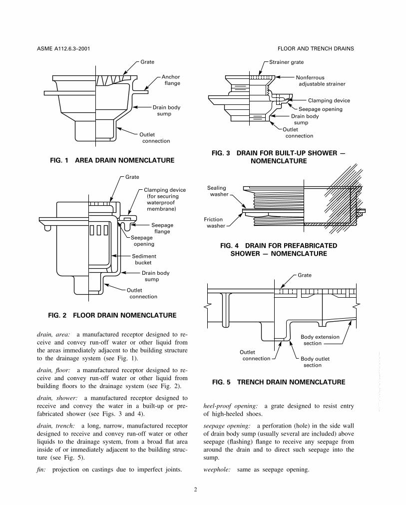
Grate
Anchor flange
Drain body sump
Outlet connection
FIG. 1 AREA DRAIN NOMENCLATURE
Grate
Clamping device (for securing waterproof membrane)
Seepage flange
Seepage opening
Sediment bucket
Drain body sump
Outlet connection
FIG. 2 FLOOR DRAIN NOMENCLATURE
drain, area: a manufactured receptor designed to re-ceive and convey run-off water or other liquid fromthe areas immediately adjacent to the building structureto the drainage system (see Fig. 1).
drain, floor: a manufactured receptor designed to re-ceive and convey run-off water or other liquid frombuilding floors to the drainage system (see Fig. 2).
drain, shower: a manufactured receptor designed toreceive and convey the water in a built-up or pre-fabricated shower (see Figs. 3 and 4).
drain, trench: a long, narrow, manufactured receptordesigned to receive and convey run-off water or otherliquids to the drainage system, from a broad flat areainside of or immediately adjacent to the building struc-ture (see Fig. 5).
fin: projection on castings due to imperfect joints.
2
Strainer grate
Seepage opening
Clamping device
Drain body sump
Outlet connection
Nonferrous adjustable strainer
FIG. 3 DRAIN FOR BUILT-UP SHOWER —
NOMENCLATURE
Sealing washer
Friction washer
FIG. 4 DRAIN FOR PREFABRICATED
SHOWER — NOMENCLATURE
Body outlet section
Body extension section
Outlet connection
Grate
FIG. 5 TRENCH DRAIN NOMENCLATURE
heel-proof opening: a grate designed to resist entryof high-heeled shoes.
seepage opening: a perforation (hole) in the side wallof drain body sump (usually several are included) aboveseepage (flashing) flange to receive any seepage fromaround the drain and to direct such seepage into thesump.
weephole: same as seepage opening.
Copyright ASME International Provided by IHS under license with ASME Licensee=Hong Kong Polytechnic Univ/9976803100
Not for Resale, 07/23/2009 18:23:41 MDTNo reproduction or networking permitted without license from IHS
--`,`````,``,`,`,,,,``,,`,`,,,,,-`-`,,`,,`,`,,`---
FLOOR AND TRENCH DRAINS ASME A112.6.3–2001
2 GENERAL REQUIREMENTS
2.1 Drain Bodies
2.1.1 Materials. Drain bodies shall be of cast iron,copper alloy, ABS, PVC, PE, PP, or other approvedmaterials meeting the requirements of this Standard.Materials shall comply with the standards cited in para.1.4. No obstruction shall be permitted in the caulkingarea of a body.
2.1.2 Weep Holes. Weep holes in bodies shall bea minimum of three in number and shall be a minimumof 0.125 in. (3.2 mm) in diameter.
2.1.3 Smooth Mating Surfaces. The body andclamping ring shall have smooth, level surfaces toprovide a watertight joint with the membrane.
2.2 Shower Drains
2.2.1 Strainers. Shower drain strainers shall bestainless steel 300 series alloy with a minimum thicknessof 0.050 in. (1.3 mm). The strainer shall be of thesnap-on type or screw fastened. The minimum waterwayarea of strainers shall be equal to the area of a 2 in.pipe [3.1416 in.2 (2 027 mm2 )].
2.2.2 Crown/Collar. A 24 gauge corrosion-resis-tant crown and/or collar of 1⁄4 in. brass ring shall berequired between the strainer and cast iron bodies.
2.3 Bolts and Fasteners
Bolts and fasteners for cast iron or copper alloydrains shall be a minimum of 5⁄16 in. NC. Bolts andfasteners for plastic drains shall be a minimum of 1⁄4in. NC. A minimum of three bolts per drain shall beprovided. Screw and bolts provided for shower drainsshall be 300 series stainless steel or copper alloycomplying with ASTM B 584 (Alloy C 85200 or C85400) or ASTM B 16.
3 OUTLETS — TYPES AND CONNECTIONS
3.1 Outlet Types
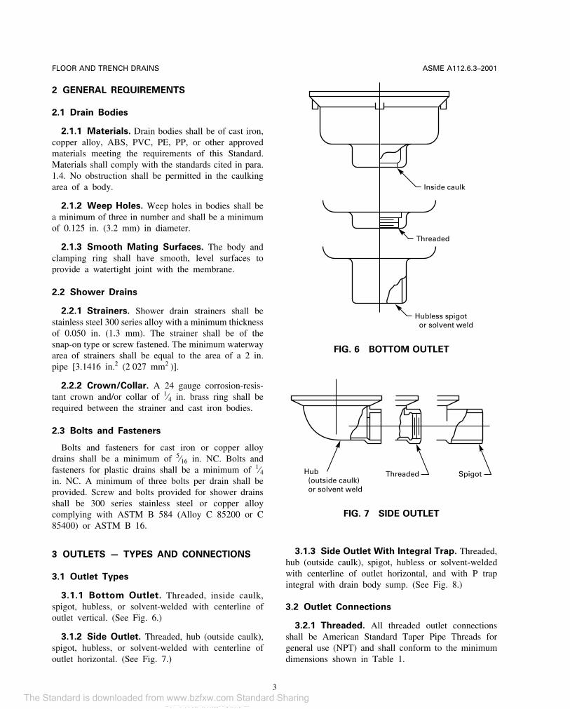
3.1.1 Bottom Outlet. Threaded, inside caulk,spigot, hubless, or solvent-welded with centerline ofoutlet vertical. (See Fig. 6.)
3.1.2 Side Outlet. Threaded, hub (outside caulk),spigot, hubless, or solvent-welded with centerline ofoutlet horizontal. (See Fig. 7.)
3
Inside caulk
Threaded
Hubless spigot or solvent weld
FIG. 6 BOTTOM OUTLET
SpigotThreadedHub (outside caulk) or solvent weld
FIG. 7 SIDE OUTLET
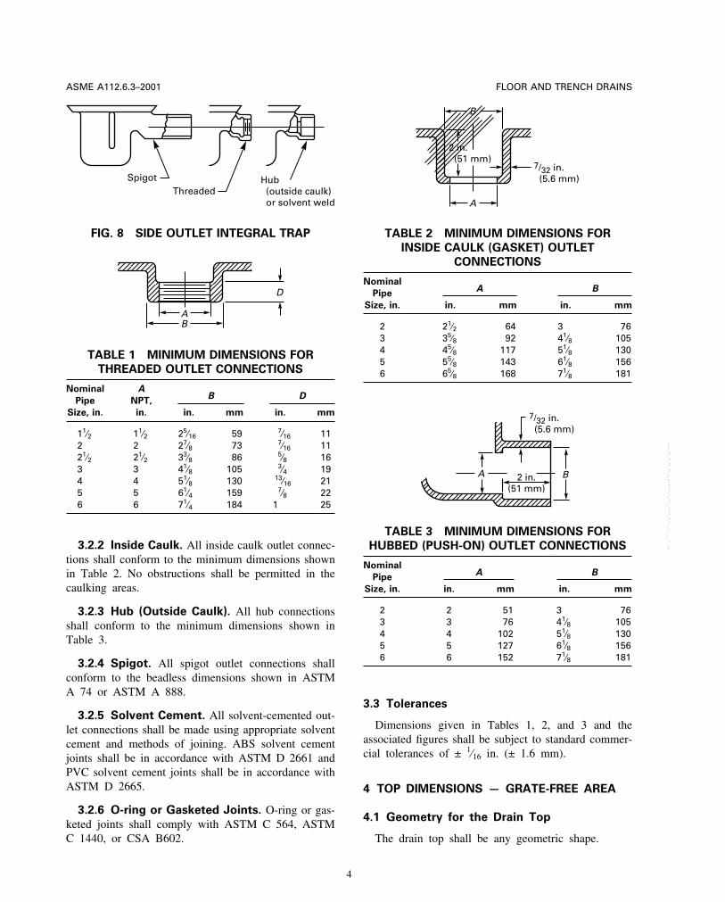
3.1.3 Side Outlet With Integral Trap. Threaded,hub (outside caulk), spigot, hubless or solvent-weldedwith centerline of outlet horizontal, and with P trapintegral with drain body sump. (See Fig. 8.)
3.2 Outlet Connections
3.2.1 Threaded. All threaded outlet connectionsshall be American Standard Taper Pipe Threads forgeneral use (NPT) and shall conform to the minimumdimensions shown in Table 1.
Copyright ASME International Provided by IHS under license with ASME Licensee=Hong Kong Polytechnic Univ/9976803100
Not for Resale, 07/23/2009 18:23:41 MDTNo reproduction or networking permitted without license from IHS
--`,`````,``,`,`,,,,``,,`,`,,,,,-`-`,,`,,`,`,,`---
The Standard is downloaded from www.bzfxw.com Standard Sharing
FLOOR AND TRENCH DRAINSASME A112.6.3–2001
SpigotThreaded
Hub (outside caulk) or solvent weld
FIG. 8 SIDE OUTLET INTEGRAL TRAP
BA
D
TABLE 1 MINIMUM DIMENSIONS FOR
THREADED OUTLET CONNECTIONS
Nominal AB D
Pipe NPT,
Size, in. in. in. mm in. mm
11⁄2 11⁄2 25⁄16 59 7⁄16 112 2 27⁄8 73 7⁄16 1121⁄2 21⁄2 33⁄8 86 5⁄8 163 3 41⁄8 105 3⁄4 194 4 51⁄8 130 13⁄16 215 5 61⁄4 159 7⁄8 226 6 71⁄4 184 1 25
3.2.2 Inside Caulk. All inside caulk outlet connec-tions shall conform to the minimum dimensions shownin Table 2. No obstructions shall be permitted in thecaulking areas.
3.2.3 Hub (Outside Caulk). All hub connectionsshall conform to the minimum dimensions shown inTable 3.
3.2.4 Spigot. All spigot outlet connections shallconform to the beadless dimensions shown in ASTMA 74 or ASTM A 888.
3.2.5 Solvent Cement. All solvent-cemented out-let connections shall be made using appropriate solventcement and methods of joining. ABS solvent cementjoints shall be in accordance with ASTM D 2661 andPVC solvent cement joints shall be in accordance withASTM D 2665.
3.2.6 O-ring or Gasketed Joints. O-ring or gas-keted joints shall comply with ASTM C 564, ASTMC 1440, or CSA B602.
4
B
A
7/32 in. (5.6 mm)
2 in. (51 mm)
TABLE 2 MINIMUM DIMENSIONS FOR
INSIDE CAULK (GASKET) OUTLET
CONNECTIONS
NominalA B
Pipe
Size, in. in. mm in. mm
2 21⁄2 64 3 763 35⁄8 92 41⁄8 1054 45⁄8 117 51⁄8 1305 55⁄8 143 61⁄8 1566 65⁄8 168 71⁄8 181
B2 in.(51 mm)
7/32 in. (5.6 mm)
A
TABLE 3 MINIMUM DIMENSIONS FOR
HUBBED (PUSH-ON) OUTLET CONNECTIONS
NominalA B
Pipe
Size, in. in. mm in. mm
2 2 51 3 763 3 76 41⁄8 1054 4 102 51⁄8 1305 5 127 61⁄8 1566 6 152 71⁄8 181
3.3 Tolerances
Dimensions given in Tables 1, 2, and 3 and theassociated figures shall be subject to standard commer-cial tolerances of ± 1⁄16 in. (± 1.6 mm).
4 TOP DIMENSIONS — GRATE-FREE AREA
4.1 Geometry for the Drain Top
The drain top shall be any geometric shape.
Copyright ASME International Provided by IHS under license with ASME Licensee=Hong Kong Polytechnic Univ/9976803100
Not for Resale, 07/23/2009 18:23:41 MDTNo reproduction or networking permitted without license from IHS
--`,`````,``,`,`,,,,``,,`,`,,,,,-`-`,,`,,`,`,,`---
FLOOR AND TRENCH DRAINS ASME A112.6.3–2001
TABLE 4 OPEN AREA REQUIREMENTS
FOR DRAINS
TransverseOutlet
Area of Grate Free AreaConnection
Connecting Pipe Min.Size,
in. in.2 cm2 in.2 cm2
Floor Drains
2 3.14 20.3 5.0 32.33 7.06 45.5 11.0 71.04 12.5 80.6 18.0 116.15 19.6 126.4 30.0 193.56 28.3 182.5 42.0 270.9
Shower Drains
2 3.14 20.3 5.0 32.33 7.06 45.5 11.0 71.04 12.5 80.6 18.0 116.1
Area and Trench Drains (subject to rainfall)
2 3.14 20.3 6.5 41.93 7.06 45.5 14.0 90.34 12.5 80.6 25.0 161.35 19.6 126.4 40.0 258.06 28.3 182.5 56.0 361.2
4.2 Open Area Requirements for Various
Classifications of Drains
Opening area requirements for drains shall be asshown in Table 4.
4.3 Openings in Top Grates
Openings shall be any geometric shape. Openingsshall be sized to exclude debris and accommodate theanticipated traffic. When drainage requirements dictateopenings that would permit entrance of debris, a sedi-ment bucket shall be installed in the drain body sumpto intercept this debris.
5 TOP LOADING — CLASSIFICATION
5.1 Loading Classifications
Grates and top rims shall be designed to meet thefollowing loading classifications:
5.1.1 Light Duty. Grates having safe live load (ascalculated in para. 5.2.5) under 2,000 lb (900 kg).
5.1.2 Medium Duty. Grates having safe live load(as calculated in para. 5.2.5) between 2,000 lb (900kg) and 4,999 lb (2 250 kg).
5
5.1.3 Heavy Duty. Grates having safe live load(as calculated in para. 5.2.5) between 5,000 lb (2 250kg) and 7,499 lb (3 375 kg).
5.1.4 Extra Heavy Duty. Grates having safe liveload (as calculated in para. 5.2.5) between 7,500 lb(3 375 kg) and 10,000 lb (4 500 kg).
5.1.5 Special Duty. Grates having safe live load(as calculated in para. 5.2.5) over 10,000 lb (4 500 kg)shall be considered special duty.
5.2 Test Procedure for Grate Loading
Safe live load requirements, as listed in para. 5.1shall be determined as follows:
5.2.1 Load Classifications. Load classificationsas stated in para. 5.1 shall be determined by labora-tory tests.
5.2.2 Platen Size. A 3.5 in. (89 mm) diameterplaten shall be applied to the center of the gratespecimen.
5.2.3 Loading. Loading shall be applied slowly sothat point of failure can be observed.
5.2.4 Point of Failure
(a) Brittle Materials (Cast Iron). The point of failureof brittle materials shall be the load (in pounds orkilograms) at which the first fracture on any part ofthe specimen appears.
(b) Ductile Material. The point of failure of ductilematerials shall be the load at which the permanent set(at the point of loading) is greater than 2% of thelongest transverse dimension of the specimen.
5.2.5 Safe Live Load. The maximum safe liveload shall be computed by dividing the load at failureby two.
6 MATERIALS AND FINISHES
6.1 Materials
The items covered in this Standard shall be ofthe material specified and shall meet all applicablerequirements and standards given herein. The castingsfor these drains shall be sound, free of blow holes,cold shuts, and other imperfections, and shall be ofuniform wall thickness and true to pattern. They shallalso be clean and free of fins. It shall not be the intentof this Standard to limit acceptable materials to thoseincluded in this section. The use of other materials
Copyright ASME International Provided by IHS under license with ASME Licensee=Hong Kong Polytechnic Univ/9976803100
Not for Resale, 07/23/2009 18:23:41 MDTNo reproduction or networking permitted without license from IHS
--`,`````,``,`,`,,,,``,,`,`,,,,,-`-`,,`,,`,`,,`---
The Standard is downloaded from www.bzfxw.com Standard Sharing
FLOOR AND TRENCH DRAINSASME A112.6.3–2001
meeting the requirements of this Standard and havingcomparable performance shall be permitted.
6.1.1 Cast Iron. Castings shall conform to ASTMSpecification for Grey Iron Castings A 48, Class 25.The minimum thickness for the casting shall be 7⁄32
in. (5.6 mm).
6.1.2 Copper Alloy. Castings shall conform to thechemical and mechanical requirements of ASTM B584 for Copper Alloy Nos. C83600, C83800, andC84400. The minimum thickness for the casting shallbe 5⁄32 in. (4 mm).
6.1.3 Leaded Nickel Bronze (Nickel Silver).
Castings shall conform to the chemical and mechanicalrequirements of ASTM B 584 for Copper Alloy Nos.C97300, C97600, and C99700. The minimum thicknessfor the casting shall be 5⁄32 in. (4 mm).
6.1.4 ABS. Floor drain bodies manufactured fromAcrylonitrile-Butadiene-Styrene (ABS) shall conform tophysical property requirements contained in ASTM D3965. The cell classification shall be 3-2-2-2-2. Theminimum thickness for the mold shall be 5⁄32 in. (4mm). Inserts for fasteners in plastic drains shall bemolded into the plastic material.
6.1.5 PVC. Floor drain bodies manufactured fromPoly (Vinyl Chloride) (PVC) shall conform to physicalproperty requirements contained in ASTM D1784. Thecell classification shall be 12454-B, 12454-C, or14333-C. The minimum thickness for the mold shallbe 5⁄32 in. (4 mm). Inserts for fasteners in plastic drainsshall be molded into the plastic material.
6.1.6 Bolting Materials. The materials for studs,nuts, cap screws, and other steel fasteners shall at leastequal the requirements of ASTM Specifications A 307,Carbon Steel Externally Threaded Fasteners, Grade A,and A 563, Carbon and Alloy Steel Nuts, Grade A.Threads shall be Classes 2A and 2B, and shall be plated.
6.2 Finishes
In all cases in which parts are to be coated or plated,they shall be cleaned to provide a suitable surface forproper bonding of the finish.
6.2.1 Paint Coatings. Iron castings shall becleaned and coated with a suitable paint, lacquer, orsynthetic coating of quality to provide protection againstrusting of ferrous surfaces during normal handling andwarehousing prior to installation.
6
6.2.2 Cadmium Plate. After preplating cleaning,parts shall be given a Commercial Grade CadmiumPlate.
6.2.3 Chrome Plate, Decorative. Parts shall bepolished prior to plating and then given a CommercialGrade Copper-Nickel-Chromium Plate.
6.2.4 Bronze Chromate. Parts shall first be givena Commercial Grade Cadmium Plate and then a Com-mercial Grade Bronze Chromate treatment.
6.2.5 Zinc Plate. After preplating cleaning, partsshall be given a Commercial Grade Zinc Plate.
7 VARIATIONS
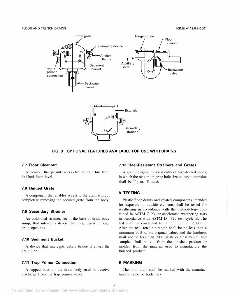
The optional features listed are stated here to identifythe variations available for different applications. (Seealso Fig. 9.)
7.1 Extension
A component that is used to raise the grate to thefloor level where deeper slabs are encountered.
7.2 Anchor Flange
A flange that extends from the side of drain bodyto enable anchoring of the drain to the concrete slab.
7.3 Auxiliary Inlet
A connection in the side of drain body sump thatreceives discharge from another fixture, appliance, ordrain.
7.4 Backwater Valve
A component that is used to prevent backflow ofwaste or storm water into the building.
7.5 Clamping Device
This component is installed in floors where a water-proof membrane, or metallic or composition flashingis required. The clamping device shall be a securednonpunctuating type of ring.
7.6 Dome Grate
A convex grate that has available grate-free areaabove floor level to enable drainage if debris collectsaround the base of the grate.
Copyright ASME International Provided by IHS under license with ASME Licensee=Hong Kong Polytechnic Univ/9976803100
Not for Resale, 07/23/2009 18:23:41 MDTNo reproduction or networking permitted without license from IHS
--`,`````,``,`,`,,,,``,,`,`,,,,,-`-`,,`,,`,`,,`---
FLOOR AND TRENCH DRAINS ASME A112.6.3–2001
Dome grate
Clamping device
Anchor flange
Sediment bucket
Backwater valve
Trap primer connection
Extension
Secondary strainer
Hinged grate
Auxillary inlet
Floor cleanout
Backwater valve
FIG. 9 OPTIONAL FEATURES AVAILABLE FOR USE WITH DRAINS
7.7 Floor Cleanout
A cleanout that permits access to the drain line fromfinished floor level.
7.8 Hinged Grate
A component that enables access to the drain withoutcompletely removing the secured grate from the body.
7.9 Secondary Strainer
An additional strainer, set in the base of drain bodysump, that intercepts debris that might pass throughgrate openings.
7.10 Sediment Bucket
A device that intercepts debris before it enters thedrain line.
7.11 Trap Primer Connection
A tapped boss on the drain body used to receivedischarge from the trap primer valve.
7
7.12 Heel-Resistant Strainers and Grates
A grate designed to resist entry of high-heeled shoes,in which the maximum grate hole size in least dimensionshall be 5⁄16 in. (8 mm).
8 TESTING
Plastic floor drains and related components intendedfor exposure to outside elements shall be tested forweathering in accordance with the methodology con-tained in ASTM G 23, or accelerated weathering testsin accordance with ASTM D 4329 test cycle B. Thetest shall be conducted for a minimum of 2,000 hr.After the test, tensile strength shall be no less than aminimum 90% of its original value; and the hardnessshall not be less than 20% of its original value. Testsamples shall be cut from the finished product ormolded from the material used to manufacture thefinished product.
9 MARKING
The floor drain shall be marked with the manufac-turer’s name or trademark.
Copyright ASME International Provided by IHS under license with ASME Licensee=Hong Kong Polytechnic Univ/9976803100
Not for Resale, 07/23/2009 18:23:41 MDTNo reproduction or networking permitted without license from IHS
--`,`````,``,`,`,,,,``,,`,`,,,,,-`-`,,`,,`,`,,`---
The Standard is downloaded from www.bzfxw.com Standard Sharing
ASME STANDARDS RELATED TO PLUMBING
Air Gaps in Plumbing Systems. . . . . . . . . . . . . . . . . . . . . . . . . . . . . . . . . . . . . . . . . . . . . . . . A112.1.2-1991(R1998)Air Gap Fittings for Use With Plumbing Fixtures, Appliances, and
Appurtenances . . . . . . . . . . . . . . . . . . . . . . . . . . . . . . . . . . . . . . . . . . . . . . . . . . . . . . . . . . . . . . . . . . . . .A112.1.3-2000Performance Standard and Installation Procedures for Stainless Steel
Drainage Systems for Sanitary, Storm, and Chemical Applications,Above and Below Ground . . . . . . . . . . . . . . . . . . . . . . . . . . . . . . . . . . . . . . . . . . . . . . . . . . . . . . . . . .A112.3.1-1993
Macerating Toilet Systems and Related Components . . . . . . . . . . . . . . . . . . . . . . . . . . . . . . . . . .A112.3.4-2000Water Heater Relief Valve Drain Tubes . . . . . . . . . . . . . . . . . . . . . . . . . . . . . . . . . . . . . . . . A112.4.1-1993(R1998)Plastic Fittings for Connecting Water Closets to the
Sanitary Drainage System . . . . . . . . . . . . . . . . . . . . . . . . . . . . . . . . . . . . . . . . . . . . . . . . . . . . . . . . . .A112.4.3-1999Floor-Affixed Supports for Off-the-Floor Plumbing Fixtures for
Public Use. . . . . . . . . . . . . . . . . . . . . . . . . . . . . . . . . . . . . . . . . . . . . . . . . . . . . . . . . . . . . . . . . . . . . . . .A112.6.1M-1997Framing-Affixed Supports for Off-the-Floor Water Closets With
Concealed Tanks . . . . . . . . . . . . . . . . . . . . . . . . . . . . . . . . . . . . . . . . . . . . . . . . . . . . . . . . . . . . . . . . . . .A112.6.2-2000Enameled and Epoxy Coated Cast Iron and PVC Plastic Sanitary
Floor Sinks . . . . . . . . . . . . . . . . . . . . . . . . . . . . . . . . . . . . . . . . . . . . . . . . . . . . . . . . . . . . . . . . . . . . . . . . .A112.6.7-2001Backwater Valves . . . . . . . . . . . . . . . . . . . . . . . . . . . . . . . . . . . . . . . . . . . . . . . . . . . . . . . . . . . . A112.14.1-1975(R1998)Grease Interceptors . . . . . . . . . . . . . . . . . . . . . . . . . . . . . . . . . . . . . . . . . . . . . . . . . . . . . . . . . . . . . . . . . A112.14.3-2000Grease Removal Devices. . . . . . . . . . . . . . . . . . . . . . . . . . . . . . . . . . . . . . . . . . . . . . . . . . . . . . . . . . . . . .A112.4.4-2001Plumbing Fixture Fittings . . . . . . . . . . . . . . . . . . . . . . . . . . . . . . . . . . . . . . . . . . . . . . . . . . . . . . . . . . . A112.18.1-2000Performance Requirements for Backflow Protection Devices
and Systems in Plumbing Fixture Fittings . . . . . . . . . . . . . . . . . . . . . . . . . . . . . . . . . . . . . . . .A112.18.3M-1996Flexible Water Connectors . . . . . . . . . . . . . . . . . . . . . . . . . . . . . . . . . . . . . . . . . . . . . . . . . . . . . . . . . . A112.18.6-1999Deck-Mounted Bath/Shower Transfer Valves With Integral
Backflow Protection . . . . . . . . . . . . . . . . . . . . . . . . . . . . . . . . . . . . . . . . . . . . . . . . . . . . . . . . . . . . . . A112.18.7-1999Enameled Cast Iron Plumbing Fixtures . . . . . . . . . . . . . . . . . . . . . . . . . . . . . . . . . . . . . A112.19.1M-1994(R1999)Vitreous China Plumbing Fixtures . . . . . . . . . . . . . . . . . . . . . . . . . . . . . . . . . . . . . . . . . . . . . . . . . .A112.19.2M-1998Stainless Steel Plumbing Fixtures (Designed for Residential Use) . . . . . . . . . . . . . . . . . . . . A112.19.3-2000Porcelain Enameled Formed Steel Plumbing Fixtures. . . . . . . . . . . . . . . . . . . . . . . A112.19.4M-1994(R1999)Trim for Water-Closet Bowls, Tanks, and Urinals . . . . . . . . . . . . . . . . . . . . . . . . . . . . . . . . . . . . A112.19.5-1999Hydraulic Performance Requirements for Water Closets and Urinals . . . . . . . . . . . . . . . . . A112.19.6-1995Whirlpool Bathtub Appliances . . . . . . . . . . . . . . . . . . . . . . . . . . . . . . . . . . . . . . . . . . . . . . . . . . . . .A112.19.7M-1995Suction Fittings for Use in Swimming Pools, Wading Pools, Spas,
Hot Tubs, and Whirlpool Bathtub Appliances. . . . . . . . . . . . . . . . . . . . . . . . . . . . . A112.19.8M-1987(R1996)Non-Vitreous Ceramic Plumbing Fixtures. . . . . . . . . . . . . . . . . . . . . . . . . . . . . . . . . . . A112.19.9M-1991(R1998)Dual Flush Devices for Water Closets . . . . . . . . . . . . . . . . . . . . . . . . . . . . . . . . . . . . . . . . . . . . . . A112.19.10-1994Wall Mounted and Pedestal Mounted, Adjustable and Pivoting
Lavatory and Sink Carrier Systems. . . . . . . . . . . . . . . . . . . . . . . . . . . . . . . . . . . . . . . . . . . . . . . A112.19.12-2000Bathtub/Whirlpool Bathtubs With Pressure Sealed Doors . . . . . . . . . . . . . . . . . . . . . . . . . . . A112.19.15-2001Floor Drains . . . . . . . . . . . . . . . . . . . . . . . . . . . . . . . . . . . . . . . . . . . . . . . . . . . . . . . . . . . . . . . A112.21.1M-1991(R1998)Roof Drains. . . . . . . . . . . . . . . . . . . . . . . . . . . . . . . . . . . . . . . . . . . . . . . . . . . . . . . . . . . . . . . . . . . . . . . .A112.21.2M-1983Hydrants for Utility and Maintenance Use . . . . . . . . . . . . . . . . . . . . . . . . . . . . . . . . . . A112.21.3M-1985(R1995)Cleanouts . . . . . . . . . . . . . . . . . . . . . . . . . . . . . . . . . . . . . . . . . . . . . . . . . . . . . . . . . . . . . . . . . A112.36.2M-1991(R1998)
The ASME Publications Catalog shows a complete list of all the Standards published by the Society.For a complimentary catalog, or the latest information about our publications, call 1-800-THE-ASME(1-800-843-2763).
Copyright ASME International Provided by IHS under license with ASME Licensee=Hong Kong Polytechnic Univ/9976803100
Not for Resale, 07/23/2009 18:23:41 MDTNo reproduction or networking permitted without license from IHS
--`,`````,``,`,`,,,,``,,`,`,,,,,-`-`,,`,,`,`,,`---
J04001
Copyright ASME International Provided by IHS under license with ASME Licensee=Hong Kong Polytechnic Univ/9976803100
Not for Resale, 07/23/2009 18:23:41 MDTNo reproduction or networking permitted without license from IHS
--`,`````,``,`,`,,,,``,,`,`,,,,,-`-`,,`,,`,`,,`---The Standard is downloaded from www.bzfxw.com Standard Sharing