Embed Size (px)
Citation preview
Florida State University
Telecommunications Infrastructure Standard
SPECIAL EDITION FOR ARCHITECT AND ENGINEERING DESIGN
Revision 2.2g
May 22, 2006
FSU Design Guidelines Specifications, Appendex A
Document developed by:
Office of Telecommunications Operations Division
2
REVISION HISTORY ..........3 INTRODUCTION ……..6 I. CONDUIT AND MANHOLE SYSTEM ..........8
A. SERVICE ENTRANCE ..........8 B. MANHOLES ........10 C. OUTSIDE PLANT CONDUIT (INTER BUILDING) ........10 D. HORIZONTAL PATHWAY DISTRIBUTION SYSTEMS (INTRA
BUILDING) ..…..12 E. MISCELLANEOUS DISTRIBUTION SYSTEMS ……16 F. INTRABUILDING BACKBONE RISER CONDUIT SYSTEM ……16
II. TELECOMMUNICATIONS ROOMS / EQUIPMENT ROOMS ........18
A. DEFINITION ……18 B. REQUIREMENTS ……19
III. TELECOMMUNICATIONS GROUNDING AND BONDING ……28 IV. OTHER ........28
A. CAMPUS MASTER PLAN ........29 B. INSPECTION AND TESTING INSTALLATION ........29 C. COIN OPERATED TELEPHONES ........29 D. BLUE LIGHT EMERGENCY TELEPHONES ........29 E. ELEVATOR PHONES ........29 F. WIRELESS APPLICATIONS ........29
V. APPLICABLE CODES AND STANDARDS ……30 VI. GLOSSARY OF TERMS ……31 VII. ILLUSTRATIONS ……38
A. FIG 1 – RISER CONDUIT LAYOUT ……39 B. FIG 2 – TYPICAL BACKBOARD LAYOUT ……40 C. FIG 3 – TYPICAL TELECOMMUNICATIONS ROOM ……41 D. FIG 4 – ELEVATOR TELEPHONE TEMPLATE ……42
Questions or comments concerning this document should be directed to: Larry E. Downing, RCDD Manager, Technology and Infrastructure Florida State University Office of Telecommunications Engineering Group 902 Wildwood Ave. Tallahassee, Florida 32306-1120
2
REVISION HISTORY Subsequent modifications are listed below: URev Date Change 1.0 6/17/93 -Document created at request of the Physical Plant Department to assist A
/ E professionals. 1 (a) 10/25/93 -Deeper boxes at the termination end of conduit runs. 2 ½” deep. -Clarify that no obstructions shall go through ceiling raceways. -Clarify that no janitor rooms shall be placed in IDF or MDF rooms. -Clarify that ceiling raceway shall be used in conjunction with conduits
stubbed above the ceiling and ran back to the ceiling raceway / cable tray. -Conduits run in slabs or other concrete structures shall be PVC Schedule
40. 2.0 2/1/00 -Major Revision.
• Addition of underground entrance conduit recommendations. • Addition of spare conduit to requirement for recommended entrance
conduit counts. • Added references to building entrance buried and aerial cable section. • Added manhole interior hardware list. • Added concrete strength for manholes – 3500 psi. • Added outside plant conduit ductbank requirements. • Added special outside plant applications. • Added recommended design guidelines to horizontal pathway
/conduit. • Added design guidelines to horizontal pathway / cable tray. • Added elevator conduit requirements to horizontal pathway special
consideration section. • Added ADA requirements to horizontal pathway special consideration
section. • Changed Vertical Riser section to Intrabuilding backbone Riser
Conduit System. • Added location, height and installation recommendations for riser
sleeves to riser conduit design section. • Changed section II from Equip rooms to telecom rooms and equip
rooms. • Changed name of main telecom room from MDF to MTC. • Changed name of telecom rooms from IDF to TC. • Added serving floor space recommendations for TC’s. • Added restrictions on other utilities and services sharing MTC and
TC’s.
Revision 2.2d Office of Telecommunications Florida State University WWW.OTC.FSU.EDU
4
• Changed wall coverage of plywood in MTC and TC to include all walls.
• Added installation requirements of plywood on walls in MTC and TC. • Added lighting requirement section for MTC and TC. • Added power requirements section for MTC and TC. • Added room size recommendation section for MTC and TC. • Added work clearance section for MTC and TC. • Added RFI/EMI section for MTC and TC. • Added pathway installation section for MTC and TC. • Added ceiling section for MTC and TC. • Added location section for MTC and TC. • Changed door height and optional lock-box to entry section for MTC
and TC. • Added vertical stacking of rooms and conduit/sleeve recommended
layout for MTC TC rooms. • Added Fire Protection section to MTC and TC. • Added environmental control section to MTC and TC. • Added wall lining section to CPE rooms. • Added lighting section to CPE rooms. • Added power section to CPE rooms. • Added rooms size section to CPE rooms. • Added RFI/EMI section to CPE rooms. • Added pathway section to CPE rooms. • Added ceiling section to CPE rooms. • Added locations section to CPE rooms. • Added entry section to CPE rooms. • Added conduit alignment to room layout of CPE rooms. • Added fire protection section to CPE rooms. • Added environmental section to CPE rooms. • Added depth and plywood requirement for inside of terminal boxes. • Added lighting section to CPE rooms. • Added Powere section to CPE rooms. • Added grounding section to CPE rooms. • Added configuration of conduits to CPE room section. • Added grounding and bonding section. • Added Codes and Standards section. • Added Glossary of terms. • Added Illustrations section.
2.1 7/25/00
• Added 4”W x 16”L x 3”D (Raco 956 or Equiv) to Horizontal pathway Horizontal pathway sect. 1 a. 9
• Added flush cover to 4”x4” wall box (Raco 787 or Equiv) Horizontal pathway sect. 1 a. 10
Revision 2.2d Office of Telecommunications Florida State University WWW.OTC.FSU.EDU
5
• Changed wall box for pay telephones, wall phones etc to 4”x4”. Horizontal pathway sect. 1 a. 11
• Added B/C grade plywood as an option for backboard material. • Added Card security / card swipe conduit requirement. I.D.2.f
2.1 10/18/00 - Added minimum size opening for access panels below pull boxes in
hardcoat ceilings. D.1.a.9
2.1 02/21/01 - Change to define entrance conduit requirements. A total of 2w4 (2-4") conduits as a minimum into any building under 10,000 square ft usable floor space. Conduit duct banks entering buildings of over 10,000 square feet shall be sized with the assistance of the Office of Telecommunications.
2.2 03/30/01 - Changes made to various areas to clarify conduit installation design
criteria including attachment to walls, turning down of conduits to TBB, floor height, etc. To eliminate confusion the term closet has been replaced with room.
2.2a 07/24/01 - Change Section I.B. MANHOLES from "round lids no less than 32
inches" to read "round lids with a diameter of 32 1/2 inches." 2.2a 08/22/01 - Change Section I.B. MANHOLES from " New manholes shall be 8'x8'x8'
deep octagon" to " New manholes shall be 8'x8'x7' deep octagon". 2.2b 8/24/02 - Addition to Section I.D.2.g “Floor Outlets – Floor outlets shall be
multiservice recessed floor boxes, Wiremold/Walker part number RFB4-SS with RFB-4TKO-SS internal communications brackets. Any equivalent box shall be approved in advance by the FSU Office of Telecommunications.”
2.2b 11/5/02 - Added specifications and restructured Horizontal Pathway Sections
D.1.b Secondary Design Choice - Ceiling Raceway and D.1.c.Third Design Choice – Zone Conduit.
2.2b 2/14/03 - Misc corrections. New description of clearances in Communications
rooms. 2.2c 7/8/03 - Sec I.D.1.a Horizontal Pathway, added specifications of catv conduit
to be ¾”. 2.2c 7/8/03 - Sec II.B Power, Added A/C outlet to be installed in each comm. Room
on end of Relay Rack. 2.2d 2/5/04 - Add description of Code Blue installation requirements. 2.2d 4/27/04 - I.D.2 Added Access / Security Door Raceway requirements
Revision 2.2d Office of Telecommunications Florida State University WWW.OTC.FSU.EDU
6
2.2e 8/3/04 - Added specification for inside Code Blue Emergency phones. 2.2e 9/30/04 - II.D.2 Added electrical specifications for Access systems. 2.2f 04/11/05 - Added Elevator telephone template – figure 4 2.2g 07/27/05 - Changed Sec II Telecom Rooms requirement for 2 – 4” conduits between
telecom rooms on same floor to 1 – 4” minimum. 2.2g 05/22/06 - Changed Emergency Blue Light Phones from Code Blue to Talk-A-
Phone
Revision 2.2d Office of Telecommunications Florida State University WWW.OTC.FSU.EDU
7
INTRODUCTION TO…. FSU’S TELECOMMUNICATIONS INFRASTRUCTURE STANDARD
The Office of Telecommunications (OTC) is proud to release the latest update to the FSU
Telecommunications Infrastructure Standard. Release2.2. A Telecommunications Infrastructure Standard for FSU has been in existence for over (13) years. During that time it has had over (16) revision. The OTC in conjunction with FSU's IMR Manager, Facilities Planning and Construction, Academic Computing & Networking Services, the Campus Networking Committee and Office of Technology Integration has evolved and developed the Florida State University Telecommunications Infrastructure Standard.
The mission of the Office of Telecommunications as clearly outlined in the Finance and Administration Business handbook is for the OTC to be the “University's coordinator and provider of telecommunications transport services on and off of campus. This includes, but is not limited to all infrastructure of copper, coax and fiber wiring within and between campus, calling features, CATV, consulting and operator services, local dial tone, directed moves, emergency telephones, frequency coordination, outside plant, pay telephones, telephone instrumentation, voice and video conferencing, wireless technologies, voice mail, long distance services, paging, security and access and 2-way radio.” Additionally, “The OTC has the responsibility of design, development, approval, installation, maintenance and management of telecommunications wiring and infrastructure in all FSU owned and leased buildings and properties. This would include but is not limited to voice, video and data infrastructure with fiber, copper or coaxial cabling. This also includes telecommunication rooms, raceways, conduit systems, duct banks and the campus telecommunications manhole system. Such responsibility implies a first right of refusal by the OTC on all wiring design, development, approval, installation, maintenance and management.”
The OTC works closely with many departments at FSU to assure that this mandate is carried out. We do this in two main ways.
a. The OTC in conjunction with Campus Design and Campus Planning review design
documents in several phases of completion to assure their compliance to local and national standards and codes. Typically design development, conceptual drawing, 50% and 100% drawing are all reviewed and input on changes are implemented throughout the process.
Revision 2.2d Office of Telecommunications Florida State University WWW.OTC.FSU.EDU
8
b. Working with design professionals, departments and electrical engineers they have ready access to this standard to reference when questions or conflicts should arise in any construction or renovation process. Through close interaction during the design of new projects, the review of renovation projects and future campus planning the entire design team assures that uniform, cost effective and high quality telecommunications infrastructure are consistently installed.
We are pleased to have this valuable tool available to you as you design telecommunications infrastructure here at FSU. Please feel free to contact or office when needs arise. Our goal is to be available to assist you at any time before or during the decision making process. Thank You I. CONDUIT AND MANHOLE SYSTEM
Revision 2.2d Office of Telecommunications Florida State University WWW.OTC.FSU.EDU
9
A. USERVICE ENTRANCE
The Service entrance is the route by which Telecommunication services/lines enter a building. There are three types of service entrances:
• Underground Entrance - buried conduit (FSU responsibility) • Buried Entrance - cable buried in a trench ( Service Provider responsibility) • Aerial Entrance - cable drop from a pole to a building. ( Service Provider
responsibility)
Service entrances shall terminate at the main telecommunications room / terminal room location of the building; usually on the ground floor or basement.
1. Underground Entrance – The following recommendations are made for underground entrances:
a. The recommended size for conduit used in an underground entrance is 4 inches in
diameter. A spare conduit of equal size is recommended, thus giving a total of 2w4 (2-4") conduits as a minimum into any building under 10,000 square ft usable floor space. Conduit duct banks entering buildings of over 10,000 square feet shall be sized with the assistance of the Office of Telecommunications.
b. Conduit must be buried at a minimum depth of no less than 36 inches (or to meet
local codes) and encased in concrete rated at 2,500 psi. For conduit that will be placed under a road use 3,500 psi rated concrete. Other special situations may require the use of stronger or a lighter 10 to 1 mixture. These exceptions shall be approved by the OTC design professional. To minimize any chance of accidental dig-up, place a plastic warning tape a minimum of 18 inches below the surface and directly above the conduit. Tape will be provided by the Office of Telecommunications on request. It is recommended that Telecommunications conduit not to be placed in joint trenches with other utilities. When this is necessary though, the design professional shall contact the Office of Telecommunications for design and coordination. Other utilities shall not be placed in telecommunications ducts. A # 6 AWG copper ground wire shall run parallel to the conduit within the concrete encasement. Design of underground entrance should be coordinated with the OTC. (UNOTEU: Telecommunications conduit shall not be poured and encased in the same concrete as the campus high voltage (typ.- 5kv-12kv) electrical conduits system. A minimum or 18” of fill shall be between the two facilities.)
c. Entrance conduit must not include more than two 90 degree bends without a pull
box, handhole or manhole. Bends must be sweeping bends with a radius not less than 10 times the inside diameter of the four inch conduit. NO LBs.
Revision 2.2d Office of Telecommunications Florida State University WWW.OTC.FSU.EDU
10
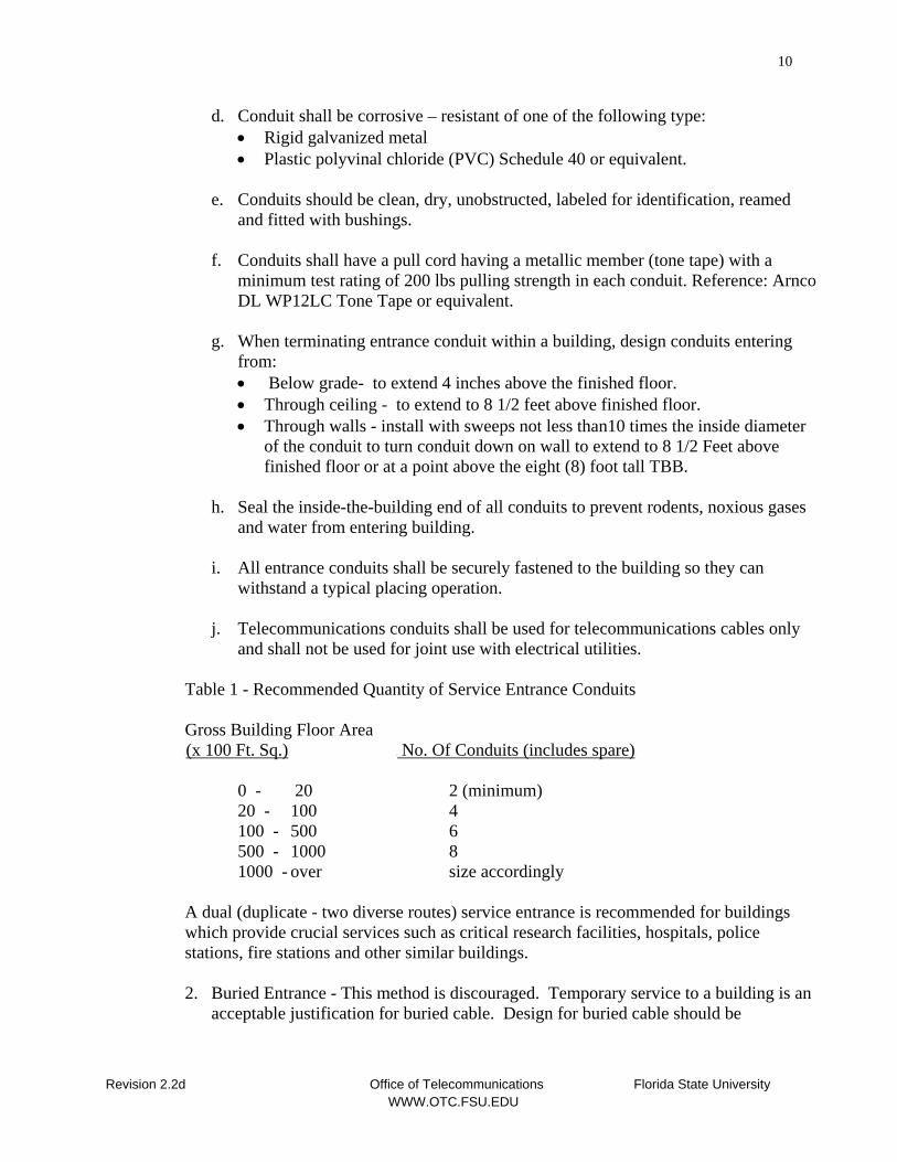
d. Conduit shall be corrosive – resistant of one of the following type: • Rigid galvanized metal • Plastic polyvinal chloride (PVC) Schedule 40 or equivalent.
e. Conduits should be clean, dry, unobstructed, labeled for identification, reamed
and fitted with bushings.
f. Conduits shall have a pull cord having a metallic member (tone tape) with a minimum test rating of 200 lbs pulling strength in each conduit. Reference: Arnco DL WP12LC Tone Tape or equivalent.
g. When terminating entrance conduit within a building, design conduits entering
from: • Below grade- to extend 4 inches above the finished floor. • Through ceiling - to extend to 8 1/2 feet above finished floor. • Through walls - install with sweeps not less than10 times the inside diameter
of the conduit to turn conduit down on wall to extend to 8 1/2 Feet above finished floor or at a point above the eight (8) foot tall TBB.
h. Seal the inside-the-building end of all conduits to prevent rodents, noxious gases
and water from entering building.
i. All entrance conduits shall be securely fastened to the building so they can withstand a typical placing operation.
j. Telecommunications conduits shall be used for telecommunications cables only
and shall not be used for joint use with electrical utilities. Table 1 - Recommended Quantity of Service Entrance Conduits Gross Building Floor Area U(x 100 Ft. Sq.)U U No. Of Conduits (includes spare)U
0 - 20 2 (minimum) 20 - 100 4 100 - 500 6 500 - 1000 8 1000 - over size accordingly A dual (duplicate - two diverse routes) service entrance is recommended for buildings
which provide crucial services such as critical research facilities, hospitals, police stations, fire stations and other similar buildings.
2. Buried Entrance - This method is discouraged. Temporary service to a building is an
acceptable justification for buried cable. Design for buried cable should be
Revision 2.2d Office of Telecommunications Florida State University WWW.OTC.FSU.EDU
11
coordinated with OTC. Refer to Section III, Media for additional information on buried cable.
3. Aerial Entrance - This method is discouraged. Temporary service to a building is an
acceptable justification or installation of cable into an existing facility when underground entrance is too expensive or would disturb vegetation. Pole sizes, clearances and cable sizes should allow for future growth and flexibility and meet. The installation of aerial cable entrance facilities and associated supporting structures should be coordinated with the OTC. Refer to Section III, Media for additional information on aerial cable.
Design professionals and contractors shall contact the OTC engineering group project manager for evaluation and determination of exceptions to design guidelines for entrance conduit.
B. UMANHOLESU
FSU has an extensive network of telecommunication manholes throughout campus. The facility design professional should assure all renovations and new construction projects connect to this system where needed. Any new manhole number assignment shall be coordinated through the OTC.
New manholes shall be 8'x8'x7' deep octagon with round lids with a diameter of 32 1/2 inches. Hand holes (small manholes) are not acceptable unless approved by the OTC. UNo square lids are permittedU. Lids should have pull-slots for easy removal, traffic rated, and labeled "TELECOMMUNICATIONS OR TELEPHONE. Grounding rods should be included in the design of all manholes. The distance between manholes shall be no more than 300 feet if a direct path is possible and no 90 degree bends are used. For every 90 degree bend used between manholes subtract 50 feet. No more than two 90 degree bends shall be installed between any two pulling points.
Manhole interior hardware must be galvanized. Manholes should be equipped with • Bonding inserts and struts for racking. • Pulling Eyes at least 7/8” in diameter. • A floor sump of at least 8” in diameter.
The strength of concrete used for manholes shall be at least 3,500 PSI.
C. UOUTSIDE PLANT CONDUIT (INTER-BUILDING DUCTBANKS)U
The University has a system of underground ductbanks throughout it’s property used for providing telecommunications services to University buildings. The use of conduit space in the Telecommunications Ductbanks shall be managed by the Office of Telecommunications.S
Revision 2.2d Office of Telecommunications Florida State University WWW.OTC.FSU.EDU
12
1. Outside Plant Conduit Duckbanks shall meet the following Requirements:
a. The recommended size for conduit used between manholes is 4 inches in diameter. Ductbanks connecting Manholes shall consist of a minimum of 8 (8) four inch (4”) conduits 8w4 (8-4").
b. Conduit must be buried at a minimum depth of 36 inches (or to meet local codes)
and encased in concrete rated at 2,500 psi. For conduit that will be placed under a road use 3,500 psi rated concrete. Other special situations may require the use of stronger or a lighter 10 to 1 mixture. These exceptions shall be approved by the OTC design professional. To minimize any chance of accidental dig-up, place a plastic warning tape a minimum of 18 inches below the surface and directly above the conduit. Tape will be provided by the Office of Telecommunications on request. It is recommended that Telecommunications conduit not to be placed in joint trenches with other utilities. When this is necessary though, the design professional shall contact the Office of Telecommunications for design and coordination. Other utilities shall not be placed in telecommunications ducts.
c. Do not include more than two 90 degree bends. Bends must be long sweeping
bends with a radius not less than 10 times the diameter of the four inch conduit. LB's Ushall notU be used.
d. Conduit shall be corrosive – resistant of one of the following type:
• Rigid galvanized metal • Plastic polyvinal chloride (PVC) Schedule 40 or equivalent.
e. A # 6 AWG copper ground wire shall run parallel to the conduit within the
concrete encasement. Design of underground entrance should be coordinated with the OTC. UNOTEU: Telecommunications conduit shall not be poured and encased in the same concrete as the campus high voltage (typical - 5kv-12kv) electrical conduits system. A minimum or 18” of fill shall be between the two facilities.
f. Conduits should be clean, dry, unobstructed, capped for protection, labeled for
identification reamed and fitted with bushings.
g. Provide a pull cord having a metallic member (tone tape) with a minimum test rating of 200 lbs pulling strength in each conduit. Reference: Arnco DL WP12LC Tone Tape or equivalent.
2. Special Outside Plant Applications-
a. Blue Light Emergency BLT towers Phones, Coin operated Pay-telephones, other
emergency and outside telephones – Emergency phones located outside require the following:
Revision 2.2d Office of Telecommunications Florida State University WWW.OTC.FSU.EDU
13
Provide 2” PVC schedule 40 conduit, buried a minimum of 30" with marker tape placed 18” below the surface and directly above the conduit. The conduit shall be terminated in the nearest manhole, building telephone equipment room or apparatus room. (closest service location). Conduit runs shall not exceed 200 feet without a handhole or pull box and shall contain no more than two 90 degree bends per 200 feet, excluding those bends within 5 feet of the pull box. A pullbox shall be provided within 10 feet of the BLT where the 2” conduit will terminate. A 1” conduit shall be installed from this point into the BLT. Conduit and pull boxes shall be for telecommunications cables only and not for joint use with electrical or other utilities. Install a nylon pull cord with a minimum test rating of 200lb pulling tension. Reference: Arnco DL WP12LC Tone Tape or equivalent.
b. Handholes / Pull-Boxes - Where handholes / pull boxes are used, they are not to be used for termination or splice boxes under any circumstances. Install handholes / pull-boxes in easily accessible locations, preferably not in parking or traffic areas. Installation should be at grade. Boxes should be provided with weather proof door/panel or cover arranged for access from the top. Avoid installation adjacent to sprinkler discharge. Conduits should be installed with sweeps. Do not use a pull-box in lieu of a bend. Telecom Pull boxes USHALL NOTU be used by other utilities.
D. UHORIZONTAL PATHWAY DISTRIBUTION SYSTEMS (INTRA BUILDING)
Telecommunication wiring distribution may be made through various ceiling distribution systems, especially where suspended ceilings are utilized.
1. UHORIZONTALU UCONDUIT DESIGN RECOMMENDATIONSU
a. UPreferred Design MethodU
Conduit System – Each workstation Voice / Data outlet box shall be installed using one (1”) inch conduit. CATV outlets shall be installed using three quarter (3/4”) inch conduit. All conduits shall be home-run or routed directly to the main telecommunications room (MTC) or telecommunications room (TC) of the same floor. (Physical Star Topology). Conduit shall be EMT with screw or compression fittings. UFlex conduit shall not be used in buildings for telecommunications cabling.U Horizontal conduits designated for outlets shall not feed floor to floor or be daisy chained from outlet to outlet.
Because the facilities conduit distribution system, once installed, is of "fixed capacity", it is often cost effective to install sufficient distribution conduits to accommodate potential changes and growth.
1) The total individual conduit length including pull boxes used for
telecommunications systems should not be longer than 250 feet.
Revision 2.2d Office of Telecommunications Florida State University WWW.OTC.FSU.EDU
14
2) Conduit runs should take the most direct path possible, following parallel lines
of the building.
3) There should be no conduit continuous sections longer than 100 feet. For sections that are longer than 100 feet, insert pull boxes so that no segment between pull boxes exceeds the 100 foot limit.
4) There should be no more than two 90 degree bends between pull boxes.
If a conduit run requires more than two 90 degree bends provide a pull box between sections with two bends or less or use the next larger size of conduit.
A third bend may be acceptable in a pull section without de-rating the conduit’s capacity if: - The run is not longer than 33 feet. - The conduit size is increased to the next trade size, or - One of the bends is located within 12 inches of the end of the cable feed
end. 5) Conduit bend radii shall be as specified in the current edition of the UNational
Electrical CodeU for conductors without lead sheath. Field and machine bent radii are acceptable.
6) Provide a pull cord with a minimum test rating of 200 lbs pulling strength in
each conduit. Greenlee Jetline, Part number 430 or equivalent.
7) Conduits should be clean, dry, unobstructed, labeled for identification, reamed and fitted with bushings.
8) Terminate conduits through the structural floor in the telecommunications
rooms three (3) inches above the floor surface. For conduits entering from the ceiling conduits should be installed to turn down and extend to 8 1/2 feet above finished floor in the Telecommunications rooms or equipment rooms. All conduits shall be dressed at the same level and installed with rigid conduit straps to the wall.
9) Pull-Boxes - Pull boxes shall be a minimum of 4”W x 16”L x 3”D D (Raco
956 or Equiv) for a single one (1) inch conduit. For each additional conduit two (2) inches should be added to the width of the box. Four (4) inch square outlet boxes Ushall notU be considered for pull-boxes under any circumstances. Pull Boxes are not to be used for termination or splice boxes under any circumstances. Install pull-boxes in easily accessible locations, preferably above suspended ceiling. In the case of hardcoat ceilings, an access panel shall be installed in the ceiling directly beneath any pull boxes. The opening shall be a minimum of 24" x 24" to allow for access. Pull Boxes should be provided
Revision 2.2d Office of Telecommunications Florida State University WWW.OTC.FSU.EDU
15
with a suitable hinged panel or cover arranged for access from the bottom. Conduits should be arranged to allow a straight pull through the box with no bends. Do not use a pull-box in lieu of a bend. Telecom Pull boxes shall not be used by other utilities.
NOTE: Designs that require pull boxes be mounted more than 10 feet above the floor shall first be approved by the OTC.
10) Telecommunications Workstation Outlet Boxes - All standard
telecommunications wall mounted workstation outlet boxes installed in dry wall, plaster or concrete block shall be four (4) inches square by at least 2 1/4” deep made by Steel City or equivalent. All boxes shall be trimmed out, allowing for a clear and unobstructed 4” opening. Provide all boxes with flush cover (Raco 787 or equiv). Boxes should be installed 15 inches above finished floor or the same height as electrical outlets at the workstation. Do not install outlet boxes back to back to serve adjacent rooms. Boxes should be offset to avoid compromise of the effectiveness of the sound barrier. Boxes shall not be installed and connected by the same 1” conduit in a daisy chain method or from floor to floor.
11) Outlet boxes for wall instruments, payphones and other special applications
shall be 4”W x 4”H x at least 2 1/4”D. These boxes should be mounted at 48” above the finished floor unless obstructed. Installation of outlets where obstructions exist shall meet all ADA requirements for clearance as specified below.
b. USecondary Design ChoiceU
Zoned Conduit System - Zoned conduit systems are recommended for areas with a high density of outlets such as computer labs or if space above a ceiling is not available or wall penetrations must be kept to a minimum. For office areas provide a minimum of one two-inch conduit for each 500 square feet of usable office area. Provide three one-inch outlet conduits for each two-inch conduit for telephone outlets within the zone. All two-inch zoned conduits shall be metallic and shall be run from the equipment room or satellite room to the zone where the conduit is terminated at a pull box. One-inch conduits shall also be terminated in the pull box. Sizing of conduits for high density areas such as computer labs must be individually designed based on outlet configurations. The selection, design and installation of Zoned Conduit Systems should be pre-approved and coordinated with the Office of Telecommunications. Pull-Boxes for a single 2” conduit and 1” conduit shall be at a minimum 8’Wx36”Lx4”D. For each additional 2” conduit add 5”W. Add 2”W for each additional 1” conduit.
Revision 2.2d Office of Telecommunications Florida State University WWW.OTC.FSU.EDU
16
High speed twisted copper data cables are highly susceptible to degradation of operation due to any change in physical characteristics, i.e. flattening of cable, etc. Devices that do not provide continual support of the cables are not recommended. The use of J-Hooks, D-rings, cable hangers and other devices for horizontal distribution are UnotU recommended. Installation in ceiling spaces which serve as return air plenums shall be installed within closed conduit unless the conductor insulation and jacket material is Teflon (DuPont), Halar (Allied Chemical), Kynar(Pennwalt Corp.), Kaptan (DuPont), or approved equivalent, and the wire and cable has received UL classification in accordance with the current edition of the National Electrical Code.
c. U Third Design ChoiceU
UCeiling RacewaysU (Cable Tray) - Ceiling raceway (cable tray) systems may be used, but are UnotU recommended due to the potential for long term maintenance issues, increased costs of plenum rated materials, increased installation labor costs, wire damage and fire code violations. If raceways are located in a ceiling that is a return air plenum, the wire and cable used shall be specified as return air plenum wiring.
1). Ceiling raceway will be Homaco Tubular Runway Ladder Style Cable Tray or
equivalent, Part Number TRXX-XX. No less than TRXX-12 (12” Wide) runway should be used in hallways adjacent to Communications Rooms. Raceway sizing and installation shall be made based on manufacturer recommendations. Cable tray capacity is 40% to 50% as determined by the static load capacity of the tray and length of the support span and is limited by ANSI/NFPA 70, Section 318.
2). Supports shall be installed no more than five (5) feet apart and within two (2) feet
of any fitting. 3). Tray shall be installed with six (6) inch cable fence on both sides of the tray
placed at a spacing of every other cross slant.
4). Transition pans, curved runways and horizontal radius runway sections shall be used when space allows to avoid sharp turns that may cause damage to cable.
5). Ceiling raceway shall be readily accessible and placed in ceilings that utilize
removable tile. If transition of hardcoat ceiling is required access hatches of a minimum of 24” x 24” should be installed every 15 feet.
6). Ceiling raceways shall be installed in ceilings of hallways and shall avoid passing
over office spaces, offices, classrooms and other occupied spaces.
7) There shall be no other structures run directly through the ceiling raceways. Such items as sprinkler heads and HVAC ductwork shall not drop through ceiling raceways. When designing the layout of horizontal pathways in the ceiling spaces,
Revision 2.2d Office of Telecommunications Florida State University WWW.OTC.FSU.EDU
17
ensure that other building components (e.g. lighting fixtures, structural supports, air ducts) do not restrict access.
8) It is strongly recommended that Telecommunications Raceways not be shared by
power cables.
9) Cable Trays shall have adequate clearance above the tray for installation of cabling and to withstand pulling cables and below the tray for access during installation. Raceways should be installed allowing a minimum of:
• Three (3) inches of clear vertical space above the ceiling tiles to ensure
accessibility to the tray. When sufficient space is available above raceway provide up to six (6) inches between tray and ceiling tiles.
• Twelve (12) inches of clear vertical space above the tray.
10) Because cable installed in tray is susceptible to elecromagnetic interference (EFI). Raceway should be routed to avoid electrical interference. Avoid crossing or running tray parallel to florescent lighting fixtures and electrical devices that produce EMI. Always keep a minimum of four (4) inches clearance from these devices. All metallic cable trays must be grounded, but may also be used as a ground conductor. Tray bonding and grounding and should follow all applicable building and electrical codes including ANSI/NFPA 70, section 318-3 (c).
11) Ceiling raceway shall be used in conjunction with 1” conduits from the outlet box
and run to the ceiling raceway. Conduits should extend all of the way to the tray. Conduit should be properly cleaned and a bushing installed and bonded to the cable tray.
12) The design and installation of Ceiling Raceway Systems shall be installed to meet
ANSI/NFPA70, Article 318 – Cable Trays, and all applicable national, state and local codes. The selection, design and installation of Ceiling Raceways should be pre-approved and coordinated with the Office of Telecommunications.
2. SPECIAL USE CONSIDERATIONS
Special use considerations - Some specific types of areas and uses differ from “office/conference room” type space as mentioned above. Therefore, these areas should be addressed in the list below:
a. Classrooms - should have at least one outlet on every wall. This outlet would
include the minimum service as described in the media section of this standard and also CATV as a standard jack (i.e.-voice, data, CATV minimum). The design professional should consult with the department and the OTC on a case by case basis to assure that any special needs are met.
Revision 2.2d Office of Telecommunications Florida State University WWW.OTC.FSU.EDU
18
b. Laboratories - are unique and at times may require more or less
telecommunications resources. Therefore, the design professional should consult with the department and the OTC on a case by case basis to assure that needs are met.
c. Modular Office/Open Areas- are unique and at times may require special modular
telecommunications hardware. Special conduit and termination boxes may also be required. Therefore, the design professional should consult with the department and the OTC on a case by case basis to assure that needs are met.
d. Fire/Burglar Alarm Panels - A dedicated 3/4” conduit shall be run from each fire
and burglar alarm panel to the telecommunications room horizontal cross-connect. This is required to UL approve systems. Please refer to the latest revision of NEC code available.
e. Elevators - A dedicated 1” homerun conduit shall be run from the
telecommunications room to the elevator equipment room and connected to a 2”W x 3”H x 2 ½”D single gang box adjacent to the elevator equipment. Elevator instruments are normally provided by the OTC. The design professional should consult with the OTC concerning the university instrument of choice. See Fig 4 for telephone template to be used in cab. Elevator phones to be provided by FSU OTC.
f. Access / Security Systems –
a. Security Sensors / Camera locations – When these devices are required a
1” conduit shall be provided with a 4” x 4” x 21/2” j-box at the location of the device. The conduit shall be homerun from the telecommunications room.
b. Access / Security Door Raceway requirements – each ground floor
exterior door and other specified doors shall be provided with a 12” x 12” j-box and a homerun 1” conduit run to the telecom room. Provide the following:
i. From the J-box provide a 1/2” conduit to the door contacts in the
header (2 for double doors). ii. From the J-box provide a ¾” conduit to the card reader or pin pad
location. Terminate in a single gang box. iii. From the J-box provide a ½” conduit to the strike side in the door
frame (for electric strike.) iv. Provide a ½” conduit to the hinge side in the door from power
supply provided with the electrified panic devices when used. From the J-box provide a ½” conduit to the power supply.
Revision 2.2d Office of Telecommunications Florida State University WWW.OTC.FSU.EDU
19
v. Holes shall be drilled in the door header frame for wiring the door contacts
vi. Provide a ¾” conduit from the request to exit box to the J-Box.
The request to Exit box shall be a standard single gang outlet box mounted sideways 1 foot above the door frame inside the room being exited.
FSU OTC maintains examples of the most current access control door configurations at HTUhttp://www.otc.fsu.edu/Architecture_PDFs/UTH
c. Typical Door Requirements –
i. Ground Floor perimeter Doors – Card Reader, Door Contacts and Request to Exit.
ii. Ground Floor Stairs door – Door Contact, Request to Exit. iii. ACNS Classroom Doors – Card Reader, Door Contact, Motion
Detector. d. Electrical Requirements –
i. Panels and centralized equipment shall be located in the telecommunications rooms and shall be provided with 120 volt A/C, 20 amp dedicated circuits and shall be on the building emergency power in the case of power outages.
ii. Power provided to doors for operation of electrical devices shall be provided 120 volt A/C, 20 amp dedicated circuits and shall be wired to the building emergency power.
g. Floor Outlets – Floor outlets shall be multi-service recessed floor boxes, Wiremold/Walker part number RFB4-SS with RFB-4TKO-SS internal communications brackets. Any equivalent box shall be approved in advance by the FSU Office of Telecommunications.
h. Internal Emergency Phones – Emergency phones located inside require the following:
A dedicated 1”” homerun conduit shall be run from the telecommunications room for the voice line to a FME – Flush Mount Enclosure box where the phone is to be installed. See ADA requirements for height of the enclosure. A 120 volt A/C, 20 amp dedicated circuit shall be provided to a single gang outlet mounted in the bottom of the FME Box. The design professional should consult with the OTC concerning the university instrument of choice or any required signaling devices.
Revision 2.2d Office of Telecommunications Florida State University WWW.OTC.FSU.EDU
20
3. ADA Requirements - Outlets in public locations that will require access by the handicapped (i.e. payphones, public phones, etc) have special height and reach requirements for their installation in terms of the “Highest Operable Mechanism”. All outlet boxes for these shall meet the following guidelines:
Side Reach – Maximum of 54 inches. If side reach occurs over an obstruction 24” wide and 34” high, the maximum allowed side reach is 46 inches.
Forward Reach – Maximum of 48 inches. If the forward reach occurs over an obstruction 20” to 25”, the maximum height must be 44 inches. Shall provided roll up access for handicap appliances.
E. UMISCELLANEOUS DISTRIBUTION SYSTEMSU
Depending on the type building and construction materials, there are other methods of distribution that may be used.
1. Perimeter Distribution/Wire Mold - A raceway system may be used for perimeter
distribution. The raceway system can be mounted at desk height or can be recessed into the base of the wall to form a baseboard.
2. Open Wiring - Open wiring may be used in wood frame construction in wall, ceiling,
and floor cavities.
3. Conduits run in slabs or other concrete structures shall be PCV Schedule 40 or Rigid galvanized metal. The minimum size for horizontal cabling is one (1) inch.
F. UINTRABUILDING BACKBONE RISER CONDUIT SYSTEM
A vertical telecommunications conduit riser system shall be provided for bringing telecommunication cables from the Main Telecommunications room MDF to the various floors of the building. As a design guideline, the vertical cable riser system should use a series of vertically aligned 4” sleeves in each floor beginning in the ceiling of the telecommunication room in the basement and ending in the floor of the telecommunication room of the uppermost floor.
URISER CONDUIT DESIGN RECOMMENDATIONSU
1. The vertically aligned 4” sleeves should be located in the vertically aligned
(stacked) telecommunications rooms on each floor. Riser conduits or sleeves
Revision 2.2d Office of Telecommunications Florida State University WWW.OTC.FSU.EDU
21
entering through the floor shall extend 3 inches above finished floor at the wall. Riser conduits or sleeves extending down from the ceiling shall extend to 8 1/2 feet above finished floor. If turns are required they shall meet the bend radii already specified in this document. All conduit ends shall be dressed at the same level and installed with rigid conduit straps or equivalent to the wall. Design professionals and installation contractors shall contact the OTC project manager to address exceptions due to structural conflicts.
2. All sleeves and Riser Conduit shall be 4 inches in diameter.
3. Sleeves should not be place in the middle of the Telecommunications room floor,
but placed next to the wall that has plywood attached, preferably starting in the left corner when entering the door.
4. Construct all sleeves to conform to the National Electrical Code and local Fire
Codes.
5. All Sleeves should extend 3 inches above the finished floor level.
6. All sleeves should be clean, dry, unobstructed, labeled for identification, reamed and fitted with bushings.
7. After the riser cable has been installed, all unused sleeves shall be fire stopped.
8. The quantity of sleeves depends upon the building's usable floor space serviced
by the sleeves. The quantity and size of the sleeves shall be applicable to conduit when vertical stacking of rooms is not possible. Table 2 shows the recommended quantity of sleeves to be provided, and typical vertical riser arrangements, and including one spare for emergency use and one for coax or fiber optic use.
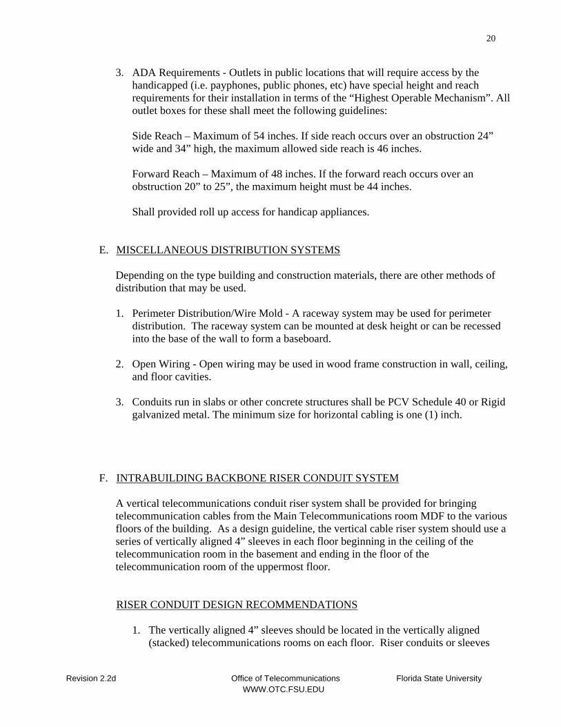
Table 2 Usable Building Floor Area Recommended Sleeve Quantities U (x 100 Ft. Sq.) U U No. Of Sleeves 0 - 129 4 (minimum) 130 - 259 6 260 - 389 8 390 - 520 10
II. TELECOMMUNICATIONS ROOMS / EQUIPMENT ROOMS
A. UDEFINITION
Revision 2.2d Office of Telecommunications Florida State University WWW.OTC.FSU.EDU
22
This section identifies 3 (three) physical spaces within a building that are critical to the proper management and transport of telecommunications (voice, video, data) services. They are the Main Telecommunications Room (MTC), Telecommunications Rooms (TC) and the Customer Premise Equipment (CPE) Room. Any of these rooms may be referred to as a Telecom Room.
The primary telecommunications room for the entire building is the Main Telecommunications Room (MTC). This room serves as the entrance facility for the building where all outside plant conduits terminate. It houses the Main Distribution Frame (MDF), where the service entrance cables terminate and interface with the intra-building backbone distribution cabling system and to the horizontal cross-connect and cabling serving that floor. The MDF is considered the point where the regulated telephone company will install the building entrance protectors. This point of interface is called the demarcation point. The demarcation point is where the cabling responsibility of the Service Provider (regulated telephone company) ends and where the cabling and equipment responsibility of the University OTC begins.
Other wiring rooms/rooms within a building are referred to as Telecommunications Rooms (TC). TC’s are “floor serving”. There shall be a minimum of one TC per floor. A TC is not required on the same floor as an MTC unless needed due to cable length requirements. It is recommended that multiple TC’s should be provided on the same floor if usable floor space exceeds 10,000 sq ft. UorU the conduit length between the horizontal cross-connect in the TC and any Telecommunication outlets being served would exceed 270 total feet. Maximum allowed length of horizontal cable installed to outlets must not exceed 295 feet. Pathway length should be kept to a maximum of 270 feet to accommodate the cable length. The MTC and TC rooms contain the intermediate distribution frames (IDF’s) which include the terminations for the backbone cables in the riser system coming from the MDF and the terminations for the horizontal cabling and cross connects on the floor served. In addition to cable terminations and cross connects in these rooms they may in some cases serve as an equipment room for data, video and other equipment.
The Main Telecommunications room MTC and TC rooms are not to be shared facilities for other services and therefore should not house electrical equipment, plumbing, janitor sinks, or to be used as a storage area. HVAC Duct other than that serving the room, electrical conduits for other areas, sprinkler system piping, drain pipes, steam pipes, chilled water pipes, or any other systems should not be routed through the interior of the MTC, TC or CPE rooms. Any other conceived use for the telecommunications rooms that don’t follow the intended use of telecommunications is not permitted.
The design professional shall make provisions for separate CPE room(s) within newly designed and renovated buildings. This room will house private departmental / customer computer and server equipment. Such rooms shall be contiguous to the MTC and TC rooms. If this is not possible, these areas shall be connected via a series of 4”conduits. If the rooms can not be contiguous, the designs must be approved by the OTC
Revision 2.2d Office of Telecommunications Florida State University WWW.OTC.FSU.EDU
23
B. UREQUIREMENTSU
1. UMTC / TC Room(s)U - shall include the following:
a. Wall Linings - All walls should be finished, i.e. sheet-rock/painted, and lined with
3/4 inch thick, A/C or B/C Grade Plywood backboard, 8 foot high by 4 foot wide and affixed in such a manner that it will support the weight of the cable, terminals, and other equipment. This allows for coverage of the entire area on which connecting hardware and cable management hardware may be mounted. The plywood should extend around the entire room, corner to corner on every wall. Smooth side shall be installed out. The plywood backboard shall be void free and treated with two coats of fire retardant paint materials. Use flush hardware and supports to mount plywood. The strength and placement of mounting hardware shall be sufficient to handle the total anticipated load (static and dynamic) and mounting of cabling components. The placement of the plywood backboard shall be on top of the wall covering, i.e. sheet-rock, etc. and is not a substitute for the wall covering.
b. Lighting recommendations -
• A light intensity level of 70 foot candles minimum should be provided measured at 3.3 feet from the finished floor.
• Do not use dimmer switches. • Locate light fixtures a minimum of 8’, 6” above the finished floor. • Emergency lighting is recommended if available.
c. Power –
• Provide at least one dedicated 120 VAC 20 amp (non-switchable) quad receptacle on each wall.
• Locate receptacles at least 6 inches above finished floor. • Receptacles must not be controlled by wall switches. • Provide one (1) dedicated 120 VAC 20 amp (non-switched) outlet to be
installed at the top and end of the End Relay Rack in each communications room. Placement of the relay racks are done by the FSU Office of Telecommunications. The Electrical Contractor shall coordinate the placement of the electrical outlet with the Office of Telecommunications design professional.
• If the building is provided with an emergency generator system or UPS (uninterruptible power supply), the electrical power and lights in the MTC / TC room shall be supplied from that power source.
• Switches, thermostats or other devices shall be installed beside the door and not in walls containing telecommunications backboards. At no time should these devices be mounted on walls that will contain the TBB or CBB (Communications Backboards).
d. Room Sizing –
Revision 2.2d Office of Telecommunications Florida State University WWW.OTC.FSU.EDU
24
1) MTC / TC Room Sizing - The recommended minimum floor dimension for an
MTC shall be 90 square feet (i.e. 9’ x 10’) and the minimum TC on each floor shall be 70 square feet (i.e. 7’ x 10’). These minimum sizes shall be increased as building size, floor square footage served or usage increases. The design professional shall consult with the OTC design professionals if any questions arise concerning the proper sizing. The following recommendations are made for sizing of both MTC and TC:
UArea Served U URoom DimensionsU
5,000 sq ft or less 70 sq ft (i.e. 7’ x 10’) 5,000 sq ft to 8,000 sq ft 90 sq ft (i.e. 9’ x 10’) 8,000 sq ft to 10,000 sq ft 110 sq ft (i.e. 10’ x 11’) **Single floors that are above 10,000 ft may require an additional communications room due to limits on communications cable lengths.
2) Smaller Single Story Buildings – In smaller single story buildings less space is needed. In most cases there will be only one Telecommunications Room, Room or Terminal Can. The following minimum is recommended for these applications:
UBuilding Floor Area ServedU UServed by
Less than 5,000 sq ft Shallow Room (3’ x 8.5 ‘) Walk in room (5’ x 5’) Less than 1,000 sq ft Wall Cabinets, Enclosures, etc. Note: The design professional shall work with OTC design professionals to determine the sizing of any cabinets or enclosures.
e. Work Clearance - The NEC Section 110-16 provides requirements for working space and clearance around electrical equipment that is exposed (i.e. unguarded, uninsulated).
Provide the following clearances for equipment and cross connect fields in the TR: • Allow a minimum of 1 meter (3.3 ft) of clear working space from equipment
and the wall where wall mounted cross-connect fields are being mounted when determining the size of the Room.
• Allow for 6 inches depth off wall for wall mounted equipment. • Provide space of at least 4 feet from center line of rack to wall in front and in
rear of each equipment rack or cabinet. Provide isles at least 32 inches wide. • In corners a side clearance of 12inches is recommended.
Revision 2.2d Office of Telecommunications Florida State University WWW.OTC.FSU.EDU
25
f. Relay Racks are typically installed in MTC, TC and CPE rooms for the
termination of horizontal data cabling, fiber optics and LAN and other equipment. Installation is typically made by the university OTC. The size of a typical Relay Rack is 19 inches wide, 7 feet 6 inches high, has a 32” footprint and meets ANSI/EIA-310D.
g. RFI / EMI Restrictions –
• Due to RFI and EMI the MTC/TC/CPE rooms shall not house any electrical equipment (i.e. - step down or step up transformers, breaker panels, etc).
• The equipment room shall be in a location where electromagnetic interference is minimal.
h. Pathway Installation –
• Conduits are to be clamped to the wall so that they will support the pulling of cable and be bonded to the Telecommunications ground.
• Conduits shall be dressed even, reamed, cleaned, bushings installed and contain pull cord capable of 200 lbs of pull strength. Sleeves, conduits and raceways must not be left open after installation of cabling. Once cable is installed firestop all sleeves, conduits, and raceways in accordance with building codes.
i. If two telecommunications rooms are located on the same floor they should be
connected with a minimum of 2 - 4 inch conduits. Terminate conduits through the structural floor in the telecommunications rooms three (3) inches above the floor surface. For conduits entering from the ceiling or walls the conduits should be installed to turn down and extend to 8 1/2 feet above finished floor in the Telecommunications rooms or equipment rooms. All conduits shall be dressed at the same level and installed with rigid conduit straps to the wall. Design professionals and installation contractors shall contact the OTC project manager to address exceptions due to structural conflicts.
j. Cable Tray - Each MTC and TC shall have Cable Tray for the routing of cable inside the rooms that is a minimum of 12” wide installed from corner to corner on every wall mounted 8 feet above finished floor. All tray must be bonded and grounded to the Telecom ground bus bar for the room. Typical cable tray shall be Homaco TRC-512 with all associated hardware. Substitutes must be approved by the OTC. When cable trays are approved for use verses conduit for horizontal cabling they should protrude into the telecommunication room and be installed in a continuous loop around the room at the top edge of the 8 foot high TBB which should be on all four walls of the room. Sizing and manufacturer shall be coordinated with OTC.
k. Ceilings –
Revision 2.2d Office of Telecommunications Florida State University WWW.OTC.FSU.EDU
26
• To permit maximum flexibility and accessibility, false ceilings (drop ceilings) are UnotU permitted in MTC or TC rooms.
• Over-head clearances shall be at least 8 feet (i.e. HVAC duct work, sprinkler heads, etc).
l. Location –
• To minimize the horizontal cable lengths within a maximum of 295 feet, locate the telecommunications room / room (TC) on each floor as close as possible to the center of the area it is to serve.
• Ensure that the Telecom rooms are directly accessible from the hallway or other common area. Telecom room should have only one door and not be used as a passage way to other rooms.
• It is recommended that all TC rooms be vertically aligned (stacked) above the MTC and each other.
m. Entry –
Personnel entry to MTC / TC room(s) shall be through a locked door at least 36 inches wide, 80 inches high. The door should open UoutwardU unless building codes prohibit. Doors swinging in eliminate three feet of usable wall space. In the advent that the door must swing in the design professional shall add the lost wall space in the design and increase room size to compensate. The door is to be keyed by the FSU key bank for the OTC equipment room key. In special applications where a Telecommunications Terminal Cabinet (Box) is used, the box installed shall be capable of being locked. Personal entry to a locked panel shall be via an FSU key bank key for the OTC.
n. Dust Elimination –
The walls and ceilings of all equipment rooms shall be dust free and painted with a light color latex paint. The floor shall be tiled with VCT or concrete which has been sealed with sealant.
o. Room Layout - In new buildings the MTC and TC’s shall be designed to be
vertically stacked directly over each other. The MTC and TC rooms shall be laid out as to allow for proper use of space.
• All Outside Plant (OSP) 4” conduits entering the MTC shall be located on one
wall, preferably starting in the left-hand corner inside the door. If it is not possible to locate in the left-hand corner inside the door, Conduits should be installed beginning in a corner of the room. Avoid installing the OSP conduits or Riser sleeves in the middle of the backboard (wall).
• It is recommended that the 4” intra-building backbone riser sleeves be placed directly above the OSP conduits in the MTC and in the same location in each stacked TC room so straight pulls can be made from the floor sleeves to the ceiling sleeves.
Revision 2.2d Office of Telecommunications Florida State University WWW.OTC.FSU.EDU
27
• Horizontal conduits shall enter on another wall and other services shall be properly distributed along the remaining walls. Any questions about room layout should be directed to the OTC design professional.
• Avoid mixing 4" entrance, riser and horizontal conduits. p. Grounding / Bonding – Refer to Section V for requirements.
q. Fire Protection – Provide fire protection for MTC and TC rooms if required by
applicable codes.
r. Environmental Control – Provide heating, ventilation and air conditioning that will maintain continuous and dedicated environmental control 24 hours per day, 365 days per year. Since the MTC and TC rooms house equipment the normal temperature range should be 65 degrees to 78 degrees with 30% to 55% relative humidity. Switches, thermostats or other devices shall be installed beside the door and not in walls containing telecommunications backboards. At no time should these devices be mounted on walls that will contain the CBB (Communications Backboards)
2. UCustomer Premise Equipment (CPE) RoomsU
Some projects may require CPE Room(s) be designed – If CPE rooms are requested
in a project by the university they shall include the following:
a. Wall Linings - At least one wall should be lined with 3/4 inch thick, A/C or B/C Grade Plywood backboard, 8 feet high by 4 feet wide and affixed in such a manner that it will support the weight of the cable, terminals, and other equipment. This allows for coverage of the entire area on which connecting hardware and cable management hardware may be mounted. The plywood should extend from wall to wall. Smooth side shall be out. The plywood backboard shall be void free and treated with two coats of fire retardant paint materials. Use flush hardware and supports to mount plywood. The strength and placement of mounting hardware shall be sufficient to handle the total anticipated load (static and dynamic) and mounting of cabling components. The placement of the plywood backboard shall be on top of the wall covering, i.e. sheet-rock, etc. and is not a substitute for the wall covering.
b. Lighting –
• A light intensity level of 70 foot candles minimum should be provided measured at 3.3 ft from the finished floor.
• Do not use dimmer switches. • Locate light fixtures a minimum of 8 ft. 6 in. above the finished floor. • Emergency lighting is recommended if available.
c. Power –
Revision 2.2d Office of Telecommunications Florida State University WWW.OTC.FSU.EDU
28
• Provide at least one dedicated 120VAC, 20 amp (non-switchable) quad receptacle on each wall.
• Locate receptacles at least 6 inches above finished floor but not higher than 15”.
• Receptacles must not be controlled by wall switches. • If the building is provided with an emergency generator system or UPS
(uninterruptible power supply), the electrical power and lights in the CPE room shall be supplied from that power source.
• Switches, thermostats or other devices shall be installed beside the door and not in walls containing telecommunications backboards. At no time should these devices be mounted on walls that will contain the CBB (Communications Backboards)
d. Room Sizing - The minimum floor dimension for a CPE room contiguous to a MTC or TC room shall be 64 square feet (8’x8’). The minimum floor dimension for a CPE room contiguous to an TC room shall be 24 square feet (6'x 4'). These minimum sizes shall increase as building size and usage increase. The design professional shall consult with the OTC if any questions arise. The NEC Section 110-16 provides requirements for working space and clearance around electrical equipment that is exposed (i.e. unguarded, uninsulated).
e. RFI / EMI Restrictions –
• Due to RFI and EMI the CPE rooms shall not house any electrical equipment (i.e. - step down or step up transformers, breaker panels, etc).
• The equipment room shall be in a location where electromagnetic interference is minimal.
f. Pathway Installation –
• All conduits and cable trays connecting the MTC or TC rooms to the CPE room shall enter on the same wall that the plywood was attached and extend up or down to the edge of the backboard. The CPE should be connected to the serving MC or TC with a minimum of one 4 inch conduit. Conduits are to be clamped to the wall so that they will support the pulling of cable and be bonded to the Telecommunications ground.
• Conduits shall be dressed even, reamed, cleaned, bushings installed and contain pull cord capable of 200 lbs of pull strength.
• Sleeves, conduits and raceways must not be left open after installation of cable. Once cable is installed firestop all sleeves, conduits, and raceways in accordance with building codes.
• Conduits entering from the floor shall extend 3 inches above finished floor. For conduits entering from the ceiling or walls the conduits should be installed to turn down and extend to 8 1/2 feet above finished floor in the Telecommunications rooms or equipment rooms. All conduits shall be dressed at the same level and installed with rigid conduit straps to the wall. Design
Revision 2.2d Office of Telecommunications Florida State University WWW.OTC.FSU.EDU
29
professionals and installation contractors shall contact the OTC project manager to address exceptions due to structural conflicts.
g. Ceilings – • To permit maximum flexibility and accessibility, false ceilings (drop ceilings)
are UnotU recommended in MTC or TC rooms. • Over head clearances shall be at least 8 feet (i.e. HVAC duct work).
h. Location – CPE rooms shall be contiguous to the MTC and TC rooms due to the
requirements for horizontal cabling lengths. If this is not possible, these rooms shall be connected via a series of 4”conduits and the location should be so as to guarantee that the maximum horizontal cable links lengths do not exceed 295 feet from the horizontal termination in the CPE to the Workstation outlet.
i. Entry - Personnel entry to MTC / TC room(s) shall be through a locked door at
least 36 inches wide, 80 inches high. The door should open UoutwardU unless building codes prohibit. Doors swinging in eliminate three feet of usable wall space. In the advent that the door must swing in the design professional shall add the lost wall space in the design and increase room size to compensate. The door is to be keyed by the FSU key bank for the OTC equipment room key. In special applications where a Telecommunications Terminal Cabinet (Box) is used, the box installed shall be capable of being locked. Personal entry to a locked panel shall be via an FSU key bank key for the OTC.
j. Dust Elimination - The walls and ceilings of all equipment rooms shall be dust
free and painted with a light color latex paint. The floor shall be tiled with VCT or concrete which has been sealed with sealant.
k. Room Layout -
• Conduits entering the CPE room shall extend to the Plywood backboard or approximately 8 1/2 feet AFF. Cable Trays located within the ceiling space of the room should never be below 8 feet from the finished floor. Conduits and cable tray shall be rigidly installed to the walls.
• For specific CPE room layout the design professional shall consult with the OTC design professional.
l. Work Clearance - The NEC Section 110-16 provides requirements for working
space and clearance around electrical equipment that is exposed (i.e. unguarded, uninsulated).
Provide the following clearances for equipment and cross connect fields in the Equipment room:
Revision 2.2d Office of Telecommunications Florida State University WWW.OTC.FSU.EDU
30
• Allow a minimum of 1 meter (3.3 ft) of clear working space from equipment and the wall where wall mounted cross-connect fields are being mounted when determining the size of the Room.
• Allow for 6 inches depth off wall for wall mounted equipment. • Provide space of at least 4 feet from center line of rack to wall in front and in
rear of each equipment rack or cabinet. Provide isles at least 32 inches wide. • In corners a side clearance of 12inches is recommended.
Relay Racks are typically installed in MTC, TC and CPE rooms for the termination of horizontal data cabling, fiber optics and LAN and other equipment. Installation is typically made by the university OTC. The size of a typical Relay Rack is 19 inches wide, 7 feet 6 inches high, have a 32” footprint and meet ANSI/EIA-310D.
m. Grounding / Bonding – Refer to Section V for requirements.
n. Fire Protection – Provide fire protection for CPE rooms if required by applicable
codes. o. Environmental Control – Provide heating, ventilation and air conditioning that
will maintain continuous and dedicated environmental control 24 hours per day, 365 days per year. Since this room houses equipment it is recommended that at a minimum temperature range should be 65 degrees to 78 degrees with 30% to 55% relative humidity. For specific application the design professional shall consult with the department to obtain current heat load data and future heat load data. Switches, thermostats or other devices shall be installed beside the door and not in walls containing telecommunications backboards. At no time should these devices be mounted on walls that will contain the CBB (Communications Backboards)
3. UCabinets and Terminal BoxesU –
For existing installations, retrofits and smaller one story buildings, it is recognized that a dedicated room may not be an option. If a dedicated MTC or TC room can not be constructed, then the requirements for a locked terminal box on an exposed wall space terminal location shall be used. The terminal boxes shall include:
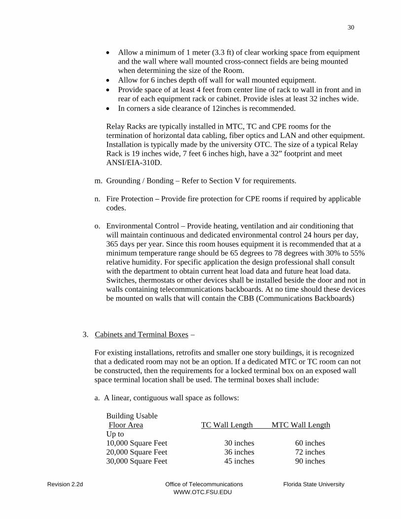
a. A linear, contiguous wall space as follows:
Building Usable UFloor AreaU UTC Wall Length MTC Wall LengthU
Up to 10,000 Square Feet 30 inches 60 inches 20,000 Square Feet 36 inches 72 inches 30,000 Square Feet 45 inches 90 inches
Revision 2.2d Office of Telecommunications Florida State University WWW.OTC.FSU.EDU
31
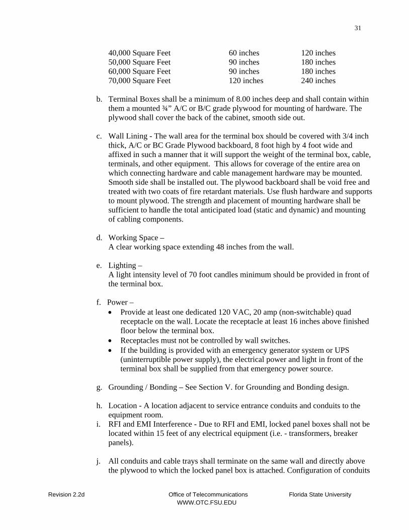
40,000 Square Feet 60 inches 120 inches 50,000 Square Feet 90 inches 180 inches 60,000 Square Feet 90 inches 180 inches 70,000 Square Feet 120 inches 240 inches
b. Terminal Boxes shall be a minimum of 8.00 inches deep and shall contain within them a mounted ¾” A/C or B/C grade plywood for mounting of hardware. The plywood shall cover the back of the cabinet, smooth side out.
c. Wall Lining - The wall area for the terminal box should be covered with 3/4 inch
thick, A/C or BC Grade Plywood backboard, 8 foot high by 4 foot wide and affixed in such a manner that it will support the weight of the terminal box, cable, terminals, and other equipment. This allows for coverage of the entire area on which connecting hardware and cable management hardware may be mounted. Smooth side shall be installed out. The plywood backboard shall be void free and treated with two coats of fire retardant materials. Use flush hardware and supports to mount plywood. The strength and placement of mounting hardware shall be sufficient to handle the total anticipated load (static and dynamic) and mounting of cabling components.
d. Working Space –
A clear working space extending 48 inches from the wall.
e. Lighting – A light intensity level of 70 foot candles minimum should be provided in front of the terminal box.
f. Power –
• Provide at least one dedicated 120 VAC, 20 amp (non-switchable) quad receptacle on the wall. Locate the receptacle at least 16 inches above finished floor below the terminal box.
• Receptacles must not be controlled by wall switches. • If the building is provided with an emergency generator system or UPS
(uninterruptible power supply), the electrical power and light in front of the terminal box shall be supplied from that emergency power source.
g. Grounding / Bonding – See Section V. for Grounding and Bonding design.
h. Location - A location adjacent to service entrance conduits and conduits to the
equipment room. i. RFI and EMI Interference - Due to RFI and EMI, locked panel boxes shall not be
located within 15 feet of any electrical equipment (i.e. - transformers, breaker panels).
j. All conduits and cable trays shall terminate on the same wall and directly above
the plywood to which the locked panel box is attached. Configuration of conduits
Revision 2.2d Office of Telecommunications Florida State University WWW.OTC.FSU.EDU
32
and cable tray shall follow the same design configuration requirements as the MTC and TC rooms.
k. Overhead clearance – Over-head clearances shall be at least 8 feet, 6 inches.
Piping, HVAC duct work, sprinkler heads, etc shall be placed to assure a minimum clearance of 8 feet.
III. TELECOMMUNICATIONS GROUNDING AND BONDING
Statement: The information provided in this document for the design of the Telecommunications grounding and bonding system does not replace national, state, local or other applicable codes, laws or regulations.
Telecommunications grounding and bonding is additional grounding and bonding specifically for telecommunications systems and serves to minimize electrical effects and hazards, augment electrical bonding, and lower the system ground reference potential. Requirements and guidelines for this system are found in ANSI/TIA/EIA-607.
A. UGROUNDING PRACTICESU
1. Main Ground –
• The first choice for connection of the Telecommunications Grounding/Bonding system is direct attachment to the closest point in the buildings electrical service grounding electrode system. Electrical power cabling and Communications cabling must be effectively equalized.(refer NEC 800-40). The architect and engineer shall provide in the design that a 4.0 AWG copper bonding conductor be provided to the CBB or TBB (backboard) of the MTC and each MC for connection to the Telecommunications grounding and bonding system. This ground shall be installed by a qualified electrician. OTC personnel will install the grounding and bonding riser and connect telecommunications panels and other equipment.
• In buildings without electrical service install a driven ground rod which is ½” in diameter and 8 ft. long.
• If the ground conductor is installed in conduit or raceway, the conduit or raceway must be bonded on both ends to the ground.
IV. OTHER
A. UCAMPUS MASTER PLAN
FSU has developed both a ten year and twenty year campus master plan which will include documentation of telecommunications services for existing and future buildings. New construction and renovation projects planners should reference this plan and consider the installation of new OSP facilities and support services back to a central distribution point when establishing cost estimates and budgets. Planners should work
Revision 2.2d Office of Telecommunications Florida State University WWW.OTC.FSU.EDU
33
closely with the OTC and the Central Utilities Plant (CUP) to assure bell circuits, fire alarms, energy management systems are considered and installed.
B. UINSPECTION AND TESTING DURING AND AFTER INSTALLATIONU
Frequent inspections should be conducted during the installation of the new services and wiring. These inspections should be conducted jointly by the University’s project manager and the staff person directly responsible for building services. It is important that the design engineer work with the OTC, ACNS, and the University Project Coordinator to outline the specific tests the contractor must perform to gain acceptance of the new services. All finished test results shall be delivered to the Office of Telecommunications. Failure to do so will place the project in an incomplete status and shall stop final payment due installer.
C. UCOIN OPERATED TELEPHONESU
Unless otherwise specified, provisions shall be made for public coin operated telephone facilities in public access areas. If only one coin operated telephone facility is required, it shall be located to permit usage by handicapped individuals. The telephone outlets for public coin operated telephones shall be located at a height that will permit the installation of normal height telephone mounts and/or lowered height telephone mounts for the handicapped without exposure of the telephone outlets for either installation. All public access telephones shall meet the American’s with Disabilities Act of 1992.
D. UBLUE LIGHT EMERGENCY TELEPHONESU
The construction budget for renovations or new facilities should include the costs of conduit, Talk-A-Phone Emergency Telephones and hardware necessary to install emergency phones. The Office of Telecommunications installs the cabling and telephone line required. The exact location of instruments shall be recommended by the Public Safety Office within the Florida State University Police Department. Talk-A-Phone units require AC power for the lighting which should be dedicated, 20 Amp, Non-switched service. The two most common Units which are to be used for exterior installations are listed below. Model numbers and features change frequently so the Office of Telecommunications should be contacted for current model numbers: 1. Blue Light Emergency Phones
a. Tower Emergency Phone Unit
Talk-A-Phone, Tower with ETP-400 Phone, Part NumberU ETP-MT/R-FSU Note: Tower unit to have circulation vent
b. Wall Mounted Emergency Phone Unit
Revision 2.2d Office of Telecommunications Florida State University WWW.OTC.FSU.EDU
34
Talk-A-Phone, Wall Mount unit with ETP-400 Phone, Part NumberU ETP-WM-FSU/400
Internal Emergency Phones – Emergency phones located inside require the following:
A dedicated 1”” homerun conduit shall be run from the telecommunications room for the voice line to a FME – Flush Mount Enclosure box where the phone is to be installed. See ADA requirements for height of the enclosure. A 120 volt A/C, 20 amp dedicated circuit shall be provided to a single gang outlet mounted in the bottom of the FME Box. The design professional should consult with the OTC concerning the university instrument of choice or any required signaling devices.
E. UELEVATOR TELEPHONESU
The construction budget for renovations or new facilities should include the costs of elevator telephones. The OTC will install and maintain all elevator telephones on campus; however, the design professionals must ensure that the conduit is installed. Instrumentation cost shall be budgeted by the construction manager.
F. UWIRELESS APPLICATIONSU
In today’s complex wiring environment sometimes wired services equal wireless services. If the design professional sees a need for wireless applications or has a request from the customer they should consult the Office of Telecommunications. This would include wireless application in the areas of data or voice or video.
G. UDOCUMENTATIONU
At the completion of each installation “As Built” prints and other supporting documentation shall be provided by those performing work specified in this document. Prior to the beginning of university major and minor constructon projects, a complete set of 100% prints and documentation shall be provided to the OTC Engineering group for review and will be maintained on file.
V. APPLICABLE CODES AND STANDARDS
The design and installation of FSU telecommunications infrastructure attempts to meet parameters of all applicable local, state and national codes and standards. Issues that fall under codes are a requirement. Though many telecommunications design issues fall under established standards that are not code, these standards have been adopted at FSU and it is highly recommended by this office that the standards listed in this document be followed. At times, conflicts arise between published guidelines such as REA, EIA, TIA, NFPA, IEEE, NCTA, BICSI, and individual company policies. Therefore, this document reflects portions of and/or references the following specifications. Drawing and design documents should be
Revision 2.2d Office of Telecommunications Florida State University WWW.OTC.FSU.EDU
35
specific for each project and include, either as a direct excerpt or by reference, information from these sources:
• AT&T, former Bell System Practices (BSP’s) • General Telephone, installation and construction practices • Northern Telecom, installation practices • RUS (formerly REA), Rural Utilities Services USDA/RUS • BICSI, Telecommunications Distribution Methods Manual • ANSI/TIA/EIA-568A, Commercial Building Telecommunications Cabling Standard.S S • TIA/EIA TSB-67 Transmission Performance Specifications for Field Testing of
Unshielded Twisted Pair Cabling Systems. • TIA/EIA TSB-75, Additional Horizontal Cabling Practices for Open Offices. • ANSI/TIA/EIA-569A, Commercial Building Standard for Telecommunications
Pathways and Spaces. • ANSI/TIA/EIA-606, Administration Standard for Telecommunications Infrastructure
of Commercial Buildings. • ANSI/TIA/EIA-607, Commercial Building Grounding and Bonding Requirements for
Telecommunications. • ANSI/NFPA-70, National Electrical Code • NFPA-101, Life Safety Code • NFPA-780, Standard for the Installation of Lightning Protection Systems. • Other applicable NFPA Codes. • ANSI/IEEE Codes, All Applicable Codes. • NESC, National Electrical Safety Code (ANSI/IEEE C-2, overhead and underground
telecommunications cable). • ISO/IEC 11801, Information Technology. Cabling for Customer Premises. • IEC 603-7, Part 7, Modular Connectors • FCC Part 68, Connection of Terminal Equipment to the telephone network. • FCC Part 15, Radiation Limits. • FCC Part 76, Cable TV Service. Code of Federal Regulations (CFR) – 10CFR47, Part
76.605. Signal Quality for CATV. Federal Communications Commission (FCC). • Publications and Industry Standards for CATV. Society for Cable Television
Engineers (SCTE) • Local Uniform Building Codes • National Cable Television Association Handbook • General Instruments/Hewlett Packard, broadband testing procedures • Individual university facility and construction guidelines • Department of Management SGeneralS Services, Division of Communications, State of
Florida. • Americans with Disabilities Act, 1992
Finished drawing and design documents should not conflict with the above standards and should not deviate from the intent or spirit of this document. It is the responsibility of the design professional for all designs to meet the most current codes and standards at the time of construction.
Revision 2.2d Office of Telecommunications Florida State University WWW.OTC.FSU.EDU
36
VI. GLOSSARY OF TERMS
ADA Americans with Disabilities Act
Aerial Service Telecommunications Cable installed on supporting structures such as poles, sides or buildings, and other structures.
ANSI American National Standards Institute
ASTM American Society for Testing and Materials
AWG American Wire Gauge
Backboard Plywood covered wall in telecommunications room or in terminal
boxes used to mount termination devices, hardware and equipment.
Backbone Cabling and pathway used to connect the telecommunications rooms, cross-connects, entrance facilities and equipment rooms.
Bridge Tap The connection of two circuits in parallel to each other or a cable
pair continued beyond the point at which the pair is connected to an instrument.
Buried Service A cable installed under the surface of the ground (not in conduit) in
such a manner that it cannot be removed without disturbing the soil. Also called direct buried cable, trenched, or bored.
Busbar A copper bar used as a common point for connection of the building
electrical service ground to all telecommunications hardware and equipment in a room or terminal box.
Cable Bend Radius The radius that a cable can bend before risk of damage or decrease in
transmission performance.
CATV Community Antenna Television (Cable TV)
Coax Coaxial Cable. A central conductor surrounded by dialectric and a tubular outer conductor.
Conduit Ductbank An arrangement of conduit ducts in tiers, encased in concrete used
for installing telecommunications cables between buildings.
Revision 2.2d Office of Telecommunications Florida State University WWW.OTC.FSU.EDU
37
CPE Room Customer Premise Equipment Room. Often called Data Equipment
Room. This room houses private departmental / customer equipment.
Cross Connection A connection made between cables, subsystems and equipment by the use of patch cables, or jumper wires run between the terminating devices.
CUP Florida State University Central Utility Plant.
D Ring Cable Management Device attached to the backboard.
dB Decibel
Demarcation point A point of interface where two services are connected. An example at FSU would be the point at which the local dial tone provider terminates their cables in the Main Telecommunications Room for cross-connection to the Intrabuilding cabling.
EIA Electronics Industries Association.
EMI Electromagnetic Interference. An unacceptable or undesired
response, malfunction, degradation, or interruption to the intended operation of electronic equipment caused by the coupling of electrical or magnetic fields.
EMT Electrical Metallic Tubing
Encased Conduit Conduit contained inside poured concrete.
Exposed Cable Any cable that is located so that it is subject to lightning, power
induction, or differences in ground potentials.
F Connector Coaxial Connector commonly used for terminating CATV Cables.
Outlet Faceplate A plate or cover which holds multiple communications jacks, mounted on a surface, and covering the electrical box and communications cables in the wall.
FCC Federal Communications Commission
FDDI Fiber Distribution Data Interface
Foot-Candle a unit of illuminance on a surface that is everywhere one foot from a uniform point source of light of one candle and equal to one lumen per square foot
Revision 2.2d Office of Telecommunications Florida State University WWW.OTC.FSU.EDU
38
Gas Tube Protector An Overvoltage Protector with metallic electrodes in a gas
atmosphere contained in a glass or ceramic envelope.
Horizontal Channel The Horizontal cabling which includes all elements of the Horizontal cabling Link, plus the equipment cords in the telecommunications room and the work area. Contains all elements needed to support telecommunications applications over the horizontal cabling.
Horizontal Link The horizontal cabling which includes all horizontal components
except for equipment cords in the telecommunications room and at the work station.
ICEA Insulated Cable Engineers Association
IDF Intermediate Distribution Frame. A field of termination devices on
which the intrabuilding backbone cables are terminated for cross-connection to the horizontal cabling system. Normally found in the Telecommunications Room on each floor.
IEC International Electromechanical Commission.
IEEE Institute of Electrical and Electronics Engineers, Inc.
Interbuilding Backbone A Cable between two buildings. ISDN Integrated Services Digital Network. A integrated data network in
which the same time division switches and digital transmission paths are used to establish connection for different services.
ISO International Standards Organization KV KiloVolts (1000 volts) LAN Local Area Network. A geographically limited data network used for
the local transport of voice, data, and video. Loose Buffer In a fiber optic communication cable, one type of component used to
encapsulate one or more optical fibers for the purpose of providing such functions as mechanical isolation, protection from physical damage and fiber identification. The buffer may take the form of a miniature conduit, contained within the cable and called a loose buffer, or loose buffer tube, in which one or more fibers may be enclosed, often with a lubricating gel.
Revision 2.2d Office of Telecommunications Florida State University WWW.OTC.FSU.EDU
39
Maintenance Loop An additional length of cable on the end of a installed cable that allows for later use if any of the cable must be shortened or the termination devices moved.
Manhole A hole through which a person may gain access into a underground
vault or structure. Marker tape A plastic tape placed in the ground to identify buried cable location
if dug up. MDF Main Distribution Frame. Also called the Main Cross-connect. The
cross-connect in the Main Telecommunications Room (room) where the entrance cables terminate and cross-connect to the building Intrabuilding Backbone Riser cables.
Media The physical path for telecommunications services. (i.e., copper
cable, fiber optic cable, coaxial cable, radio, etc.) Mhz Megahertz. One million hertz or one million cycles per second. Modular Jack insert The modular communications jack that snaps into a faceplate. MTC The Main Telecommunications Room (room) for the entire building.
This room serves as the entrance facility for the building where all Outside Conduits terminate. It houses the Main Distribution Frame (MDF), where the service entrance cables terminate and interface with the intrabuilding backbone distribution cabling system and to the horizontal cross-connect and cabling serving that floor. The MDF is considered the point where the regulated telephone company will install the building entrance protectors.
Multimode Fiber An optical fiber that supports the propagation of more than one
bound mode. A multimode optical fiber may be either a graded-index (GI) fiber or a step-index (SI) fiber.
MUX A device that combines multiple inputs into an aggregate signal to be
transported via a single transmission channel. NEC National Electrical Code. NESC National Electrical Safety Code. NFPA National Fire Protection Association. OFNP Optic Fiber Non-conductive Plenum.
Revision 2.2d Office of Telecommunications Florida State University WWW.OTC.FSU.EDU
40
OSHA Occupational Safety and Health Administration. OSP Outside Plant. Telecommunications facilities located outside of the
building. Either Underground, direct buried or aerial. OTC Office of Telecommunications Outlet A faceplate with modular jacks located at the workstation. Pathway Structures that conceal, protect, and support telecommunications
cables. (i.e. Conduit, cable rack, trays, J-hooks, underfloor ducts, cellular ducts, trench ducts, Raised access floor, etc.)
PBX Private Branch Exchange. Telephone system usually serving as a
small Central Office for the individual business and located on their site. Provides access to the public switch network.
PE Cable Filled Cable for use in OSP applications. Designated by the Rural
Utilities Service. Plenum rated Cable used in a designated area, closed or open, used for the
transport of environmental air. PSI Pounds per Square Inch Pull Box A device to access a raceway, used for access to allow for pulling
cable. Pulling Eye Metal loop securely fixed to the end of a cable or anchored in the
wall of a manhole to allow for the pulling of the cable into the ductbank.
PVC Polyvinyl Chloride Raceway An enclosed channel or pathway designed to hold cables. Relay Rack A vertical frame upon which one or more units of equipment and
patch panels are mounted. RFI Radio Frequency Interference. Any Radio Frequency disturbance
that interrupts, obstructs, or otherwise degrades or limits the effective performance of electronics/electrical equipment.
Riser Cable Intrabuilding Backbone Cable that runs vertically to the IDF in a
Telecommunications Room (room).
Revision 2.2d Office of Telecommunications Florida State University WWW.OTC.FSU.EDU
41
Single Mode Fiber A optical fiber in which the signal travels in one mode. The fiber has
a small core diameter, typically 8.3 µm. Sleeve A Conduit placed through a wall or floor to allow the passage of
telecommunications cables. Solid State Protector An Overvoltage Protector using high-power semiconductor
technology providing fast action and balanced circuits. STP Shielded Twisted Pair. A transmission line composed of a twisted 2-
wire metallic transmission line surrounded by a sheath of conductive material that protects it from the effects of external fields and confines fields produced within the line.
Sump, Manhole A fitting at the lowest point of the manhole floor used to pump a
manhole dry before working in it. T-1 (Carrier) A digital transmission system which operates on two twisted pairs at
a speed of 1.544 Mbps. The system is capable of carrying 24 channels (individual circuits) at 64Kbps.
TBB Telecommunications Bonding Backbone. A 6 AWG or large copper
conductor that provides for direct bonding and runs from the Telecommunications Main Bonding Busbar to the bonding busbar in each TC and CPE room.
TC Telecommunications Room. The Telecommunications Rooms (TC)
are “floor serving” and at least one is located on each floor. The IDF and Horizontal cable for the floor are usually located in the TC.
Telecom Telecommunications Terminal Block An insulating base with binding posts used to terminate
telecommunications cables and cross connect between cables. Terminal Box A metal box with a hinged lockable door used for installing terminal
blocks, terminating cables and cross connecting. The box provides protection against dust, mechanical damage, weather and vandalism.
TIA Telecommunications Industry Association Tight Buffer A tight buffer consists of a polymer coating in intimate contact with
the primary coating applied to the fiber during manufacture. The protective thermoplastic coating is normally a diameter of 900 microns.
Revision 2.2d Office of Telecommunications Florida State University WWW.OTC.FSU.EDU
42
TMGB Telecommunications Main Bonding Busbar. The main bonding
busbar is located in the Main Telecommunications Room and provides a connection point for the main building electrical service ground to safely carry lightning and other power fault currents away from the telecommunications systems. The TBB to other Telecommunications Rooms is connected to the TMGB.
TSB Technical Service Bulletin Underground Cable A telecommunications cable installed in a underground duct system
which separates the cable from direct contact with the soil. UPS Uninterruptible Power Supply USOC Universal Service Order Code UTP Unshielded Twisted Pair. A transmission line composed of a twisted
2-wire metallic transmission line surrounded by a sheath of non-conductive material.
Wire mold A surface mounted enclosed channel designed to hold cables. Workstation An individual user interface where the desk, computer,
communications, and other equipment is located and connected to the telecommunications outlet.
VII. ILLUSTRATIONS
Illustrations are to aid the design professional and installer in the development and installation of a telecommunications infra-structure in new and existing (renovation) projects. It includes recommended layouts for various infrastructure components and systems.
Revision 2.2d Office of Telecommunications Florida State University WWW.OTC.FSU.EDU
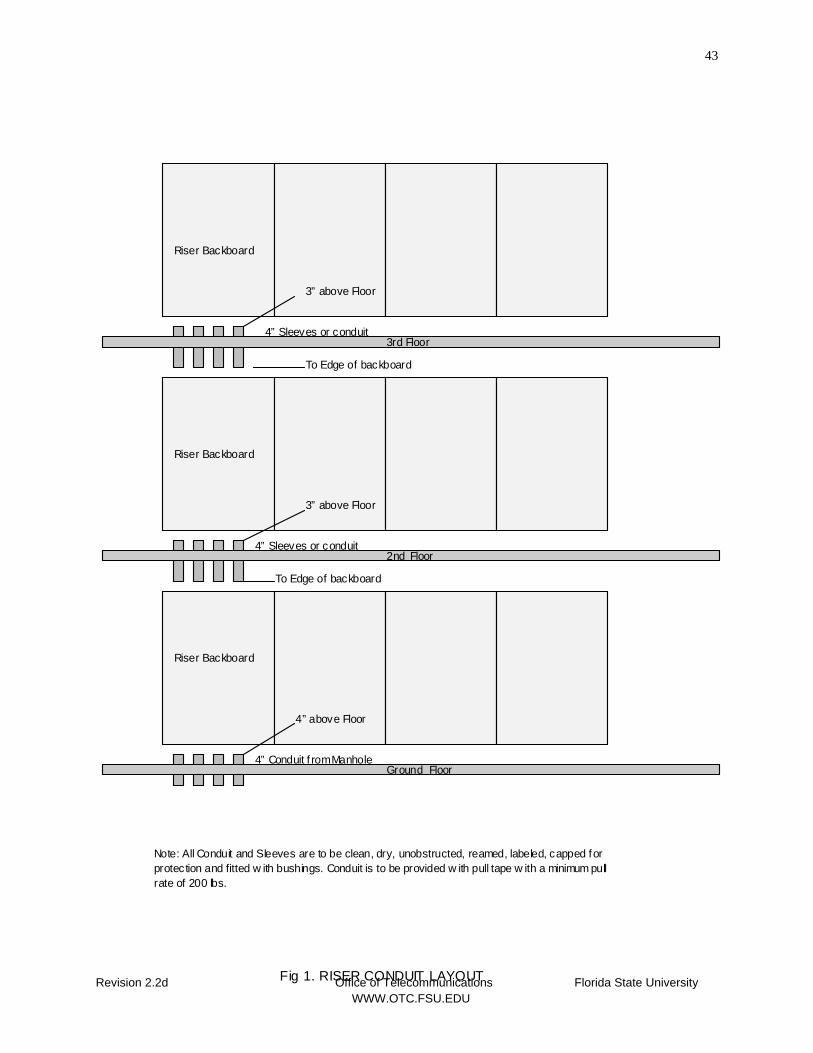
43
4” Sleeves or conduit
4” Conduit f rom Manhole
4” Sleeves or conduit
Riser Backboard
Riser Backboard
Riser Backboard
3” above Floor
3” above Floor
4” above Floor
2nd Floor
3rd Floor
Revision 2.2d Office of Telecommunications Florida State University WWW.OTC.FSU.EDU
Fig 1. RISER CONDUIT LAYOUT
Ground Floor
To Edge of backboard
To Edge of backboard
Note: All Conduit and Sleeves are to be clean, dry, unobstructed, reamed, labeled, capped for protection and fitted w ith bushings. Conduit is to be provided w ith pull tape w ith a minimum pullrate of 200 lbs.
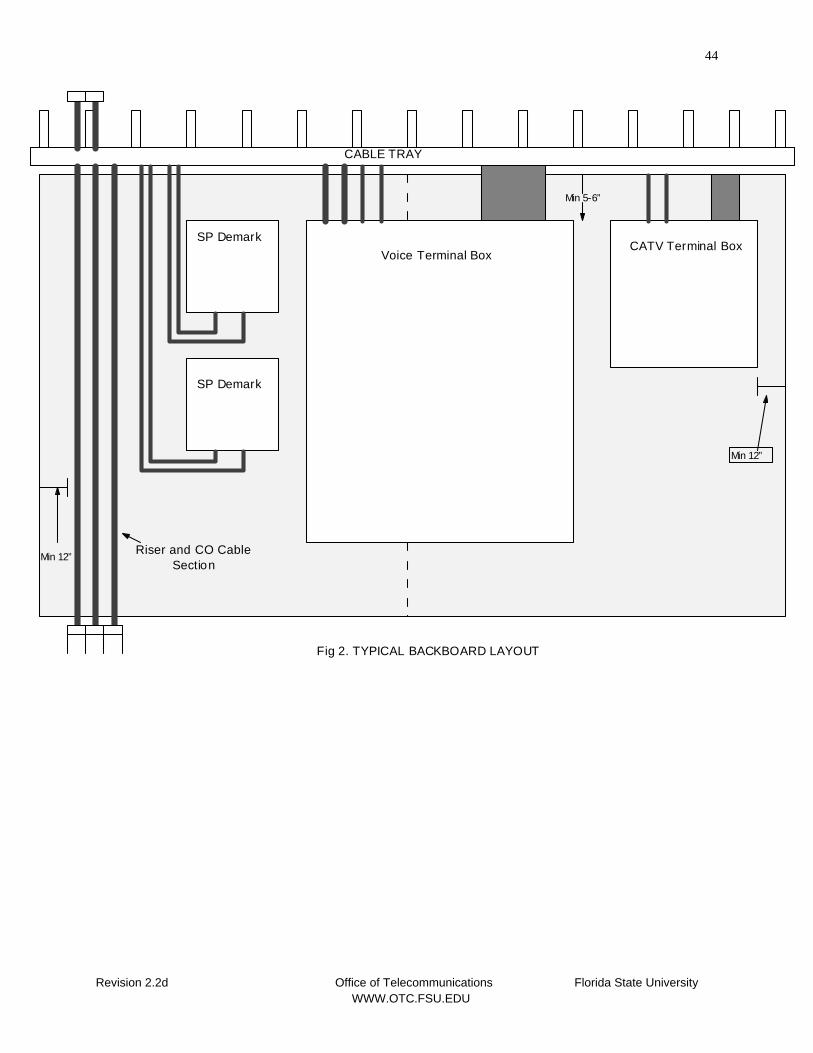
44
Fig 2. TYPICAL BACKBOARD LAYOUT
CABLE TRAY
SP Demark
SP Demark
Voice Terminal BoxCATV Terminal Box
Min 12”
Min 12”
Min 5-6”
Riser and CO Cable Section
Revision 2.2d Office of Telecommunications Florida State University WWW.OTC.FSU.EDU
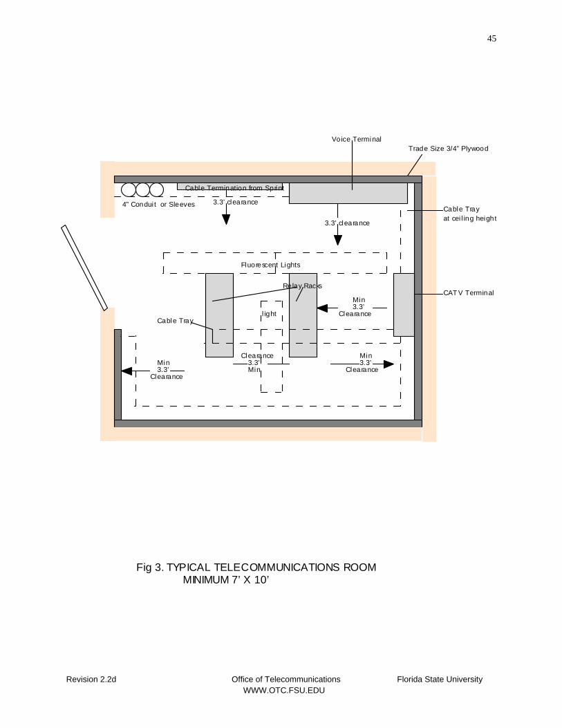
45
Trade Size 3/4” Plywood
4” Condui t or SleevesCable Trayat cei l ing height
Fluorescent Lights
3.3’
3.3’ clearance
Cable Termination from Sprint
3.3’
Voice Terminal
CAT V Terminal
3.3’MinMin
MinClearance
Clearance
Clearance
Relay Racks
Fig 3. TYPICAL TELECOMMUNICATIONS ROOM MINIMUM 7’ X 10’
3.3’ clearance
Min3.3’
ClearanceCable Tray
l ight
Revision 2.2d Office of Telecommunications Florida State University WWW.OTC.FSU.EDU
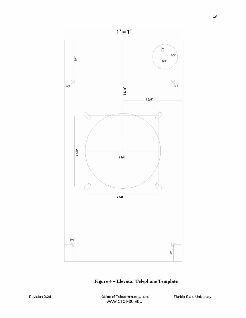
46
Figure 4 – Elevator Telephone Template
Revision 2.2d Office of Telecommunications Florida State University WWW.OTC.FSU.EDU


![PM[B] - GRAND CARNIVAL 2.2D EX - Naza · GRAND CARNIVAL 2.2D EX STANDARD SPECIFICATIONS INDIVIDUAL PRICE LIST Authorized Branch / Dealer: GST-JUL17-WV-YP-2.2DEX-B-PM NAZA KIA MALAYSIA](https://img.pdfslide.net/doc/110x75/5e60d66f083bbe175d48be6d/pmb-grand-carnival-22d-ex-grand-carnival-22d-ex-standard-specifications.jpg)