Embed Size (px)
Citation preview

This article was downloaded by: [213.0.109.161]On: 25 April 2014, At: 04:25Publisher: Taylor & FrancisInforma Ltd Registered in England and Wales Registered Number: 1072954 Registeredoffice: Mortimer House, 37-41 Mortimer Street, London W1T 3JH, UK
Journal of Nuclear Science andTechnologyPublication details, including instructions for authors andsubscription information:http://www.tandfonline.com/loi/tnst20
Flow Behavior and Phase Distribution inTwo-Phase Flow around Inverted U-BendKensuke USUI a , Shigebumi AOKI b & Akira INOUE ba Department of Mechanical Engineering II , Shibaura Institute ofTechnology , Tameihara, Fukasaku, Omiya-shi , 307b Research Laboratory for Nuclear Reactors , Tokyo Institute ofTechnology , Ookayama, Meguro-ku, Tokyo , 152Published online: 15 Mar 2012.
To cite this article: Kensuke USUI , Shigebumi AOKI & Akira INOUE (1983) Flow Behavior and PhaseDistribution in Two-Phase Flow around Inverted U-Bend, Journal of Nuclear Science and Technology,20:11, 915-928, DOI: 10.1080/18811248.1983.9733489
To link to this article: http://dx.doi.org/10.1080/18811248.1983.9733489
PLEASE SCROLL DOWN FOR ARTICLE
Taylor & Francis makes every effort to ensure the accuracy of all the information (the“Content”) contained in the publications on our platform. However, Taylor & Francis,our agents, and our licensors make no representations or warranties whatsoever as tothe accuracy, completeness, or suitability for any purpose of the Content. Any opinionsand views expressed in this publication are the opinions and views of the authors,and are not the views of or endorsed by Taylor & Francis. The accuracy of the Contentshould not be relied upon and should be independently verified with primary sourcesof information. Taylor and Francis shall not be liable for any losses, actions, claims,proceedings, demands, costs, expenses, damages, and other liabilities whatsoever orhowsoever caused arising directly or indirectly in connection with, in relation to or arisingout of the use of the Content.
This article may be used for research, teaching, and private study purposes. Anysubstantial or systematic reproduction, redistribution, reselling, loan, sub-licensing,systematic supply, or distribution in any form to anyone is expressly forbidden. Terms &Conditions of access and use can be found at http://www.tandfonline.com/page/terms-and-conditions
Journal of NUCLEAR SCIENCE and TECHNOLOGY, 2O[ll], pp. 915-928 (November 1983). 915
Flow Behavior and Phase Distribution in Two-Phase Flow around Inverted U-Bend
Kensuke USUI,
Department of Mechanical Engineering II , Shibaura InstitutP o f T ~ ~ ( ~ l l i 7 d o ~ ? f +
Shigebumi AOKI and Akira INOUE
Research Laboratory for Nuclear Reactors, Tokyo Institute o f Tcchndogii**
Received April 5 , 1983
Experimental results are presented on the flow behavior, phase distribution, average void fraction and slip ratio in air-water two-phase mixture flowing through an inverted U-bend. The curved test section of transparent acrylic resin tubing with 24mm I.D. was used, com- prising a riser, an inverted U-bend with radius of 96 mm, and a downcomer. From the visual observation, a flow map was derived, which indicates the relation between the flow patterns and velocities. Distributions of local void fraction along a diameter lying in the central plane of the bend and over the whole cross section of bend tube were measured, and those distribution mechanisms were explained by the effect of centrifugal and gravitational forces. The average void fraction around the bend was obtained by numerical integration of the measured local void fraction, and the slip ratio was calculated using the average void fraction.
KEY WORDS: two-phase flow, inverted U-bend, curved flow, hydrodynamics, flow pat tern, void fract ion, secondary flow, centrifugal forces, gravi ty , sl ip ratio, fluid flow
I. INTRODUCTION The channels carrying gas-liquid two-phase flow in a number of practical situations
take the various configurations and orientations such as helical, U, inverted U and C- shaped tubes in addition to horizontal and vertical tubes. Although considerable efforts were made to study the two-phase flow in curved tubes, the interests have been restricted to a few select problems such as the hydrodynamic behavior and pressure drop through
treat cases of inverted U-bend(g)(13). The inverted U-bend tubes are adopted in many heat exchangers and chemical plants.
Furthermore, it is feared that a Loss-of-Coolant Accident in the pressurized water reactor can result a two-phase flow situation in inverted U-bends which constitute the steam generator. For the above reasons, the designer must have knowledge of the flow regime, local void fraction distribution and average void fraction around the bend.
The inverted U-bend flow involve a combined action of centrifugol and gravitational forces, which tends to produce complicated phenomena :
(1) The centrifugal force, which acts at right angles to the main flow, would shift the gas toward the zone of smaller curvature radius of the bend, and would throw the liquid toward the outer zone.
helical coil'l) (8) ( 4 ) (14)-(17) and bend(2)(5)-(7) 113) ( 1 8 ) ( 2 0 ) - ( 2 5 ) ( 2 7 ) 1 2 8 ) , and only a very few of them
* Tameihara, Fukasaku, Omiya-shi 307. ** Ookayama, Meguro-ku, Tokyo 152.
- 33 -
Dow
nloa
ded
by [
213.
0.10
9.16
1] a
t 04:
25 2
5 A
pril
2014
916 J. Nucl. Sci. Technol.,
(2) The gravity effect tends to pull the liquid toward the inner wall of the bend and rise the gas phase toward the outer wall.
Accordingly, these forces wotild bring about the separation of phases. Furthermore the change of direction from upflow to downflow in curved part would have an effect on the flow. The flow structure in the bend would also be influenced by the flow regime as the mixture entered the bend. These effects would bring unique characteristics not only on the flow behavior, but also on the local void fraction distribution.
Oshinowo & Charles(*2) examined visually the two-phase flow through a vertical tube coil containing two risers, a downcomer, and a top bend and a bottom bend, and proposed a flow map for each of upflow and downflow, but did not derive for the bend flow.
Regarding the phase distribution in curved tubes, the only work of Gardner & Neller'*' has been found for air-water two-phase flow in upflow 90" bends, in which they explained the competition between centrifugal and gravitational forces. Hoang & Davis(') also meas- ured the phase distribution in neighborhood of the inverted U-bends.
To date there have been no flow regime map for the inverted U-bend flow, and not enough of the knowledge of phase distribution for the bend. The present paper presents the results of an experimental study on the flow behavior, local void fraction distribution, average void fraction and average slip ratio around the inverted U-bend.
II. EXPERIMENTAL EQUIPMENT AND PROCEDURES
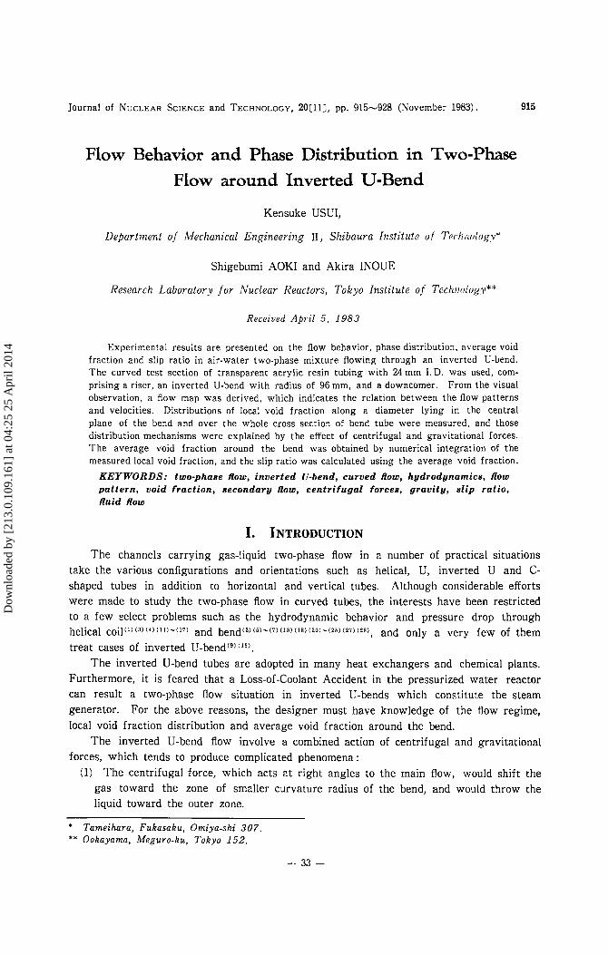
The equipment used in the present study is shown schematically in Fig. 1. The test channel, made of transparent acrylic resin tubing with an inside diameter of 24mm, comprises a riser, an inverted U-bend and a downcomer. The bend with the radius of curvature of 96 mm is used, and the riser and downcomer length are each 5.2 m long. The U-bend was made by bolting together two slabs of transparent acrylic resin in the surface of which circular groove had been machined, of accurate semi-circular cross section. The experiment was carried out with air-water two-phase flow system. In operation, the water pumped up from the storage tank @ passes through rotameters 0. The air is fed from the compressor @, passes through the air drier @, pressure reducing valve @ and rotameter; @ or orifice meters @, to the mixing chamber @, where it mixes with the water. The air- water from the test section was discharged from downcomer @ to the tank, from which the air was vented and the water was
I
0 Water tank 0 Traversing device 0 Circulation pump 0 Downcomer @,@ Rotameter @ Air compressor 8 Mixing chamber @ Air drier 0 Riser 0 Pressure reducing valve @ Bend 0 Orifice
Fig. 1 Schematic diagram of experimental equipment
- 34 -
Dow
nloa
ded
by [
213.
0.10
9.16
1] a
t 04:
25 2
5 A
pril
2014
Vol. 20, No. 11 (Nov. 1983) 917
drawn by the pump @ for recirculation. The flow rate of air and water are controlled by needle valves. The loop is operated around atmospheric pressure, at room temperature.
An resistance needle probe was used to measure the distribution of local void fraction. This is similar to that adopted in Ref. (10. The tip of the probe was made of 0.1 mm diameter stainless-steel wire whose outer surface was covered with polyester insulation of about 0.01mm thickness. The probe, mounted on a micrometer head, was arranged in a housing @ that could be rotated about the tube axis, to permit measurements of distribu- tion to be made in any direction across the tube crosssection at measuringpositions. The housing, which had a straight part of length 87mm, was inserted at the measuring posi- tions.
As experiments on distributions of local void fraction, the measurements were first carried out along a diameter lying in the central plane of the bend at eight axial stations: a station -29.2 diameters (about 700mm) upstream of the bend. (Here, the axial distance along straight tube expressed in the multiple of tube diameter has a negative sign for upstream of the bend, and has a positive sign for downstream of the bend.) For the rest of the work, local void fraction distribution across the tube cross section were obtained in detail at six sta- tions: 45, 90, 135 and 180" for the bend part, and +10D (240mm) and +20D (480mm) downstream of the bend. In the bend part, owing to symmetry with respect to the plane of the bend, measurements were made only in the half of the tube, while in the down- comer, were made over the whole cross section of the tube since the asymmetry was pre- supposed. Although the visual study of flow behavior was carried out over relatively wide range of liquid and gas flow rates, experiments on the distribution of local void fraction were performed for the bubbly and plug (or elongated bubble, slug) flow regimes at bend inlet.
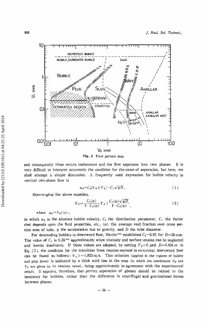
m. EXPERIMENTAL RESULTS AND DISCUSSION 1. Flow Behavior Flow patterns were classified on the basis of visual observation, from which a flow
map was derived for the inverted U-bend flow. The flow patterns which were observed in the bend were generally similar to those for the C-shaped bend f l o ~ ( ~ ~ ) ( ~ ~ ) studied pre- viously except some matters such as the ways of the gas and liquid distributions and the shape of bubbles. The map is shown in Fig. 2, indicating the form of flow observed at various combinations of superficial velocity of the liquid (V,) to that of the gas (VG).
An intriguing phenomenon observed in the present study was the separation of phases, which occurred when the flow is bubbly and plug flow regimes. The separation always commenced at about 90-100" from the bend inlet. If the flow had separated, then it was not mixed again, and went down in the downcomer in the form of the annular flow.
In downward two-phase flow through C-shaped bend(22), there were the plug flow regime region that was characterized by cyclic repetition of flow back of gas plugs, coales- cence, and expulsion of plugs at fairly regular intervals, and the stratified flow region where the gas and liquid phases flow under separation condition. These regions in the C-shaped bend are in agreement with the separation region on the flow map for the in- verted U-bend. This signifies that the two phenomena may be caused by the same mech- anism. Namely, for the low liquid flow rate, the flow in the downstream half of the bend would normally be expected to be counter-current flow (with the gas flowing upward and the liquid downward), but the gas flowing upward is prevented by the gas flow from upstream,
- 35 -
Dow
nloa
ded
by [
213.
0.10
9.16
1] a
t 04:
25 2
5 A
pril
2014
918 J. Nucl. Sci. Technol.,
10k 1 I I I I 1 1 1 1 I I I I I I l l I I I I I 1 1 1 1
:. I I
/ / 4
I I I I I I l l 1 I I I I I I I I I 1 I I I 1 1 1 1
04.0l I ' I I I ( I ' 0.l 1 10 100 VG (mrs)
Fig. 2 Flow pattern map
and consequently those occurs coalescence and the flow separates into two phases. It is very difficult to interpret accurately the condition for the onset of separation, but here, we shall attempt a simple discussion. A frequently used expression for bubble velocity in vertical two-phase flow is
uG=CO(VG+VL)+C~V'/~D. ( 1 ) Rearranging the above equation,
where UG= V G / ( C X ) , in which u G is the absolute bubble velocity, C , the distribution parameter, C, the factor that depends upon the fluid properties, etc., <a> the average void fraction over cross sec- tion area of tube, g the acceleration due to gravity, and D the tube diameter.
For descending bubbles in downward flow, Martin(le) established c,=0.93 for D=26 mm. The value of C1 is 0.35'2G) approximately when viscosity and surface tension can be neglected and inertia dominates. If these values are adopted, by setting Vc=O and D=0.024m in Eq. ( 2 ), the condition for the transition from counter-current to co-current downward flow can be found as follows : V L > -1.825 m/s. This criterion (applied in the regions of bubbly and plug flows) is indicated by a thick solid line in the map (in which the coordinates V , and vL are given by its absolute value), being approximately in agreement with the experimental result. It appears, therefore, that perfect separation of phases should be related to the buoyancy for bubbles, rather than the difference in centrifugal and gravitational forces between phases.
- 36 -
Dow
nloa
ded
by [
213.
0.10
9.16
1] a
t 04:
25 2
5 A
pril
2014
Vol. 20, No. 11 (Nov. 1983) 919
Curved channels placed in vertical plane involve the combined action of gravitational and centrifugal forces, as stated above, which would tend to produce the annular flow regime in the region of low gas flow rate as compared with upward vertical flow and horizontal straight flow as has been indicated for C-shaped bends(21)'22'. For the purpose of comparison, the typical result of the transition lines of horizontal straight flow regime"" is given in the map. For the inverted U-bend flow, it is also apparent from this flow map that the presence of bend has the effect of extending the region of annular flow toward much lower gas velocities.
In addition, it is noted that the transition line between the elongated bubble (plug) and stratified flow regimes for horizontal flow agrees with the criterion line for separation dis- cussed above.
We consider now the combined action between the centrifugal force and gravity. As- suming that the gas and liquid form two separate phases, then, the equation expressing the balance of radial force between the phase is (The details can be found in Ref. (21).),
where 8 is angle between the radius R and horizontal, U L e and U C B are average velocities, R L e and R G e the radii of curvature at the bend angle 8, p L and p C the densities for liquid and gas phases, respectively.
There is a general tendency that the average void fraction over the cross-sectional area for bend flow is higher than that for upward vertical flow, as will be shown later. But, to date the average void fraction along the bend path has not been given with a form of equation. For this reason, the relation of Eq. ( 3 ) was shown by thin solid lines for 8=90 and 135" in the flow map using the formula for average void fraction for upward vertical flow given by Smith(lg) as a first approximation. The region above the lines would correspond to the case where the liquid moves to the outside of the bend, the air shifting to the inside, and the region below the lines would give the opposite case. In curved flow, an unbalance between centrifugal force and radial pressure gradient at the side walls of the curved tube displaces high-speed fluid toward the outside of the bend along the region containing the symmetry plane, and low-speed fluid toward the inside of the bend along the side walls; as a consequence, the curved flow consists of both a main flow turn- ing about the center of curvature of bend and a twin helical flow (secondary flow). In the case where the liquid moves to the outside of the bend above the lines, the shear stress on the interface between the gas and liquid due to the secondary flow in the gas phase would tend to drive a part of the liquid on the outside of the bend toward the inside along the side walls, and therefore, the annular flow come into existence at low gas velocities.
2. Local Void Fraction Distribution The measurements of phase distribution were carried out at relatively low gas flow
rates : under conditions bubbly and plug flow at bend inlet. These flow regimes are formed by the continuous liquid phase and discontinuous gas phase dispersed as individual bubbles.
A curved flow consists of a combination between a main flow and a double secondary flow system as discussed above. Due to the density and velocity differences between the phases, then, the magnitude of centrifugal forces acting on the liquid and gas is different from one another, and thus the flow tends to become stratified. In addition, when the liquid phase is continuous and the gas is discontinuous as bubbly flow, the bubble in the
- 37 -
Dow
nloa
ded
by [
213.
0.10
9.16
1] a
t 04:
25 2
5 A
pril
2014
920
cj
0.5
o_1 INSIDE
+1 OUTSIDE
o, ~-=-=::!==~ 90'
0 """-'""---'------'"" 1r---~--~
9 ~==~===3=0~'
0.5 _______ ...--"\
0 -1
INSIDE
,-, __ .., ______ ,.. ___ .. \
0 +1 OUTSIDE
). Nucl. Sci. Techno/.,
0.5 : I I I I ,
0, .1 ~1=50=,===,:-:-,. r::-:_::-_:-: __ :-::_:-:_ -=-=-~-~
0.5
' '
0 ' 1 120'
, ,
0 '--~.::..:.._.....__ __ _J
1.----~--~
60'
0.5 ... ~ ... _ ~- .. ' ' '
9 ~===!:==0::::;'
0.5 ,' ..... \ ... , \
9 ~! =·=-::=::;:==·--=-' :::::'1 -29.2D
0,5
,_,,-- ..... __ _
OL.-__ ,__ _ ___J
-1 0 INSIDE
+1 OUTSIDE
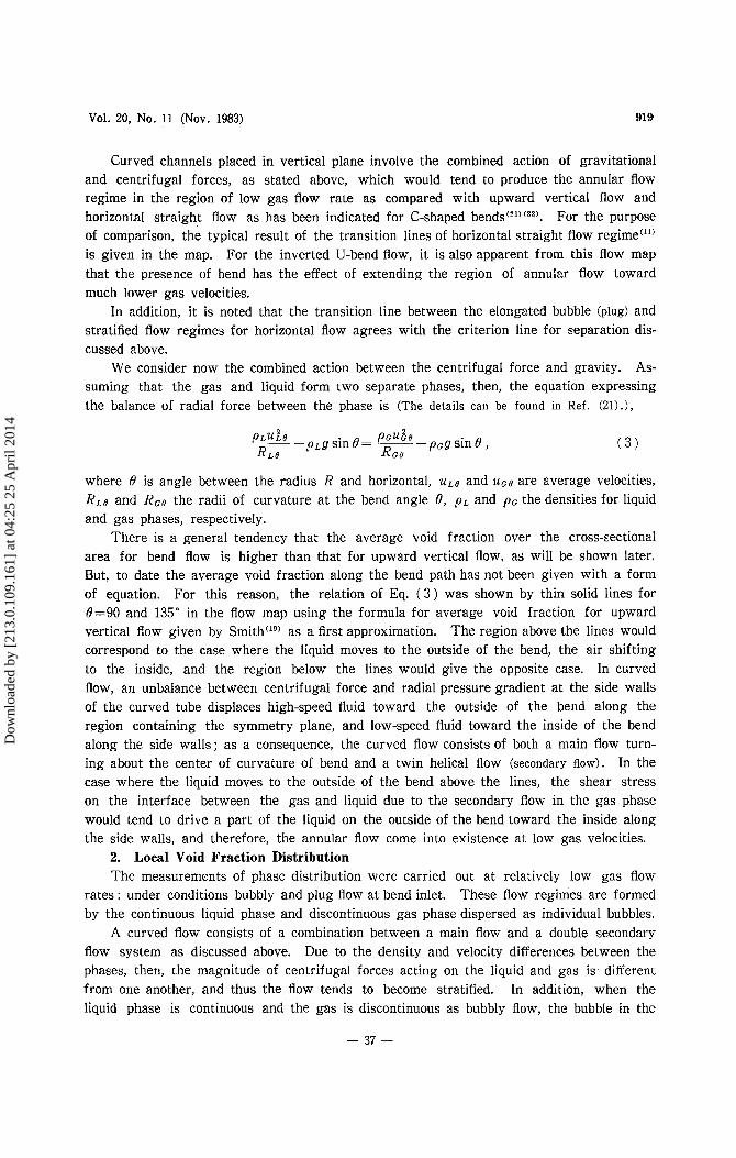
(a) VL=!.Om!s; ...... , Vc=0.131m/s, (b) VL=0.516m/s; ...... , Vc=0.124m/s, (c) VL=0.184m/s, ...... , Vc=O.l32:n/s -: 0.261, -·-: 0.780 -: C.244, -·-: 0.756
Fig. 3 Phase distribution along diameter lying in plane of bend
-38-
Dow
nloa
ded
by [
213.
0.10
9.16
1] a
t 04:
25 2
5 A
pril
2014
Vol. 20, No. 11 (Nov. 1983) 921
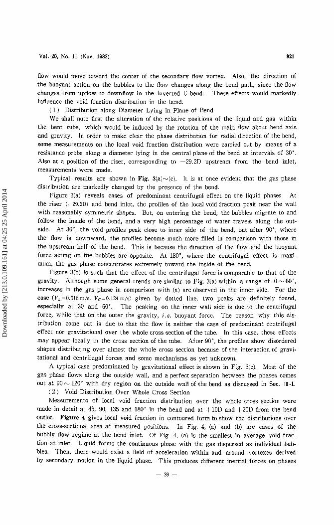
flow would move toward the center of the secondary flow vortex. Also, the direction of the buoyant action on the bubbles to the flow changes along the bend path, since the flow changes from upflow to downflow in the inverted U-bend. These effects would markedly influence the void fraction distribution in the bend.
( 1 ) Distribution along Diameter Lying in Plane of Bend We shall note first the alteration of the relative positions of the liquid and gas within
the bent tube, which would be induced by the rotation of the main flow about bend axis and gravity. In order to make clear the phase distribution for radial direction of the bend, some measurements on the local void fraction distribution were carried out by means of a resistance probe along a diameter lying in the central plane of the bend at intervals of 30'. Also at a position of the riser, corresponding to -29.2D upstream from the bend inlet, measurements were made.
Typical results are shown in Fig. 3(a)-(c). It is at once evident that the gas phase distribution are markedly changed by the presence of the bend.
Figure 3(a) reveals cases of predominant centrifugal effect on the liquid phases At the riser (-29.2D) and bend inlet, the profiles of the local void fraction peak near the wall with reasonably symmetric shapes. But, on entering the bend, the bubbles migrate to and follow the inside of the bend, and a very high percentage of water travels along the out- side. At 30", the void profiles peak close to inner side of the bend, but after go", where the flow is downward, the profiles become much more filled in comparison with those in the upstream half of the bend. This is because the direction of the flow and the buoyant force acting on the bubbles are opposite. At 180", where the centrifugal effect is maxi- mum, the gas phase concentrates extremely toward the inside of the bend.
Figure 3(b) is such that the effect of the centrifugal force is comparable to that of the gravity. Although some general trends are similar to Fig. 3(a) within a range of 0 - 60", increases in the gas phase in comparison with (a) are observed in the inner side. For the case (VL=0.516 m/s, vG=0.124 m/s) given by dotted line, two peaks are definitely found, especially a t 30 and 60". The peaking on the inner wall side is due to the centrifugal force, while that on the outer the gravity, i . e . buoyant force. The reason why this dis- tribution come out is due to that the flow is neither the case of predominant centrifugal effect nor gravitational over the whole cross section of the tube. In this case, these effects may appear locally in the cross section of the tube. After go", the profiles show disordered shapes distributing over almost the whole cross section because of the interaction of gravi- tational and centrifugal forces and some mechanisms as yet unknown.
A typical case predominated by gravitational effect is shown in Fig. 3(c). Most of the gas phase flows along the outside wall, and a perfect separation between the phases comes out a t 90 N 120" with dry region on the outside wall of the bend as discussed in Sec. HI-1.
( 2 ) Void Distribution Over Whole Cross Section Measurements of local void fraction distribution over the whole cross section were
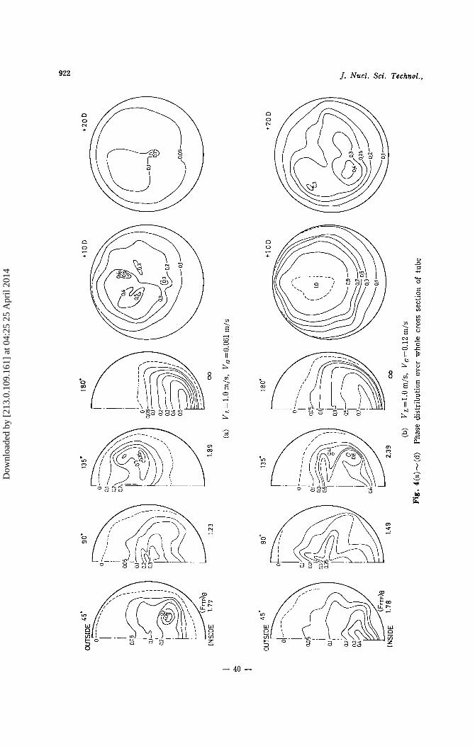
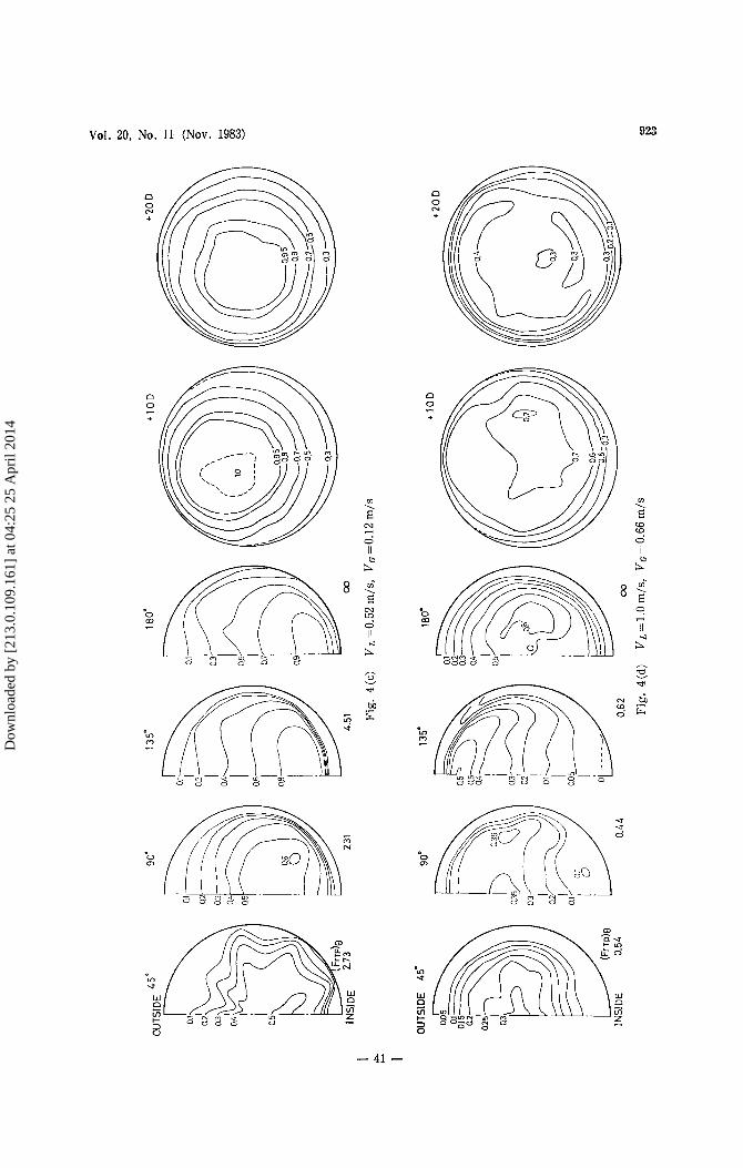
made in detail at 45, 90, 135 and 180" in the bend and at +10D and +20D from the bend outlet. Figure 4 gives local void fraction in contoured form to show the distributions over the cross-sectional area at measured positions. In Fig. 4, (a) and (b) are cases of the bubbly flow regime at the bend inlet. Of Fig. 4, (a) is the smallest in average void frac- tion at inlet. Liquid forms the continuous phase with the gas dispersed as individual bub- bles. Then, there would exist a field of acceleration within and around vortexes derived by secondary motion in the liquid phase. This produces different inertial forces on phases
- 39 -
Dow
nloa
ded
by [
213.
0.10
9.16
1] a
t 04:
25 2
5 A
pril
2014
922 J. Nucl. Sci. Technol.,
rn ‘ E 3 W
8 s”
II
rn \ E 9 II b
3
Ll
n
v m
- 40 -
Dow
nloa
ded
by [
213.
0.10
9.16
1] a
t 04:
25 2
5 A
pril
2014
Vol. 20, No. 11 (Nov. 1983) 923
m 1 E
ti .- l&
- 41 -
Dow
nloa
ded
by [
213.
0.10
9.16
1] a
t 04:
25 2
5 A
pril
2014
924 J. Nucl. Sci. Technol.,
with different densities. It is noticeable that, at the 45" position, bubbles concentrate toward the center of vortexes which occur by the inner side of the bend. Although this tendency goes down once at go", it recover again at 135", shifting the position of the highest void fraction toward the outer side of the bend. In the case of single-phase flow, the intensity of secondary flow is the highest at about 30-40°(24) and lower for the down- stream. As the average void fraction in tube increases ( ( a ) < (b)) , the high concentration position of bubbles derived by the secondary motion tends to shift downstream and the degree of concentration weaken, since the degree of continuity of liquid phase decreases with increasing gas flow rate. Thus, in two-phase flow the presence of bubbles would clearly have an additional effect on the intensity of the secondary motion and the positions of bubble concentration.
At 180" (bend outlet), the influence of the secondary motion is no longer apparent and all the profiles show a similar tendency irrespective of upstream different distributions, possessing a very higher value close to the inner side of the bend. When 8=180", the gravitational terms in Eq. ( 3 ) disappear, and if VLe=VGe and RLe+RGe, and since pL>pc , Eq. ( 3 ) becomes
This equation means that the centrifugal effect acting on the liquid phase against that on the gas phase governs the flow. For this reason, the liquid flows along the outer side of the bend and the gas the inner side of the bend. Sometimes, this effect leads to the formation of a cavity in the vicinity of +10D downstream of the bend (Fig. 4(b)) .
Figure 4(c) and (d) are for the plug flow. In Fig. 4(c), the effect of gravity is sub- stantial as compared with the centrifugal force so that the positions of the liquid and gas differ from those for Fig. 4(a) and (b). As the average void fraction is higher and the degree of continuity of liquid phase is much poor, the effect of secondary flow is smaller and the behavior of bubble concentration by secondary motion is not clear, while the maxi- mum in the void profiles lies near the outer surface at 135" by means of the action of gravity.
Figure 4(d) shows the case near the transition to plug and slug (or froth) flow, having the average void fraction of about two times higher than that at Fig. 4(c). Here, the centrifugal action is predominant like (a) and (b), and so the region of high void fraction lies close to the inner side of the bend. At 180", the void fraction near the inner wall is about unity, and at +10D the cavity was formed being analogous to the case of Fig. 4(b). At +20D, the cavity vanished and it can be seen that the developed downward two-phase flow come to be formed as the flow proceeds.
The interaction of the centrifugal force and gravity for the main flow turning about the bend axis has been discussed by Banerjee et u L . ' ~ ) , Gardner & Neller(*), Oshinowo &
From Usui et al. (21)(22), this interaction has been explained approximately with a Froude number defined as
and Usui et a1.(21)(22), qualitatively.
where, (FrTp)B indicates the ratio of centrifugal force to gravity of radial direction of bend. From this value, the relative positions of the liquid and gas for the radial direction of the
- 42 -
Dow
nloa
ded
by [
213.
0.10
9.16
1] a
t 04:
25 2
5 A
pril
2014
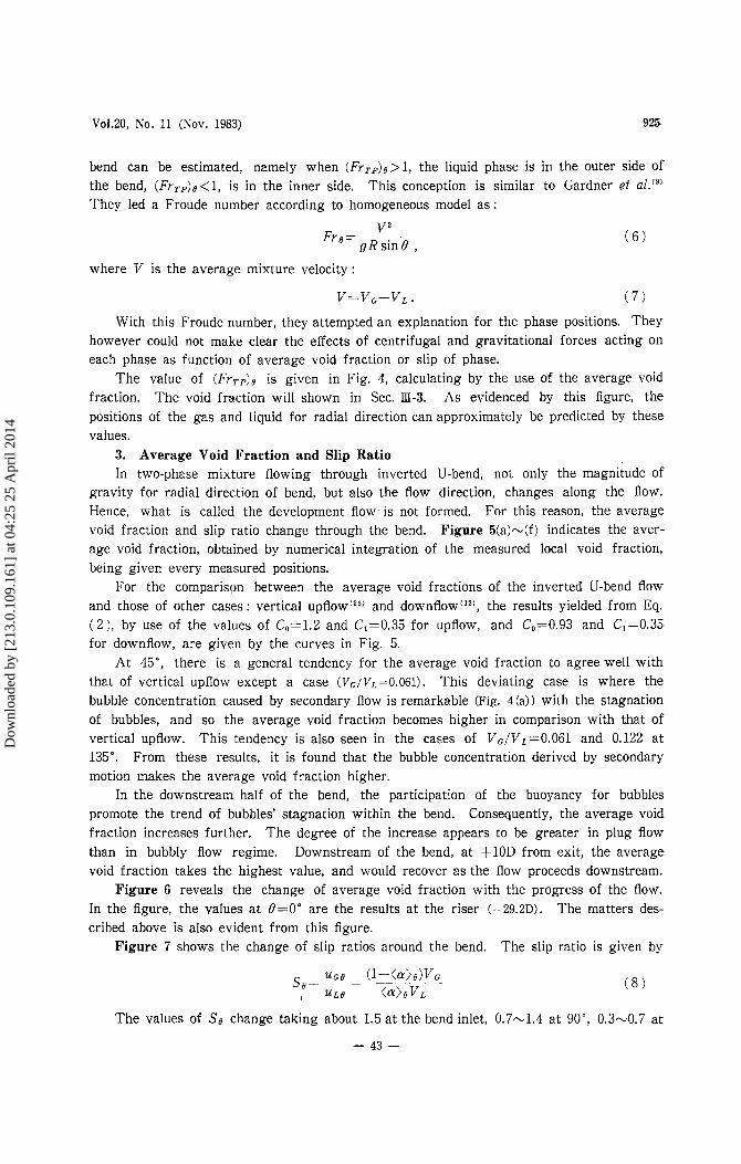
V01.20, No. 11 (Nov. 1983) 925
bend can be estimated, namely when (FYTp)e>l, the liquid phase is in the outer side of the bend, (FrrP)@<1, is in the inner side. This conception is similar to Gardner et d."' They led a Froude number according to homogeneous model a s :
where V is the average mixture velocity:
V=Vc+VL. ( 7 )
With this Froude number, they attempted an explanation for the phase positions. They however could not make clear the effects of centrifugal and gravitational forces acting on each phase as function of average void fraction or slip of phase.
The value of (FrTP)@ is given in Fig. 4, calculating by the use of the average void fraction. The void fraction will shown in Sec. IU-3. As evidenced by this figure, the positions of the gas and liquid for radial direction can approximately be predicted by these values.
3. Average Void Fraction and Slip Ratio In two-phase mixture flowing through inverted U-bend, not only the magnitude of
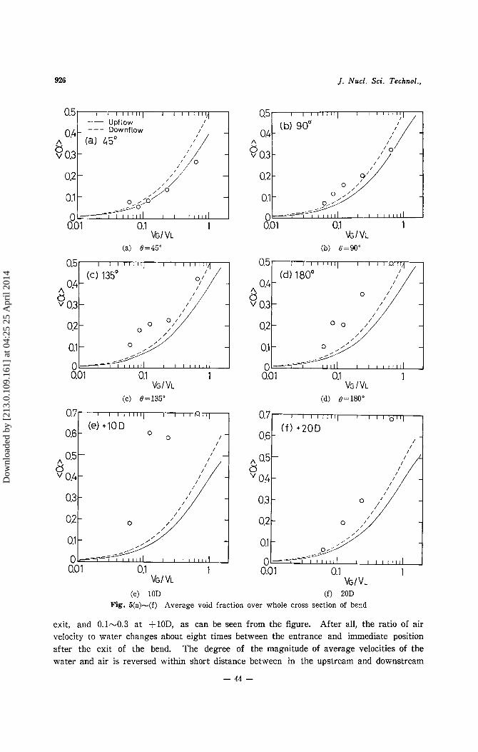
gravity for radial direction of bend, but also the flow direction, changes along the flow. Hence, what is called the development flow is not formed. For this reason, the average void fraction and slip ratio change through the bend. Figure 5(a)-(f) indicates the aver- age void fraction, obtained by numerical integration of the measured local void fraction, being given every measured positions.
For the comparison between the average void fractions of the inverted U-bend flow and those of other cases: vertical ~ p f l o w ' ~ ~ ) and downflow[l2), the results yielded from Eq. (21, by use of the values of C,,=1.2 and C1=0.35 for upflow, and C0=0.93 and C1=0.35 for downflow, are given by the curves in Fig. 5.
At 45", there is a general tendency for the average void fraction to agree well with that of vertical upflow except a case (Vc/VL=0.061). This deviating case is where the bubble concentration caused by secondary flow is remarkable (Fig. 4(a)) with the stagnation of bubbles, and so the average void fraction becomes higher in comparison with that of vertical upflow. This tendency is also seen in the cases of Vc/VL=0.061 and 0.122 at 135". From these results, it is found that the bubble concentration derived by secondary motion makes the average void fraction higher.
In the downstream half of the bend, the participation of the buoyancy for bubbles promote the trend of bubbles' stagnation within the bend. Consequently, the average void fraction increases further. The degree of the increase appears to be greater in plug flow than in bubbly flow regime. Downstream of the bend, a t +10D from exit, the average void fraction takes the highest value, and would recover as the flow proceeds downstream.
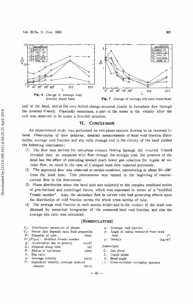
Figure 6 reveals the change of average void fraction with the progress of the flow. In the figure, the values a t 8=0" are the results a t the riser (-29.2D). The matters des- cribed above is also evident from this figure.
The slip ratio is given by Figure 7 shows the change of slip ratios around the bend.
The values of SO change taking about 1.5 a t the bend inlet, 0.7-1.4 a t go", 0.3-0.7 a t
- 43 -
Dow
nloa
ded
by [
213.
0.10
9.16
1] a
t 04:
25 2
5 A
pril
2014
926
0.5
0.4 2 "031 02
0.1
0
J. Nucl. Sci. Technol..
I 1 I 1 1 I I I I I I I I I l l 1
(C) 135" - /
_I I - , , -
- -. I I I l l l l I I I I I 1 1 1 1
0.5 I I I 1 1 1 1 1 ~ I I I I I I "/I - Upflow I
Downflow I - _ -
E! A 0.4- 0.3 - (a) 450
.'I 0 0.2 - -
,>o
0 I 1 I I l l 1 1 I I 1 1 1 1 1 1
0.01 0.1 1
'/ 0s - _o,p
vG/ VL
(a) 8=45"
0.5 I I I 1 1 1 1 1 ~ I I I I I I "/I - Upflow I
Downflow A 0'4[ (iY-45" E! 0.3
0.21 />' -1
vG/ VL
(a) 8=45"
vG/ VL
(c) 8=135"
0.7 R '11
0 0.6 0
V 0.4 9
0.3 1
. / - I /
0.0 1 0.1 1 VG/ VL
(e) 10D
(b) C=90"
0.4
V 0.3 a
601 0.1 1 VG I VL
(d) 8=180"
0.7 I I I I '0 I l l
( f ) +20D 0.6 - /
I I
cs 0.4-
I I I I I I I I I 0.0 1 0.1 1
v G / v L (f) 20D
Fig. 5(a)-(f) Average void fraction over whole cross section of bend
exit, and 0.1-0.3 at +lOD, as can be seen from the figure. After all, the ratio of air velocity to water changes about eight times between the entrance and immediate position after the exit of the bend. The degree of the magnitude of average velocities of the water and air is reversed within short distance between in the upstream and downstream
- 44 -
Dow
nloa
ded
by [
213.
0.10
9.16
1] a
t 04:
25 2
5 A
pril
2014
Vol. 20,No. 11 (Nov. 1983) 927
1.0
a " 0.5
0 0" 45" 90" 13p 180' 10 D 20 D
L Fig. 6 Change of average void
2
(?I
1
0 0" 45' 90" 135' 180" 10 D 20 D
L fraction round bend Fig. 7 Change of average slip ratio round bend
half of the bend, and so the very radical change occurred clearly in two-phase flow through the inverted U-bend. Especially sometimes, a part of the water in the vicinity after the exit was observed to be under a free-fall situation.
VI. CONCLUSION An experimental study was performed on two-phase mixture flowing in an inverted U-
bend. Observation of flow behavior, detailed measurements of local void fraction distri- bution, average void fraction and slip ratio through and in the vicinity of the bend yielded the following conclusions :
(1) The flow map derived for two-phase mixture flowing through the inverted U-bend revealed that, as compared with flow through the straight tube, the presence of the bend has the effect of extending toward much lower gas velocities the region of an- nular flow, as noted in the case of C-shaped bend flow reported previously.
(2) The separated flow was observed at certain condition, commencing at about 90-100" from the bend inlet. This phenomenon was related to the beginning of counter- current flow in the downcomer.
(3) Phase distribution about the bend axis was subjected to the complex combined action of gravitational and centrifugal forces, which was expressed in terms of a "modified Froude number". Also, the secondary flow in curved tube had governing effects upon the distribution of void fraction across the whole cross section of tube.
(4) The average void fraction at each station within and in the vicinity of the bend was obtained by numerical integration of the measured local void fraction, and also the average slip ratio was calculated.
[NOMENCLATURE]
Co : Distribution parameter of phases C,: Factor that depends upon fluid properties
Fr, ( F T T P ) : Modified Froude number D : Diameter of tube (mm)
g : Acceleration due to gravity (m/s2) L : Distance along tube (m) R : Radius of curvature (mm) S : Slip ratio u : Average velocity W s ) V : Superficial velocity, average mixture
velocity (m/s)
a : Average void fraction 0 : Angle of radius measured from bend
inlet (") p : Density (kg/m3)
(Subscripts) G : Gas phase L : Liquid phase 8 : Bend angle
( ) : Cross-sectional averaging operator
- 95 -
Dow
nloa
ded
by [
213.
0.10
9.16
1] a
t 04:
25 2
5 A
pril
2014
928 ]. Nucl. Sci. Technol.,
ACKNOWLEDGMENT
The authors would like to thank Prof. K. Sato and Prof. Y. Oguchi for the advice and encouragement, and Mr. T. Okuno, Mr. Y. Wada, Mr. K. Higuchi and Mr. T. Amano for the assistance during the progress of this study.
-REFERENCES-
(1) AKAGAWA, K., et al.: Trans. ]SME, 36, 1712 (1970). (2) ALVES, G. E.: Chern. Eng. Prog., 50[9], 449 (1954). (3) BANERJEE, S., et al.: AIChE ]., 13[1], 189 (1967). (4) BANERJEE, S., et al.: Can.]. Chern. Eng., 47, 445 (1969). (5) CHISHOLM, D. : Eng. Boil. House Rev., 82[8], 235 (1967). (6) FARUKHI, M.N., PARKER, J.D.: Proc. 5th Int. Heat Transfer Conf., B5.5, 205 (1974). (7) FITZSIMMONS, D. E. : HW-80970, Rev. 1, (1964). (8) GARDNER, G.C., NELLER, P.H.: Proc. /nsf. Mech. Eng., 184(Pt.3C), 93 (1969-70). (9) HoANG, k., DAVIS, M. R.: Int. ]. Multiphase Flow, 6, 267 (1980). ~o) INOUE, A., et al.: Trans. ]SME, 42[360], 2521 (1976). (11) MANDHA:-IE, J. M., et al.: Int. ]. Multiphase Flow, 1, 537 (1974). (1~ MARTIN, C. S.: ]. Fluids Eng., 715 (1976). (13) OsHINowo, T., CHARLES, M. E.: Can. ]. Chern. Eng., 52, 25 (1974). (14) OwHADI, A., et al.: Int.]. Heat Mass Transfer, 11, 1779 (1968). (15) KozEKI, M., et al.:]. ]SME, 73[615], 538 (1970). (16) RIPPEL, G. R., et al.: Ind. Eng. Chern. Process. Design Develop., 5, 32 (1966). (17) SATO, Y., et al.: ]. Chern. Eng., 34, 98 (1970). (18) SEKOGUCHI, K., et al.: Trans. ]SME, 35[279], 2227 (1969). (19) SMITH, S. L.: Proc. Inst. Mech. Eng., 184(Pt. 1)-36 647 (1969-70). (20) Usm, K., et al.: Pre print 9th japan Heat Transfer Symp., 73 (1972). (21) Usm, K., et al.: ]. Nucl. Sci. Techno!., 17[12], 875 (1980). (22) Usm, K., et al.: ibid., 18[3], 179 (1981). (23) Usm, K.: Res. Rep. Shibaura Inst. Techno!. Natural Sci. Eng., 25[2], 12 (1981). (24) idem: ibid., 26[1], 25 (1982). (25) idem: ibid., 26[2], 14 (1982). (26) WALLIS, G. B. : "One-dimensional Two-phase Flow", 285 (1969), McGraw-Hill. (27) ZAHN, W. R. : Trans. ASME, ]. Heat Transfer, 86, 417 (1964). (28) idem: Trans. ASH RAE, 72[1], 82 (1966).
-46-
Dow
nloa
ded
by [
213.
0.10
9.16
1] a
t 04:
25 2
5 A
pril
2014
![Two Phase Flow Systems. - Aquatherm · Since a Waterfall Flow reduces the flow and a Two Phase Flow creates a lower rate [l/s] than originally calculated, based on a single-phase](https://img.pdfslide.net/doc/110x75/5d67411288c993b2178b622a/two-phase-flow-systems-since-a-waterfall-flow-reduces-the-flow-and-a-two.jpg)