Embed Size (px)
Citation preview
Instructions-Parts
Flow Control Modules 3A2097B
EN
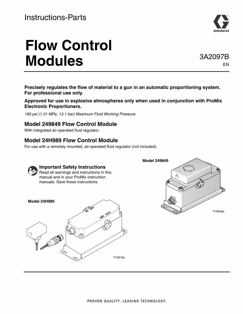
Precisely regulates the flow of material to a gun in an automatic proportioning system. For professional use only.
Approved for use in explosive atmospheres only when used in conjunction with ProMix Electronic Proportioners.
190 psi (1.31 MPa, 13.1 bar) Maximum Fluid Working Pressure
Model 249849 Flow Control Module With integrated air-operated fluid regulator.
Model 24H989 Flow Control ModuleFor use with a remotely mounted, air-operated fluid regulator (not included).
TI18058a
Important Safety InstructionsRead all warnings and instructions in this manual and in your ProMix instruction manuals. Save these instructions.
TI18016a
Model 249849
Model 24H989
Related Manuals
2 3A2097B
Related ManualsProMix Manuals in English
Grounding
Ground all components in your system, as explained in your ProMix Installation manual.
Ground a remote fluid regulator (used with Model 24H989 only) by connection to a properly grounded fluid hose.
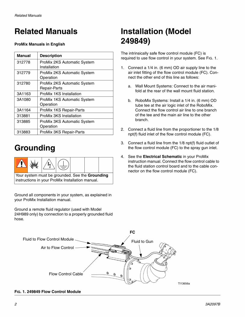
Installation (Model 249849)The intrinsically safe flow control module (FC) is required to use flow control in your system. See FIG. 1.
1. Connect a 1/4 in. (6 mm) OD air supply line to the air inlet fitting of the flow control module (FC). Con-nect the other end of this line as follows:
a. Wall Mount Systems: Connect to the air mani-fold at the rear of the wall mount fluid station.
b. RoboMix Systems: Install a 1/4 in. (6 mm) OD tube tee at the air logic inlet of the RoboMix. Connect the flow control air line to one branch of the tee and the main air line to the other branch.
2. Connect a fluid line from the proportioner to the 1/8 npt(f) fluid inlet of the flow control module (FC).
3. Connect a fluid line from the 1/8 npt(f) fluid outlet of the flow control module (FC) to the spray gun inlet.
4. See the Electrical Schematic in your ProMix instruction manual. Connect the flow control cable to the fluid station control board and to the cable con-nector on the flow control module (FC).
Manual Description
312778 ProMix 2KS Automatic System Installation
312779 ProMix 2KS Automatic System Operation
312780 ProMix 2KS Automatic System Repair-Parts
3A1163 ProMix 1KS Installation3A1080 ProMix 1KS Automatic System
Operation3A1164 ProMix 1KS Repair-Parts313881 ProMix 3KS Installation313885 ProMix 3KS Automatic System
Operation313883 ProMix 3KS Repair-Parts
Your system must be grounded. See the Grounding instructions in your ProMix Installation manual.
FIG. 1. 249849 Flow Control Module
FC
Fluid to Flow Control Module
Air to Flow Control
Fluid to Gun
Flow Control Cable
TI13656a
Installation (Model 24H989)
3A2097B 3
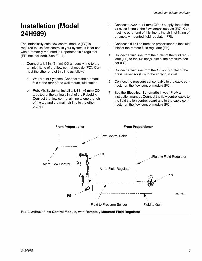
Installation (Model 24H989)The intrinsically safe flow control module (FC) is required to use flow control in your system. It is for use with a remotely mounted, air-operated fluid regulator (FR, not included). See FIG. 2.
1. Connect a 1/4 in. (6 mm) OD air supply line to the air inlet fitting of the flow control module (FC). Con-nect the other end of this line as follows:
a. Wall Mount Systems: Connect to the air mani-fold at the rear of the wall mount fluid station.
b. RoboMix Systems: Install a 1/4 in. (6 mm) OD tube tee at the air logic inlet of the RoboMix. Connect the flow control air line to one branch of the tee and the main air line to the other branch.
2. Connect a 5/32 in. (4 mm) OD air supply line to the air outlet fitting of the flow control module (FC). Con-nect the other end of this line to the air inlet fitting of a remotely mounted fluid regulator (FR).
3. Connect a fluid line from the proportioner to the fluid inlet of the remote fluid regulator (FR).
4. Connect a fluid line from the outlet of the fluid regu-lator (FR) to the 1/8 npt(f) inlet of the pressure sen-sor (PS).
5. Connect a fluid line from the 1/8 npt(f) outlet of the pressure sensor (PS) to the spray gun inlet.
6. Connect the pressure sensor cable to the cable con-nector on the flow control module (FC).
7. See the Electrical Schematic in your ProMix instruction manual. Connect the flow control cable to the fluid station control board and to the cable con-nector on the flow control module (FC).
FIG. 2. 24H989 Flow Control Module, with Remotely Mounted Fluid Regulator
262376_1
FC
FR
Fluid to Pressure Sensor
Air to Flow ControlAir to Fluid Regulator
Fluid to Fluid Regulator
Fluid to Gun
Flow Control Cable
PS
From Proportioner From Proportioner
Service
4 3A2097B
Service
Before Servicing
1. Flush system and follow Pressure Relief Proce-dure in your ProMix Repair-Parts manual.
2. Close main air shutoff valve on air supply line and on ProMix.
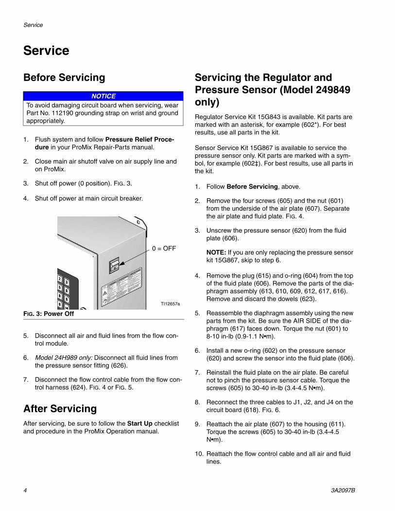
3. Shut off power (0 position). FIG. 3.
4. Shut off power at main circuit breaker.
5. Disconnect all air and fluid lines from the flow con-trol module.
6. Model 24H989 only: Disconnect all fluid lines from the pressure sensor fitting (626).
7. Disconnect the flow control cable from the flow con-trol harness (624). FIG. 4 or FIG. 5.
After ServicingAfter servicing, be sure to follow the Start Up checklist and procedure in the ProMix Operation manual.
Servicing the Regulator and Pressure Sensor (Model 249849 only)Regulator Service Kit 15G843 is available. Kit parts are marked with an asterisk, for example (602*). For best results, use all parts in the kit.
Sensor Service Kit 15G867 is available to service the pressure sensor only. Kit parts are marked with a sym-bol, for example (602‡). For best results, use all parts in the kit.
1. Follow Before Servicing, above.
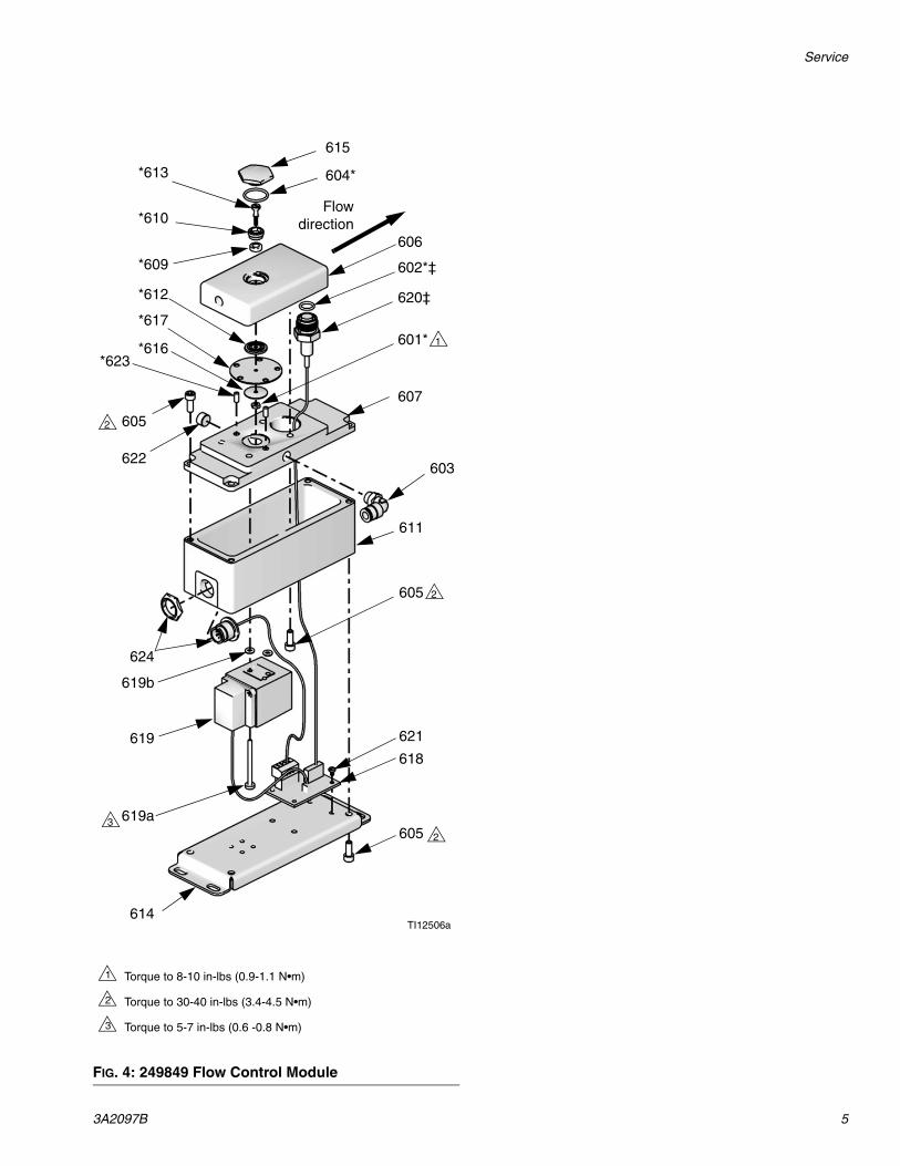
2. Remove the four screws (605) and the nut (601) from the underside of the air plate (607). Separate the air plate and fluid plate. FIG. 4.
3. Unscrew the pressure sensor (620) from the fluid plate (606).
NOTE: If you are only replacing the pressure sensor kit 15G867, skip to step 6.
4. Remove the plug (615) and o-ring (604) from the top of the fluid plate (606). Remove the parts of the dia-phragm assembly (613, 610, 609, 612, 617, 616). Remove and discard the dowels (623).
5. Reassemble the diaphragm assembly using the new parts from the kit. Be sure the AIR SIDE of the dia-phragm (617) faces down. Torque the nut (601) to 8-10 in-lb (0.9-1.1 N•m).
6. Install a new o-ring (602) on the pressure sensor (620) and screw the sensor into the fluid plate (606).
7. Reinstall the fluid plate on the air plate. Be careful not to pinch the pressure sensor cable. Torque the screws (605) to 30-40 in-lb (3.4-4.5 N•m).
8. Reconnect the three cables to J1, J2, and J4 on the circuit board (618). FIG. 6.
9. Reattach the air plate (607) to the housing (611). Torque the screws (605) to 30-40 in-lb (3.4-4.5 N•m).
10. Reattach the flow control cable and all air and fluid lines.
NOTICETo avoid damaging circuit board when servicing, wear Part No. 112190 grounding strap on wrist and ground appropriately.
FIG. 3: Power Off
0 = OFF
TI12657a
Service
3A2097B 5
FIG. 4: 249849 Flow Control Module
604*
606
620‡
607
603
605
619618
621
605
614
601*
624
622
605
*623
*613
*610
*609
*612
*617
*616
611
615
TI12506a
602*‡
619a
619b
Flowdirection
1
2
2
3
2
Torque to 8-10 in-lbs (0.9-1.1 N•m)
Torque to 30-40 in-lbs (3.4-4.5 N•m)
Torque to 5-7 in-lbs (0.6 -0.8 N•m)
1
2
3
Service
6 3A2097B
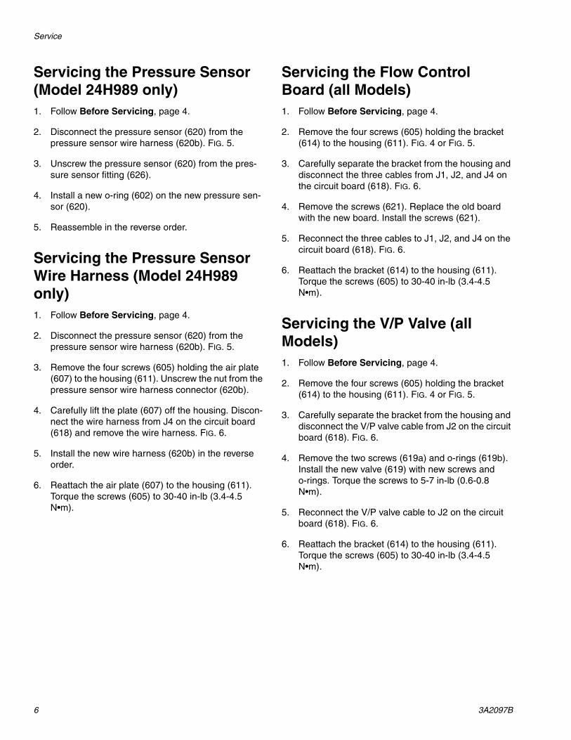
Servicing the Pressure Sensor (Model 24H989 only)1. Follow Before Servicing, page 4.
2. Disconnect the pressure sensor (620) from the pressure sensor wire harness (620b). FIG. 5.
3. Unscrew the pressure sensor (620) from the pres-sure sensor fitting (626).
4. Install a new o-ring (602) on the new pressure sen-sor (620).
5. Reassemble in the reverse order.
Servicing the Pressure Sensor Wire Harness (Model 24H989 only)1. Follow Before Servicing, page 4.
2. Disconnect the pressure sensor (620) from the pressure sensor wire harness (620b). FIG. 5.
3. Remove the four screws (605) holding the air plate (607) to the housing (611). Unscrew the nut from the pressure sensor wire harness connector (620b).
4. Carefully lift the plate (607) off the housing. Discon-nect the wire harness from J4 on the circuit board (618) and remove the wire harness. FIG. 6.
5. Install the new wire harness (620b) in the reverse order.
6. Reattach the air plate (607) to the housing (611). Torque the screws (605) to 30-40 in-lb (3.4-4.5 N•m).
Servicing the Flow Control Board (all Models)1. Follow Before Servicing, page 4.
2. Remove the four screws (605) holding the bracket (614) to the housing (611). FIG. 4 or FIG. 5.
3. Carefully separate the bracket from the housing and disconnect the three cables from J1, J2, and J4 on the circuit board (618). FIG. 6.
4. Remove the screws (621). Replace the old board with the new board. Install the screws (621).
5. Reconnect the three cables to J1, J2, and J4 on the circuit board (618). FIG. 6.
6. Reattach the bracket (614) to the housing (611). Torque the screws (605) to 30-40 in-lb (3.4-4.5 N•m).
Servicing the V/P Valve (all Models)1. Follow Before Servicing, page 4.
2. Remove the four screws (605) holding the bracket (614) to the housing (611). FIG. 4 or FIG. 5.
3. Carefully separate the bracket from the housing and disconnect the V/P valve cable from J2 on the circuit board (618). FIG. 6.
4. Remove the two screws (619a) and o-rings (619b). Install the new valve (619) with new screws and o-rings. Torque the screws to 5-7 in-lb (0.6-0.8 N•m).
5. Reconnect the V/P valve cable to J2 on the circuit board (618). FIG. 6.
6. Reattach the bracket (614) to the housing (611). Torque the screws (605) to 30-40 in-lb (3.4-4.5 N•m).
Service
3A2097B 7
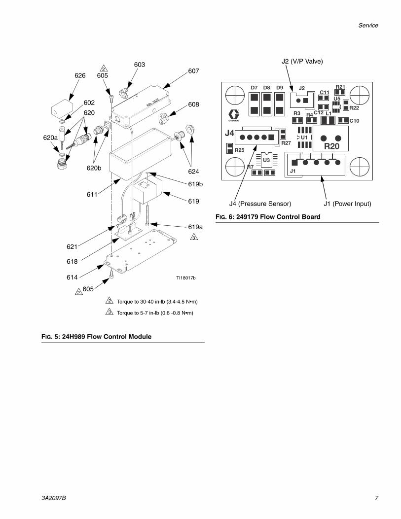
FIG. 5: 24H989 Flow Control Module
607
620608
619
618
621
605
614
620b
603
602
611
605
619a
619b
626
624
620a
2
3
Torque to 30-40 in-lb (3.4-4.5 N•m)
Torque to 5-7 in-lb (0.6 -0.8 N•m)
2
3
2
TI18017b
FIG. 6: 249179 Flow Control Board
R20
J1
D7 D8 D9 J2 R21C11
U5
R22L1
C10
C12R4R3
U1R27
R25
U3R7
J4
J2 (V/P Valve)
J1 (Power Input)J4 (Pressure Sensor)
Parts
8 3A2097B
Parts
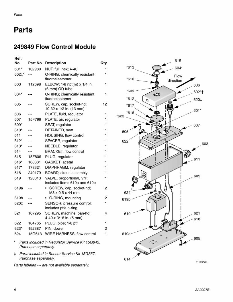
249849 Flow Control Module
* Parts included in Regulator Service Kit 15G843. Purchase separately.
‡ Parts included in Sensor Service Kit 15G867. Purchase separately.
Parts labeled --- are not available separately.
Ref. No. Part No. Description Qty
601* 102980 NUT, full, hex; 4-40 1602‡* --- O-RING; chemically resistant
fluoroelastomer1
603 112698 ELBOW; 1/8 npt(m) x 1/4 in. (6 mm) OD tube
1
604* --- O-RING; chemically resistant fluoroelastomer
1
605 --- SCREW, cap, socket-hd; 10-32 x 1/2 in. (13 mm)
12
606 --- PLATE, fluid, regulator 1607 15F799 PLATE, air, regulator 1609* --- SEAT, regulator 1610* --- RETAINER, seat 1611 --- HOUSING, flow control 1612* --- SPACER, regulator 1613* --- NEEDLE, regulator 1614 --- BRACKET, flow control 1615 15F806 PLUG, regulator 1616* 168881 GASKET; acetal 1617* 178321 DIAPHRAGM, regulator 1618 249179 BOARD, circuit assembly 1619 120013 VALVE, proportional, V/P;
includes items 619a and 619b1
619a --- • SCREW, cap, socket-hd; M3 x 0.5 x 44 mm
2
619b --- • O-RING, mounting 2620‡ --- SENSOR, pressure control;
includes ptfe o-ring1
621 107295 SCREW, machine, pan-hd; 4-40 x 3/16 in. (5 mm)
4
622 104765 PLUG, pipe; 1/8 ptf 1623* 192387 PIN, dowel 2624 15G613 WIRE HARNESS, flow control 1
604*
606
620‡
607
603
605
619618
621
605
614
601*
624
622
605
*623
*613
*610
*609
*612
*617
*616
611
615
TI12506a
602*‡
619a
619b
Flowdirection
Parts
3A2097B 9
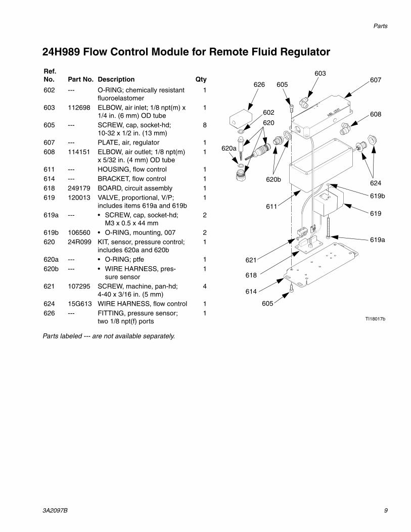
24H989 Flow Control Module for Remote Fluid Regulator
Parts labeled --- are not available separately.
Ref. No. Part No. Description Qty
602 --- O-RING; chemically resistant fluoroelastomer
1
603 112698 ELBOW, air inlet; 1/8 npt(m) x 1/4 in. (6 mm) OD tube
1
605 --- SCREW, cap, socket-hd; 10-32 x 1/2 in. (13 mm)
8
607 --- PLATE, air, regulator 1608 114151 ELBOW, air outlet; 1/8 npt(m)
x 5/32 in. (4 mm) OD tube1
611 --- HOUSING, flow control 1614 --- BRACKET, flow control 1618 249179 BOARD, circuit assembly 1619 120013 VALVE, proportional, V/P;
includes items 619a and 619b1
619a --- • SCREW, cap, socket-hd; M3 x 0.5 x 44 mm
2
619b 106560 • O-RING, mounting, 007 2620 24R099 KIT, sensor, pressure control;
includes 620a and 620b1
620a --- • O-RING; ptfe 1620b --- • WIRE HARNESS, pres-
sure sensor1
621 107295 SCREW, machine, pan-hd; 4-40 x 3/16 in. (5 mm)
4
624 15G613 WIRE HARNESS, flow control 1626 --- FITTING, pressure sensor;
two 1/8 npt(f) ports1
607
620608
619
618
621
605
614
620b
603
602
611
TI18017b
605
619a
619b
626
624
620a
Dimensions and Mounting Hole Layouts
10 3A2097B
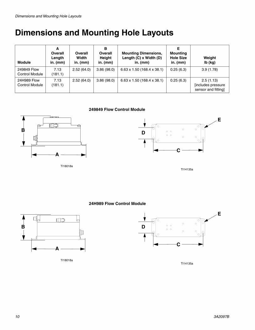
Dimensions and Mounting Hole Layouts
Module
AOverall Length
in. (mm)
Overall Width
in. (mm)
BOverall Height
in. (mm)
Mounting Dimensions, Length (C) x Width (D)
in. (mm)
EMounting Hole Sizein. (mm)
Weightlb (kg)
249849 Flow Control Module
7.13 (181.1)
2.52 (64.0) 3.86 (98.0) 6.63 x 1.50 (168.4 x 38.1) 0.25 (6.3) 3.9 (1.78)
24H989 Flow Control Module
7.13 (181.1)
2.52 (64.0) 3.86 (98.0) 6.63 x 1.50 (168.4 x 38.1) 0.25 (6.3) 2.5 (1.13)[includes pressure sensor and fitting]
TI18018a
249849 Flow Control Module
TI14135a
D
C
E
A
B
TI18018a
24H989 Flow Control Module
TI14135a
D
C
E
A
B
Technical Data
3A2097B 11
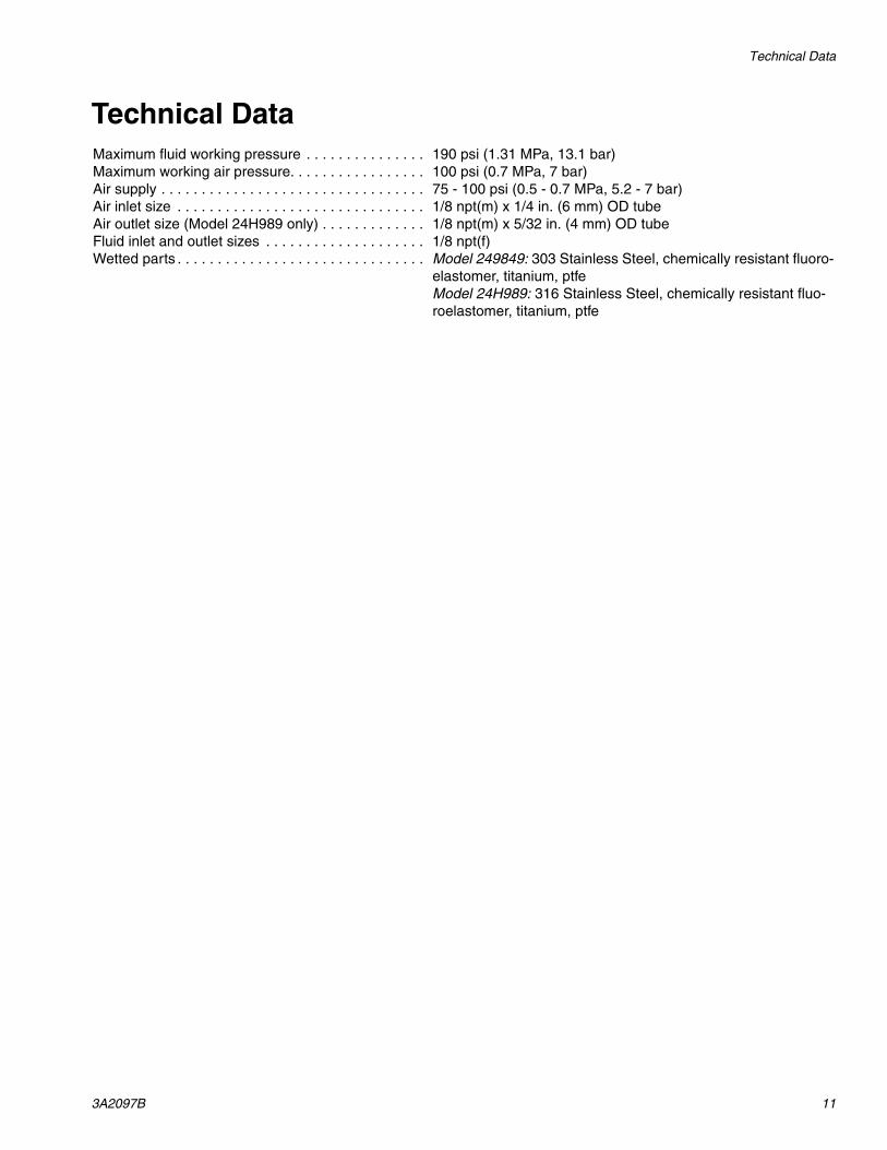
Technical DataMaximum fluid working pressure . . . . . . . . . . . . . . . 190 psi (1.31 MPa, 13.1 bar)Maximum working air pressure. . . . . . . . . . . . . . . . . 100 psi (0.7 MPa, 7 bar)Air supply . . . . . . . . . . . . . . . . . . . . . . . . . . . . . . . . . 75 - 100 psi (0.5 - 0.7 MPa, 5.2 - 7 bar)Air inlet size . . . . . . . . . . . . . . . . . . . . . . . . . . . . . . . 1/8 npt(m) x 1/4 in. (6 mm) OD tubeAir outlet size (Model 24H989 only) . . . . . . . . . . . . . 1/8 npt(m) x 5/32 in. (4 mm) OD tubeFluid inlet and outlet sizes . . . . . . . . . . . . . . . . . . . . 1/8 npt(f)Wetted parts . . . . . . . . . . . . . . . . . . . . . . . . . . . . . . . Model 249849: 303 Stainless Steel, chemically resistant fluoro-
elastomer, titanium, ptfeModel 24H989: 316 Stainless Steel, chemically resistant fluo-roelastomer, titanium, ptfe
All written and visual data contained in this document reflects the latest product information available at the time of publication. Graco reserves the right to make changes at any time without notice.
Original instructions. This manual contains English. MM 3A2097
Graco Headquarters: MinneapolisInternational Offices: Belgium, China, Japan, Korea
GRACO INC. AND SUBSIDIARIES • P.O. BOX 1441 • MINNEAPOLIS MN 55440-1441 • USA
Copyright 2011, Graco Inc. All Graco manufacturing locations are registered to ISO 9001.www.graco.com
Revised February 2013
Graco Standard WarrantyGraco warrants all equipment referenced in this document which is manufactured by Graco and bearing its name to be free from defects in material and workmanship on the date of sale to the original purchaser for use. With the exception of any special, extended, or limited warranty published by Graco, Graco will, for a period of twelve months from the date of sale, repair or replace any part of the equipment determined by Graco to be defective. This warranty applies only when the equipment is installed, operated and maintained in accordance with Graco’s written recommendations.
This warranty does not cover, and Graco shall not be liable for general wear and tear, or any malfunction, damage or wear caused by faulty installation, misapplication, abrasion, corrosion, inadequate or improper maintenance, negligence, accident, tampering, or substitution of non-Graco component parts. Nor shall Graco be liable for malfunction, damage or wear caused by the incompatibility of Graco equipment with structures, accessories, equipment or materials not supplied by Graco, or the improper design, manufacture, installation, operation or maintenance of structures, accessories, equipment or materials not supplied by Graco.
This warranty is conditioned upon the prepaid return of the equipment claimed to be defective to an authorized Graco distributor for verification of the claimed defect. If the claimed defect is verified, Graco will repair or replace free of charge any defective parts. The equipment will be returned to the original purchaser transportation prepaid. If inspection of the equipment does not disclose any defect in material or workmanship, repairs will be made at a reasonable charge, which charges may include the costs of parts, labor, and transportation.
THIS WARRANTY IS EXCLUSIVE, AND IS IN LIEU OF ANY OTHER WARRANTIES, EXPRESS OR IMPLIED, INCLUDING BUT NOT LIMITED TO WARRANTY OF MERCHANTABILITY OR WARRANTY OF FITNESS FOR A PARTICULAR PURPOSE.
Graco’s sole obligation and buyer’s sole remedy for any breach of warranty shall be as set forth above. The buyer agrees that no other remedy (including, but not limited to, incidental or consequential damages for lost profits, lost sales, injury to person or property, or any other incidental or consequential loss) shall be available. Any action for breach of warranty must be brought within two (2) years of the date of sale.
GRACO MAKES NO WARRANTY, AND DISCLAIMS ALL IMPLIED WARRANTIES OF MERCHANTABILITY AND FITNESS FOR A PARTICULAR PURPOSE, IN CONNECTION WITH ACCESSORIES, EQUIPMENT, MATERIALS OR COMPONENTS SOLD BUT NOT MANUFACTURED BY GRACO. These items sold, but not manufactured by Graco (such as electric motors, switches, hose, etc.), are subject to the warranty, if any, of their manufacturer. Graco will provide purchaser with reasonable assistance in making any claim for breach of these warranties.
In no event will Graco be liable for indirect, incidental, special or consequential damages resulting from Graco supplying equipment hereunder, or the furnishing, performance, or use of any products or other goods sold hereto, whether due to a breach of contract, breach of warranty, the negligence of Graco, or otherwise.
FOR GRACO CANADA CUSTOMERSThe Parties acknowledge that they have required that the present document, as well as all documents, notices and legal proceedings entered into, given or instituted pursuant hereto or relating directly or indirectly hereto, be drawn up in English. Les parties reconnaissent avoir convenu que la rédaction du présente document sera en Anglais, ainsi que tous documents, avis et procédures judiciaires exécutés, donnés ou intentés, à la suite de ou en rapport, directement ou indirectement, avec les procédures concernées.
Graco Information For the latest information about Graco products, visit www.graco.com. For patent information, see www.graco.com/patents.
TO PLACE AN ORDER, contact your Graco distributor or call to identify the nearest distributor.Phone: 612-623-6921 or Toll Free: 1-800-328-0211 Fax: 612-378-3505