Embed Size (px)
Citation preview
Journal of Sound and Vibration (2001) 245(5), 923-946doi:10.1006/jsvi.2001.3612, available online at http://www.idealibrary.com on IDE~L@-
.. @FLOW-INDUCED VIBRATIONS OF A LIGHT CIRCULAR
CYLINDER AT REYNOLDS NUMBERS 103 TO 104
S. MIlTALANOV. KUMAR
Department of Aerospace Engineering, Indian Institute of Technology, Kanpur, UP 208 016, India.E-mail: [email protected]
(Received 1 September 1999, and in final form 5 February 2001)
Stabilized space-time finite-element methods are employed to investigate vortex-inducedvibrations of a light circular cylinder placed in a uniform flow at Reynolds number in therange of 103-104. The governing equations for the fluid flow are the Navier-Stokesequations for incompressible flows. The cylinder is mounted on lightly damped, flexiblesupports and allowed to vibrate, both in the in-line and cross-flow directions under theaction of aerodynamic forces. Results are presented for various values of the structuralfrequency of the oscillator including those that are super-harmonics of the vortex-sheddingfrequency for a stationary cylinder. In certain cases the effect of the mass of the oscillator is
.also examined. The motion of the cylinder alters the fluid flow significantly. To investigatethe long-term dynamics of the non-linear oscillator, beyond the initial transient solution,long-time integration of the governing equations is carried out. For efficient utilization of theavailable computational resources the non-linear equation systems, resulting from thefinite-element discretization of the flow equations, are solved using the preconditionedgeneralized minimal residual (GMRES) technique. Flows at lower Reynolds numbers areassociated with organized wakes while disorganized wakes are observed at higher Reynoldsnumbers. In certain cases, competition is observed between various modes of vortexshedding. The fluid-structure interaction shows a significant dependence on the Reynoldsnumber in the range that has been investigated in this article. In certain cases lock-in while insome other cases soft-lock-in is observed. The trajectory of the cylinder shows veryinteresting patterns including the well-known Lissajou figure of 8. Several mechanisms of thenon-linear oscillator for self-limiting its vibration amplitude are observed.
(!:;) 2001 Academic Press
1. INTRODUCTION
Flow past an oscillating cylinder has received continued attention in the past few decades.In addition to being a building block in the understanding of bluff body flows it has a largenumber of applications in several engineering situations. Flow past an oscillating cylinder isassQciated with a variety of interesting phenomena. For example, a cylinder subjected tocross-flow vibrations exhibits the phenomenon of lock-in. The vortex-shedding frequencyrelated to the oscillating cylinder shifts to the frequency of cylinder vibrations [1]. However,this happens only if the oscillation amplitude is larger than a certain threshold value.Lock-in is observed for a fairly wide range of cylinder vibration frequencies centered aroundthe vortex shedding frequency for a stationary cylinder. Interestingly, the thresholdamplitude, beyond which lock-in takes place, increases with the increase in differencebetween the vibration frequency and the vortex shedding frequency of the stationarycylinder. Lock-in is also observed for cylinders that are mounted on flexible supports andare allowed to undergo vortex-induced oscillations [2]. Another interesting phenomenon
0022-460X/O1/350923 +24 $35.00/0 (!:;) 2001 Academic Press
924 S. MITrAL AND V. KUMAR
associated with vortex-induced oscillations is hysteresis. The oscillation amplitude, fora certain range of Reynolds number and close to the outer limits of the frequencies forlock-in, depends on whether the flow speed is decreased or increased during the experiment[3]. Several explanations have been offered by researchers in the past. While someresearchers attribute it to the non-linear springs in the mountings, others suspect it to bea consequence of variable structural damping. More details of these phenomena can befound in the work by Toebes [4], Griffin [5], Tanida et al. [6], Griffin and Ramberg [7],King [8], Durgin et al. [9], Lecointe et al. [10], Chen [11], Williamson [12], Olinger andSreenivasan [13], Ongoren and Rockwell [14, 15], Blevins [16], Mittal and Tezduyar [17],Mittal et al. [18], Chang and Sa [19], and Mittal and Kumar [20]. Many of these studiesfocus on the wake of the cylinder that is subjected to forced oscillations at variousfrequencies, including those that are sub- and super-harmonics of the natural -;
vortex-shedding frequency for a stationary cylinder. Some of the studies deal withvortex-induced oscillations of a cylinder mounted on flexible supports. Most of the earlierresearch efforts are based on laboratory experiments while some of the more recent ones .[10, 17-20] utilize computational methods.
Mittal and Tezduyar [17] reported their results for a computational study of flows pastan oscillating cylinder using the finite-element method. They observed that a cylindersubjected to in-line oscillations at a certain freq~ency results in a symmetric mode of vortexshedding. For a cylinder restricted to cross-flow vortex-induced vibrations, they were ableto observe the phenomena of lock-in and hysteresis. The Reynolds numbers for theircomputations are in the range of 290-300. They also attempted to explain the cause ofhysteresis through numerical experiments and concluded that it is a consequence of lock-in.Lock-in occurs only if the vibration amplitude of the cylinder is greater than a certainthreshold value [1]. For a certain range of Reynolds number, if the initial conditioncorresponds to a cylinder vibrating with large amplitude that is beyond the threshold valuefor lock-in, the vortex-shedding frequency locks on to the structural frequency and onerealizes a high-amplitude solution. On the other hand, if one begins with a solution thatcorresponds to low-amplitude oscillations, that is below the threshold required for lock-in,a low-amplitude solution is realized. Later, in another study, Mittal and Kumar [20]applied their methodology to investigate the fluid-induced vibrations of a lighter cylinder,mounted on lightly damped spring supports, and free to move in cross-flow and in-linedirections. The mass of the oscillator in this study is l/l00th of the one in the earlierinvestigation by Mittal and Tezduyar [17]. The lighter mass is used to encourage in-lineoscillations. The Reynolds number for their study is 325 and computations are carried out .for various values of the structural frequency including the sub- and super-harmonics of thenatural vortex-shedding frequency for a stationary cylinder. The computations lead tovarious interesting observations. Lock-in is observed for a range of values of the structural j
frequency, but, in a slightly modified form. Over a certain range of structural frequency (Fs),when it is slightly larger than the natural vortex-shedding frequency (Fa), the vortex-shedding frequency of the oscillating cylinder does not exactly match the structuralfrequency; there is a slight detuning that increases as Fs moves away from Fa. Mittal andKumar referred to it as soft lock-in. They also observed that this phenomenon of soft lock-inis associated with light cylinders only. As the mass of the cylinder is increased, thevortex-shedding frequency of the oscillating cylinder shifts towards the structural frequencyof the oscillator. They proposed that soft lock-in is a mechanism of the non-linear oscillatorto self-limit its vibration amplitude. The flow field changes significantly to restrict theamplitude of cylinder vibration. The other mechanisms of the oscillator to restrict itsvibration amplitude, via a change in the flow field, are a reduction in the magnitude ofaerodynamic forces and the appearance of additional frequencies in their power spectra.
FLOW-INDUCED VIBRATIONS 925
In this article, the investigation carried out by Mittal and Kumar [20] is being extendedto flows at higher Reynolds numbers. The Reynolds numbers, based on the diameter of thecylinder, free-stream speed and the fluid viscosity, lie between 103 and 104. Unlike the flowsfor low Reynolds numbers the wake behind the cylinder, for high Reynolds numbers, isquite disorganized. In certain cases a competition is observed between various modes ofvortex shedding. In this context, the dependence of the solution on the Reynolds number isobserved to be quite significant. For certain cases, the effect of the mass of the oscillator isalso studied.
The outline of the rest of the article is as follows. A brief review of the governing equationsfor incompressible fluid flow and for the motion of a rigid body under the influence ofunsteady fluid forces is given in section 2. Section 3 describes the stabilized finite-elementformulation of the governing equations. It is based on the space-time finite-element methodin which the finite-element interpolation functions depend both on space and time. This waythe deformation of the spatial domain is taken into account automatically. This method,known as the DSD/SST (deforming spatial domain/stabilized space-time) technique, wasintroduced by Tezduyar et at. [21, 22]. To stabilize the computations against spuriousnumerical oscillations and to enable the use of equal-order-interpolation velocity-pressureelements the Galerkinjleast-squares (GLS) stabilization technique is employed. Section3 describes the finite element formulation incorporating these stabilizing terms. Toaccommodate the motion of the cylinder, and therefore the mesh, special mesh-movingschemes, as described by Mittal and Tezduyar [17], are used. Such special purposemesh-moving strategies are very quick and allow one to completely do away with theremeshing. The non-linear equation systems resulting from the finite-element discretizationof the flow equations are solved using the generalized minimal residual (GMRES) technique[23] in conjunction with diagonal preconditioners. Results and discussions are presented insection 4 and we end with some concluding remarks in section 5.
2. THE GOVERNING EQUATIONS
Let Dt c JR"" and (0, T) be the spatial and temporal domains, respectively, where nod isthe number of space dimensions, and let r, denote the boundary of Dt. The spatial andtemporal co-ordinates are denoted by x and t. The Navier-Stokes equations governingincompressible fluid flow are
p(~ + u.Vu - f) - V.a = 0 on Dt for (0, T), (1)
V.u = 0 on Dt for (0, T). (2)
Here p, u, f and a are the density, velocity, body force .and the stress tensor respectively. Thestress tensor is written as the sum of its isotropic and deviatoric parts:
a = - pI + T, T = 2,uE(U), E(U) = !((Vu) + (VU)T), (3)
where p and ,u are the pressure and viscosity. Both the Dirichlet and Neumann-typeboundary conditions are accounted for, represented as
U = g on (r,)g, R.a = h on (r,)h, (4)
926 S. MITTAL AND V. KUMAR
where (r,)g and (r,)h are complementary subsets of the boundary Fr. The initial condition onthe velocity is specified on Dt at t = 0:
u(x,O) = Uo on Do, (5)
where Uo is divergence free.A solid body immersed in the fluid experiences unsteady forces and in certain cases may
exhibit rigid body motion. The motion of the body, in the two directions along the cart,esianaxes, is governed by the following equations:
X + 2nF.'X + (nF.)2X = ~ for (0, T), (6)
.. . 2 CL(7)Y + 2nF.'Y + (nF.) Y = M for (0, T).
Here, F. is the reduced natural frequency of the oscillator, , is the structural dampingcoefficient, M is the non-dimensional mass of the body, while CL and CD are theinstantaneous lift and drag coefficients for the body respectively. The free-stream flow isassumed to be along the x-axis, X, X and X denote the normalized in-line acceleration,velocity and displacement of the body, respectively, while Y, Yand Y represent the samequantities associated with the cross-flow motion. In the present study, in which the rigidbody is a circular cylinder, the displacement and velocity are normalized by the radius ofthe cylinder and the free-stream speed respectively. The reduced natural frequency of thesystem, F. is defined as 2!.a/U"", where!. is the actual frequency of the oscillator, a is theradius of the cylinder and U"" is the free-stream speed of the flow. The non-dimensionalmass of the cylinder is defined as M = 2mb/p""a2, where mb is the actual mass of theoscillator and P"" is the density of the fluid. The initial conditions for the displacement andvelocity of the cylinder are specified at t = 0:
X(O) = XO, X(O) = X 0, (8)
Y(O) = Yo, Y(O) = Yo. (9)
The equations governing the fluid flow are solved in conjunction with those for the motionof the cylinder. The force acting on the body is calculated by integrating the flow variables -.
on the body surface. The resulting drag and lift coefficients are used to compute thedisplacement and velocity of the body which are then used to update the location of thebody and the no-slip boundary condition for the velocity field on the body surface. ;
3. FINITE-ELEMENT FORMULATIONS
To accommodate the motion of the cylinder and the deformation of the mesh thestabilized finite-element formulation is employed. In order to construct the finite-elementfunction spaces for the space-time method, we partition the time interval (0, T) intosubintervals In = (tn, tn+ J, where tn and tn+ 1 belong to an ordered series of time levels0 = to < t1 < ... < tN = T. Let Dn = Dt. and rn = r,.. We define the space-time slab Qn asthe domain enclosed by the surfaces, Dn, Dn + 1, and Pn, where P n is the surface described bythe boundary r, as t traverses In. As is the case with r" surface Pn is decomposed into (Pn)gand (P n)h with respect to the type of boundary condition (Dirichlet or Neumann) beingimposed. For each space-time slab we define the corresponding finite-element function
FLOW-INDUCED VIBRATIONS 927
spaces (f/':)n, ('f;;h)n, (.:!'ph)n, and ("I/':)n. Over the element domain, this space is formed byusing first order polynomials in space and time. Globally, the interpolation functions arecontinuous in space but discontinuous in time.
The stabilized space-time formulation for deforming domains is then written as follows:given (uh)n-' find Uh E (f/':)n and ph E (.:!'ph)n such that 'v'wh E ('f;;h)n, qh E ("I/'ph)n
I Wh.p (~ + Uh.VUh - r)dQ + I E(wh):a(ph, uh)dQ + I qhV.uhdQQo Qo Qo
n" 1 1 [(OWh ) ]+ L -t P - + Uh.VWh - V.a(qh, Wh)
e=l Q:P ot
. [ P (~ + uh. VUh - r) - V. a(ph, uh) ] dQ
+ ~ I bv.whpv.uhdQ+ I (Wh):.p((uh): -(Uh);)dD= I wh.hhdP. (10)e= 1 Q: Do (Po)'
This process is applied sequentially to all the space-time slabs Ql, Q2, ..., QN-l. In thevariational formulation given by equation (10), the following notation is used:
(uh)~ = lim u(tn :I: e), (11).-+0
I (...)dQ = f I (...)dDdt, (12)Q. I. D.
f (...)dP = f f (...)drdt. (13)P. I. r.
The computations start with
(Uh)O = Do, (14)
where 00 is divergence free.In the variational formulation given by equation (10), the first three terms and the
right-hand side constitute the Galerkin formulation of the problem. The series of element-level integrals involving the coefficients t and b are the least-squares terms that are added tothe basic Galerkin formulation to ensure the stability of the computations. This type ofstabilization is referred to as the Galerkinj1east-squares (GLS) procedure and isa generalization of the streamline-upwindjPetrov-Galerkin (SUPG) and pressure-stabilizingjPetrov-Galerkin) (PSPG) method [24]. In the current formulation t and baregiven as
-((2110h 11)2 (4V)2)-l/2 t - --;:;- + h"2' (15)
hb = :2llohllz, (16)
928 S. MITTAL AND V. KUMAR
where
z = { (~), Reu ~ 3,1, Reu > 3
and Reu is the cell Reynolds number. Both stabilization terms are weighted residuals, andtherefore maintain the consistency of the formulation. The sixth term in equation (10)enforces weak continuity of the velocity field across the space-time slabs.
The equations of motion for the oscillator given by equations {6)-(9) are also cast in thespace-time formulation in the same manner as described in the work by Tezduyar et at. [22]and Mittal [25].
4. RESULTS AND DISCUSSIONS
A cylinder of non-dimensional mass M = 4.7273 and the structural damping coefficient, = 3,3 X 10-04 is placed in a uniform flow. The outer boundary of the computationaldomain is rectangle whose upstream and downstream edges are located at 8 and 22.5cylinder diameters from the center of the cylinder respectively. The upper and lower edgesare placed at eight diameters from the center of the cylinder. At the cylinder surface, theno-slip boundary condition is applied for the velocity. Free-stream values are assigned forthe velocity at the upstream boundary while at the downstream boundary, the viscous stressvector is assumed to be zero. On the upper and lower bQundaries, the component of velocitynormal to and the component of stress vector along these boundaries is prescribed zerovalue. Computations are carried out for Reynolds numbers 1000, 1500 and 10000 forvarious values of the non-dimensional structural frequency (Fs) of the spring-mass system.The effect of mass (M) of the oscillator is also investigated for some cases. The Reynoldsnumber is based on the diameter of the cylinder, free-stream velocity and the viscosity of thefluid. Results for a similar set-up at Reynolds number 325 have been reported in an earlierarticle [20]. Mittal and Tezduyar [17] reported results for a heavier cylinder whose motionis restricted to the cross-flow direction for flows with Reynolds numbers in the range of290-360. The mass of the cylinder in the present study and the one reported in reference[20] is l/l00th of the one considered by Mittal and Tezduyar [17]. The lower mass of theoscillator is to encourage in-line oscillations. The damping coefficient has the same value in .all the three studies.
All the computations reported in this article are carried out on the Digital workstationsat liT Kanpur in 64 bit precision. Equal-in-order basis functions for velocity and pressure, ,that are bilinear in space and linear in time, are used and 2 x 2 x 2 Gaussian quadrature isemployed for numerical integration. The non-linear equation systems resulting from thefinite-element discretization of the flow equations are solved using the GMRES technique[23] in conjunction with diagonal preconditioners.
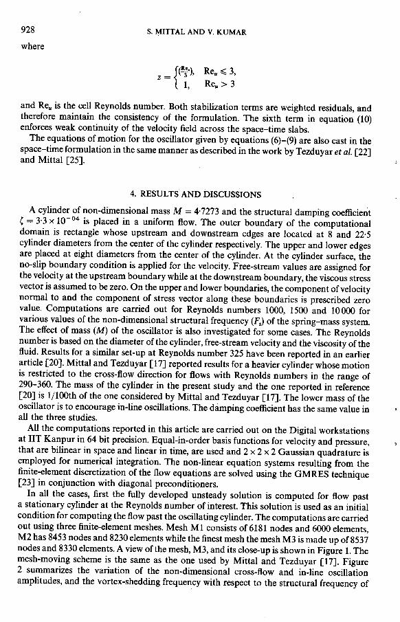
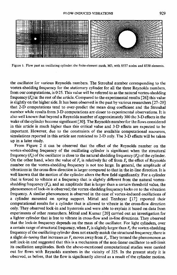
In all the cases, first the fully developed unsteady solution is computed for flow pasta stationary cylinder at the Reynolds number of interest. This solution is used as an initialcondition for computing the flow past the oscillating cylinder. The computations are carriedout using three finite-element meshes. Mesh Ml consists of 6181 nodes and 6000 elements,M2 has 8453 nodes and 8230 elements while the finest mesh the mesh M3 is made up of 8537nodes and 8330 elements. A view of the mesh, M3, and its close-up is shown in Figure 1. Themesh-moving scheme is the same as the one used by Mittal and Tezduyar [17]. Figure2 summarizes the variation of the non-dimensional cross-flow and in-line oscillationamplitudes, and the vortex-shedding frequency with respect to the structural frequency of
FLOW-INDUCED VIBRATIONS 929
Figure 1. Flow past an oscillating cylinder: the finite-element mesh, M3, with 8537 nodes and 8330 elements.
the oscillator for various Reynolds numbers. The Strouhal number corresponding to thevortex-shedding frequency for the stationary cylinder for all the three Reynolds numbers,from our computations, is 0.25. This value will be referred to as the natural vortex-sheddingfrequency (Fo) in the rest of the article. Compared to the experimental results [26] this valueis slightly on the higher side. It has been observed in the past by various researchers [27-29]that 2-D computations tend to over-predict the mean drag coefficient and the Strouhalnumber while results from 3-D computations are closer to experimental observations. It isalso well known that beyond a Reynolds number of approximately 300 the 3-D effects in thewake of the cylinder become significant [30]. The Reynolds number for the flows consideredin this article is much higher than this critical value and 3-D effects are expected to beimportant. However, due to the constraints of the available computational resources,simulations reported in this article are restricted to 2-D only. The 3-D effects will be takenup in a later study.
From Figure 2 it can be observed that the effect of the Reynolds number on thevortex-shedding frequency of the oscillating cylinder is significant when the structuralfrequency (1':.) of the oscillator is close to the natural shedding frequency (Fo) of the cylinder.On the other hand, when the value of Fs is relatively far off from Fo the effect of Reynoldsnumber on the vortex-shedding frequency is not too large. In general, the amplitude ofvibrations in the cross-flow direction is larger compared to that in the in-line direction. It iswell known that the motion of the cylinder alters the flow field significantly. For a cylinderthat is forced to vibrate at a frequency that is slightly different from the natural vortex-shedding frequency (F 0)' and an amplitude that is larger than a certain threshold value, thephenomenon of lock-in is observed; the vortex-shedding frequency locks on to the vibrationfrequency. A similar phenomenon is observed in the case of vortex-induced oscillations ofa cylinder mounted on spring support. Mittal and Tezduyar [17] reported theircomputational results for a cylinder that is allowed to vibrate in the cross-flow directiononly. They observed lock-in and hysteresis and were able to explain it based on data fromexperiments of other researchers. Mittal and Kumar [20] carried out an investigation fora lighter cylinder that is free to vibrate in cross-flow and in-line directions. They observedthat the lock-in frequency depends on the mass of the oscillator. For light cylinders, overa certain range of structural frequency, when Fs is slightly larger than Fo the vortex-sheddingfrequency of the oscillating cylinder does not exactly match the structural frequency; there isa slight de-tuning that increases as Fsmoves away from Fo. They termed the phenomenon assoft lock-in and suggested that this is a mechanism of the non-linear oscillator to self-limitits oscillation amplitudes. Both the above-mentioned computational studies were carriedout for flows with Reynolds numbers in the vicinity of 325. In the present study it isobserved, as before, that the flow is significantly altered as a result of the cylinder motion.
930 S. MITTAL AND V. KUMAR
0,35
0,30 'II
0.25
~ 0.20 . ~
~ ::: "'...
!::!. 0.15 ::::' """...
0.10 :::::.: "i!J"""""""'i3~""""".'."".s 0,05 ..,~,.~ v .,
!!I""
0,000.1 0.2 0,3 0,4 0,5 0.6 0,7 0.8 0,9
Fs
1,2
;~.".I:].0,9 ! V""""...
! "~;. \~ .: .',~ 0,6 In ~~
N ~"-' \~
0,3 '~
~""".'."".S~'--"""--"-"';""-""""""
0,00.1 0,2 0-3 0,4 0,5 0,6 0,7 0,8 0-9
Fs
0,35
0,30';;.8§ J:;J ...I: : --
-;; 0,25 :,: """ .1:]~ . - ..,~ ..8... V ,P -, .':3 8"', ,.
~ .', ~ II. 0.20 "-B G--""""""8~'-""""--"".
V.0,15
0.1 0,2 0,3 0,4 0,5 0,6 0,7 0,8 0,9
Fs
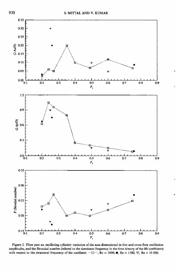
Figure 2. Flow past an oscillating cylinder: variation of the non-dimensional in-line and cross-flow oscillationamplitudes, and the Strouhal number (related to the dominant frequency in the time history of the lift coefficient)with respect to the structural frequency of the oscillator. .. '[:J' -., Re = 1000; 8, Re = 1500; ~, Re = 10 000.
FLOW-INDUCED VIBRATIONS 931
The "de-tuning" that was observed for the Reynolds number 325 flow is seen in a moreexaggerated form in the present case.
4.1. Re = 1000
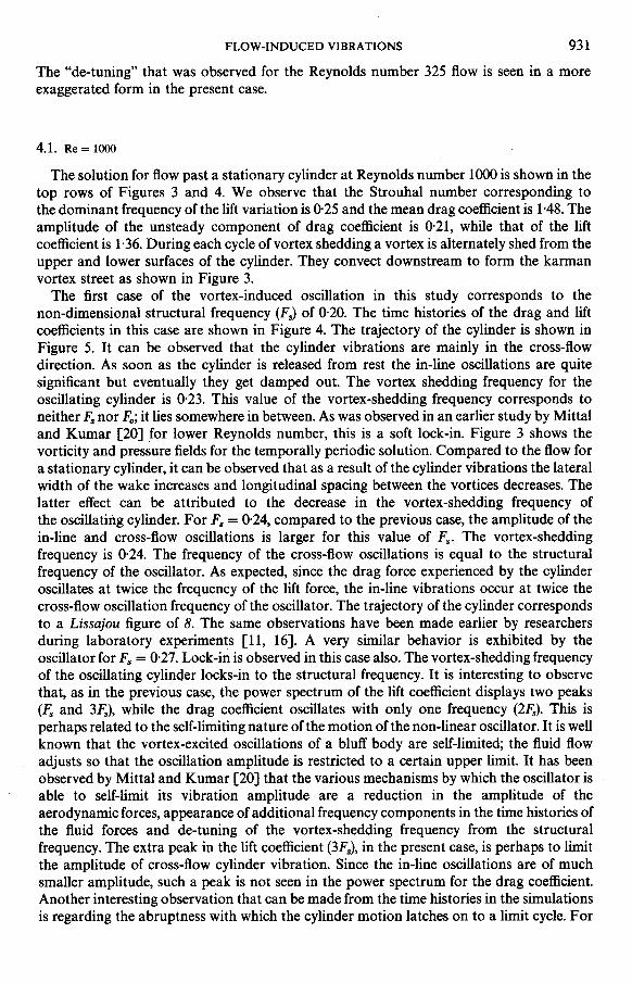
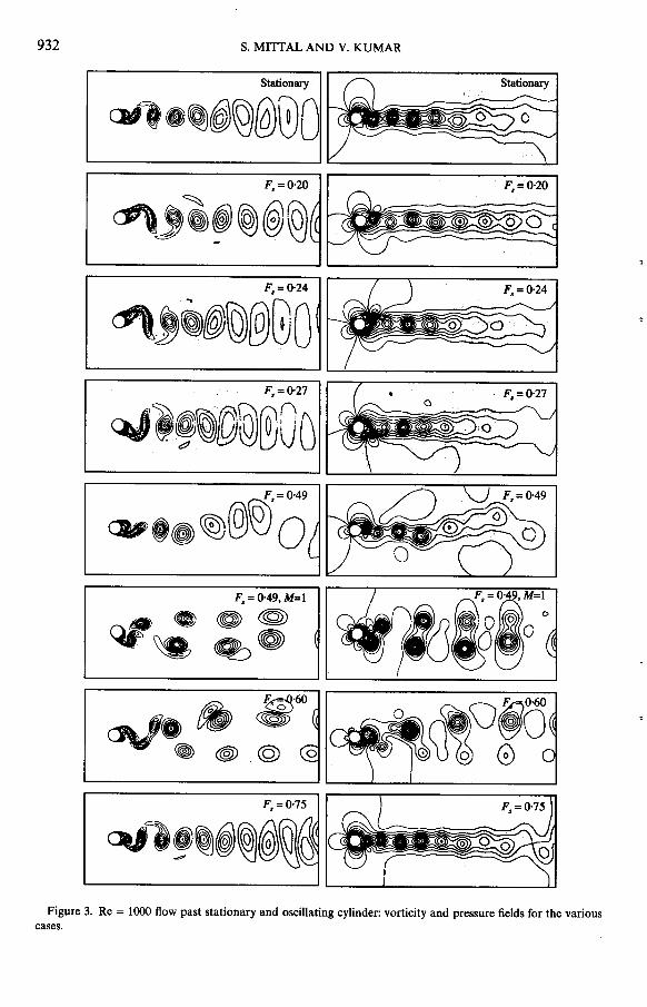
The solution for flow past a stationary cylinder at Reynolds number 1000 is shown in thetop rows of Figures 3 and 4. We observe that the Strouhal number corresponding tothe dominant frequency of the lift variation is 0.25 and the mean drag coefficient is 1.48. Theamplitude of the unsteady component of drag coefficient is 0,21, while that of the liftcoefficient is 1.36. During each cycle of vortex shedding a vortex is alternately shed from theupper and lower surfaces of the cylinder. They convect downstream to form the karmanvortex street as shown in Figure 3.
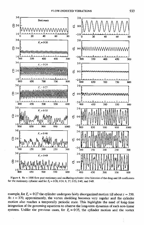
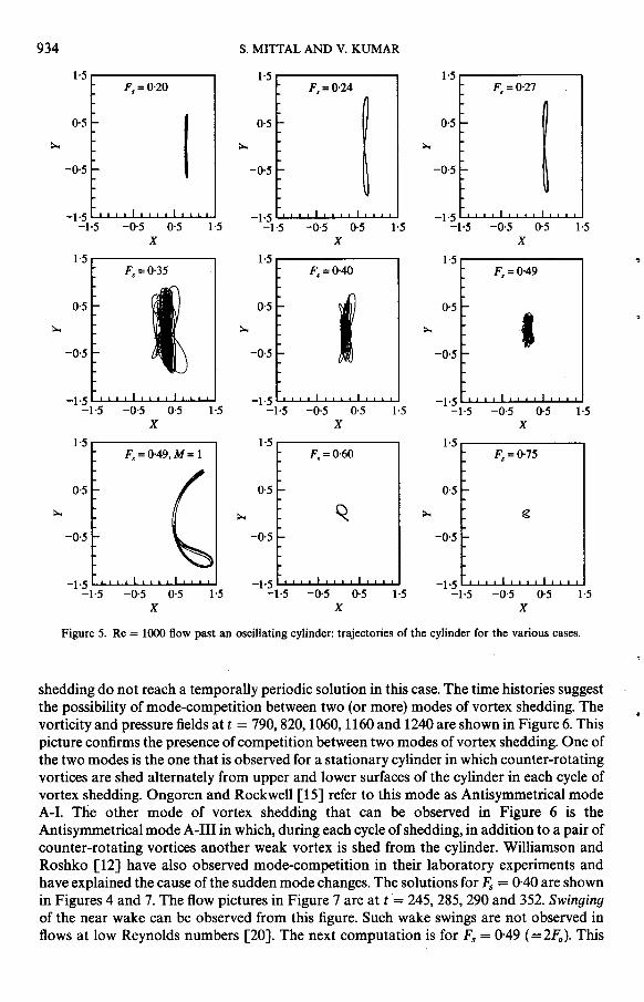
The first case of the vortex-induced oscillation in this study corresponds to thenon-dimensional structural frequency (Fs) of 0.20. The time histories of the drag and liftcoefficients in this case are shown in Figure 4. The trajectory of the cylinder is shown inFigure 5. It can be observed that the cylinder vibrations are mainly in the cross-flowdirection. As soon as the cylinder is released from rest the in-line oscillations are quitesignificant but eventually they get damped out. The vortex shedding frequency for theoscillating cylinder is 0.23. This value of the vortex-shedding frequency corresponds toneither Fs nor Fo; it lies somewhere in between. As was observed in an earlier study by Mittaland Kumar [20] for lower Reynolds number, this is a soft lock-in. Figure 3 shows thevorticity and pressure fields for the temporally periodic solution. Compared to the flow fora stationary cylinder, it can be observed that as a result of the cylinder vibrations the lateralwidth of the wake increases and longitudinal spacing between the vortices decreases. Thelatter effect can be attributed to the decrease in the vortex-shedding frequency ofthe oscillating cylinder. For Fs = 0.24, compared to the previous case, the amplitude of thein-line and cross-flow oscillations is larger for this value of Fs. The vortex-sheddingfrequency is 0.24. The frequency of the cross-flow oscillations is equal to the structuralfrequency of the oscillator. As expected, since the drag force experienced by the cylinderoscillates at twice the frequency of the lift force, the in-line vibrations occur at twice thecross-flow oscillation frequency of the oscillator. The trajectory of the cylinder correspondsto a Lissajou figure of 8. The same observations have been made earlier by researchersduring laboratory experiments [11, 16]. A very similar behavior is exhibited by theoscillator for Fs = 0.27. Lock-in is observed in this case also. The vortex-shedding frequencyof the oscillating cylinqer locks-in to the structural frequency. It is interesting to observethat, as in the previous case, the power spectrum of the lift coefficient displays two peaks(£, and 3£,), while the drag coefficient oscillates with only one frequency (2£,). This isperhaps related to the self-limiting nature of the motion of the non-linear oscillator. It is wellknown that the vortex-excited oscillations of a bluff body are self-limited; the fluid flowadjusts so that the oscillation amplitude is restricted to a certain upper limit. It has beenobserved by Mittal and Kumar [20] that the various mechanisms by which the oscillator isable to self-limit its vibration amplitude are a reduction in the amplitude of theaerodynamic forces, appearance of additional frequency components in the time histories ofthe fluid forces and de-tuning of the vortex-shedding frequency from the structuralfrequency. The extra peak in the lift coefficient (3Fs), in the present case, is perhaps to limitthe amplitude of cross-flow cylinder vibration. Since the in-line oscillations are of muchsmaller amplitude, such a peak is not seen in the power spectrum for the drag coefficient.Another interesting observation that can be made from the time histories in the simulationsis regarding the abruptness with which the cylinder motion latches on to a limit cycle. For
932 S. MITTAL AND V. KUMAR
Stationary
cW1.~(@)~@00
F,=0'20
~~~~@@F = 0'24,
~J~(@)~@GO .
F. = 0.27
~i!JOO@00DF = 0,49
~,~~@~'oF,=0'49,M=1
..G~~~ ~~
(0. :g;'60 .c:I\J1~(@)@
F,=O.
~~ :!J~~~(@~lG
Figure 3. Re = 1000 flow past stationary and oscillating cylinder: vorticity and pressure fields for the variouscases.
FLOW-INDUCED VIBRATIONS 933
3-0~;~~~~~~~d 2-0Mill~~~~~ Stationary82-0 d 0-01-0 -2-00 20 40 60 80 0 20 40 60 803-0~ ~~;~;~~~ 2-0
r ~~~~~~~ F = 0-20 8 2-0 s d 0-01-0 -2-0300 350 400 450 500 300 350 400 450 5003-0~ ~~~~~~~~~~' = 0.24 2-0
E ===:==~ 8 2.0 d 0.01.0 -2-0600 650 700 750 800 600 650 700 750 8003.0~ i~~~~~~~ 2 -0
E :::::::j F = 0.27 8 2-0" d 0.01.0 -2.0400 450 500 550 600 400 450 500 550 6003.0i ~~~~~~~ 2.0
~ lW~~I~~~~ F = 0.35 82.0 s d 0-01.0 -2.0 I800 850 900 950 1000 800 850 900 950 10003-0~ ~~1~;tJ 2-0 F = 0-40
8 ::' d -:::100 150 200 250 300 100 150 200 250 3003-0~ ~;~~;~~ 2-0
~ ~~~~~~ffim F = 0-49 82-0 s d 0.01-0 -2-0400 450 500 550 600 400 450 500 550 600Figure 4- Re = 1000 flow past stationary and oscillating cylinder: time histories of the drag and lift coefficientsfor the stationary cylinder and for Fs = 0-20, 0-24, 0,27,0-35,0-40, and 0.49.example, for F. = 0.27 the cylinder undergoes fairly disorganized motion till about t = 350-
At t = 370, approximately, the vortex shedding becomes very regular and the cylinder
motion also reaches a temporally periodic state. This highlights the need of long-time
integration of the governing equations to observe the long-term dynamics of such non-linear
systems. Unlike the previous cases, for F. = 0'35, the cylinder motion and the vortex
934 S. MITrAL AND V, KUMAR
1-5 1,5 1.5F =0-20 F =0,24 F =0-27s s s
0-5 I 0-5 0-5
;... ;... ;...
-0-5 -0-5 -0-5
-1-5 -1-5 -1-5-1-5 -0,5 0-5 1,5 -1,5 -0-5 0-5 1,5 -1-5 -0-5 0-5 1,5
X X X
1.5 1-5 1,5 .,F =0.35 F =0.40 F =0-49s s s
0-5 , 0-5 f 0-5 ;... ;... ;... I .-0-5 -0,5 -0-5
-1-5 -1-5 -1-5-1-5 -0-5 0-5 1-5 -1-5 -0,5 0-5 1,5 -1-5 -0-5 0,5 1-5
X X X
1.5 1-5 1-5F = 0.60 F = 0-75s s
0-5 0.5 0,5
;... ;... Q. ;... g
-0-5 -0-5 -0-5
-1-5 -1-5 -1-5-1-5 -0-5 0,5 1,5 -1,5 -0-5 0-5 1,5 -1-5 -0-5 0-5 1-5
X X X
Figure 5. Re = 1000 flow past an oscillating cylinder: trajectories of the cylinder for the various cases,
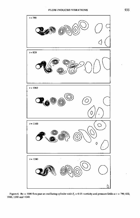
.shedding do not reach a temporally periodic solution in this case- The time histories suggestthe possibility of mode-competition between two (or more) modes of vortex shedding- The.vorticity and pressure fields at t = 790,820, 1060, 1160 and 1240 are shown in Figure 6- Thispicture confirms the presence of competition between two modes of vortex shedding- One ofthe two modes is the one that is observed for a stationary cylinder in which counter-rotatingvortices are shed alternately from upper and lower surfaces of the cylinder in each cycle ofvortex shedding- Ongoren and Rockwell [15] refer to this mode as Antisymmetrical modeA-I- The other mode of vortex shedding that can be observed in Figure 6 is theAntisymmetrical mode A-III in which, during each cycle of shedding, in addition to a pair ofcounter-rotating vortices another weak vortex is shed from the cylinder- Williamson andRoshko [12] have also observed mode-competition in their laboratory experiments andhave explained the cause of the sudden mode changes- The solutions for Fs = 0-40 are shown
in Figures 4 and 7. The flow pictures in Figure 7 are at t= 245, 285, 290 and 352. Swingingof the near wake can be observed from this figure. Such wake swings are not observed inflows at low Reynolds numbers [20]. The next computation is for Fs = 0-49 (=2Fo)- This
FLOW-INDUCED VIBRATIONS 935
t = 790
~~ tJJ ~ (§) \9) 0cJ
t= 820
,...8;:' (~~~~~~fl O0(J'~o ~"U'. i
t = 1060
~~.llI> @
t= 1160 ~
~,,:- @\J~°0
t = 1240
~ ~~(@)~ 0D
Figure 6. Re = 1000 flow past an oscillating cylinder with F. = 0,35: vorticity and pressure fields at t = 790,820,1060, 1160 and 1240.
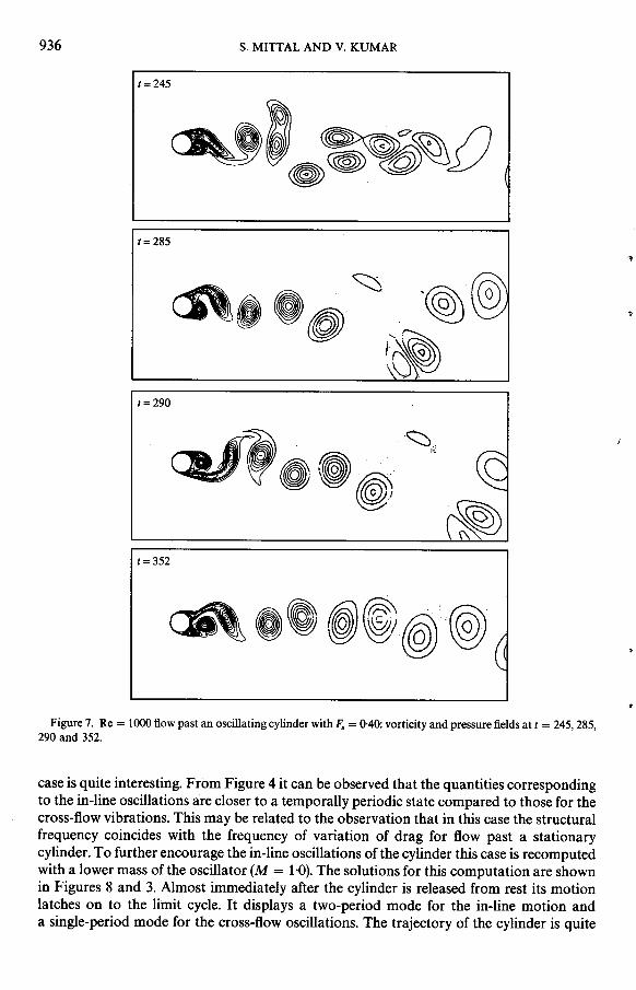
936 S. MITTAL AND V. KUMAR
t = 245
(::~III-!~~~I~~ - ~~e~;~~~~4 ~ /l~~ ~ IV
t=285~
cR, .(§j)~,: '~ C?) .
r~~t = 290
~,o.~.~';; J
~! ~t = 352
~ .' ~~@,@ ;
.Figure 7. Re = lOOO flow past an oscillating cylinder with F:; = 0,40: vorticity and pressure fields at t = 245, 285,
290 and 352.
case is quite interesting. From Figure 4 it can be observed that the quantities correspondingto the in-line oscillations are closer to a temporally periodic state compared to those for thecross-flow vibrations. This may be related to the observation that in this case the structuralfrequency coincides with the frequency of variation of drag for flow past a stationarycylinder. To further encourage the in-line oscillations of the cylinder this case is recomputedwith a lower mass of the oscillator (M = 1'0). The solutions for this computation are shownin Figures 8 and 3. Almost immediately after the cylinder is released from rest its motionlatches on to the limit cycle. It displays a two-period mode for the in-line motion anda single-period mode for the cross-flow oscillations. The trajectory of the cylinder is quite
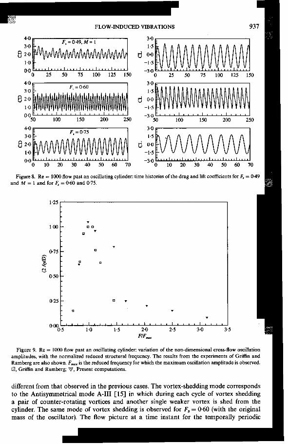
-FLOW-INDUCED VIBRAllONS 937
4-0~ ~~~~~~ 3-0 M~~~~~MM F,=0-49,M= I
3-0 1-5
e 2.0 d 0-01-0 -1-5
0.0 -3-00 25 50 75 100 125 150 0 25 50 75 100 125 150
4-0~ i~:ii~~~~ 3.0
~ ~~~~~~~~ F = 0.60 3.0' 1-5 8 2.0 d 0.0
1.0 -1.5
0.0 -3.050 100 150 200 250 50 100 150 200 250
4.0 ~ ~~~~)~~ 3.0~ ~~~~i~~~] F = 0-75 3-0' 1.5 e 2.0 d 0.0 '
1-0 -1-5
0.0 -3-0
0 10 20 30 40 50 60 70 0 10 20 30 40 50 60 70
Figure 8. Re = 1000 flow past an oscillating cylinder: time histories of the drag and lift coefficients for F, = 0.49
and M = 1 and for F:, = 0.60 and 0.75.
:1!!
1.25
.
1.00 D D.
D
.
0-75 D
S'
~ D D
-< .
~
0.50
0.25 B .
.
B .
.
0.000-5 1.0 1.5 2-0 2-5 3-0 3-5
FIF-
Figure 9. Re = 1000 flow past an oscillating cylinder: variation of the non-dimensional cross-flow oscillation~ amplitudes, with the normalized reduced structural frequency- The results from the experiments of Griffin and
Ramberg are also shown. F...x is the reduced frequency for which the maximum oscillation amplitude is observed.
~ G, Griffin and Ramberg; 'fl, Present computations-
~~
[[1 different from that observed in the previous cases. The vortex-shedding mode correspondsto the Antisymmetrical mode A-III [15] in which during each cycle of vortex sheddinga pair of counter-rotating vortices and another single weaker vortex is shed from thecylinder. The same mode of vortex shedding is observed for F. = 0,60 (with the original
k:aI' of the oscillator). The flow picture at a time instant for the temporally periodic
938 S. MITrAL AND V. KUMAR
solution is shown in Figure 3. In the previous case (M = 1, F. = 0.49), the additional singlevortex, that is shed in addition to the vortex pair of each cycle, is released from the uppersurface while in the present case (M = 4'7273, F. = 0.60), it is released from the lower surfaceof the cylinder. The power spectrum of the lift coefficient, in the current case, shows twopeaks, one at the vortex-shedding frequency (0'22) and the other at twice the value (0.44). Inthe other cases of periodic vortex shedding for an oscillating cylinder when theAntisymmetrical mode A-I is observed, the second peak in the power spectrum of the liftcoefficient corresponds to thrice the vortex-shedding frequency. The cause of theappearance of the second peak is quite different in the two cases. For F. = 0.60 it is causedby the additional single vortex shed during each vortex-shedding cycle while the peak in thelatter case is due to the local modification of the flow to self-limit the cross-flow vibration;amplitude. The last case that has been studied for Re = 1000 is for F. = 0,75 (=3Fo). Thesolutions corresponding to this case are shown in Figures 3, 5 and 8. The cylinder undergoessmall amplitude vibrations and the flow field is quite similar to that for a stationary ~cylinder. The power spectrum for the lift coefficient shows only one dominant frequency. .
This is consistent with our earlier observation that for the Antisymmetrical mode A-I ofvortex shedding the second peak in the power spectrum for the lift coefficient appears onlywhen the cylinder vibrates with a large amplitude in the cross-flow direction.
In Figure 9 results from the present computations are compared to the results of Griffinand Ramberg [31] for their experiments with a cylinder allowed to vibrate in water. It canbe noticed that the two sets of results are in fairly good agreement. This observationincreases our confidence in the present set of computations.
4.2. Re = 1500
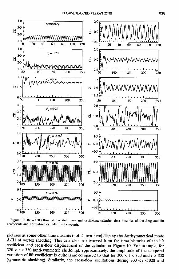
Based on the observation that the flows at Re = 1500 and 1000 for a stationary cylinderare quite similar, it is expected that the qualitative behavior of the oscillator at the twoReynolds numbers should be the same. However, as will be seen later in this section, forcertain values of F., qualitatively different behavior is seen for the two Reynolds numbers.Figure 10 shows the time histories of the drag and lift coefficients for the stationary cylinderat Re = 1500. It is quite similar to the corresponding solution at Re = 1000. The amplitudeof the time-varying components of lift and drag coefficients are a little larger for Re = 1500but the Strouhal number corresponding to the variation of lift coefficient is the same for .,
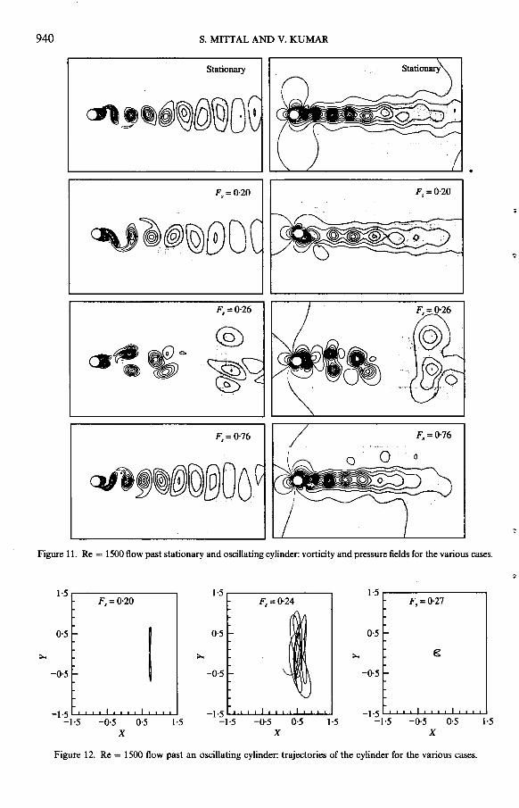
both the flows. The top row in Figure 11 shows the vorticity and pressure fields at one timeinstant for the temporally periodic solution. The rest of the rows in this figure showsolutions for the oscillating cylinder. The second row shows the flow field for F. = 0.20. As .a result of the cylinder motion the lateral width of the wake increases and the vortex-shedding frequency decreases as is suggested by the increased longitudinal spacing betweenthe vortices. The time histories for the aerodynamic coefficients and displacements of thecylinder are shown in Figure 10. The trajectory of the cylinder is shown in Figure 12. Thecylinder undergoes large amplitude cross-flow vibrations and relatively low amplitudein-line oscillations. Its trajectory resembles a Lissajous figure of 8. The Strouhal numbercorresponding to the vortex-shedding frequency is 0.22. As was the case for F. = 0,20,Re = 1000 the vortex-shedding frequency is larger than the structural frequency but smallerthan F. and larger than Fo. The third row in Figure 11 shows the flow field for the oscillatingcylinder for F. = 0.26 at t = 363. The related time histories are shown in Figure 10 and thetrajectory of the cylinder in Figure 12. This case is very interesting from the point of view ofcompetition between various modes of vortex shedding. The third row in Figure 11,corresponding to t = 363, shows the Symmetric mode S of vortex shedding. However, the
FLOW-INDUCED VIBRATIONS 939
4,0 [:::::::::J 2.0~ill~~illW~~ Stationary 3,0 8 d 0,0 2.01.0 -2,00 20 40 60 80 100 120 0 20 40 60 80 100 1204,0~::::::::J 2.0~~~~~::3 F = 0.20 3'0 . Q ...J00U U .2.01.0 -2,0
50 100 150 200 250 50 100 150 200 250
1 . 0~:~~~~~~~~~ ~~~~~~~ F. = 0.20 1.5 ,
>< 0,5 >-. 0'0
-1,5
0'0
50 100 150 200 250 50 100 150 200 250
4,0~~~~~;~~ 2.0~b~~~jl~~ F = 0.26 3,0 . 8 d 0,02.01.0 -2,0
150 200 250 300 350 150 200 250 300 350
1 ,0~~~~~~~~~~~~~~~~ F. = 0.26 1.5>< 0,5 >-. 0,0-1,50,0150 200 250 300 350 150 200 250 300 3503'5, = 0,7 2.02.58 d 0,01.50.5 -2,0100 150 200 250 300 100 150 200 250 3000,5E::::::::~[:::=====:::3 F,=0'76 1.5 >< 0.0 >-. 0,0-1,5-0,5100 150 200 250 300 100 150 200 250 300Figure 10. Re = 1500 flow past a stationary and oscillating cylinder: time histories of the drag and liftcoefficients and normalized cylinder displacements.pictures at some other time instants (not shown here) display the Antisymmetrical modeA-III of vortex shedding. This can also be observed from the time histories of the liftcoefficient and cross-flow displacement of the cylinder in Figure 10. For example, for320 < t < 350 (anti-symmetric shedding), approximately, the amplitude of the temporalvariation of lift coefficient is quite large compared to that for 300 < t < 320 and t > 350(symmetric shedding). Similarly, the cross-flow oscillations during 300 < t < 320 and
940 S. MITTAL AND V. KUMAR
Stationary
~J,~~(Q)~Ot.
Fa = Q-20
~~~\9)(i)O ...
F =0,26 F =0.26a a
@CS~~c. ~ t~
Fa=0'76 Fa = 0,76
!
c!J},~{tf))lO)@OO
Figure 11. Re = 1500 flow past stationary and oscillating cylinder: vorticity and pressure fields for the various cases.
1.5 1.5 1.5F =0,20 F =0,27a a
0,5 0,5 0'5
>.. >.. >.. g
-0.5 -0,5 -0,5
-1,5 -1,5 -1,5-1,5 -0,5 0,5 1.5 -1,5 -0,5 0,5 1.5 -1,5 -0.5 0,5 1.5
X X X
Figure 12. Re = 1500 flow past an oscillating cylinder: trajectories of the cylinder for the various cases.
FLOW-INDUCED VIBRATIONS 941
4.0r~~'i3~~~~ 2.0~~~IMI~ Stationarye 2.0 d 0.00.0 -2.0
0 50 100 ISO 200 0 50 100 ISO 200
4.0r~.~:;y~~1 3.0~~ e 2.0 d 0.0F, = 0.25
0.0 -3.0
700 750 800 850 900 700 750 800 850 900~~1.5 1.2 >< ~ 0.00.5 F, = 0.25 M ~ ~ "II fi, , A A A II 1\ n II A A j
-1.5r,~v, ~~,V,V~VIV,~~~ :~~ ,v, VI
700 750 800 850 900 700 750 800 850 9004.0V~~~;~~1 3.0~~~~~~~ F, = 0.50 1.0 e 2.0 d
-1.0
0.0 -3.0
600 650 700 750 800 600 650 700 750 800
I . 0~~~~;;~d I . 5E=:::::~::3 F = 0.50 >< 0.3 ' ~ 0.0-0.4 -1.5
600 650 700 750 800 600 650 700 750 8004.0~~:Y~t~~ 3.0~~~fu\~fNy1e 2.0 d 0.0
F,=0.50,M=10.0 -3.0
100 150 200 250 300 100 ISO 200 250 3001.4~~~~~d~~ 1.5~\~~v\~MA1 >< 0.7 ~ 0.0
F,=0.50,M= I
0.0 -1.5
100 150 200 250 300 100 150 200 250 300
4.0~~~~~i'!~I1\~ = 0.60 3.0 ~~~~~~~~ e 2.0 ' d 0.0
0.0 -3.0250 300 350 400 450 250 300 350 400 450
1.0~~;;~~;;j 1.5E====::::] F = 0.60 >< 0.3 ' ~ 0.0-0.4 -1.5
250 300 350 400 450 250 300 350 400 450
Figure 13. Re = 104 flow past a stationary and oscillating cylinder: time histories of the drag and lift coefficientsand normalized cylinder displacements.
942 S. MITTAL AND V. KUMAR
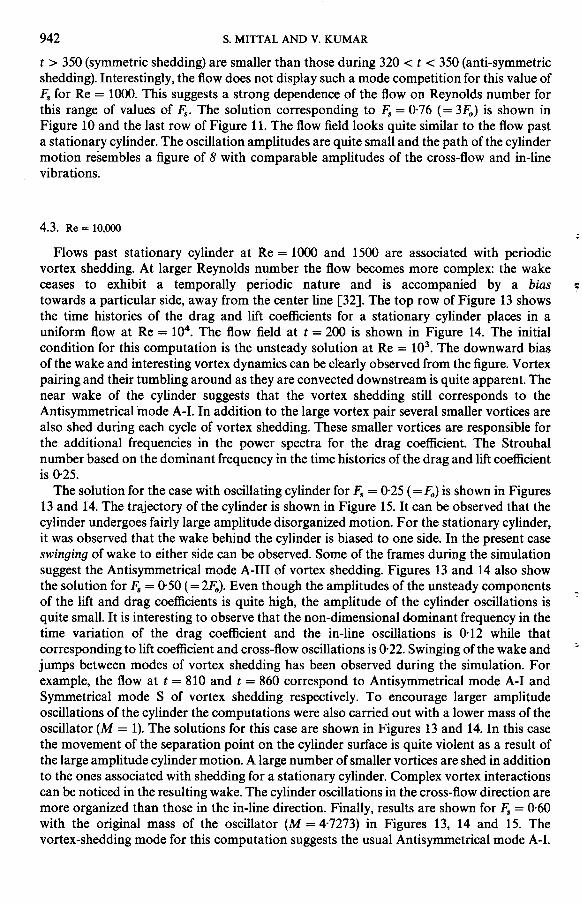
t > 350 (symmetric shedding) are smaller than those during 320 < t < 350 (anti-symmetricshedding). Interestingly, the flow does not display such a mode competition for this value ofF. for Re = 1000. This suggests a strong dependence of the flow on Reynolds number forthis range of values of F.. The solution corresponding to F. = 0.76 (= 3Fo) is shown inFigure 10 and the last row of Figure 11. The flow field looks quite similar to the flow pasta stationary cylinder. The oscillation amplitudes are quite small and the path of the cylindermotion resembles a figure of 8 with comparable amplitudes of the cross-flow and in-linevibrations.
4.3. Re = 10,000 .
Flows past stationary cylinder at Re = 1000 and 1500 are associated with periodicvortex shedding. At larger Reynolds number the flow becomes more complex: the wakeceases to exhibit a temporally periodic nature and is accompanied by a bias ~
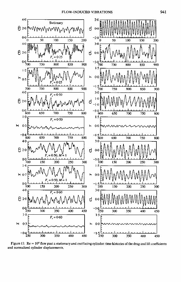
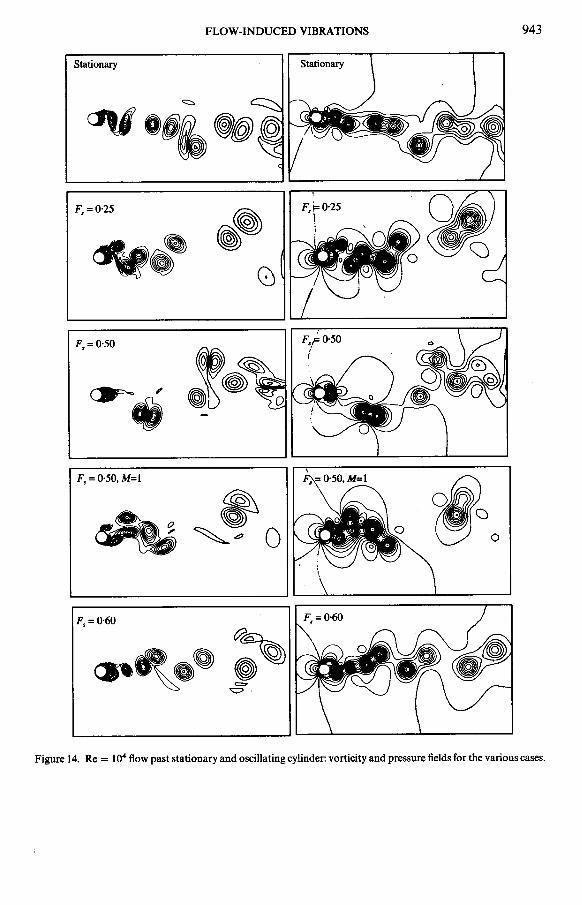
towards a particular side, away from the center line [32]. The top row of Figure 13 showsthe time histories of the drag and lift coefficients for a stationary cylinder places in auniform flow at Re = 104. The flow field at t = 200 is shown in Figure 14. The initialcondition for this computation is the unsteady solution at Re = 103. The downward bias
of the wake and interesting vortex dynamics can be cl~arly observed from the figure. Vortexpairing and their tumbling around as they are convected downstream is quite apparent. Thenear wake of the cylinder suggests that the vortex shedding still corresponds to theAntisymmetrical mode A-I. In addition to the large vortex pair several smaller vortices arealso shed during each cycle of vortex shedding. These smaller vortices are responsible forthe additional frequencies in the power spectra for the drag coefficient. The Strouhalnumber based on the dominant frequency in the time histories of the drag and lift coefficientis 0.25.
The solution for the case with oscillating cylinder for F. = 0.25 (=Fo) is shown in Figures
13 and 14. The trajectory of the cylinder is shown in Figure 15. It can be observed that thecylinder undergoes fairly large amplitude disorganized motion. For the stationary cylinder,it was observed that the wake behind the cylinder is biased to one side. In the present caseswinging of wake to either side can be observed. Some of the frames during the simulationsuggest the Antisymmetrical mode A-III of vortex shedding. Figures 13 and 14 also showthe solution for F. = 0.50 (= 2Fo). Even though the amplitudes of the unsteady components -of the lift and drag coefficients is quite high, the amplitude of the cylinder oscillations is '
quite small. It is interesting to observe that the non-dimensional dominant frequency in thetime variation of the drag coefficient and the in-line oscillations is 0.12 while thatcorresponding to lift coefficient and cross-flow oscillations is 0.22. Swinging of the wake and :.
jumps between modes of vortex shedding has been observed during the simulation. Forexample, the flow at t = 810 and t = 860 correspond to Antisymmetrical mode A-I andSymmetrical mode S of vortex shedding respectively. To encourage larger amplitudeoscillations of the cylinder the computations were also carried out with a lower mass of theoscillator (M = 1). The solutions for this case are shown in Figures 13 and 14. In this casethe movement of the separation point on the cylinder surface is quite violent as a result ofthe large amplitude cylinder motion. A large number of smaller vortices are shed in additionto the ones associated with shedding for a stationary cylinder. Complex vortex interactionscan be noticed in the resulting wake. The cylinder oscillations in the cross-flow direction aremore organized than those in the in-line direction. Finally, results are shown for F. = 0.60with the original mass of the oscillator (M = 4.7273) in Figures 13, 14 and 15. The
vortex-shedding mode for this computation suggests the usual Antisymmetrical mode A-I.
FLOW-INDUCED VIBRATIONS 943
Stationary Stationary
~
~ .'i ~I
F,=0-25 ~~ft}. ~
riQi) a
F = 0,50
'~. :F'=:;;;" ~ . olio\..'~\~~~~ ~ ~ 0 ~' 0
F = 0,60, ~~~.o ,~
"=='
Figure 14. Re = 104 flow past stationary and oscillating cylinder: vorticity and pressure fields for the various cases.
944 S. MITTAL AND V. KUMAR
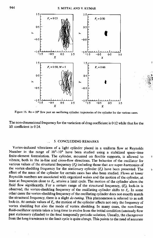
1.5 1.5F =0,25 F =0.50s s
O' 0,5
>.. >.. t-0. -0,5
-1,5 -1,5-1,5 -0,5 0'5 1.5 -1,5 -0,5 0,5 1.5
X X
1.5 1.5 .F =0,50 M= 1 F =0,60s , s
O' O'
>.. >...
-0' -0'
-1,5 -1,5-1,5 -0,5 0,5 1.5 -1,5 -0,5 0,5 1.5
X X
Figure 15. Re = 104 flow past an oscillating cylinder: trajectories of the cylinder for the various cases.
The non-dimensional frequency for the variation of drag coefficient is 0.12 while that for thelift coefficient is 0.24.
5. CONCLUDING REMARKS
Vortex-induced vibrations of a light cylinder placed in a uniform flow at ReynoldsNumber in the range of 103-104 have been studied using a stabilized space-timefinite-element formulation. The cylinder, mounted on flexible supports, is allowed to .-;
vibrate, both in the in-line and cross-flow directions. The behavior of the oscillator forvarious values of the structural frequency (F.) including those that are super-harmonics ofthe vortex-shedding frequency for the stationary cylinder (Fa) have been presented. The ~
effect of the mass of the cylinder for certain cases has also been studied. Flows at lowerReynolds numbers are associated with organized wakes and the motion of the cylinder, atleast at frequencies close to Fa, attains a limit cycle. The motion of the cylinder alters thefluid flow significantly. For a certain range of the structural frequency, (F.), lock-in isobserved; the vortex-shedding frequency of the oscillating cylinder shifts to F.. In someother cases the vortex-shedding frequency of the oscillating cylinder does not exactly matchthe structural frequency; there is a slight de-tuning. This phenomenon is referred to as softlock-in. At certain values of F., the motion of the cylinder affects not only the frequency ofvortex shedding but also the mode of vortex shedding. In many cases, the non-linearfluid-oscillator system takes a long time to evolve from the initial condition (unsteady flowpast stationary cylinder) to the final temporally periodic solution. Usually, the changeoverfrom the long transience to the limit cycle is quite abrupt. This points to the need of accurate
FLOW-INDUCED VIBRATIONS 945
long-time integration of the governing equations to study the dynamics of such non-linear
systems. At higher Reynolds numbers, the vortex shedding is quite disorganized and the
cylinder does not reach a temporally periodic solution. The vortex dynamics in the wake is
extremely complex and so is its effect on the motion of the cylinder. High Reynolds number
flows, past stationary cylinders, are associated with wakes with a bias; the entire wake isdeflected to one side, away from the center line. For oscillating cylinders, in certain cases,swinging of wake from side-to-side, around the center line and mode competition between
various modes of vortex shedding is observed. Some of these features of the non-linear
fluid-structure interaction are quite sensitive to the Reynolds numbers. The trajectory of
the oscillating cylinder shows very interesting patterns including the well-known Lissajou
figure of 8. Several mechanisms of the non-linear oscillator for self-limiting its vibration
amplitude are observed. As the vibration amplitude increases, the flow changes and so do
the aerodynamic forces acting on the cylinder, to limit the amplitude of oscillations. The.
phenomenon of soft lock-in is also a mechanism of the oscillator to self-limit its oscillation
amplitude and is typically observed for light cylinders that exhibit high-amplitude
vibrations.
ACKNOWLEDGMENTS
Partial support for this work has come from the Department of Science and Technology,
India under the project number DST -AE-95279 with Department of Aerospace
Engineering, liT, Kanpur.
REFERENCES
1. G. H. KOOPMANN 1967 Journal of Fluid Mechanics 28,501-512. The vortex wakes of vibrationcylinders at low Reynolds numbers.
2. O. M. GRIFFIN, R. A. SKOP and G. H. KOOPMANN 1973 Journal of Fluid Mechanics 54, 235-249.The vortex-excited resonant vibrations of circular cylinders.
3. T. SARPKAYA 1979 Journal of Applied Mechanics 46, 241-258. Vortex-induced oscillations:a selective review.
4. G. H. TOEBES 1969 Journal of Basic Engineering 91, 493-505. The unsteady flow and wake near anoscillating cylinder.
5. O. M. GRIFFIN 1971 Journal of Applied Mechanics 38, 729-738. The unsteady wake of anoscillating cylinder at low Reynolds number.
6. Y. TANIDA, A. OKAJIMA and Y. WATANABE 1973 Journal of Fluid Mechanics 61,769- 784. Stabilityof a circular cylinder in uniform flow or in a wake.
7. O. M. GRIFFIN and S. E. RAMBERG 1975 Journal of Fluid Mechanics 75, 257-271. Vortex sheddingfrom a cylinder vibrating in line with an incident uniform flow.
8. R. KING 1977 Ocean Engineering 4, 141-171. A review of vortex shedding research and its
application.9. W. W. DURGIN, P. A. MARCH and P. J. LEFEBVRE 1980 Journal of Fluids Engineering,
Transactions of the American Society of Mechanical Engineers 102, 183-190. Lower mode responseof circular cylinders in cross-flow.
10. Y. LECOINTE, J. PIQUET and J. PLANTEC 1987 In Forum on Unsteady Flow Separation (K. N. Ghia,editor), FED-52, 147-157. American Society of Mechanical Engineers. Flow structure in the wakeof an oscillating cylinder.
11. S. S. CHEN 1987 Flow-Induced Vibrations of Circular Cylindrical Structures. New York:
Hemisphere Publishing Corporation.12. C. H. K. WILLIAMSON and A. ROSHKO 1988 Journal of Fluids and Structures 2, 355-381. Vortex
formation in the wake of an oscillating cylinder.13. D. J. OLINGER and K. R. SREENIVASAN 1988 Physical Review Letters 60, 797-800. Nonlinear
dynamics of the wake of an oscillating cylinder.
946 s. MITTAL AND V. KUMAR
14. A. ONGOREN and D. ROCKWELL 1988 Journal of Fluid Mechanics 191, 197-223. Flow structurefrom an oscillating cylinder Part 1. Mechanisms of phase shift and recovery in the near wake.
15. A. ONGOREN and D. ROCKWELL 1988 Journal of Fluid Mechanics 191, 225-245. Flow structurefrom an oscillating cylinder Part 2. Mode competition in the near wake.
16. R. D. BLEVINS 1990 Flow-Induced Vibration. New York: Van Nostrand Reinhold.17. S. MITrAL and T. E. TEZDUYAR 1992 International Journalfor Numerical Methods in Fluids 15,
1073-1118. A finite element study of incompressible flows past oscillating cylinders and airfoils.18. S. MITrAL, A. RATNER, D. HASTREITER and T. E. TEZDUYAR 1991 International Video Journal of
Engineering Research 1, 83-96. Space-time finite element computation of incompressible flowswith emphasis on flows involving oscillating cylinders.
19. K. S. CHANG and J. Y. SA 1992 American Institute of Aeronautics and Astronautics Journal 30,1331-1336. Patterns of vortex shedding from an oscillating circular cylinder.
20. S. MITrAL and V. KUMAR 1999 International Journal for Numerical Methods in Fluids 31,1087-1120. Finite element study of vortex-induced cross-flow and in-line oscillations of a circular ;-cylinder at low Reynolds numbers.
21. T. E. TEZDUYAR, M. BEHR and J. LIOU 1992 Computer Methods in Applied Mechanics and 1"
Engineering 94, 339-351. A new strategy for finite element computations involving moving ~boundaries and interfaces-the deforming-spatial-domainjspace-time procedure: I. The concept ~,and the preliminary tests. ~
22. T. E. TEZDUYAR, M. BEHR, S. MITrAL and J. LIOU 1992 Computer Methods in Applied Mechanicsand Engineering 94, 353-371. A new strategy for finite element computations involvingmoving boundaries and interfaces-the deforming-spatial-domainjspace-time procedure: II.Computation of free-surface flows, two-liquid flows, and flows with drifting cylinders.
23. Y. SAAD and M. SCHULTZ 1986 SIAM Journal of Scientific and Statistical Computing 7, 856-869.GMRES: a generalized minimal residual algorithm for solving nonsymmetric linear systems.
24. T. E. TEZDUYAR, S. MITrAL, S. E. RAY and R. SHIH 1992 Computer Methods in Applied Mechanicsand Engineering 95, 221-242. Incompressible flow computations with stabilized bilinear andlinear equal-order-interpolation velocity-pressure elements.
25. S. MITrAL 1992 Ph.D. thesis, University of Minnesota. Stabilized space-time finite elementformulations for unsteady incompressible flows. Involving fluid-body interactions.
26. H. SCHLICHTING 1979 Boundary-Layer Theory. New York: McGraw-Hill. Seventh edition.27. S. BALACHANDAR and R. MITrAL 1996 Role of three-dimensionality in the near wake of
two-dimensional cylinders. In Mechanics and Thermal Sciences (T. S. Mruthyunjaya, editor),Advances in Mechanical Engineering-Vol. II, 1385-1395, Indian Institute of Science Bangalore,India: Narosa Publishing House.
28. V. KALRO and T. TEZDUYAR 1995 Parallel finite element computation of 3D incompressible flowson MPPs. In Solution Techniques For Large-Scale CFD Problems (W. G. Habashi, editor),Computational Methods in Applied Sciences, New York: Wiley.
29. S. MITrAL 2001 Physics of Fluids 13,177-191. Computation of three-dimensional flows pastcircular cylinder of low aspect-ratio.
30. C. H. K. WILLIAMSON 1996 Annual Review of Fluid Mechanics 28, 477-539. Vortex dynamics in -the cylinder wake. '
31. O. M. GRIFFIN and S. E. RAMBERG 1982 Journal of Energy Resources Technology, Transactions ofthe American Society of Mechanical Engineers 104, 2-13. Some recent studies of vortex shedding ..
with application to marine tubulars and risers. ,~32. M. BEHR 1992 Ph.D. thesis, Department of Aerospace Engineering, University of Minnesota.
Stabilized finite element methods for incompressible flows with emphasis on moving boundariesand interfaces.