Embed Size (px)
Citation preview
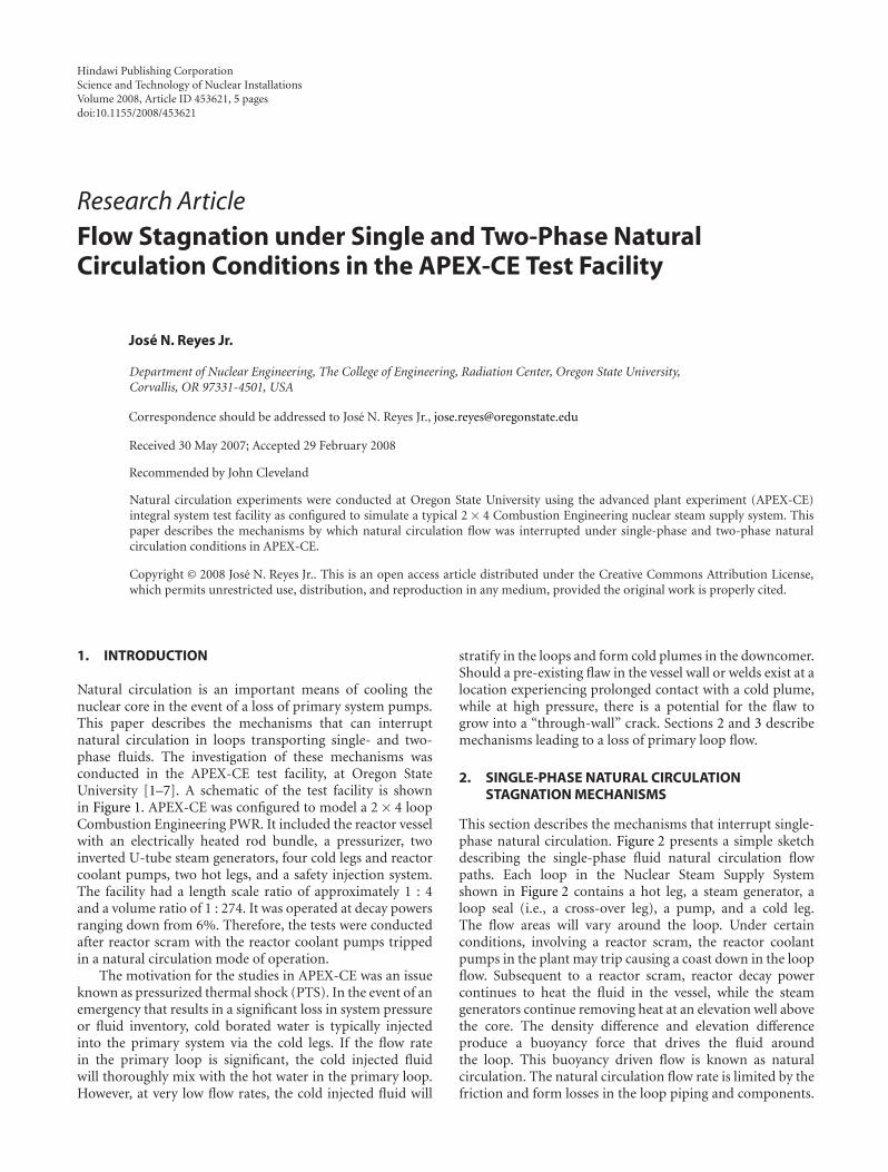
Hindawi Publishing CorporationScience and Technology of Nuclear InstallationsVolume 2008, Article ID 453621, 5 pagesdoi:10.1155/2008/453621
Research ArticleFlow Stagnation under Single and Two-Phase NaturalCirculation Conditions in the APEX-CE Test Facility
Jose N. Reyes Jr.
Department of Nuclear Engineering, The College of Engineering, Radiation Center, Oregon State University,Corvallis, OR 97331-4501, USA
Correspondence should be addressed to Jose N. Reyes Jr., [email protected]
Received 30 May 2007; Accepted 29 February 2008
Recommended by John Cleveland
Natural circulation experiments were conducted at Oregon State University using the advanced plant experiment (APEX-CE)integral system test facility as configured to simulate a typical 2 × 4 Combustion Engineering nuclear steam supply system. Thispaper describes the mechanisms by which natural circulation flow was interrupted under single-phase and two-phase naturalcirculation conditions in APEX-CE.
Copyright © 2008 Jose N. Reyes Jr.. This is an open access article distributed under the Creative Commons Attribution License,which permits unrestricted use, distribution, and reproduction in any medium, provided the original work is properly cited.
1. INTRODUCTION
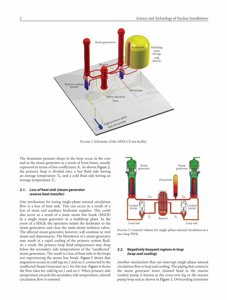
Natural circulation is an important means of cooling thenuclear core in the event of a loss of primary system pumps.This paper describes the mechanisms that can interruptnatural circulation in loops transporting single- and two-phase fluids. The investigation of these mechanisms wasconducted in the APEX-CE test facility, at Oregon StateUniversity [1–7]. A schematic of the test facility is shownin Figure 1. APEX-CE was configured to model a 2 × 4 loopCombustion Engineering PWR. It included the reactor vesselwith an electrically heated rod bundle, a pressurizer, twoinverted U-tube steam generators, four cold legs and reactorcoolant pumps, two hot legs, and a safety injection system.The facility had a length scale ratio of approximately 1 : 4and a volume ratio of 1 : 274. It was operated at decay powersranging down from 6%. Therefore, the tests were conductedafter reactor scram with the reactor coolant pumps trippedin a natural circulation mode of operation.
The motivation for the studies in APEX-CE was an issueknown as pressurized thermal shock (PTS). In the event of anemergency that results in a significant loss in system pressureor fluid inventory, cold borated water is typically injectedinto the primary system via the cold legs. If the flow ratein the primary loop is significant, the cold injected fluidwill thoroughly mix with the hot water in the primary loop.However, at very low flow rates, the cold injected fluid will
stratify in the loops and form cold plumes in the downcomer.Should a pre-existing flaw in the vessel wall or welds exist at alocation experiencing prolonged contact with a cold plume,while at high pressure, there is a potential for the flaw togrow into a “through-wall” crack. Sections 2 and 3 describemechanisms leading to a loss of primary loop flow.
2. SINGLE-PHASE NATURAL CIRCULATIONSTAGNATION MECHANISMS
This section describes the mechanisms that interrupt single-phase natural circulation. Figure 2 presents a simple sketchdescribing the single-phase fluid natural circulation flowpaths. Each loop in the Nuclear Steam Supply Systemshown in Figure 2 contains a hot leg, a steam generator, aloop seal (i.e., a cross-over leg), a pump, and a cold leg.The flow areas will vary around the loop. Under certainconditions, involving a reactor scram, the reactor coolantpumps in the plant may trip causing a coast down in the loopflow. Subsequent to a reactor scram, reactor decay powercontinues to heat the fluid in the vessel, while the steamgenerators continue removing heat at an elevation well abovethe core. The density difference and elevation differenceproduce a buoyancy force that drives the fluid aroundthe loop. This buoyancy driven flow is known as naturalcirculation. The natural circulation flow rate is limited by thefriction and form losses in the loop piping and components.
2 Science and Technology of Nuclear Installations
Pressurizer
Reactor
Steam generators
Break line
Reactor coolantpumps
Safety injectionlines
High pressure safety
injection pump
Refuelingwater
storagetank
(RWST)
Figure 1: Schematic of the APEX-CE test facility.
The dominant pressure drops in the loop occur in the coreand in the steam generator as a result of form losses, usuallyexpressed in terms of loss coefficients, K . As shown Figure 2,the primary loop is divided into: a hot fluid side havingan average temperature TH and a cold fluid side having anaverage temperature TC .
2.1. Loss of heat sink (steam generatorreverse heat transfer)
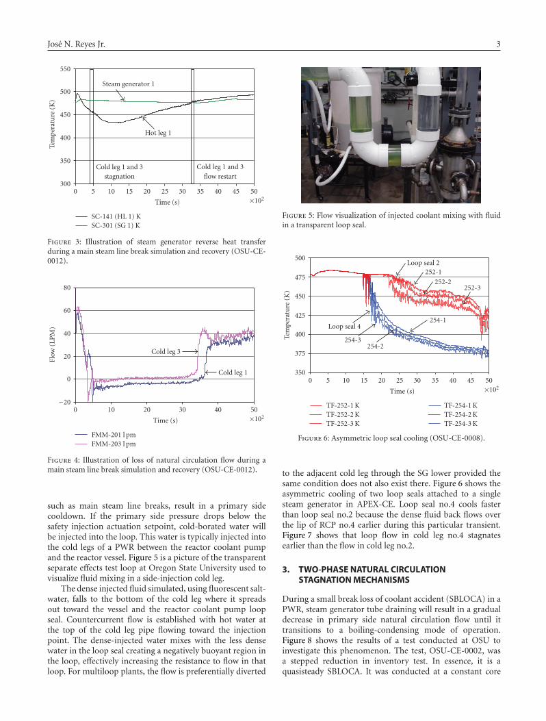
One mechanism for losing single-phase natural circulationflow is a loss of heat sink. This can occur as a result of aloss of main and auxiliary feedwater supplies. This couldalso occur as a result of a main steam line break (MSLB)in a single steam generator in a multiloop plant. In theevent of a MSLB, the operators isolate the feedwater to thesteam generators and close the main steam isolation valves.The affected steam generator, however, will continue to ventsteam and depressurize. The blowdown of a steam generatormay result in a rapid cooling of the primary system fluid.As a result, the primary loop fluid temperatures may dropbelow the secondary side temperatures of the “unaffected”steam generators. The result is a loss of heat sink in the loopsnot experiencing the steam line break. Figure 3 shows thatstagnation occurs in cold legs no.1 and no.3, connected to theunaffected Steam Generator no.1 for this test. Figure 4 showsthe flow rates for cold leg no.1 and no.3. When primary sidetemperature exceeds the secondary side temperature, naturalcirculation flow is restored.
Pressurizer
Reactor
Loop seal Loop seal
TH TH
TCTC
Steamgenerator
Steamgenerator
Coolantpump
Coolantpump
Figure 2: Control volume for single-phase natural circulation in atwo-loop PWR.
2.2. Negatively buoyant regions in loop(loop seal cooling)
Another mechanism that can interrupt single-phase naturalcirculation flow is loop seal cooling. The piping that connectsthe steam generator lower channel head to the reactorcoolant pump is known as the cross-over leg or the reactorpump loop seal as shown in Figure 2. Overcooling transients
Jose N. Reyes Jr. 3
300
350
400
450
500
550
Tem
per
atu
re(K
)
0 5 10 15 20 25 30 35 40 45 50×102
Time (s)
Cold leg 1 and 3flow restart
Cold leg 1 and 3stagnation
Steam generator 1
Hot leg 1
SC-141 (HL 1) KSC-301 (SG 1) K
Figure 3: Illustration of steam generator reverse heat transferduring a main steam line break simulation and recovery (OSU-CE-0012).
−20
0
20
40
60
80
Flow
(LP
M)
0 10 20 30 40 50×102
Time (s)
Cold leg 3
Cold leg 1
FMM-201 l pmFMM-203 l pm
Figure 4: Illustration of loss of natural circulation flow during amain steam line break simulation and recovery (OSU-CE-0012).
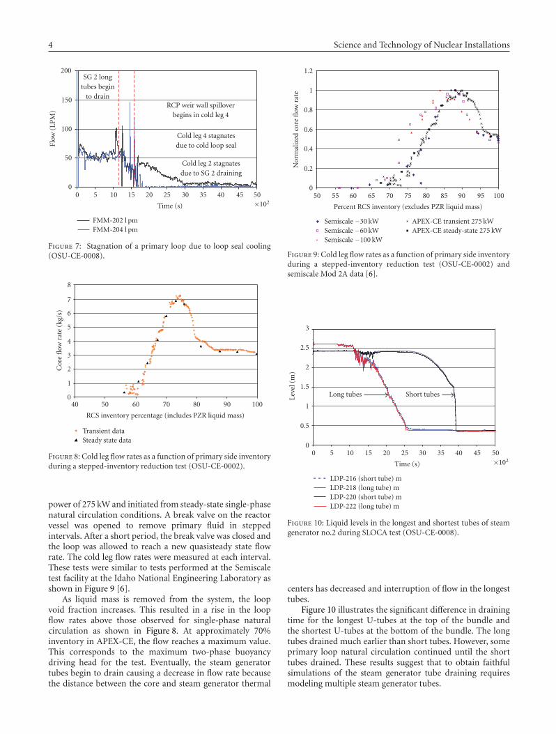
such as main steam line breaks, result in a primary sidecooldown. If the primary side pressure drops below thesafety injection actuation setpoint, cold-borated water willbe injected into the loop. This water is typically injected intothe cold legs of a PWR between the reactor coolant pumpand the reactor vessel. Figure 5 is a picture of the transparentseparate effects test loop at Oregon State University used tovisualize fluid mixing in a side-injection cold leg.
The dense injected fluid simulated, using fluorescent salt-water, falls to the bottom of the cold leg where it spreadsout toward the vessel and the reactor coolant pump loopseal. Countercurrent flow is established with hot water atthe top of the cold leg pipe flowing toward the injectionpoint. The dense-injected water mixes with the less densewater in the loop seal creating a negatively buoyant region inthe loop, effectively increasing the resistance to flow in thatloop. For multiloop plants, the flow is preferentially diverted
Figure 5: Flow visualization of injected coolant mixing with fluidin a transparent loop seal.
350
375
400
425
450
475
500
Tem
per
atu
re(K
)
0 5 10 15 20 25 30 35 40 45 50×102
Time (s)
Loop seal 2
Loop seal 4
252-1
252-2252-3
254-1
254-2254-3
TF-252-1 KTF-252-2 KTF-252-3 K
TF-254-1 KTF-254-2 KTF-254-3 K
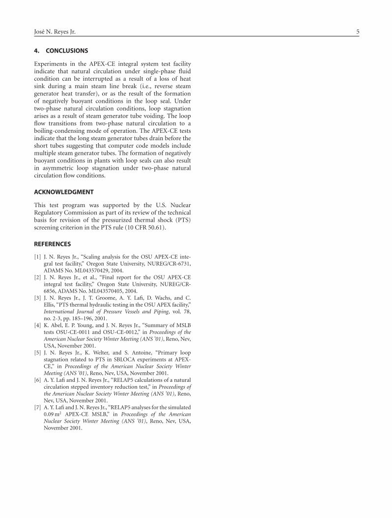
Figure 6: Asymmetric loop seal cooling (OSU-CE-0008).
to the adjacent cold leg through the SG lower provided thesame condition does not also exist there. Figure 6 shows theasymmetric cooling of two loop seals attached to a singlesteam generator in APEX-CE. Loop seal no.4 cools fasterthan loop seal no.2 because the dense fluid back flows overthe lip of RCP no.4 earlier during this particular transient.Figure 7 shows that loop flow in cold leg no.4 stagnatesearlier than the flow in cold leg no.2.
3. TWO-PHASE NATURAL CIRCULATIONSTAGNATION MECHANISMS
During a small break loss of coolant accident (SBLOCA) in aPWR, steam generator tube draining will result in a gradualdecrease in primary side natural circulation flow until ittransitions to a boiling-condensing mode of operation.Figure 8 shows the results of a test conducted at OSU toinvestigate this phenomenon. The test, OSU-CE-0002, wasa stepped reduction in inventory test. In essence, it is aquasisteady SBLOCA. It was conducted at a constant core
4 Science and Technology of Nuclear Installations
0
50
100
150
200
Flow
(LP
M)
0 5 10 15 20 25 30 35 40 45 50×102
Time (s)
SG 2 longtubes begin
to drainRCP weir wall spillover
begins in cold leg 4
Cold leg 4 stagnatesdue to cold loop seal
Cold leg 2 stagnatesdue to SG 2 draining
FMM-202 l pmFMM-204 l pm
Figure 7: Stagnation of a primary loop due to loop seal cooling(OSU-CE-0008).
0
1
2
3
4
5
6
7
8
Cor
efl
owra
te(k
g/s)
40 50 60 70 80 90 100
RCS inventory percentage (includes PZR liquid mass)
Transient dataSteady state data
Figure 8: Cold leg flow rates as a function of primary side inventoryduring a stepped-inventory reduction test (OSU-CE-0002).
power of 275 kW and initiated from steady-state single-phasenatural circulation conditions. A break valve on the reactorvessel was opened to remove primary fluid in steppedintervals. After a short period, the break valve was closed andthe loop was allowed to reach a new quasisteady state flowrate. The cold leg flow rates were measured at each interval.These tests were similar to tests performed at the Semiscaletest facility at the Idaho National Engineering Laboratory asshown in Figure 9 [6].
As liquid mass is removed from the system, the loopvoid fraction increases. This resulted in a rise in the loopflow rates above those observed for single-phase naturalcirculation as shown in Figure 8. At approximately 70%inventory in APEX-CE, the flow reaches a maximum value.This corresponds to the maximum two-phase buoyancydriving head for the test. Eventually, the steam generatortubes begin to drain causing a decrease in flow rate becausethe distance between the core and steam generator thermal
0
0.2
0.4
0.6
0.8
1
1.2
Nor
mal
ized
core
flow
rate
50 55 60 65 70 75 80 85 90 95 100
Percent RCS inventory (excludes PZR liquid mass)
Semiscale −30 kWSemiscale −60 kWSemiscale −100 kW
APEX-CE transient 275 kWAPEX-CE steady-state 275 kW
Figure 9: Cold leg flow rates as a function of primary side inventoryduring a stepped-inventory reduction test (OSU-CE-0002) andsemiscale Mod 2A data [6].
0
0.5
1
1.5
2
2.5
3
Leve
l(m
)
0 5 10 15 20 25 30 35 40 45 50×102
Time (s)
Long tubes Short tubes
LDP-216 (short tube) mLDP-218 (long tube) mLDP-220 (short tube) mLDP-222 (long tube) m
Figure 10: Liquid levels in the longest and shortest tubes of steamgenerator no.2 during SLOCA test (OSU-CE-0008).
centers has decreased and interruption of flow in the longesttubes.
Figure 10 illustrates the significant difference in drainingtime for the longest U-tubes at the top of the bundle andthe shortest U-tubes at the bottom of the bundle. The longtubes drained much earlier than short tubes. However, someprimary loop natural circulation continued until the shorttubes drained. These results suggest that to obtain faithfulsimulations of the steam generator tube draining requiresmodeling multiple steam generator tubes.
Jose N. Reyes Jr. 5
4. CONCLUSIONS
Experiments in the APEX-CE integral system test facilityindicate that natural circulation under single-phase fluidcondition can be interrupted as a result of a loss of heatsink during a main steam line break (i.e., reverse steamgenerator heat transfer), or as the result of the formationof negatively buoyant conditions in the loop seal. Undertwo-phase natural circulation conditions, loop stagnationarises as a result of steam generator tube voiding. The loopflow transitions from two-phase natural circulation to aboiling-condensing mode of operation. The APEX-CE testsindicate that the long steam generator tubes drain before theshort tubes suggesting that computer code models includemultiple steam generator tubes. The formation of negativelybuoyant conditions in plants with loop seals can also resultin asymmetric loop stagnation under two-phase naturalcirculation flow conditions.
ACKNOWLEDGMENT
This test program was supported by the U.S. NuclearRegulatory Commission as part of its review of the technicalbasis for revision of the pressurized thermal shock (PTS)screening criterion in the PTS rule (10 CFR 50.61).
REFERENCES
[1] J. N. Reyes Jr., “Scaling analysis for the OSU APEX-CE inte-gral test facility,” Oregon State University, NUREG/CR-6731,ADAMS No. ML043570429, 2004.
[2] J. N. Reyes Jr., et al., “Final report for the OSU APEX-CEintegral test facility,” Oregon State University, NUREG/CR-6856, ADAMS No. ML043570405, 2004.
[3] J. N. Reyes Jr., J. T. Groome, A. Y. Lafi, D. Wachs, and C.Ellis, “PTS thermal hydraulic testing in the OSU APEX facility,”International Journal of Pressure Vessels and Piping, vol. 78,no. 2-3, pp. 185–196, 2001.
[4] K. Abel, E. P. Young, and J. N. Reyes Jr., “Summary of MSLBtests OSU-CE-0011 and OSU-CE-0012,” in Proceedings of theAmerican Nuclear Society Winter Meeting (ANS ’01), Reno, Nev,USA, November 2001.
[5] J. N. Reyes Jr., K. Welter, and S. Antoine, “Primary loopstagnation related to PTS in SBLOCA experiments at APEX-CE,” in Proceedings of the American Nuclear Society WinterMeeting (ANS ’01), Reno, Nev, USA, November 2001.
[6] A. Y. Lafi and J. N. Reyes Jr., “RELAP5 calculations of a naturalcirculation stepped inventory reduction test,” in Proceedings ofthe American Nuclear Society Winter Meeting (ANS ’01), Reno,Nev, USA, November 2001.
[7] A. Y. Lafi and J. N. Reyes Jr., “RELAP5 analyses for the simulated0.09 m2 APEX-CE MSLB,” in Proceedings of the AmericanNuclear Society Winter Meeting (ANS ’01), Reno, Nev, USA,November 2001.

TribologyAdvances in
Hindawi Publishing Corporationhttp://www.hindawi.com Volume 2014
International Journal of
AerospaceEngineeringHindawi Publishing Corporationhttp://www.hindawi.com Volume 2010
FuelsJournal of
Hindawi Publishing Corporationhttp://www.hindawi.com Volume 2014
Journal ofPetroleum Engineering
Hindawi Publishing Corporationhttp://www.hindawi.com Volume 2014
Industrial EngineeringJournal of
Hindawi Publishing Corporationhttp://www.hindawi.com Volume 2014
Power ElectronicsHindawi Publishing Corporationhttp://www.hindawi.com Volume 2014
Advances in
CombustionJournal of
Hindawi Publishing Corporationhttp://www.hindawi.com Volume 2014
Journal of
Hindawi Publishing Corporationhttp://www.hindawi.com Volume 2014
Renewable Energy
Submit your manuscripts athttp://www.hindawi.com
Hindawi Publishing Corporationhttp://www.hindawi.com Volume 2014
StructuresJournal of
International Journal of
RotatingMachinery
Hindawi Publishing Corporationhttp://www.hindawi.com Volume 2014
EnergyJournal of
Hindawi Publishing Corporationhttp://www.hindawi.com Volume 2014
Hindawi Publishing Corporation http://www.hindawi.com
Journal ofEngineeringVolume 2014
Hindawi Publishing Corporation http://www.hindawi.com Volume 2014
International Journal ofPhotoenergy
Hindawi Publishing Corporationhttp://www.hindawi.com Volume 2014
Nuclear InstallationsScience and Technology of
Hindawi Publishing Corporationhttp://www.hindawi.com Volume 2014
Solar EnergyJournal of
Hindawi Publishing Corporationhttp://www.hindawi.com Volume 2014
Wind EnergyJournal of
Hindawi Publishing Corporationhttp://www.hindawi.com Volume 2014
Nuclear EnergyInternational Journal of
Hindawi Publishing Corporationhttp://www.hindawi.com Volume 2014
High Energy PhysicsAdvances in
The Scientific World JournalHindawi Publishing Corporation http://www.hindawi.com Volume 2014