Embed Size (px)
Citation preview
Journal of Flow Control, Measurement & Visualization, 2014, 2, 7-11 Published Online January 2014 (http://www.scirp.org/journal/jfcmv) http://dx.doi.org/10.4236/jfcmv.2014.21002
OPEN ACCESS JFCMV
Flow Visualization on Lateral Multiple Jet Interaction with Freestream*
Pei Chen, Suxun Li, Shijie Luo, Zhaoyong Ni China Academy of Aerospace Aerodynamics (CAAA), Beijing, China
Email: [email protected]
Received October 7, 2013; revised November 7, 2013; accepted November 11, 2013
Copyright © 2014 Pei Chen et al. This is an open access article distributed under the Creative Commons Attribution License, which permits unrestricted use, distribution, and reproduction in any medium, provided the original work is properly cited. In accordance of the Creative Commons Attribution License all Copyrights © 2014 are reserved for SCIRP and the owner of the intellectual property Pei Chen et al. All Copyright © 2014 are guarded by law and by SCIRP as a guardian.
ABSTRACT The interaction flowfield of gaseous jets ejecting from three different orifice configurations into a Mach 5 turbu- lent crossflow over a flat plate was investigated experimentally. These jet configurations have equal equivalent throat diameter of 6 mm and nominal exit Mach number of 3. Schlieren photography was used to visualize the spatial flow structures; meanwhile surface oil flow patterns were employed to identify the separation and reat- tachment regions on the flat plate. Results show the influence of the jet-to-freestream static pressure ratio and jet configurations on flow interaction characteristics. KEYWORDS Jet in Crossflow; Jet Interaction; Schlieren Photography; Surface Oil Flow
1. Introduction The jet in crossflow (JICF) technique has widespread applications in both aerospace and civil industries. The interaction of a single orifice jet perpendicularly injected into a super/hypersonic crossflow exhibits highly com- plicated flow phenomena, including shock/boundary layer interaction, shock/shock interaction, flow separa- tion and reattachment as well as complex spatial vortices. The flowfield relevant to multiple jets injecting into a high speed mainstream typically occurring in engineering fields introduces additional mutual interaction, which further complicates the flowfield structures and interac- tion characteristics.
Due to its complicity and significance, JICF has been consecutively one of the most popular and challenging issue in fluid mechanics [1,2]. The experiments by Zu- koski & Spaid [3] studied sonic injection of slot nozzle into a supersonic external flow. Results demonstrate high speed transverse jet penetration scales with jet-to-free- stream stagnation pressure ratio. Schetz et al. [4] con- ducted an experimental investigation on single and dual jets with velocity ratios from 3 to 8, spacing from 2 to 6 diameters, and injection angles of 90, 75, and 105 deg.
However, the freestream speed in this test was limited to low speed range for the purpose to simulate the operation of V/STOL aircrafts. In recent years, extensive experi- mental and modeling researches were performed by S. X. Li et al. [5] to understand the flow structures and the mechanism of amplification factors on a single jet nozzle installed on a flat plate and revolution body.
Few of previous study shed light on multiple jets inte- raction, especially in supersonic and hypersonic field. The present paper focuses on the flow visualization of gaseous jets discharging from three different orifice con- figurations (single, dual and triple in-line) interacting with a hypersonic freestream. The spatial shock wave systems including bow shock, separation shock, barrel shock, and Mach disk were illustrated by schlieren pho- tography. The separation regions around the jets on the flat plate were determined by surface oil flow.
2. Experimental Apparatus 2.1. Facility and Model Geometry The experiments were carried out in the hypersonic wind tunnel at China Academy of Aerospace Aerodynamics (CAAA). It is a free-jet, intermittent, blowdown test fa- *Short paper.

P. CHEN ET AL.
OPEN ACCESS JFCMV
8
cility with a two-dimensional nozzle exit of 170 mm × 170 mm.
A sketch of the test model setup is illustrated in Figure 1. The horizontal flat plate with a sharp leading edge spanned the tunnel nozzle exit. As shown in Figure 2, the single, dual and triple jet nozzle configurations have equal total exit areas and unique nominal Mach number of Mj = 3.0, which promises equivalent mass flow rate under the same flow conditions.
2.2. Test Conditions and Boundary Layer The freestream and jet conditions are listed in Table 1. The flat plate was extended from the bottom floor of the wind tunnel nozzle exit, which introduced a fully devel- oped thick turbulent boundary layer over the flat plate. The 99% freestream boundary layer thickness was about 21.5 mm at the tunnel nozzle exit on the flat plate.
2.3. Visualization Methods Used A black/white schlieren system was used to view the spatial wave structures within the optical glass window. The knife-edge was in parallel with the jet axis. A CCD video recorder was used to record the photographs at frequency of 20 frames/s and exposure time of 1 ms. A mixture of TiO2 powder and oil was painted on half of the flat plate for surface flow visualization.
3. Results and Discussions 3.1. Typical Free Multiple Jet Flow Structures The flowfield associated with supersonic jets exhausting into a quiescent medium is relatively simple compared to JICF. The ratio of nozzle exit static pressure Pj to sur- rounding static pressure P∞ plays a vital role in the for- mation of wave structures. Schlieren photographs in Figure 3 illustrate different flow structures with overex- panded (Pj < P∞), complete expanded (Pj ≈ P∞) and un- derexpanded (Pj > P∞) triple jets.
When Pj < P∞, exhaust jets are initially compressed inward by ambient atmosphere with oblique shocks and then reflected outward by the centerline with Mach disks. The flow behind shocks becomes so compressed that it begins to expand through a series of expansion waves. This compression-expansion process repeats itself again and again to create shock diamond structures. At several wave lengths downstream of the jet exits, the three jets begin to mix with each other.
A similar process occurs at the complete expanded and underexpanded situations as that described for an over- expanded nozzle except that it begins with the creation of an expansion fan rather than oblique shock waves. Fig-ure 3 shows that the length and width of the shock di- amond structures, as well as the mixing length of the jets increase with the rise of pressure ratio.
Figure 1. Test model setup.
(a) (b) (c)
Figure 2. Jet exit configurations on the flat plate (Mj = 3.0). (a) Single jet; (b) Dual jets; (c) Triple jets.
(a) (b) (c)
Figure 3. Free jets schlieren photos at different pressure ratios. (a) Pj/P∞ = 0.43; (b) Pj/P∞ = 1.0; (c) Pj/P∞ = 1.5.
Table 1. Test conditions.
Freestream conditions
Mach number M∞ 5 Stagnation pressure P0 (MPa) 1.1 Stagnation temperature T0 (K) 353
99% freestream boundary thickness δ (mm) 21.5
Jet conditions
Stagnation pressure P0j (MPa) 0.6 - 5.6
Stagnation temperature T0j (K) 273
3.2. Pressure Ratio Effects on Multiple Jet
Interaction Flow Structures The typical flow structures around underexpanded su-
P. CHEN ET AL.
OPEN ACCESS JFCMV
9
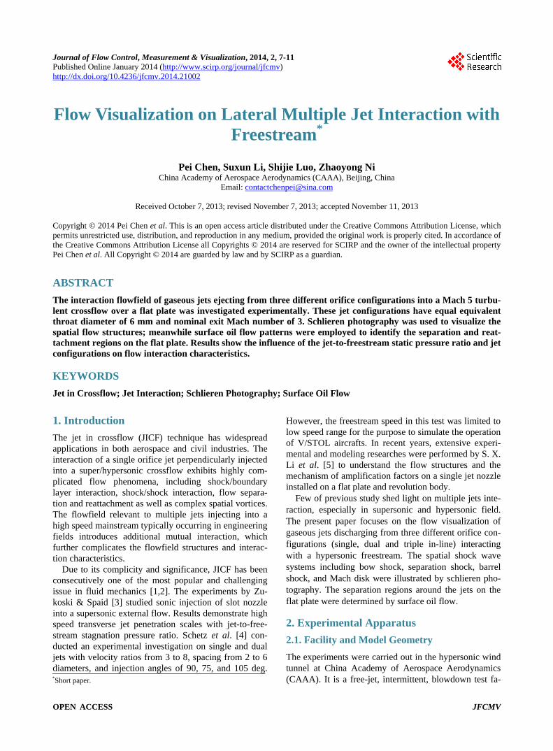
personic triple jets impinging with a hypersonic cross- flow appear in Figure 4, which was obtained from the author’s RANS numerical simulation with in-house CFD codes. As shown in this figure, the issuing jets expand rapidly and block the crossflow, then cause a three-di- mensional bow shock ahead of the first injection orifice. The bow shock produces an adverse pressure gradient and forces the approaching boundary layer to separate with an oblique separation shock. A large clockwise se- paration zone is developed between the bow shock and the separation shock, concurrent with a small counter- clockwise separation zone between the bow shock and the jet front. The expanded jets produce the barrel shock and Mach disk, then turn downwards and mix with the main stream. The static pressure on the flat plate begins to increase near the primary separation line, and then reaches a peak when the primary separation flow reat- taches the wall. In the wake of the jets, a low pressure rear separation region occurs. The whole interaction zone is enveloped by bow shock, separation shock in space and primary separation line on the flat plate. In this fig- ure, the spatial streamlines and streamwise vorticity on the cross plane illustrate the presence of horseshoe vortex, wake vortex and counter-rotating vortex.
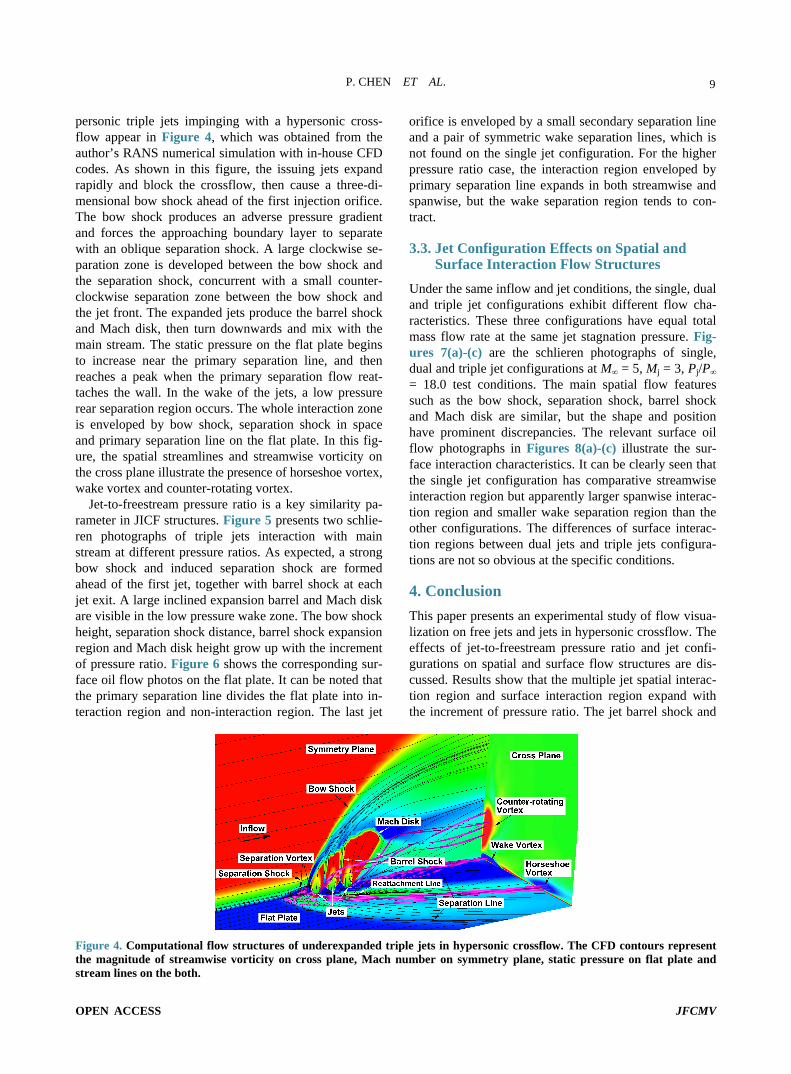
Jet-to-freestream pressure ratio is a key similarity pa- rameter in JICF structures. Figure 5 presents two schlie- ren photographs of triple jets interaction with main stream at different pressure ratios. As expected, a strong bow shock and induced separation shock are formed ahead of the first jet, together with barrel shock at each jet exit. A large inclined expansion barrel and Mach disk are visible in the low pressure wake zone. The bow shock height, separation shock distance, barrel shock expansion region and Mach disk height grow up with the increment of pressure ratio. Figure 6 shows the corresponding sur- face oil flow photos on the flat plate. It can be noted that the primary separation line divides the flat plate into in- teraction region and non-interaction region. The last jet
orifice is enveloped by a small secondary separation line and a pair of symmetric wake separation lines, which is not found on the single jet configuration. For the higher pressure ratio case, the interaction region enveloped by primary separation line expands in both streamwise and spanwise, but the wake separation region tends to con- tract.
3.3. Jet Configuration Effects on Spatial and Surface Interaction Flow Structures
Under the same inflow and jet conditions, the single, dual and triple jet configurations exhibit different flow cha- racteristics. These three configurations have equal total mass flow rate at the same jet stagnation pressure. Fig- ures 7(a)-(c) are the schlieren photographs of single, dual and triple jet configurations at M∞ = 5, Mj = 3, Pj/P∞ = 18.0 test conditions. The main spatial flow features such as the bow shock, separation shock, barrel shock and Mach disk are similar, but the shape and position have prominent discrepancies. The relevant surface oil flow photographs in Figures 8(a)-(c) illustrate the sur- face interaction characteristics. It can be clearly seen that the single jet configuration has comparative streamwise interaction region but apparently larger spanwise interac- tion region and smaller wake separation region than the other configurations. The differences of surface interac- tion regions between dual jets and triple jets configura- tions are not so obvious at the specific conditions.
4. Conclusion This paper presents an experimental study of flow visua- lization on free jets and jets in hypersonic crossflow. The effects of jet-to-freestream pressure ratio and jet confi- gurations on spatial and surface flow structures are dis- cussed. Results show that the multiple jet spatial interac- tion region and surface interaction region expand with the increment of pressure ratio. The jet barrel shock and
Figure 4. Computational flow structures of underexpanded triple jets in hypersonic crossflow. The CFD contours represent the magnitude of streamwise vorticity on cross plane, Mach number on symmetry plane, static pressure on flat plate and stream lines on the both.
P. CHEN ET AL.
OPEN ACCESS JFCMV
10
(a) (b)
Figure 5. Schlieren photos of triple jets at different pressure ratios (M∞ = 5, Mj = 3). (a) Pj/P∞ = 6.6; (b) Pj/P∞ = 23.4.
(a) (b)
Figure 6. Surface oil flow photos of triple jets at different pressure ratios (M∞ = 5, Mj = 3). (a) Pj/P∞ = 6.6; (b) Pj/P∞ = 23.4.
(a) (b) (c)
Figure 7. Schlieren photos of three jet configurations at a uniform pressure ratio (M∞ = 5, Mj = 3, Pj/P∞ = 18.0). (a) Single jet; (b) Dual jets; (c) Triple jets.
(a) (b) (c)
Figure 8. Surface oil flow photos of three jet configurations at a uniform pressure ratio (M∞ = 5, Mj = 3, Pj/P∞ = 18.0). (a) Single jet; (b) Dual jets; (c) Triple jets.
P. CHEN ET AL.
OPEN ACCESS JFCMV
11
Mach disk are influenced by the interaction between ad- jacent jets. Secondary separation line is clearly found around the last jet exit of multiple in-line jets. Under the same mass flow rate ratio, single jet configuration has larger interaction region and smaller wake region than multiple jet configurations.
REFERENCES [1] R. J. Margason, “Fifty Years of Jet in Cross Flow Re-
search,” AGARD Conference Proceedings, Winchester, 19- 22 April 1993, pp. 1-141.
[2] K. Mahesh, “The Interaction of Jets with Crossflow,” Annual Review of Fluid Mechanics, Vol. 45, 2013, pp. 379-407.
101115
http://dx.doi.org/10.1146/annurev-fluid-120710-
[3] F. W. Spaid and E. E. Zukoski, “A Study of the Injection of Gases from Transverse Slots with Supersonic External Flows,” AIAA Journal, Vol. 6, No. 2, 1968, pp. 205-212.
http://dx.doi.org/10.2514/3.4479 [4] J. A. Schetz, A. K. Jakubowskit and K. Aoyagi, “Surface
Pressures on a Flat Plate with Dual Jet Configurations,” Journal of Aircraft, Vol. 21, No.7, 1984, pp. 484-490. http://dx.doi.org/10.2514/3.44997
[5] S. X. Li, “Complex Flow Dominated by Shock Wave and Boundary Layer,” Science Press, Beijing, 2007. (in Chi- nese)


![] yE® à)h« û¬ g#r þ æH©ô~}(âà¦[Ø ÁÄ>#ôÈ` ³ C~ @· ) …€¦ · Replacement of the Sapphire Orifice Disk 174 Removing the Jet Assembly 176 Replacing the Jet Assembly](https://img.pdfslide.net/doc/110x75/5b8b678609d3f222638b5d1c/-ye-ah-u-gr-b-aehoaao-aaeoe-c-replacement.jpg)