Embed Size (px)
Citation preview

INSTALLATION &
OPERATION MANUAL
Redefine your comfort zone. ™ | www.titus-hvac.com
FlowBar Architectural
Linear DiffusersFL-10 / FL-15 / FL-20
FL-25 / FL-30

2 Installation Manual-FLOWBAR Redefine your comfort zone. ™ | www.titus-hvac.com
IOMFL-10/FL-15/FL-20/FL-25/FL-30
FlowBar Installed During Hard Ceiling Installation
SUMMARY OF STEPS TO INSTALL FLOWBAR WITH A HARD CEILING
Titus FlowBar Linear Diffusers are designed to integrate with the
ceiling system. The integration process takes place by installing
the diffuser concurrently with the ceiling. Figure 1 below summarizes the
STEP 1. Identify the Diffuser Border Type
STEP 2. Construct Ceiling Frame Work
STEP 3. Attach Mounting Clips to Diffuser
STEP 4. Attach Diffuser to Ceiling Frame Work
STEP 5. Attach Plenum to Diffuser
STEP 6. Attach Inlet Damper (if required)
STEP 7. Install Drywall
STEP 8. Review Installation
STEP 9. Finish the Surface
steps required to install a FlowBar Diffuser System as part of the hard
ceiling installation.
FRAME
MOUNTING
SCREWS
HARD CEILING CLIP
CENTERS
SPLINE SUPPORT CLIP
SS1
10" MAXIMUM
HI, H2, H3 or H4
FRAME
FRAME OPENIN
IN TABLE 1
WIDTH (W) SHOWN
Figure 1. Installation of FlowBar with a Hard Ceiling
3Installation Manual-FLOWBARRedefine your comfort zone. ™ | www.titus-hvac.com
FlowBar Installed During Hard Ceiling Installation (continued)
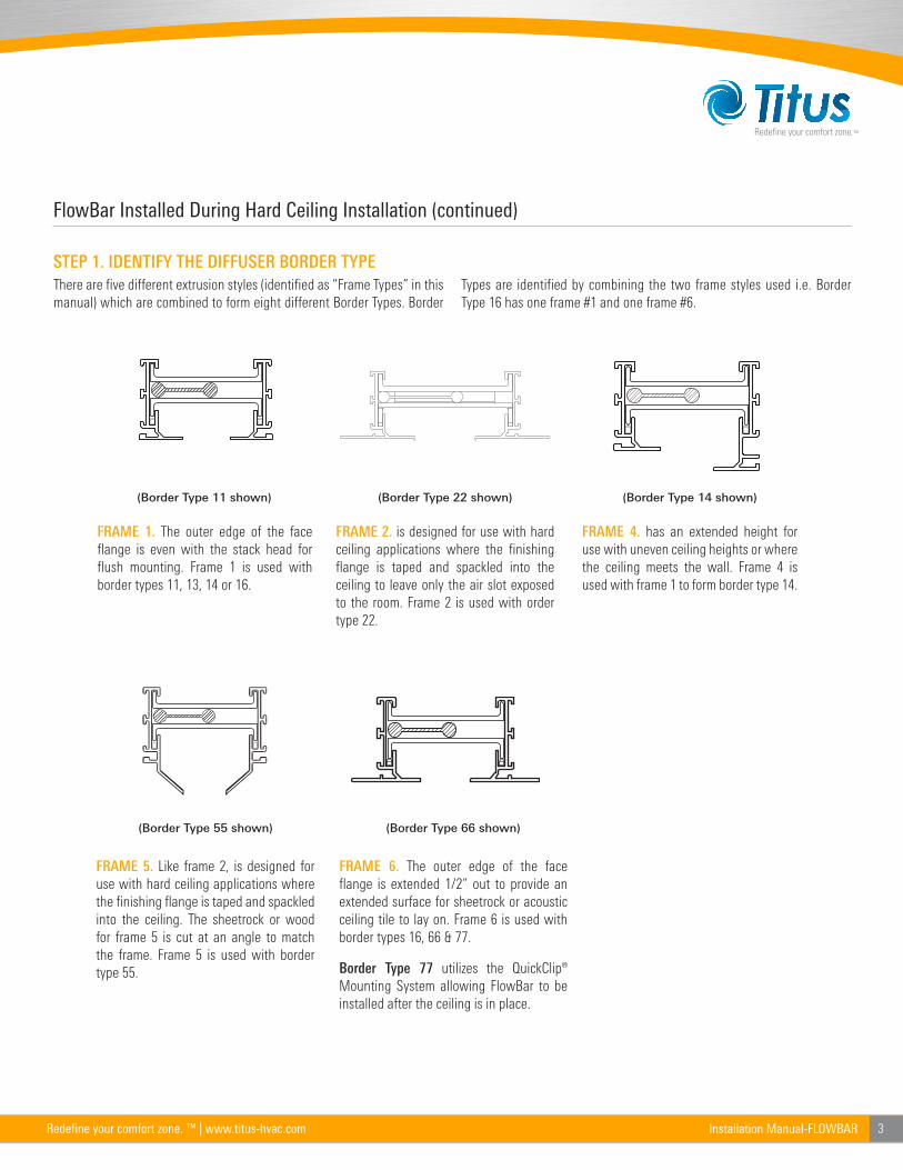
STEP 1. IDENTIFY THE DIFFUSER BORDER TYPE
There are five different extrusion styles (identified as “Frame Types” in this
manual) which are combined to form eight different Border Types. Border
Types are identified by combining the two frame styles used i.e. Border
Type 16 has one frame #1 and one frame #6.
FRAME 1. The outer edge of the face
flange is even with the stack head for
flush mounting. Frame 1 is used with
border types 11, 13, 14 or 16.
FRAME 2. is designed for use with hard
ceiling applications where the finishing
flange is taped and spackled into the
ceiling to leave only the air slot exposed
to the room. Frame 2 is used with order
type 22.
FRAME 4. has an extended height for
use with uneven ceiling heights or where
the ceiling meets the wall. Frame 4 is
used with frame 1 to form border type 14.
FRAME 5. Like frame 2, is designed for
use with hard ceiling applications where
the finishing flange is taped and spackled
into the ceiling. The sheetrock or wood
for frame 5 is cut at an angle to match
the frame. Frame 5 is used with border
type 55.
FRAME 6. The outer edge of the face
flange is extended 1/2” out to provide an
extended surface for sheetrock or acoustic
ceiling tile to lay on. Frame 6 is used with
border types 16, 66 & 77.
Border Type 77 utilizes the QuickClip®
Mounting System allowing FlowBar to be
installed after the ceiling is in place.
(Border Type 11 shown) (Border Type 14 shown)(Border Type 22 shown)
(Border Type 55 shown) (Border Type 66 shown)
4 Installation Manual-FLOWBAR Redefine your comfort zone. ™ | www.titus-hvac.com
IOMFL-10/FL-15/FL-20/FL-25/FL-30
FlowBar Installed During Hard Ceiling Installation (continued)
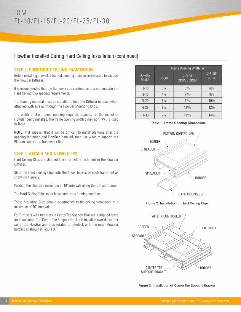
STEP 2. CONSTRUCT CEILING FRAMEWORK
Before installing drywall, a framed opening must be constructed to support
the FlowBar Diffuser.
It is recommended that the framework be continuous to accommodate the
Hard Ceiling Clip spacing requirements.
The framing material must be suitable to hold the Diffuser in place when
attached with screws through the FlowBar Mounting Clips.
The width of the framed opening required depends on the model of
FlowBar being installed. The frame opening width dimension, ‘W’, is listed
in Table 1.
NOTE: If it appears that it will be difficult to install plenums after the
opening is framed and FlowBar installed, then use wires to support the
Plenums above the framework first.
STEP 3. ATTACH MOUNTING CLIPS
Hard Ceiling Clips are shipped loose for field attachment to the FlowBar
Diffuser.
Slide the Hard Ceiling Clips into the lower bosses of each frame rail as
shown in Figure 2.
Position the clips at a maximum of 10” intervals along the Diffuser frame.
The Hard Ceiling Clips must be secured to a framing member.
These Mounting Clips should be attached to the ceiling framework at a
maximum of 10” intervals.
For Diffusers with two slots, a CenterTee Support Bracket is shipped loose
for installation. The Center-Tee Support Bracket is installed over the center
rail of the FlowBar and then rotated to interlock with the outer FlowBar
borders as shown in Figure 3.
FlowBar Model
Frame Opening Width (W)
1-SLOT2-SLOT
2CRA & 2CRB
2-SLOT 2CRN
FL-10 3¼ 511⁄16 69⁄16
FL-15 4¼ 711⁄16 89⁄16
FL-20 5¼ 911⁄16 109⁄16
FL-25 6¼ 1111⁄16 129⁄16
FL-30 7¼ 1311⁄16 149⁄16
Table 1. Frame Opening Dimensions
BORDER
SPREADER
PATTERN CONTROLLER
BORDERCENTER-TEE SUPPORT BRACKET
Figure 3. Installation of Center-Tee Support Bracket
Figure 2. Installation of Hard Ceiling Clips
PATTERN CONTROLLER
SPREADER
BORDER
SPREADER
HARD CEILING CLIP
BORDER
BORDER
SPREADER
SPREADER
BORDER
HARD CEILING CLIP
PATTERN CONTROLLER
CENTER-TEE
5Installation Manual-FLOWBARRedefine your comfort zone. ™ | www.titus-hvac.com
FlowBar Installed During Hard Ceiling Installation (continued)
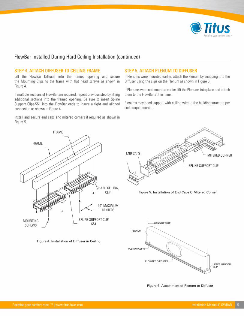
STEP 4. ATTACH DIFFUSER TO CEILING FRAME
Lift the FlowBar Diffuser into the framed opening and secure
the Mounting Clips to the frame with flat head screws as shown in
Figure 4.
If multiple sections of FlowBar are required, repeat previous step by lifting
additional sections into the framed opening. Be sure to insert Spline
Support Clips-SS1 into the FlowBar ends to insure a tight and aligned
connection as shown in Figure 4.
Install and secure end caps and mitered corners if required as shown in
Figure 5.
STEP 5. ATTACH PLENUM TO DIFFUSER
If Plenums were mounted earlier, attach the Plenum by snapping it to the
Diffuser using the clips on the Plenum as shown in Figure 6.
If Plenums were not mounted earlier, lift the Plenums into place and attach
them to the FlowBar at this time.
Plenums may need support with ceiling wire to the building structure per
code requirements.
END CAPS
SPLINE SUPPORT CLIP
MITERED CORNER
Figure 5. Installation of End Caps & Mitered Corner
PLENUM CLIPS
FLOWTEE DIFFUSER
PLENUM
UPPER HANGERCLIP
HANGAR WIRE
Figure 6. Attachment of Plenum to Diffuser
FRAME
FRAME
HARD CEILING CLIP
10” MAXIMUM CENTERS
SPLINE SUPPORT CLIP SS1
MOUNTING SCREWS
Figure 4. Installation of Diffuser in Ceiling
6 Installation Manual-FLOWBAR Redefine your comfort zone. ™ | www.titus-hvac.com
IOMFL-10/FL-15/FL-20/FL-25/FL-30
FlowBar Installed During Hard Ceiling Installation (continued)
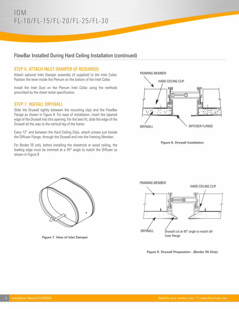
STEP 6. ATTACH INLET DAMPER (IF REQUIRED)
Attach optional Inlet Damper assembly (if supplied) to the Inlet Collar.
Position the lever inside the Plenum on the bottom of the Inlet Collar.
Install the Inlet Duct on the Plenum Inlet Collar using the methods
prescribed by the sheet metal specification.
STEP 7. INSTALL DRYWALL
Slide the Drywall tightly between the mounting clips and the FlowBar
Flange as shown in Figure 8. For ease of installation, insert the tapered
edge of the Drywall into this opening. For the best fit, slide the edge of the
Drywall all the way to the vertical leg of the frame.
Every 12” and between the Hard Ceiling Clips, attach screws just beside
the Diffuser Flange, through the Drywall and into the Framing Member.
For Border 55 only, before installing the sheetrock or wood ceiling, the
leading edge must be trimmed at a 45° angle to match the Diffuser as
shown in Figure 9.
DRYWALL DIFFUSER FLANGE
FRAMING MEMBER
HARD CEILING CLIP
HARD CEILING CLIP
DRYWALL
FRAMING MEMBER
Drywall cut at 45° angle to match dif-fuser flange
Figure 7. View of Inlet Damper
Figure 8. Drywall Installation
Figure 9. Drywall Preparation - (Border 55 Only)
7Installation Manual-FLOWBARRedefine your comfort zone. ™ | www.titus-hvac.com
FlowBar Installed During Hard Ceiling Installation (continued)
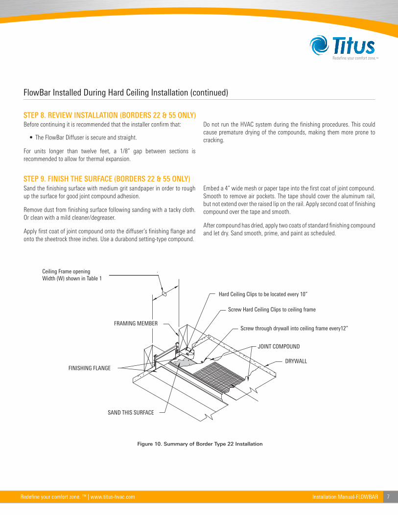
STEP 8. REVIEW INSTALLATION (BORDERS 22 & 55 ONLY)
STEP 9. FINISH THE SURFACE (BORDERS 22 & 55 ONLY)
Before continuing it is recommended that the installer confirm that:
• The FlowBar Diffuser is secure and straight.
For units longer than twelve feet, a 1/8” gap between sections is
recommended to allow for thermal expansion.
Sand the finishing surface with medium grit sandpaper in order to rough
up the surface for good joint compound adhesion.
Remove dust from finishing surface following sanding with a tacky cloth.
Or clean with a mild cleaner/degreaser.
Apply first coat of joint compound onto the diffuser’s finishing flange and
onto the sheetrock three inches. Use a durabond setting-type compound.
Do not run the HVAC system during the finishing procedures. This could
cause premature drying of the compounds, making them more prone to
cracking.
Embed a 4” wide mesh or paper tape into the first coat of joint compound.
Smooth to remove air pockets. The tape should cover the aluminum rail,
but not extend over the raised lip on the rail. Apply second coat of finishing
compound over the tape and smooth.
After compound has dried, apply two coats of standard finishing compound
and let dry. Sand smooth, prime, and paint as scheduled.
Framing Member
Finishing Flange
Joint Compound
4" wide mesh tape
Bonding Agent
Screw through drywall intoceiling frame every 12"
Hard Ceiling Clips to be located every 10"
Screw Hard Ceiling Clips to ceiling frame
Drywall
Hard Ceiling Clips to be located every 10”
Screw Hard Ceiling Clips to ceiling frame
Screw through drywall into ceiling frame every12”
JOINT COMPOUND
DRYWALL
SAND THIS SURFACE
FINISHING FLANGE
FRAMING MEMBER
Ceiling Frame opening Width (W) shown in Table 1
Figure 10. Summary of Border Type 22 Installation
8 Installation Manual-FLOWBAR Redefine your comfort zone. ™ | www.titus-hvac.com
IOMFL-10/FL-15/FL-20/FL-25/FL-30
FlowBar Installed After Hard Ceiling Installation
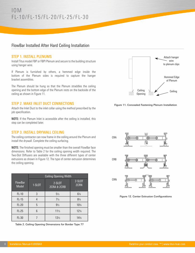
STEP 1. INSTALL PLENUMS
Install Titus model FBP or FBPI Plenum and secure to the building structure
using hanger wire.
If Plenum is furnished by others, a hemmed edge inside the
bottom of the Plenum sides is required to capture the hanger
bracket assemblies.
The Plenum should be hung so that the Plenum straddles the ceiling
opening and the bottom edge of the Plenum rests on the backside of the
ceiling as shown in Figure 11.
STEP 2. MAKE INLET DUCT CONNECTIONS
Attach the Inlet Duct to the inlet collar using the method prescribed by the
job specification.
NOTE: If the Plenum Inlet is accessible after the ceiling is installed, this
step can be completed later.
STEP 3. INSTALL DRYWALL CEILING
The ceiling contractor can now frame in the ceiling around the Plenum and
install the drywall. Complete the ceiling surfacing.
NOTE: The finished opening must be smaller than the overall FlowBar face
dimensions. Refer to Table 2 for the ceiling opening width required. The
Two-Slot Diffusers are available with the three different types of center
extrusions as shown in Figure 12. The type of center extrusion determines
the ceiling opening.
FlowBar Model
Ceiling Opening Width
1-SLOT2-SLOT
2CRA & 2CRB
2-SLOT 2CRN
FL-10 3 5½ 63⁄8
FL-15 4 7½ 83⁄8
FL-20 5 9½ 103⁄8
FL-25 6 11½ 123⁄8
FL-30 7 13½ 143⁄8
Table 2. Ceiling Opening Dimensions for Border Type 77
Attach hanger wire
to plenum clips
Hemmed Edge of Plenum
Ceiling Opening
Ceiling
CRA
CRB
CRN
Figure 11. Concealed Fastening Plenum Installation
Figure 12. Center Extrusion Conigurations
9Installation Manual-FLOWBARRedefine your comfort zone. ™ | www.titus-hvac.com
FlowBar Installed After Hard Ceiling Installation (continued)
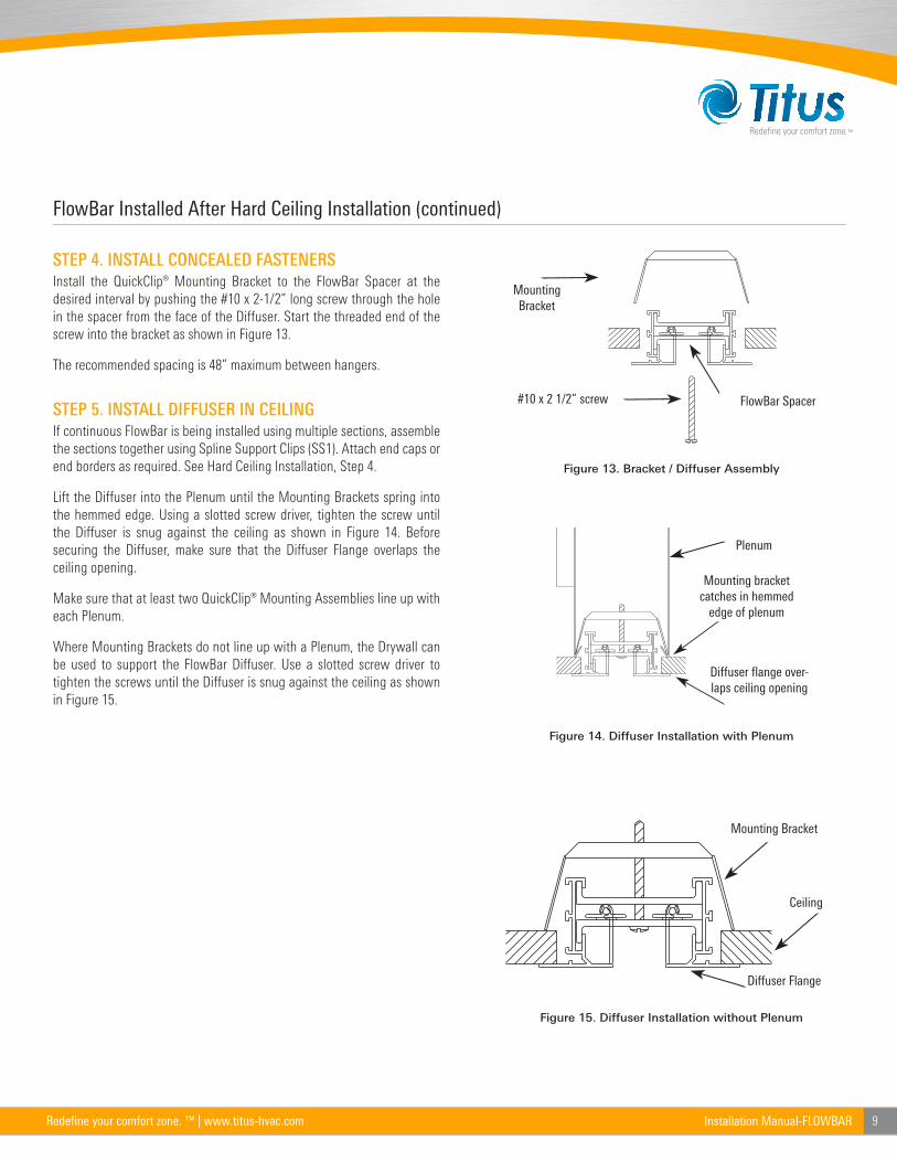
STEP 4. INSTALL CONCEALED FASTENERS
Install the QuickClip® Mounting Bracket to the FlowBar Spacer at the
desired interval by pushing the #10 x 2-1/2” long screw through the hole
in the spacer from the face of the Diffuser. Start the threaded end of the
screw into the bracket as shown in Figure 13.
The recommended spacing is 48” maximum between hangers.
STEP 5. INSTALL DIFFUSER IN CEILING
If continuous FlowBar is being installed using multiple sections, assemble
the sections together using Spline Support Clips (SS1). Attach end caps or
end borders as required. See Hard Ceiling Installation, Step 4.
Lift the Diffuser into the Plenum until the Mounting Brackets spring into
the hemmed edge. Using a slotted screw driver, tighten the screw until
the Diffuser is snug against the ceiling as shown in Figure 14. Before
securing the Diffuser, make sure that the Diffuser Flange overlaps the
ceiling opening.
Make sure that at least two QuickClip® Mounting Assemblies line up with
each Plenum.
Where Mounting Brackets do not line up with a Plenum, the Drywall can
be used to support the FlowBar Diffuser. Use a slotted screw driver to
tighten the screws until the Diffuser is snug against the ceiling as shown
in Figure 15.
Mounting Bracket
#10 x 2 1/2” screw FlowBar Spacer
Figure 13. Bracket / Diffuser Assembly
Plenum
Mounting bracket catches in hemmed
edge of plenum
Diffuser flange over-laps ceiling opening
Figure 14. Diffuser Installation with Plenum
Mounting Bracket
Ceiling
Diffuser Flange
Figure 15. Diffuser Installation without Plenum
10 Installation Manual-FLOWBAR Redefine your comfort zone. ™ | www.titus-hvac.com
IOMFL-10/FL-15/FL-20/FL-25/FL-30
Field Cutting Linear FlowBar
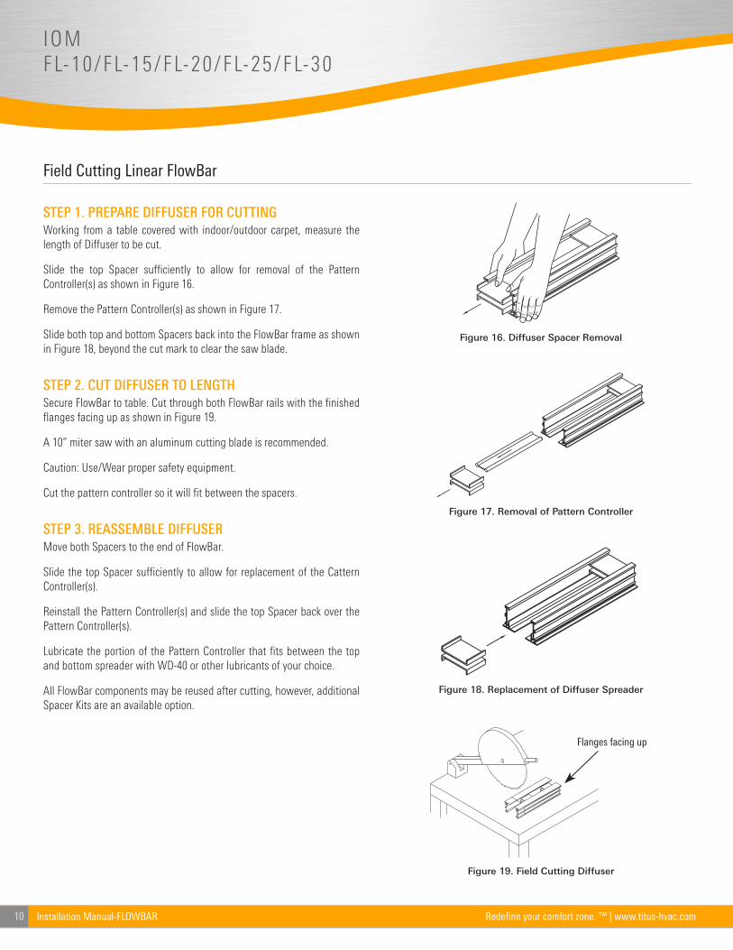
STEP 1. PREPARE DIFFUSER FOR CUTTING
Working from a table covered with indoor/outdoor carpet, measure the
length of Diffuser to be cut.
Slide the top Spacer sufficiently to allow for removal of the Pattern
Controller(s) as shown in Figure 16.
Remove the Pattern Controller(s) as shown in Figure 17.
Slide both top and bottom Spacers back into the FlowBar frame as shown
in Figure 18, beyond the cut mark to clear the saw blade.
STEP 2. CUT DIFFUSER TO LENGTH
Secure FlowBar to table. Cut through both FlowBar rails with the finished
flanges facing up as shown in Figure 19.
A 10” miter saw with an aluminum cutting blade is recommended.
Caution: Use/Wear proper safety equipment.
Cut the pattern controller so it will fit between the spacers.
STEP 3. REASSEMBLE DIFFUSER
Move both Spacers to the end of FlowBar.
Slide the top Spacer sufficiently to allow for replacement of the Cattern
Controller(s).
Reinstall the Pattern Controller(s) and slide the top Spacer back over the
Pattern Controller(s).
Lubricate the portion of the Pattern Controller that fits between the top
and bottom spreader with WD-40 or other lubricants of your choice.
All FlowBar components may be reused after cutting, however, additional
Spacer Kits are an available option.
Figure 16. Diffuser Spacer Removal
Figure 17. Removal of Pattern Controller
Figure 18. Replacement of Diffuser Spreader
Flanges facing up
Figure 19. Field Cutting Diffuser
11Installation Manual-FLOWBARRedefine your comfort zone. ™ | www.titus-hvac.com
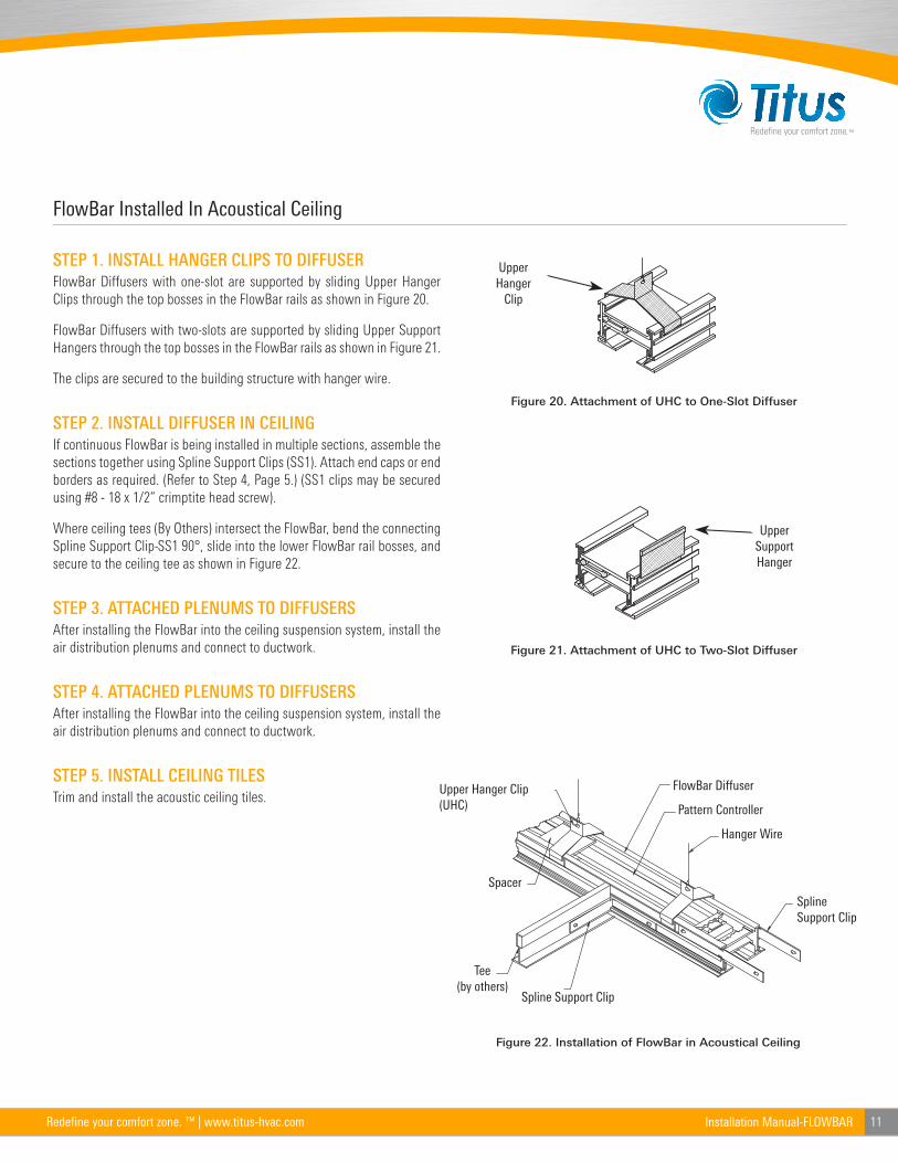
FlowBar Installed In Acoustical Ceiling
STEP 1. INSTALL HANGER CLIPS TO DIFFUSER
FlowBar Diffusers with one-slot are supported by sliding Upper Hanger
Clips through the top bosses in the FlowBar rails as shown in Figure 20.
FlowBar Diffusers with two-slots are supported by sliding Upper Support
Hangers through the top bosses in the FlowBar rails as shown in Figure 21.
The clips are secured to the building structure with hanger wire.
STEP 2. INSTALL DIFFUSER IN CEILING
If continuous FlowBar is being installed in multiple sections, assemble the
sections together using Spline Support Clips (SS1). Attach end caps or end
borders as required. (Refer to Step 4, Page 5.) (SS1 clips may be secured
using #8 - 18 x 1/2” crimptite head screw).
Where ceiling tees (By Others) intersect the FlowBar, bend the connecting
Spline Support Clip-SS1 90°, slide into the lower FlowBar rail bosses, and
secure to the ceiling tee as shown in Figure 22.
STEP 3. ATTACHED PLENUMS TO DIFFUSERS
After installing the FlowBar into the ceiling suspension system, install the
air distribution plenums and connect to ductwork.
STEP 4. ATTACHED PLENUMS TO DIFFUSERS
After installing the FlowBar into the ceiling suspension system, install the
air distribution plenums and connect to ductwork.
STEP 5. INSTALL CEILING TILES
Trim and install the acoustic ceiling tiles.
Upper Hanger
Clip
UpperSupport Hanger
Figure 20. Attachment of UHC to One-Slot Diffuser
Figure 21. Attachment of UHC to Two-Slot Diffuser
(by others)
Tee
SplineClip
ClipSpline
SpacerUnit
Hanger ClipUpper Diffuser
FlowBar
ControllerPattern
WireHanger
Upper Hanger Clip (UHC)
Spacer
Spline Support Clip
Spline Support Clip
Hanger Wire
Pattern Controller
FlowBar Diffuser
Tee(by others)
Figure 22. Installation of FlowBar in Acoustical Ceiling
12 Installation Manual-FLOWBAR Redefine your comfort zone. ™ | www.titus-hvac.com
IOMFL-10/FL-15/FL-20/FL-25/FL-30
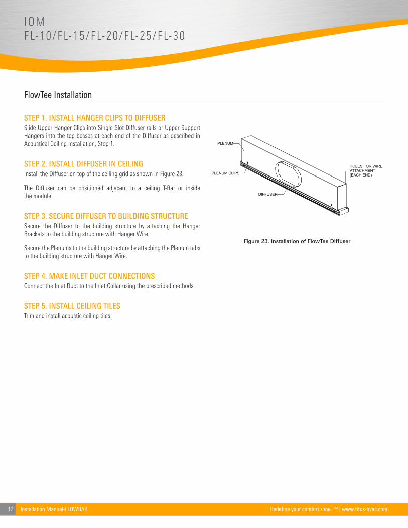
FlowTee Installation
STEP 1. INSTALL HANGER CLIPS TO DIFFUSER
Slide Upper Hanger Clips into Single Slot Diffuser rails or Upper Support
Hangers into the top bosses at each end of the Diffuser as described in
Acoustical Ceiling Installation, Step 1.
STEP 2. INSTALL DIFFUSER IN CEILING
Install the Diffuser on top of the ceiling grid as shown in Figure 23.
The Diffuser can be positioned adjacent to a ceiling T-Bar or inside
the module.
STEP 3. SECURE DIFFUSER TO BUILDING STRUCTURE
Secure the Diffuser to the building structure by attaching the Hanger
Brackets to the building structure with Hanger Wire.
Secure the Plenums to the building structure by attaching the Plenum tabs
to the building structure with Hanger Wire.
STEP 4. MAKE INLET DUCT CONNECTIONS
Connect the Inlet Duct to the Inlet Collar using the prescribed methods
STEP 5. INSTALL CEILING TILES
Trim and install acoustic ceiling tiles.
PLENUM CLIPS
DIFFUSER
PLENUM
HOLES FOR WIREATTACHMENT (EACH END)
Figure 23. Installation of FlowTee Diffuser
13Installation Manual-FLOWBARRedefine your comfort zone. ™ | www.titus-hvac.com
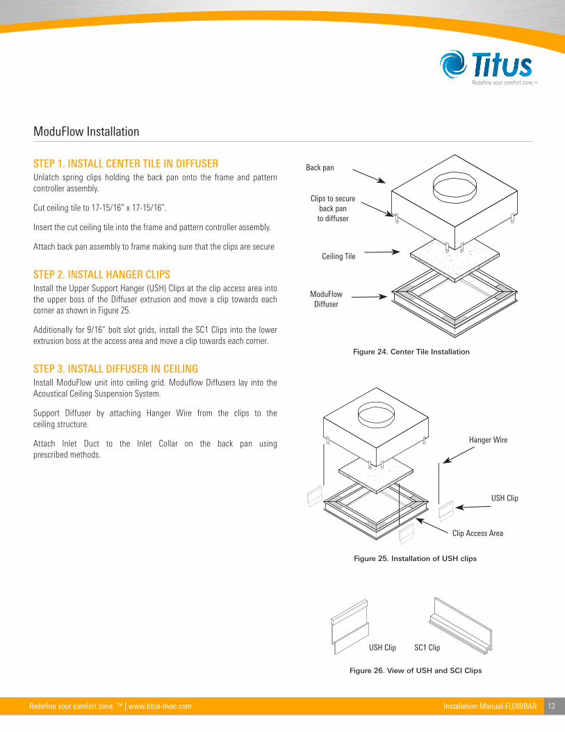
ModuFlow Installation
STEP 1. INSTALL CENTER TILE IN DIFFUSER
Unlatch spring clips holding the back pan onto the frame and pattern
controller assembly.
Cut ceiling tile to 17-15/16” x 17-15/16”.
Insert the cut ceiling tile into the frame and pattern controller assembly.
Attach back pan assembly to frame making sure that the clips are secure
STEP 2. INSTALL HANGER CLIPS
Install the Upper Support Hanger (USH) Clips at the clip access area into
the upper boss of the Diffuser extrusion and move a clip towards each
corner as shown in Figure 25.
Additionally for 9/16” bolt slot grids, install the SC1 Clips into the lower
extrusion boss at the access area and move a clip towards each corner.
STEP 3. INSTALL DIFFUSER IN CEILING
Install ModuFlow unit into ceiling grid. Moduflow Diffusers lay into the
Acoustical Ceiling Suspension System.
Support Diffuser by attaching Hanger Wire from the clips to the
ceiling structure.
Attach Inlet Duct to the Inlet Collar on the back pan using
prescribed methods.
Back pan
Clips to secureback pan to diffuser
Ceiling Tile
ModuFlowDiffuser
Figure 24. Center Tile Installation
USH Clip SC1 Clip
Hanger Wire
USH Clip
Clip Access Area
Figure 25. Installation of USH clips
Figure 26. View of USH and SCI Clips
14 Installation Manual-FLOWBAR Redefine your comfort zone. ™ | www.titus-hvac.com
IOMFL-10/FL-15/FL-20/FL-25/FL-30
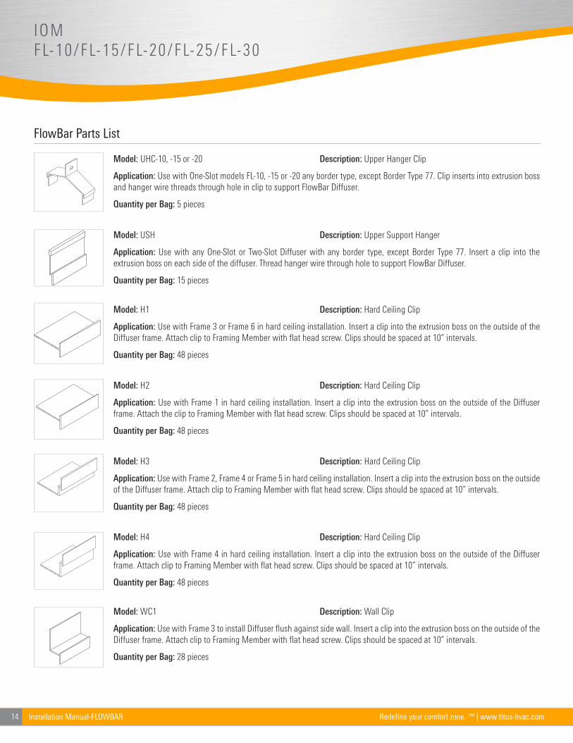
FlowBar Parts List
(797)
Model: UHC-10, -15 or -20 Description: Upper Hanger Clip
Application: Use with One-Slot models FL-10, -15 or -20 any border type, except Border Type 77. Clip inserts into extrusion boss
and hanger wire threads through hole in clip to support FlowBar Diffuser.
Quantity per Bag: 5 pieces
Model: USH Description: Upper Support Hanger
Application: Use with any One-Slot or Two-Slot Diffuser with any border type, except Border Type 77. Insert a clip into the
extrusion boss on each side of the diffuser. Thread hanger wire through hole to support FlowBar Diffuser.
Quantity per Bag: 15 pieces
Model: H1 Description: Hard Ceiling Clip
Application: Use with Frame 3 or Frame 6 in hard ceiling installation. Insert a clip into the extrusion boss on the outside of the
Diffuser frame. Attach clip to Framing Member with flat head screw. Clips should be spaced at 10” intervals.
Quantity per Bag: 48 pieces
Model: H2 Description: Hard Ceiling Clip
Application: Use with Frame 1 in hard ceiling installation. Insert a clip into the extrusion boss on the outside of the Diffuser
frame. Attach the clip to Framing Member with flat head screw. Clips should be spaced at 10” intervals.
Quantity per Bag: 48 pieces
Model: H3 Description: Hard Ceiling Clip
Application: Use with Frame 2, Frame 4 or Frame 5 in hard ceiling installation. Insert a clip into the extrusion boss on the outside
of the Diffuser frame. Attach clip to Framing Member with flat head screw. Clips should be spaced at 10” intervals.
Quantity per Bag: 48 pieces
Model: H4 Description: Hard Ceiling Clip
Application: Use with Frame 4 in hard ceiling installation. Insert a clip into the extrusion boss on the outside of the Diffuser
frame. Attach clip to Framing Member with flat head screw. Clips should be spaced at 10” intervals.
Quantity per Bag: 48 pieces
Model: WC1 Description: Wall Clip
Application: Use with Frame 3 to install Diffuser flush against side wall. Insert a clip into the extrusion boss on the outside of the
Diffuser frame. Attach clip to Framing Member with flat head screw. Clips should be spaced at 10” intervals.
Quantity per Bag: 28 pieces

15Installation Manual-FLOWBARRedefine your comfort zone. ™ | www.titus-hvac.com
FlowBar Parts List (continued)
Model: WC3 Description: Wall Clip
Application: Use with Frame 1 install Diffuser flush against side wall. Insert a clip into the extrusion boss on the outside of the
Diffuser frame. Attach clip to Framing Member with flat head screw. Clips should be spaced at 10” intervals.
Quantity per Bag: 28 pieces
Model: WC4 Description: Wall Clip
Application: Use with Frame 6 or 7 install Diffuser flush against side wall. Insert a clip into the extrusion boss on the outside of
the Diffuser frame. Attach clip to Framing Member with flat head screw. Clips should be spaced at 10” intervals.
Quantity per Bag: 28 pieces
Model: SS1 Description: Spline Support Clip
Application: Used to connect multiple sections of FlowBar Diffusers. Insert clip half way into the extrusion boss on the outside
of the Diffuser frame, then slide exposed end of Spline Support Clip into connecting piece of FlowBar.
Quantity per Bag: 28 pieces
Model: SS1 Description: Spline Support Clip
Application: SS1 Can also be used to connect FlowBar Diffuser to Accoustical Ceiling T-bar. Bend straight clip 90°. Insert clip
half way into the extrusion boss on the outside of the Diffuser frame, then slide exposed end of Spline Support Clip into T-bar.
Quantity per Bag: 28 pieces
Model: SC1 Description: ModuFlow Support Clip
Application: Use with ModuFlow Border Type 13 to install in Bolt-Slot Ceiling System. Insert a clip into the extrusion boss on the
outside of the Diffuser Frame 1. Thread Hanger Wire through hole in clip. Bottom of support clip rests on bolt slot ceiling bar.
Quantity per Bag: 28 pieces
Model: CFB-10, -15, -20, -25, -30 Description: Concealed Fastener Bracket Kit
Application: Use with FlowBar Border Type 77 to install FlowBar Diffuser after hard ceiling installation. Place Mounting Bracket
above Diffuser. Drill hole into existing FlowBar Spacer(s). Thread #10 x 2 1/2 flat head screw through each Spacer and into
Mounting Bracket. Tighten screw(s) until Diffuser Flanges draw tight against ceiling. Note: One-Slot models use one screw.
Two-Slot models use two screws.
Quantity per Bag: 4 pieces (includes four #10 x 2 1/2 screws for One-Slot models)
8 pieces (includes eight #10 x 2 1/2 screws for One-Slot models)
Model: WC2 Description: Wall Clip
Application: Use with Frame 1, Frame 3 or Frame 6 to install Diffuser with reveal against side wall. Insert a clip into the extrusion boss
on the outside of the Diffuser frame. Attach clip to Framing Member with flat head screw. Clips should be spaced at 10” intervals.
Quantity per Bag: 28 pieces

605 Shiloh RdPlano TX 75074ofc: 972.212.4800fax: 972.212.4884
Redefine your comfort zone. ™ | www.titus-hvac.com