Embed Size (px)
Citation preview

825B120AFLOWMETER MODBUS S/WPC modbus communication software
Minimum H/W requirements
FLOWMETER modbus program needs a PC with, atleast, Pentium processor or equivalent.
VGA 256 colours adapter
10 Mbytes hard disk free space
n.1 mouse
n.1 serial COM or USB port free to connect theRS485 transceiver
MS Windows 2000/XP.
applied solution for the application
fig.1
DESCRIPTION
“FLOWMETER MODBUS”Software communicates viastandard RS485 busconnection withFLOWMETER ultrasonicunits.When “FLOWMETERMODBUS” software starts, awindow is displayed on thescreen as shown in fig.2.
fig.2

Pag. 2 of 10
fig.3
HOW TO INSTALL
MAIN PAGE
To install the MODBUS software:
1) insert the install CD ROM
2) confirm the agreement license
3) Next to finish
4) restart the system
Now the program is ready to start (by the desktop’s icon)

Pag. 3 of 10
MAIN PAGECommunications software allows the user to display and setup the main Flowmeter operating parameters.The main panel (see fig. 3) shows the read-only system parameters:
Monitor- Flow, with relative flowrate (choice between l/s, l/min, l/h, m3/s, m3/min, m3/h)- Flow·%, referring to the maximum flow of the channel- Totalizer, liters or m3, depending on the flowrate- Distance [mm], measured by the transducer from the water surface- Head [mm], is used to calculate the flow rate (for the weirs the 0 head is not the bottom of the
channel, but the weir bottom, see fig.4)- Measure Status, system gain, expressed as a dimensionless number between 0 and 255- Slave address, FLOWMETER Modbus network address you want to monitor
Flow %- analog indicator of instantaneous flow (percentage)
Discharge curve- channel or flume programmed flow curve graph
Error Messages2 LEDs for errors in the transducer, with its explicit message:- Absence of echo received- Temperature outside the use range -30°C ÷ + 80°C- Measured flow exceeds the maximum flow- Gain exceeds the threshold, see the User Set Up (Max Gain TH)- Communication error on the serial line
Relays Status2 LEDs for relay status indication
fig.4

Pag. 4 of 10
USER SET UP
fig.4
From the main panel user can switch to the setup panel user (User Set Up, see fig.4) password-protected.This panel contains all the parameters for configuring the relays operation and some basic parameters for the properinstrument calibration.User must enter a password, “flowmeter”, to access this panel (see Fig. 5)
fig.5
Pag. 5 of 10
USER SET UP
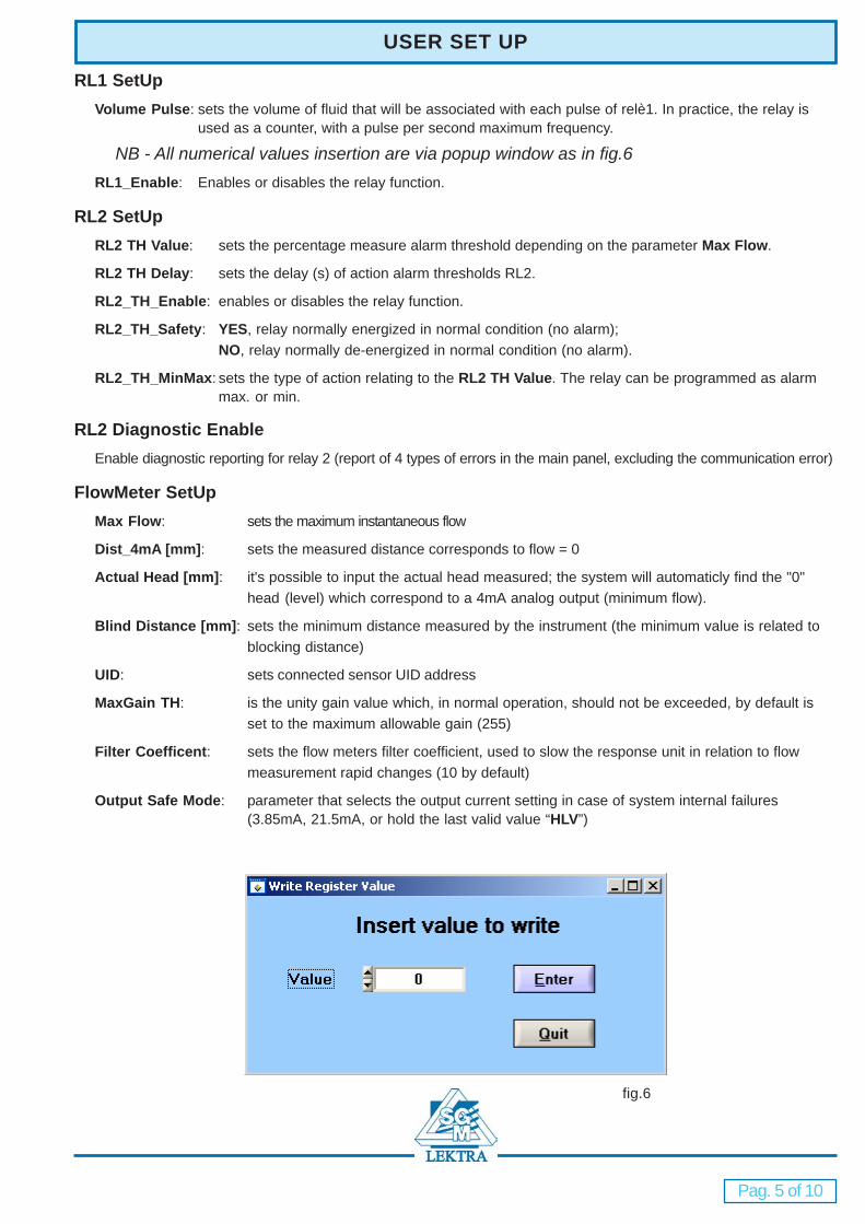
RL1 SetUpVolume Pulse: sets the volume of fluid that will be associated with each pulse of relè1. In practice, the relay is
used as a counter, with a pulse per second maximum frequency.
NB - All numerical values insertion are via popup window as in fig.6RL1_Enable: Enables or disables the relay function.
RL2 SetUpRL2 TH Value: sets the percentage measure alarm threshold depending on the parameter Max Flow.
RL2 TH Delay: sets the delay (s) of action alarm thresholds RL2.
RL2_TH_Enable: enables or disables the relay function.
RL2_TH_Safety: YES, relay normally energized in normal condition (no alarm);NO, relay normally de-energized in normal condition (no alarm).
RL2_TH_MinMax: sets the type of action relating to the RL2 TH Value. The relay can be programmed as alarmmax. or min.
RL2 Diagnostic EnableEnable diagnostic reporting for relay 2 (report of 4 types of errors in the main panel, excluding the communication error)
FlowMeter SetUpMax Flow: sets the maximum instantaneous flow
Dist_4mA [mm]: sets the measured distance corresponds to flow = 0
Actual Head [mm]: it's possible to input the actual head measured; the system will automaticly find the "0"head (level) which correspond to a 4mA analog output (minimum flow).
Blind Distance [mm]: sets the minimum distance measured by the instrument (the minimum value is related toblocking distance)
UID: sets connected sensor UID address
MaxGain TH: is the unity gain value which, in normal operation, should not be exceeded, by default isset to the maximum allowable gain (255)
Filter Coefficent: sets the flow meters filter coefficient, used to slow the response unit in relation to flowmeasurement rapid changes (10 by default)
Output Safe Mode: parameter that selects the output current setting in case of system internal failures(3.85mA, 21.5mA, or hold the last valid value “HLV”)
fig.6
Pag. 6 of 10
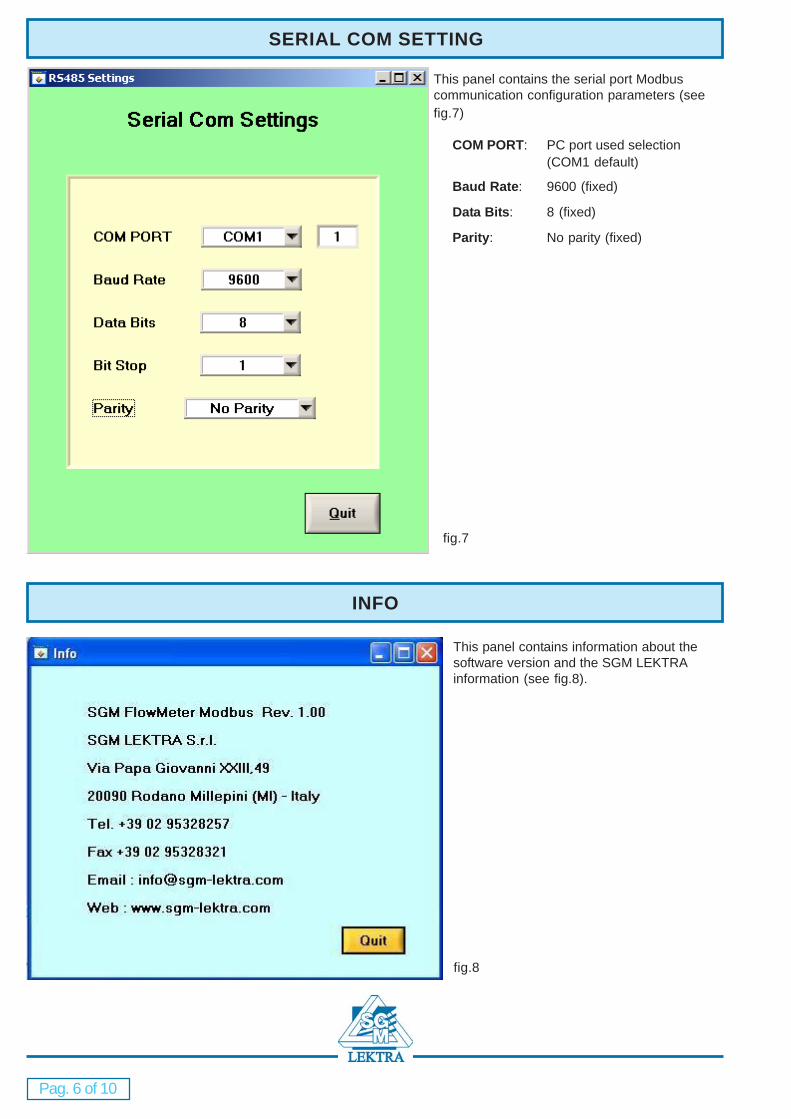
SERIAL COM SETTING
This panel contains the serial port Modbuscommunication configuration parameters (seefig.7)
COM PORT: PC port used selection(COM1 default)
Baud Rate: 9600 (fixed)
Data Bits: 8 (fixed)
Parity: No parity (fixed)
fig.7
INFO
This panel contains information about thesoftware version and the SGM LEKTRAinformation (see fig.8).
fig.8

Pag. 7 of 10
FLOW APPLICATION
In this panel, user can set the installed channel’s characteristics (Venturi flumes or channels), with model or “L”dimension insertion. User must enter a password, “flowmeter” to access this panel (see fig.5).
WeirsRect. suppressed weir “BAZIN”: select and place the "L" measure (see fig.9) shown in the
drawing "Weir / Flume Picture" (see fig.8)
fig.8
fig.9
Rect. contracted weir “FRANCIS”: select and write in the "L" measure (see fig.10) shownin the drawing "Weir / Flume Picture" (see fig. 8)
fig.10
Trapezoidal weir “CIPOLLETTI”: select and write in the "L" measure (see fig.11) shown inthe drawing "Weir / Flume Picture" (see fig. 8)
fig.11

Pag. 8 of 10
V-notch: select and write in the "E" angle (see fig.12) shown in the drawing"Weir / Flume Picture" (see fig. 8)
fig.12
FLOW APPLICATION
FlumesVenturi SGM-BS: select a standard SGM Venturi channel, or select “BS xxx”
and enter the custom SGM Venturi channel “L” measure(see fig. 13) fig.13
K-Venturi: select and write in the "L" measure (see fig.14) shown inthe drawing "Weir / Flume Picture" (see fig. 8) fig.14
Parshall: select the correct Parshall "L" measure (see fig.15) shown inthe drawing "Weir / Flume Picture" (see fig. 8)
fig.15
Parametersa / b / d / k: For non-standard weirs or channels user can flag the "Custom Mode" (see fig.8) and, by
pushing the “Custom Mode” button, enter the 4 flow curve basic parameters (a, b, d, k)through the window of fig.16
fig.16

Pag. 9 of 10
FLOW APPLICATION
TableInsert Table: For non-standard weirs or channels user can flag the "Table" and “Insert Table” (see fig.8) and, by
pushing the “Insert Table” button, enter the head-flow pairs through the window of fig.17 (31 pairs max.)In this case the instantaneous flow is obtained by linear interpolation between the data entered.
fig.17

Pag. 10 of 10
DATALOGGER
In this panel (fig.18), user sets the file datalogging parameters: enter a file name (new or existing file), set thewriting time records (from 5 sec. to 30 min.), start or stop writing records.The file data contained are:
Date [gg.mm.aaaa]
Hour [hh.mm.ss]
Head [mm]
Instantaneous flow [related Flowrate]
Totalizer [related Flowrate]
Flowrate [l/s, l/min, l/h, m3/s, m3/min, m3/h]
Measure Status
Temperature [°C]
Relay 2 status [On/Off]
“File Size” indicates the existing file’s dimension
FLOW APPLICATION
fig.18

Pag. 11 of 10
FLOW APPLICATION

“FLOWMETER ” Factory test certificate
Products supplied by SGM LEKTRA are guaranteed for a period of 12 (twelve) months fromdelivery date according to the conditions specified in our sale conditions document. SGMLEKTRA can choose to repair or replace the Product. If the Product is repaired it will mantein theoriginal term of guarantee, whereas if the Product is replaced it will have 12 (twelve) months ofguarantee. The warranty will be null if the Client modifies, repair or uses the Products for otherpurposes than the normal conditions foreseen by instructions or Contract. In no circumstancesshall SGM LEKTRA be liable for direct, indirect or consequiential or other loss or damagewhether caused by negligence on the part of the company or its employees or otherwisehowsoever arising out of defective goods.
FLOWMETER - WARRANTY
In conformity to the company and check procedure I certify that the equipment:
FLOWMETER Serial n. ...................... Version n. ......................
is conform to the technical requirements and it is made in conformity to the SGM-LEKTRA proce-dure
Quality Control Manager
.............................................................................................
Production and check date
.............................................................................................
SGM LEKTRA s.r.l.
documentation subject to technical change with no prior warning
SGM LEKTRA s.r.l.Via Papa Giovanni XXIII, 4920090 Rodano (Milano)tel. ++39 0295328257 r.a.fax ++39 0295328321e-mail: [email protected]: www.sgm-lektra.com

![User's AXF Manual Magnetic Flowmeter Integral Flowmeter ... · User's Manual Yo kogawa Electric Corporation AXF Magnetic Flowmeter Integral Flowmeter/ Remote Flowtube [Hardware Edition]](https://img.pdfslide.net/doc/110x75/5c40f15893f3c338c3289cbb/users-axf-manual-magnetic-flowmeter-integral-flowmeter-users-manual-yo.jpg)


![User's AXF Manual Magnetic Flowmeter Integral Flowmeter ... · Magnetic Flowmeter Integral Flowmeter/ Remote Flowtube [Hardware Edition] IM 01E20D01-01E IM 01E20D01-01E 7th Edition](https://img.pdfslide.net/doc/110x75/5e9c29fa54300501b21ae83a/users-axf-manual-magnetic-flowmeter-integral-flowmeter-magnetic-flowmeter-integral.jpg)


![User´s AXFA14G/C Manual Magnetic Flowmeter Remote ... · AXFA14G/C Magnetic Flowmeter Remote Converter [Hardware Edition/Software Edition] AXF Magnetic Flowmeter Integral Flowmeter](https://img.pdfslide.net/doc/110x75/5e9c29ae5a06915e2b2224e0/users-axfa14gc-manual-magnetic-flowmeter-remote-axfa14gc-magnetic-flowmeter.jpg)

![n8b6s9r3.rocketcdn.me · SGM-3416/3416L Super High End Microphones SGM-3416 — — 4KHz — Professional Shotgun Microphones A AZDEN SGM-3416L E]AZDEN SGM-3416 SGM-IOOO](https://img.pdfslide.net/doc/110x75/5f6da2e876fbb12c2d6dad7f/sgm-34163416l-super-high-end-microphones-sgm-3416-a-a-4khz-a-professional.jpg)

![MODBUS IINDUSTRIE sWETTERSTATIONNDUSTRIE …€¦ · MODBUS rain[e]one Modbus INDUSTRY Modbus Pyranometer THP[pro] Modbus rain one Modbus IN Wiegender Nieder-schlagssensor Windrichtung](https://img.pdfslide.net/doc/110x75/5eb88fa576fba607cd617fd5/modbus-iindustrie-swetterstationndustrie-modbus-raineone-modbus-industry-modbus.jpg)

![AXR Two-wire Magnetic Flowmeter Integral Flowmeter [Style:S2]](https://img.pdfslide.net/doc/110x75/62cb14e07ee31d38b74d3e5b/axr-two-wire-magnetic-flowmeter-integral-flowmeter-styles2.jpg)