Embed Size (px)
Citation preview
FLOWSHEET DEVELOPMENT FOR THE EXTRACTION OF RARE EARTHS USING
MINTEK’S PYEARTH™ PROCESS
*K. Bisaka1, I. Thobadi
1, S. Mokoena
2, C. Pawlik
2, and M. Erwee
1
1Mintek Pyrometallurgy Division
2Mintek Hydrometallurgy Division
MINTEK
200 Malibongwe Drive, Randburg, Johannesburg, South Africa, 2194
(*Corresponding author: [email protected])
ABSTRACT
The PyEarth™ process developed at Mintek has been demonstrated successfully at pilot scale.
Nine tons of ore containing 2.3 mass % of total rare earth oxides (TREO) from a dormant mineralogically
complex iron-rich ore deposit, was subjected to a concentrating smelting step in a 200 kW DC open-arc
pilot furnace and the rare earths from the resulting slag were extracted via a hydrometallurgical route. This
ore deposit is practically not amenable to extraction by conventional methods. The testwork results proved
that the PyEarth™ process was able to optimize the extraction of rare earths while minimizing waste
through the removal of iron as a saleable iron alloy. Reduction of iron to the alloy in the smelting step was
found flexible, efficient, and controllable, while rare earths were left virtually unreduced in the slag phase.
The slag chemistry is selected to optimize both the smelting and leaching performances as well as the alloy
composition. Leaching of the resulting slag was found possible and most efficient in hydrochloric acid
amongst other lixiviants tested.
KEYWORDS
Direct smelting, Extraction, Hydrochloric leaching, Iron rich rare earth bearing ore, PyEarth, Rare earth
COM2017 | THE CONFERENCE OF METALLURGISTS hosting World Gold & Nickel Cobalt Proceedings ISBN: 978-1-926872-36-0
Published by the Canadian Institute of Mining, Metallurgy and Petroleum | www.metsoc.org

INTRODUCTION
Rare earth elements have been used extensively over the past decade in the manufacture of clean
technology items such as wind turbines, hybrid and electric car batteries, magnetic levitation (‗maglev‘)
trains and many more. High-strength magnets are among the major applications of rare earths. These
elements also find applications in catalysts, and in military equipment such as armoured vehicle navigation
systems, submarine engines, and missile guidance systems, and even for refining jet fuel (Gupta et al.,
2004).
Rare earths are found in natural deposits with varying abundance, mineralogy, and textures. The
proven global rare earth oxide (REO) reserves are estimated at about 110 million tons (Wang et al., 2015),
with about 43% of the global reserves located in China. Namibia has the second-largest reserves
worldwide, with 20 million tons. South Africa has reserves of 1 million tons. Other rare-earth resources are
located in Russia (17%), the United States of America (12%), Australia, India, Brazil, and Greenland
(Gupta & Krishnamurthy, 2004).
About 130 000 t/a of rare-earth oxide (REO) is produced globally, with about 90% of this
production coming from China. Notwithstanding the available large reserves worldwide, the bulk of global
production of rare earths comes from the Bayan Obo in China and the Mount Weld area in Australia (Long
et al., 2010; Li et al., 2014; Haque et al., 2014). These deposits are mainly ferruginous (iron-rich) rare
earth-bearing ores. The Bayan Obo (China) ore contains 6% REO and 35% Fe; it is dominantly composed
of discrete minerals of bastnaesite and monazite, with a minor proportion intimately intergrown within Fe
oxide minerals (dominantly hematite and magnetite). The principal REE minerals at Mount Weld
(Australia) include monazite, and, in parts, xenotime. The monazite would appear to be altered, secondary
in nature, closely associated with Fe oxides; its average ore grade is 15.4% REO (Haque et al., 2014).
More than 50% of current world production of rare earths is currently consumed in China.
Consumption of REO is projected to increase at a rate of 6–10% per annum and could reach a volume of
200 000 t/a in the very near future (Long et al., 2010; Li et al., 2014; Wang et al., 2015).
The ore from the southern African regions is dominated by Fe and Mn oxides and oxyhydroxides
such as goethite and manganomelane minerals, the latter sometimes containing Ba. These minerals account
for more than 65% of the ore, and contribute to a high Fe content. Rare earth element minerals are
monazite, chemically weathered or altered monazite, and REE-bearing Al phosphates of the crandallite
group (florencite, gorxceite, crandallite). Additionally, rhabdophane, Ce-pyrochlore, and Ca monazite
(cheralite) are sometimes observed. As such, altered monazite is often finer-grained than monazite, and
displays poorer liberation. Nevertheless, most of the REE minerals occur in size classes < 20–30 m, and
very fine intergrowths with the Fe-Mn oxyhydroxide minerals preclude liberation, even at very fine sizes
(Chetty et al., 2017).
BRIEF OVERVIEW OF RARE EARTH EXTRACTION
Conventional processes
Highly efficient separation technologies have been key to the exploitation of the rare earths. The
extraction of rare earths should be sustainable, environmentally friendly, and economically viable.
Conventional flowsheets used include milling, and production by physical methods of a concentrate, from
which rare earths are recovered by hydrometallurgical means.
The Bayan Obo ore is milled to 90–95% passing 74 m, and then processed through low- and
high-intensity magnetic separation, and flotation of iron minerals, leaving cleaner tailings concentrating
REE minerals. However, the REE are concentrated using flotation of milled ores for the Mount Weld
process (Li & Yang, 2014).
Flowsheets are particularly designed to meet mineralogical challenges. The cost of the
conventional extraction process increases with mineralogical complexity, as more process units would be
FeMnOx
COM2017 | THE CONFERENCE OF METALLURGISTS hosting World Gold & Nickel Cobalt Proceedings ISBN: 978-1-926872-36-0
Published by the Canadian Institute of Mining, Metallurgy and Petroleum | www.metsoc.org

required to extract the rare earths and also to minimise pollution of the environment and groundwater with
the radioactive wastes generated.
PyEarth process
Upgrading of ore from a number of deposits, particularly those from the southern African regions,
by physical methods would not be economically viable because of the complexity of the mineralogy. These
ores would require fine milling to liberate the rare earth oxide species, and concentration of very fine
milled materials is rather challenging. Application of fine milling below 35 m size is not usual in
commercial operations because this is energy-intensive and costly. Research activities are geared towards
development of more efficient flotation reagents that will enable the upgrading of the ore into a rich rare
earth concentrate. For all these reasons, upgrading the low-grade (typically 2.5% REO) ferruginised
southern African ores using the conventional process was found to be very challenging and inefficient. The
high Fe content (> 30% Fe), and textural and mineral complexity, precluded the typical processing route of
comminution, physical separation, and leaching.
A novel process, called PyEarth™, was invented by Mintek, and employs direct smelting of the
ores to selectively remove iron as a saleable Fe-rich alloy whilst concentrating the REO in the slag phase.
The direct smelting approach considered the general principles of the pyrometallurgical process: the
thermodynamics and furnace operation. The basic premise is to selectively reduce iron oxide (Fe2O3,
Fe3O4, FeO in FeO(OH)) to iron, thereby concentrating REOs in the slag, as most rare earth oxides are not
readily reduced to metallic form at lower smelting temperatures of between 1450 and 1550°C. In this
temperature range, the iron oxides are easily reduced by carbon, and the manganese oxides are moderately
easily reduced, whereas, for example, CeO2, La2O3, and Ce2O3 are (in increasing order) much harder to
reduce.
As ores in the southern parts of Africa are very rich in iron oxides, reductive smelting of such ores
could potentially result in significant upgrading of the REO content of the resultant slag.
A number of laboratory-scale smelting tests were conducted in alumina, magnesia, and graphite
crucibles. The crucible tests provided information that was useful for the pilot tests that are outlined here
(Bisaka et al., 2016).
- The rare earth-bearing slag is of amphoteric nature when considering the wear of alumina and
magnesia crucibles. This erosion was the cause of crucible failures and contamination of the final
slag product, thus affecting the REO grade of the slag.
- Clean separation between the slag and metal was only achieved at high temperatures, above
1700°C. The crucible products displayed poor separation at lower temperatures.
- Clean slag with the highest REE grade, up to 13% REE, was achieved in the graphite crucible.
- The recovery of Fe to the alloy was > 98%.
- Full recovery of rare earth to the slag was achieved.
- A graphite lining was recommended for the pilot-scale furnace.
The slag produced was submitted to various leaching tests. The leaching tests showed the
following (Bisaka et al., 2016):
- Alumina contamination affected the leaching efficiency.
- HCl leaching of the clean slag produced in the graphite crucible was the most efficient, with
leaching extraction as high as 98%.
The objective of the current work was to demonstrate the smelting of the iron-rich rare earth ore in
Mintek‘s 200 kW DC arc furnace, and the leaching of the slag produced from the pilot smelting tests.
COM2017 | THE CONFERENCE OF METALLURGISTS hosting World Gold & Nickel Cobalt Proceedings ISBN: 978-1-926872-36-0
Published by the Canadian Institute of Mining, Metallurgy and Petroleum | www.metsoc.org

Operating an iron-rich rare earth smelting process in a DC arc furnace requires a knowledge of the
products' properties, particularly the slag properties such as the slag liquidus temperature, viscosity, and
density. These parameters contribute significantly to the metal-slag separation, flowability, and the thermal
energy distribution in the furnace. As data for rare earth-bearing slags are scarce in the open literature,
theoretical simulations of the slag properties were carried out to estimate the performance of the slag in a
DC arc furnace.
SMELTING TESTWORK
Raw materials
Nine tons of iron-rich rare earth-bearing ore from a southern African deposit was subjected to the
smelting tests in Mintek‘s 200 kW DC arc furnace. The ore, with 100% passing -6 mm, was processed as
received without any further size reduction or physical preparation. A sub-sample of the ore was submitted
for chemical and mineralogical characterisation. The bulk chemical composition was determined by a
Varian Vista-PRO CCD simultaneous inductively coupled plasma optical emission spectrometer (ICP-
OES). The morphological and phase chemical compositions were determined by Zeiss MA15 scanning
electron microscopy (SEM) equipped with a Bruker energy-dispersive spectrometer (EDS) and Bruker D8
advanced X-ray diffractometer (XRD), respectively. The chemical composition of the ore is given in Table
1. The proximate analysis of the anthracite is given in Table 2. High-purity CaO was used as a fluxing
agent to improve the smelting process, particularly to decrease the slag liquidus temperature and
viscosity—constraints that are exacerbated at small scale. Few rare earth elements with concentrations
higher than 100ppm are included in Table 1. Concentrations of Th and U in the ore were 221 and 72 ppm,
respectively.
Table 1. Summary of the bulk chemical composition of the iron-rich rare-earth ore (mass %) MgO
%
Al2O3
%
SiO2
%
CaO
%
TiO2
%
MnO
%
FeO(OH)
%
P2O5
%
La
ppm
Ce
ppm
Nd
ppm
TREE
%
1.13 6.48 6.08 2.06 3.87 9.09 52.45 1.77 6,060 10,200 3,900 2.34
Table 2. Summary of the bulk chemical composition of the anthracite (mass %)
Ash Volatiles Fixed carbon Total sulphur
12.2 4.3 81.2 0.71
Pilot smelting setup
The 200 kW DC arc furnace facility used for this smelting work is schematically presented in
Figure 1. The furnace is made of a shell having an outer diameter of 1 m. The water-spray-cooled steel
shell is lined with a single layer of graphite bricks, three rows high, and a hearth lined with rammable
carbon-based materials. The refractory lining resulted in a furnace crucible internal diameter (ID) of
approximately 0.7 m. The furnace was equipped with an alumina-lined conical roof, and a shell bolted onto
a domed base. A single tap-hole was used to tap a stream of both molten slag and metal. A centrally-
located graphite electrode of 40 mm diameter operated as a cathode, and the anode was constituted of steel
pins buried in the hearth. The feed system comprised individual hoppers used to feed ore, anthracite, and
limestone. The furnace is equipped with an off-gas system for the cleaning of process gases prior to their
release to the atmosphere.
COM2017 | THE CONFERENCE OF METALLURGISTS hosting World Gold & Nickel Cobalt Proceedings ISBN: 978-1-926872-36-0
Published by the Canadian Institute of Mining, Metallurgy and Petroleum | www.metsoc.org

Figure 1. Schematic diagram of the 200 kW DC arc furnace pilot facility
Experimental description
Various conditions were investigated throughout the 92 batches that made up the smelting
testwork. Anthracite additions were gradually increased from 12.5% to 25%, and two conditions of
limestone addition at 1–5% were tested. As in the laboratory-scale tests conducted previously, lime was
added to improve the reduction of MnO, and to lower the viscosity of the slag. The discussions in this
paper will be focused around the furnace behaviour and the analyses of the products.
SMELTING RESULTS
Chemical analyses and recoveries
The pilot process consisted of current-control furnace operation with constant power and constant
feed rate. After a batch of about 120 kg of rare earth ore was fed into the furnace, the tap-hole was opened
to release the molten materials. The latter were collected into a ladle, and left to cool prior to separation
and sampling. The samples were sent for chemical analysis.
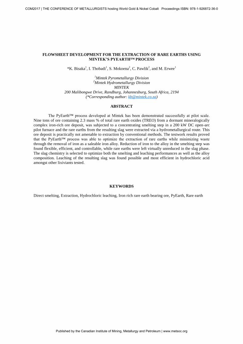
The molten material flowed freely when the tap-hole was opened. Clean metal and slag layers
were separated after solidification in a ladle. The good metal-slag separation confirmed that acceptable slag
properties were achieved. As can be seen in Figure 2, the FeO content in the slag decreased with increasing
anthracite addition, while the REE concentration in the slag increased. Figure 2 also shows that when 5%
limestone was added with 21.5% anthracite (in ratio to the ore), the concentration of REE increased to a
greater extent. REE were typically upgraded to more than 7 – 8%, and the highest REE was slightly above
10% in the present testwork; this is 4 times the REE concentration in the ore.
The evolution of the alloy analyses through the testwork is presented in Figure 3. The
concentration of Fe in the alloy decreased while Mn increased. At low reduction of Mn, Fe was in the
range of 96 to 98%. The highest Mn in the alloy was closer to 5%. Lower reduction of Mn was observed in
this testwork as compared to the crucible tests where the Mn in the alloy was more than 10% (Bisaka et al.,
2016). The low levels of MnO reduction in the pilot tests were attributed to the low operating temperatures
achieved in the pilot tests. The operating temperature of the furnace was 1600oC towards the last batches.
COM2017 | THE CONFERENCE OF METALLURGISTS hosting World Gold & Nickel Cobalt Proceedings ISBN: 978-1-926872-36-0
Published by the Canadian Institute of Mining, Metallurgy and Petroleum | www.metsoc.org
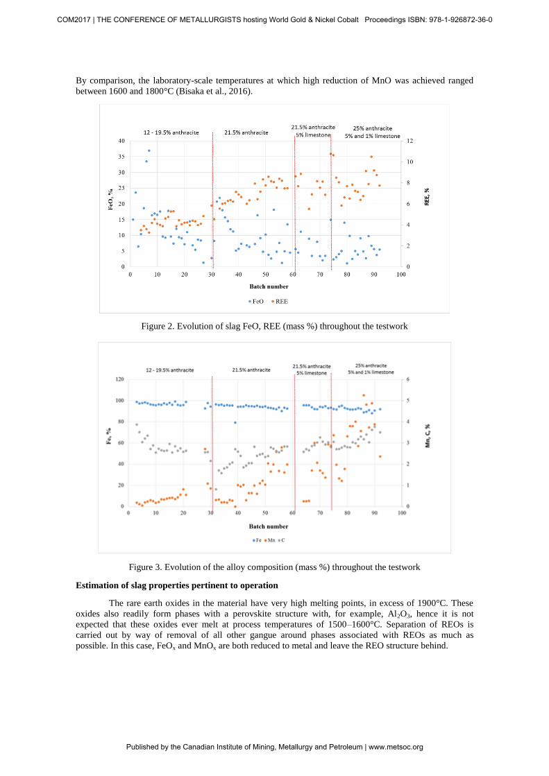
By comparison, the laboratory-scale temperatures at which high reduction of MnO was achieved ranged
between 1600 and 1800°C (Bisaka et al., 2016).
Figure 2. Evolution of slag FeO, REE (mass %) throughout the testwork
Figure 3. Evolution of the alloy composition (mass %) throughout the testwork
Estimation of slag properties pertinent to operation
The rare earth oxides in the material have very high melting points, in excess of 1900°C. These
oxides also readily form phases with a perovskite structure with, for example, Al2O3, hence it is not
expected that these oxides ever melt at process temperatures of 1500–1600°C. Separation of REOs is
carried out by way of removal of all other gangue around phases associated with REOs as much as
possible. In this case, FeOx and MnOx are both reduced to metal and leave the REO structure behind.
COM2017 | THE CONFERENCE OF METALLURGISTS hosting World Gold & Nickel Cobalt Proceedings ISBN: 978-1-926872-36-0
Published by the Canadian Institute of Mining, Metallurgy and Petroleum | www.metsoc.org

The slag formed in this process is relatively complex to study, based on the fact that it contains
many components for which limited information is available for the estimation of slag properties (in this
case liquidus and viscosity). Major components expected in the slag were 5–15% FeOx, 20% MnOx, 15–
20% Al2O3, 20–30% SiO2, 1–5% MgO, 5–20% CaO, 1–10% BaO, and 9–12% TiO2. Other components
include 2–3% SrO, as well as the rare earth oxides. The liquidus temperature of the slag was initially
estimated using FactSage 6.4, using all the components in the slag excluding SrO, BaO, and the REOs.
Data for BaO-solutions became available in FactSage 7.1, released in January 2017, and all of the
calculations were repeated using the new database.
The testwork was grouped into four broad categories:
No flux, with 12 – 19.5% anthracite, which yielded a slag with %FeO + %MnO ~ 35%
No flux, with 21.5% anthracite, which yielded a slag with %FeO + %MnO ~ 30%
Additions of 21.5% anthracite and 5% limestone
Additions of 25% anthracite and between 1 and 5% limestone.
For the bulk (>85%) of the slag consisting of FeO, MnO, Al2O3, SiO2, MgO, TiO2, and BaO, the
liquidus temperature was estimated for the different conditions tested. It was found that the liquidus
temperature of the bulk slag (excluding SrO and rare earth oxides), under reducing conditions, was
between 1400 and 1450°C for slags where the %FeO + %MnO was between 30 and 35%, while for slags
with very little (< 5% FeO, and/or < 5% MnO), the liquidus temperature was slightly higher at 1520–
1530°C.
The viscosity of the bulk slag was estimated using the Viscosity module in FactSage™ 7.1.
Components in the calculation were FeO, MnO, Al2O3, SiO2, MgO, TiO2, and BaO. It was assumed, as a
first approximation, that BaO has a similar effect on the viscosity of the slag as CaO. Reduction of TiO2 to
Ti2O3 was ignored. Experience at Mintek has shown that, in general, slags with a viscosity lower than 4.5
poise are readily tappable from the DC furnace. Slags with high amounts of FeO and MnO had viscosity
values of 0.6–1.7 poise for temperatures from 1500 to 1700°C. Slags with low FeO values had significantly
higher viscosities (4.7 to 20.9 poise), which is part of the reason why CaO was used as flux to compensate
for the loss of FeO in the slag.
It was also predicted that the addition of CaO to the slags low in FeO would lead to the
precipitation of CaTiO3 (a perovskite type structure). SEM-EDS analysis of the slag samples (alluded to in
the leaching section of this paper) confirmed that REOs were found primarily on their own as needles in
the slags with no flux, and as partitioned between Ca-Ti-perovskite and REO needles in slags where CaO
was used as flux. This is not unexpected, as Ca is known to be able to easily occupy the ―A‖ site in the
perovskite structure (ABO3, where A = Ca, Ce, Sr, etc., B = Ti, Nb, etc.) (Hendrick et al., 1997; Feng et al.,
2016).
LEACHING EXPERIMENTAL WORK
Leaching raw material
Two slag samples generated in the smelting testwork were subjected to leaching tests. Sample A
was a blended sample produced in batches 44 through 49, under the condition with 21.5% anthracite and
no flux additions to the smelting recipe. Sample B was produced in batch 87, where 25% anthracite and 5%
limestone were added to the smelting recipe. The chemical analyses of these slag samples are given in
Table 3. Sample B contained more REE as a result of improved MnO reduction, and it also had a higher
CaO concentration. Sample A and Sample B were classified as high Mn and low Mn slag, respectively.
The chemical analysis of the Th and U were at 738 ppm and 240 ppm in Sample A and 718 ppm and 248
ppm in Sample B, respectively. At these levels, the samples are classified as radioactive, and require proper
procedures to be in place when handling them, in order to limit exposure.
COM2017 | THE CONFERENCE OF METALLURGISTS hosting World Gold & Nickel Cobalt Proceedings ISBN: 978-1-926872-36-0
Published by the Canadian Institute of Mining, Metallurgy and Petroleum | www.metsoc.org

Table 4 presents the XRD analysis of Sample A and Sample B, particularly the main
mineralogical phases. Both slag samples contained higher concentrations of spinel phase which
characteristically contain no REE. Sample B contained a higher concentration of perovskite phase than
Sample A. Sample A contained a higher amount of pyrophanite due to higher concentration of MnO in the
slag. The REEs in Sample A were contained predominantly in the needle-shaped Ca silicate phase, whilst
in Sample B they occurred predominantly in the perovskite phase.
Table 3. Base metals, REE, Th and U analysis in the head ―slag‖ samples
Sample Al Ca Fe Mg Mn Si Ti La Ce Pr Nd Sm Gd REE
% % % % % % % ppm ppm ppm ppm ppm ppm %
A 8.49 3.15 6.44 2.55 11.2 10 5.64 15038 26277 2667 9034 1374 1365 5.96
B 10.8 9.53 4.33 1.95 6.68 8.03 7.52 19737 33510 3483 12971 1871 1721 7.96
Table 4. XRD analysis of the head samples
Compound Formula Sample A Sample B
Spinel (Mg, Mn)Al2O4 xxx xxx
Perovskite Ca(TiO3) xxx
Pyrophanite (Mn,Mg)(TiO3) xxx
Feldspar (K,Na,Ba)AlSiO3O8 xxx xxx
Pyroxene (Ca,Na)Fe(Si2O6) xx
Quartz SiO2 Barium Niobium Titanium Oxide Ba2(Nb4,Ti)5O9 x x
xxxx>50 mass%; xxx 20-50 mass%; xx 5-20 mass%; x <5 mass%
Experimental description
The feed solids were slurried in deionised water to 20% (m/m) pulp density and heated to the
required temperature. HCl was used to control the slurry to the required pH or to obtain the required acid
addition. Process parameters such as pH, temperature, and oxidation-reduction potential (ORP) as well as
reagent additions, were recorded at hourly intervals. At the end of the test, the slurry was filtered. A sample
of the unwashed leach residue was removed for the determination of moisture content. The remainder of
the filter cake was weighed and washed three times by repulping in pH 3 acidified, deionised water at a
ratio of 2.5 times the wet cake mass to liquor ratio. The washed cake was weighed, and a representative
sample taken to determine the moisture content. A representative sample of the dried sample was taken and
assayed for total REE, U, Th, and base metals.
LEACHING RESULTS
Extraction efficiencies
The testwork program for this study was aimed mainly at evaluating the effect of various acids
and acid strengths on the recovery of REE, as well as the level of impurity contamination. Only the results
for the leaching using hydrochloric acid (HCl) are presented in this paper. The solid based REE and
impurity leach efficiencies obtained in the leach tests are presented in Table 5.
COM2017 | THE CONFERENCE OF METALLURGISTS hosting World Gold & Nickel Cobalt Proceedings ISBN: 978-1-926872-36-0
Published by the Canadian Institute of Mining, Metallurgy and Petroleum | www.metsoc.org

Table 5. The solid based REE and impurity leach efficiencies of sample A and B
Sample A Sample B
Test description pH1 pH2 1M 2M 3M pH1 pH2 1M 2M 3M 10M
Temperature, C 60 60 60 60 60 60 60 60 60 60 60
TREE concentration, mg/L 11418 9834 7127 12736 17194 2456 2212 1469 2630 2981 11407
MREE concentration, mg/L 628 536 359 690 935 159 140 76 164 194 793
HREE concentration, mg/L 680 601 411 780 1043 448 404 211 476 540 1176
TREE leach efficiency, % 97 86 41 80 94 17 10 7 15 14 46
MREE leach efficiency, % 97 86 40 79 94 23 15 8 21 20 51
HREE leach efficiency, % 98 87 39 82 94 49 44 23 45 47 78
Total Acid added, kg/t solids 412 321 120 264 380 455 323 122 269 387 1280
Acid consumption, kg/t solids 384 298 102 240 372 436 305 107 193 293 561
Fe concentration, g/L 6.6 5.4 4.9 6.6 7.6 6.1 4.9 3.5 6.1 6.8 14.3
Mn concentration, g/L 10.5 10.3 9.4 12.4 14.7 8.3 7.3 7.2 9.4 10.8 16.6
Al concentration, g/L 5.7 3.6 0.3 0.7 6.3 11.3 6.4 0.5 5 13.7 17.7
Ca concentration, g/L 4.8 4.7 4.1 5.4 6.9 7 6.1 5.8 7.8 9.3 20.2
COM2017 | THE CONFERENCE OF METALLURGISTS hosting World Gold & Nickel Cobalt Proceedings ISBN: 978-1-926872-36-0
Published by the Canadian Institute of Mining, Metallurgy and Petroleum | www.metsoc.org

The REE extractions in the tests for Sample A increased with increasing acid addition. Highest
REE recoveries were obtained at pH 1 with extraction efficiencies of 97%. The REE recoveries were
reduced slightly at a pH value of 2 where 80% total REE (TREE) extraction was achieved. During the
controlled acid concentration leaching tests, the REE leaching efficiency also increased with increasing
acid concentration between 1M and 3M. There was not much difference between the extraction of light
REE (LREE), middle REE (MREE), and heavy REE (HREE) per test. Mn, Fe, Ca, and Al were the major
impurities in the pregnant leach solution (PLS). Similar to the REE trend, impurity dissolution increases
with increasing acid strength.
For Sample B, REE leaching was generally poor in all the tests, with the highest extraction of
46% TREE obtained with 10M HCl. MREE were the most resistant of the REEs, while HREE were easier
to dissolve compared to the rest of the REE. The poor dissolution of REE in Sample B was linked to its
association of the REE with the stable perovskite phase (CaTi mineral) which hosted a significant portion
of the REE. Similarly to Sample A; Fe, Mn, Al, and Ca were the dominant impurities in Sample B. The
concentrations of Fe (14.3 g/L), Mn (16.6 g/L), Al (17.7 g/L), and Ca (20.2 g/L) in the 10 M HCl test were
much higher than the TREE (11.4 g/L). This indicates that a fair portion of the acid was consumed by
impurities rather than by the dissolution of REE.
Mineralogy of washed residues
The mineralogical analysis of the residue of Sample A and Sample B was conducted to understand
how the phases were affected during the leach step. SEM imaging with EDS using element maps provided
confirmation of the presence of REE minerals in the perovskite mineral phase in both samples. However
due to the higher concentration of the perovskite phase in Sample B than Sample A, the REE detected were
proportionally higher. This result suggests that the REE that were associated with the MnCaSi and needle
phases were solubilized, and limited or completely no dissolution of REE occurred in the perovskite phase.
This correlates well with the leach results which showed poor REE dissolution in sample B.
Overall the results for the HCl leach tests have shown that REE could be recovered from the slag
material. The results showed that it was much easier to recover REE from the high-Mn slag (Sample A)
compared to the low-Mn slag (Sample B). It is critical that perovskite is minimized. Alternatively, other
methods of cracking this phase must be investigated.
FLOWSHEET OPTIONS
The envisaged flowsheet for the PyEarth™ process comprises two sections: (1) smelting of the
iron-rich ore (2) leaching of the resulting slag and separation and purification of the rare earth oxides.
Figure 4 presents the generic flowsheet of the PyEarth process. This flowsheet includes a DC arc furnace
where no flux is added to produce a high-MnO slag with < 10% REE, and pig iron. The slag is subjected to
direct HCl leaching where the REE are leached at efficiencies of up to 95%. The impurities are precipitated
out of the REE leach solution, followed by precipitation of REE and the recovery of HCl and CaSO4 by
addition of H2SO4.
Other possible flowsheets for this process could include prior extraction of the Mn into a
manganese salt from the MnO-rich slag, followed by direct HCl leaching of the REE residue. Alternatively,
a fluxed smelting process where the MnO is reduced to the alloy phase, leaving REE richer slag, is
currently being optimized at Mintek
COM2017 | THE CONFERENCE OF METALLURGISTS hosting World Gold & Nickel Cobalt Proceedings ISBN: 978-1-926872-36-0
Published by the Canadian Institute of Mining, Metallurgy and Petroleum | www.metsoc.org

Figure 4. Flowsheet from smelting and leaching testwork results
CONCLUSIONS AND RECOMMENDATIONS
The critical steps of the PyEarthTM
process developed at Mintek – namely the concentration
through direct smelting, and the leaching of the resulting rare earth rich slag – were demonstrated
successfully.
Direct smelting, under various conditions, of an iron-rich rare earth ore sample containing 2.3%
REE and 33% Fe in Mintek‘s 200 kW DC pilot furnace resulted in the production of slags of various MnO
and REE contents, as well as pig iron of various compositions. High-manganese slags containing up to 8%
REE were generated in the unfluxed smelting conditions, while the lime fluxing recipes produced low-
manganese slags containing slightly more than 10% REE. More than 98% of the iron in the ore was
recovered into a saleable iron-manganese alloy, while rare earth oxides remained fully unreduced in the
slag phase. The production of rare earth rich slag through direct smelting was found to be efficient,
flexible, and controllable.
Leaching of a high-manganese slag sample with HCl resulted in over 95% TREE extraction
efficiencies, while poor efficiencies of up to 46% REE were achieved when leaching a low-manganese slag
sample due to its high perovskite content.
The PyEarth process was found to be suitable for the extraction of rare earths from dormant
southern African iron-rich rare earth deposits. The current pilot work was also able to identify research
areas for the improvement and optimization of this process.
REFERENCES
Bisaka, K., Thobadi, I., & Pawlik, C. (2016). Extraction of Rare-Earth Elements from Iron-Rich Rare-Earth
Deposits, Hydrometallurgy Conference 2016: Sustainable Hydrometallurgical Extraction of
Metals, Cape Town, 1–3 August 2016, Southern African Institute of Mining and Metallurgy.
Chetty, D., Clark, W., Bisaka, K. a&nd Thobadi, I. Mineralogical studies in developing a novel approach
for the extraction of rare earth elements from ferruginised rare earth element ores, Process
Mineralogy ’17
COM2017 | THE CONFERENCE OF METALLURGISTS hosting World Gold & Nickel Cobalt Proceedings ISBN: 978-1-926872-36-0
Published by the Canadian Institute of Mining, Metallurgy and Petroleum | www.metsoc.org

Feng, D., Maram, P.S., Mielewczuk-Gryn, A., and Navrotsky, A. (2016). Thermochemistry of rare earth
perovskites Na3xRE0.67-xTiO3 (RE=La, Ce). American Mineralogist, 101, 1125-1128.
Gupta, C.K. & Krishnamurthy, N. (2005). Extractive Metallurgy of Rare Earths. CRC Press, Boca Raton,
FL.
Haque, N., Hughes, A., Lim, S. & Vernon, S. (2014). Rare earth elements: Overview of mining,
mineralogy, uses, sustainability and environmental impact. Resources Policy, 3, 614–635.
Hedrick, J.B., Sinha, S.P., & Kosynkin, V.D. (1997). A rare-earth ore (Ce, Na, Sr, Ca)(Ti, Nb, Ta, Fe3+
)O3.
Journal of Alloys and Compounds, 250(1-2), 467-470.
Li, L.Z. & Yang, X. (2014). China‘s rare earth ore deposits and beneficiation techniques. Proceedings of
the 1st European Rare Earth Resources Conference, Milos Island, Greece, 4–7 September 2014.
pp. 28–39.
Long, K.R., Van Gosen, B.S., Foley, N.K. & Cordier, D. (2010). Principal rare earth elements deposits of
the United States – A summary of domestic deposits and a global perspective. Scientific
Investigations Report 2010-5220. U.S. Geological Survey. http://pubs.usgs.gov/sir/2010/5220
(Accessed on 2016-02-19).
Mishra, B. & Anderson, A. (2014). Proceedings of the 1st European Rare Earth Resources Conference,
Milos Island, Greece, 4–7 September 2014. pp. 20–27.
Wang, X. Lei, Y., Ge, J. & Wu, S. (2015). Production forecast of China‘s rare earths based on Generalized
Weng model and policy recommendations. Resources Policy, 43, 11–18.
COM2017 | THE CONFERENCE OF METALLURGISTS hosting World Gold & Nickel Cobalt Proceedings ISBN: 978-1-926872-36-0
Published by the Canadian Institute of Mining, Metallurgy and Petroleum | www.metsoc.org