Embed Size (px)
Citation preview
MF
[email protected] 262.554.8330 www.thermaltransfer.com40
FLUID COOLING | Mobile MF Series
AIR
CO
OL
ED
MF
Featuresn Same as M Series with DC Fan or
Hydraulic Motorn 3/8” Tube Sizen Aluminum Finsn Low AMP Draw 12 or 24 Volt DC Motorn Heavy Duty Constructionn Optional Serviceable Relief
Bypass Valven Optional Fan Control Switchn Long Life Hydraulic Motorsn Heat Removal TO 50,000 BTU/Hr.n Oil Flows to 150 GPMn Mounting Brackets Includedn SAE, NPT or 37° Flare Oil Connectionsn Rugged Steel Manifolds
MaterialsTubes Copper
Fins Aluminum
Turbulators Steel
Manifolds Steel
Fan Assembly High Impact Plastic
Motor Displacement .22in3/Rev. (Hydraulic)
Maximum Pressure 2000 PSI (Hydraulic)
Allowable Backpressure 1000 PSI (Hydraulic)
Relief Bypass Valve OptionMODEL DESCRiPTiON
MFR-15 3/4”, external, all steel valve. Available in either 30 PSI or 60 PSI settings. May be removed for servicing.
MFR-30 1-1/2”, external, all steel valve. MFR-60 Available in either 30 PSI or 60 PSI
settings. May be removed for servicing.
RatingsOperating Pressure 300 psi
Operating Temperature 350° F
DC current required Hydraulic Motor DataNumber Oil Flow Required Minimum Operating Maximum Fan Speedof Fans 12 Volt 24 Volt (GPM) Pressure (PSi) (RPM)
1 12.5 amps 6.3 amps 2.1 300 22002 25 amps 12.6 amps 4.2 300 2200
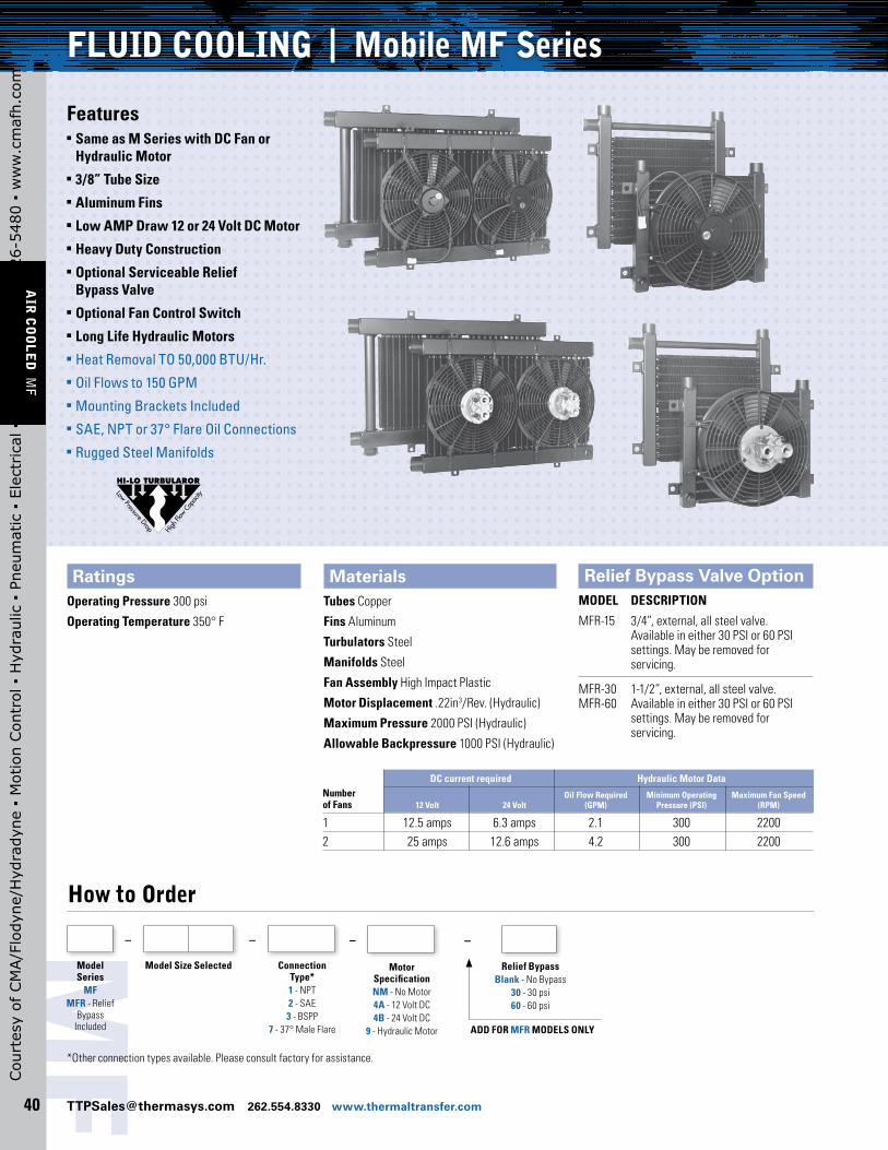
MotorSpecificationNM - No Motor4A - 12 Volt DC4B - 24 Volt DC
9 - Hydraulic Motor
–
*Other connection types available. Please consult factory for assistance.
How to Order
ModelSeries
MF MFR - Relief
Bypass Included
Model Size Selected
– –
ConnectionType*1 - NPT2 - SAE3 - BSPP
7 - 37° Male Flare
Relief BypassBlank - No Bypass
30 - 30 psi60 - 60 psi
–
ADD FOR MFR MODELS ONLY
Cou
rtes
y of
CM
A/F
lody
ne/H
ydra
dyne
▪ M
otio
n Con
trol
▪ H
ydra
ulic
▪ P
neum
atic
▪ E
lect
rica
l ▪ M
echa
nica
l ▪ (
800)
426
-548
0 ▪
ww
w.c
maf
h.co
m

MF
www.thermaltransfer.com [email protected] 262.554.8330 41
AIR
CO
OL
ED
MF
Dimensions - 12 & 24 Volt DC MotorsModels MF-15 and MF-30
3/8 NPT PORTFOR OPTIONALTEMP SENSOR
E
D
J
RELIEF BYPASS
C
H
G
.53 DIA4 HOLES
IN
B
F
A
FLOW
AIR FLOW
(2 PLACES)POWER LEAD 12" LONG
MF-15MF-30MF-60
13.8816.5830.83
15.8818.8333.08
21.12
15.75
19.75
17.41 274178
1.883.065.68
4.99
6.10
17.25
21.25
14.25
17.25
1.50 SQ
2.50 SQ 9.00
18.00
3/8 NPT PORTFOR OPTIONALTEMP SENSOR
MF MFR MF MFR
AIR FLOW
A
B
C
F
GH
ED
IN
(2 PLACES)JRELIEF BYPASS VALVE (OPTIONAL)
POWER LEADS12" LONG
VALVE (OPTIONAL)
1.00
1.50
#16
#24
NPT SAE
FLOW
.53 DIA
4 HOLES
J SHIPPING WEIGHTHE F GC D
BAMODEL
Units shown with optional bypass valve
3/8 NPT PORTFOR OPTIONALTEMP. SENSOR
E
D
J
H
G
IN
B
F
A
FLOW
AIR FLOW
(2 PLACES)
RELIEF BYPASSVALVE (OPTIONAL).53 DIA
4 HOLES
.53 DIA4 HOLES
#8 SAE TYP IN2.06
C
CK
K
A
B
F
GH
ED
IN
(2 PLACES)
FLOW
RELIEF BYPASS VALVE (OPTIONAL)
3/8 NPT PORTFOR OPTIONALTEMP. SENSOR
2.06
14.25
AIR FLOW
J
#8 SAE TYP IN
MF-15MF-30MF-60
13.8816.5830.83
15.8818.8333.08
21.12
15.75
19.75
17.41 274178
1.883.065.68
7.87
8.96
17.25
21.25
14.25
17.25
1.50 SQ
2.50 SQ 9.00
18.00
MF MFR MF MFR1.00
1.50
#16
#24
NPT SAEJ SHIPPING
WEIGHTHE F GC DBA
MODEL
Model MF-60
Models MF-15 and MF-30 Model MF-60
3/8 NPT PORTFOR OPTIONALTEMP SENSOR
E
D
J
RELIEF BYPASS
C
H
G
.53 DIA4 HOLES
IN
B
F
A
FLOW
AIR FLOW
(2 PLACES)POWER LEAD 12" LONG
MF-15MF-30MF-60
13.8816.5830.83
15.8818.8333.08
21.12
15.75
19.75
17.41 274178
1.883.065.68
4.99
6.10
17.25
21.25
14.25
17.25
1.50 SQ
2.50 SQ 9.00
18.00
3/8 NPT PORTFOR OPTIONALTEMP SENSOR
MF MFR MF MFR
AIR FLOW
A
B
C
F
GH
ED
IN
(2 PLACES)JRELIEF BYPASS VALVE (OPTIONAL)
POWER LEADS12" LONG
VALVE (OPTIONAL)
1.00
1.50
#16
#24
NPT SAE
FLOW
.53 DIA
4 HOLES
J SHIPPING WEIGHTHE F GC D
BAMODEL
3/8 NPT PORTFOR OPTIONALTEMP SENSOR
E
D
J
RELIEF BYPASS
C
H
G
.53 DIA4 HOLES
IN
B
F
A
FLOW
AIR FLOW
(2 PLACES)POWER LEAD 12" LONG
MF-15MF-30MF-60
13.8816.5830.83
15.8818.8333.08
21.12
15.75
19.75
17.41 274178
1.883.065.68
4.99
6.10
17.25
21.25
14.25
17.25
1.50 SQ
2.50 SQ 9.00
18.00
3/8 NPT PORTFOR OPTIONALTEMP SENSOR
MF MFR MF MFR
AIR FLOW
A
B
C
F
GH
ED
IN
(2 PLACES)JRELIEF BYPASS VALVE (OPTIONAL)
POWER LEADS12" LONG
VALVE (OPTIONAL)
1.00
1.50
#16
#24
NPT SAE
FLOW
.53 DIA
4 HOLES
J SHIPPING WEIGHTHE F GC D
BAMODEL
Units shown with optional bypass valve
3/8 NPT PORTFOR OPTIONALTEMP. SENSOR
E
D
J
H
G
IN
B
F
A
FLOW
AIR FLOW
(2 PLACES)
RELIEF BYPASSVALVE (OPTIONAL).53 DIA
4 HOLES
.53 DIA4 HOLES
#8 SAE TYP IN2.06
C
CK
K
A
B
F
GH
ED
IN
(2 PLACES)
FLOW
RELIEF BYPASS VALVE (OPTIONAL)
3/8 NPT PORTFOR OPTIONALTEMP. SENSOR
2.06
14.25
AIR FLOW
J
#8 SAE TYP IN
MF-15MF-30MF-60
13.8816.5830.83
15.8818.8333.08
21.12
15.75
19.75
17.41 274178
1.883.065.68
7.87
8.96
17.25
21.25
14.25
17.25
1.50 SQ
2.50 SQ 9.00
18.00
MF MFR MF MFR1.00
1.50
#16
#24
NPT SAEJ SHIPPING
WEIGHTHE F GC DBA
MODEL
3/8 NPT PORTFOR OPTIONALTEMP. SENSOR
E
D
J
H
G
IN
B
F
A
FLOW
AIR FLOW
(2 PLACES)
RELIEF BYPASSVALVE (OPTIONAL).53 DIA
4 HOLES
.53 DIA4 HOLES
#8 SAE TYP IN2.06
C
CK
K
A
B
F
GH
ED
IN
(2 PLACES)
FLOW
RELIEF BYPASS VALVE (OPTIONAL)
3/8 NPT PORTFOR OPTIONALTEMP. SENSOR
2.06
14.25
AIR FLOW
J
#8 SAE TYP IN
MF-15MF-30MF-60
13.8816.5830.83
15.8818.8333.08
21.12
15.75
19.75
17.41 274178
1.883.065.68
7.87
8.96
17.25
21.25
14.25
17.25
1.50 SQ
2.50 SQ 9.00
18.00
MF MFR MF MFR1.00
1.50
#16
#24
NPT SAEJ SHIPPING
WEIGHTHE F GC DBA
MODEL
Note: All dimensions are in inches. We reserve the right to make reasonable design changes without notice. *Inlet and outlet oil connections can be reversed when the bypass valve is not used.
Note: All dimensions are in inches. We reserve the right to make reasonable design changes without notice. *Inlet and outlet oil connections can be reversed when the bypass valve is not used.
Dimensions - Hydraulic Motors
Cou
rtes
y of
CM
A/F
lody
ne/H
ydra
dyne
▪ M
otio
n Con
trol
▪ H
ydra
ulic
▪ P
neum
atic
▪ E
lect
rica
l ▪ M
echa
nica
l ▪ (
800)
426
-548
0 ▪
ww
w.c
maf
h.co
m
MF
[email protected] 262.554.8330 www.thermaltransfer.com42
AIR
CO
OL
ED
MF
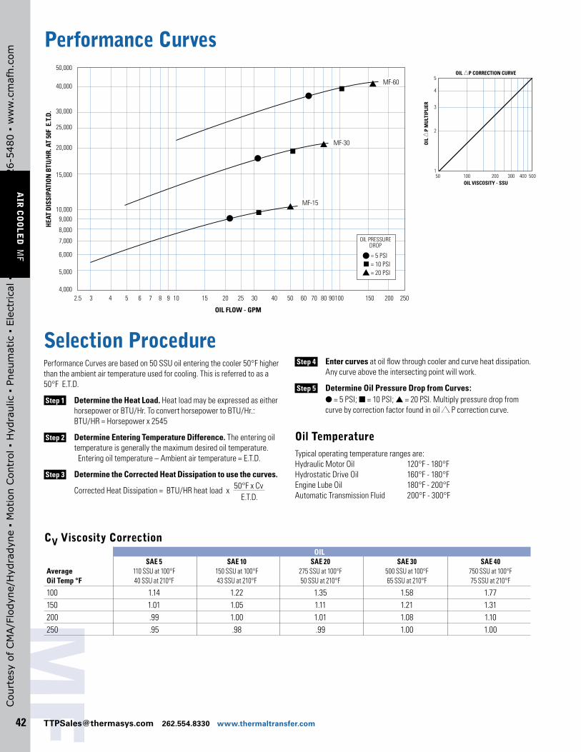
Performance Curves
30,000
40,000
50,000
25,000
20,000
15,000
10,0009,000
8,000
7,000
6,000
5,000
4,0002.5 3 4 5 6 7 8 9 10 15 20 25 30 40 50 60 70 80 90100 150 200 250
OIL FLOW - GPM
HEA
T D
ISSI
PATI
ON
BTU
/HR.
AT
50F
E.T
.D.
OIL PRESSUREDROP
= 5 PSI= 10 PSI= 20 PSI
MF-60
MF-30
MF-15
5
4
3
2
150 60 70 80 90 100 200 400300 500150
OIL
P M
ULT
IPLI
ER
OIL VISCOSITY - SSU
OIL P CORRECTION CURVE
Selection ProcedurePerformance Curves are based on 50 SSU oil entering the cooler 50°F higher than the ambient air temperature used for cooling. This is referred to as a 50°F E.T.D.
Step 1 Determine the Heat Load. Heat load may be expressed as either horsepower or BTU/Hr. To convert horsepower to BTU/Hr.: BTU/HR = Horsepower x 2545
Step 2 Determine Entering Temperature Difference. The entering oil temperature is generally the maximum desired oil temperature. Entering oil temperature – Ambient air temperature = E.T.D.
Step 3 Determine the Corrected Heat Dissipation to use the curves.
Corrected Heat Dissipation = BTU/HR heat load x 50°F x Cv
E.T.D.
Step 4 Enter curves at oil flow through cooler and curve heat dissipation. Any curve above the intersecting point will work.
Step 5 Determine Oil Pressure Drop from Curves: l = 5 PSI; n = 10 PSI; s = 20 PSI. Multiply pressure drop from curve by correction factor found in oil s P correction curve.
Oil TemperatureTypical operating temperature ranges are: Hydraulic Motor Oil 120°F - 180°F Hydrostatic Drive Oil 160°F - 180°F Engine Lube Oil 180°F - 200°F Automatic Transmission Fluid 200°F - 300°F
CV Viscosity Correction OiL SAE 5 SAE 10 SAE 20 SAE 30 SAE 40Average 110 SSU at 100°F 150 SSU at 100°F 275 SSU at 100°F 500 SSU at 100°F 750 SSU at 100°FOil Temp °F 40 SSU at 210°F 43 SSU at 210°F 50 SSU at 210°F 65 SSU at 210°F 75 SSU at 210°F
100 1.14 1.22 1.35 1.58 1.77150 1.01 1.05 1.11 1.21 1.31200 .99 1.00 1.01 1.08 1.10250 .95 .98 .99 1.00 1.00
50 100 002 003 500
5
1
2
3
4
OIL
P
MU
LTIP
LIER
OIL VISCOSITY - SSU
OIL P CORRECTION CURVE
400
Cou
rtes
y of
CM
A/F
lody
ne/H
ydra
dyne
▪ M
otio
n Con
trol
▪ H
ydra
ulic
▪ P
neum
atic
▪ E
lect
rica
l ▪ M
echa
nica
l ▪ (
800)
426
-548
0 ▪
ww
w.c
maf
h.co
m
MF
www.thermaltransfer.com [email protected] 262.554.8330 43
AIR
CO
OL
ED
MF
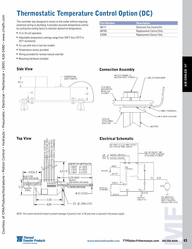
Thermostatic Temperature Control Option (DC)This controller was designed to mount on the cooler without requiring extensive wiring or plumbing. It provides accurate temperature control by cycling the cooling fan(s) to maintain desired oil temperature.n 12 or 24 volt operation n Adjustable temperature settings range from 100°F thru 210°F in
20°F increments n For use with one or two fan modelsn Temperature sensor providedn Wiring provided for remote manual overriden Mounting hardware included
Part Number Description 96171 Electronic Fan Control Kit 68790 Replacement Control Only 67699 Replacement Sensor Only
Side View
Electrical Schematic
.90 ±.2
TEMPERATURESELECT SWITCH
1.12.12
NOTE: This switch should be fused to prevent damage if ground is lost. A 30 amp fuse is required in the power supply.
Top View
Connection Assembly
Cou
rtes
y of
CM
A/F
lody
ne/H
ydra
dyne
▪ M
otio
n Con
trol
▪ H
ydra
ulic
▪ P
neum
atic
▪ E
lect
rica
l ▪ M
echa
nica
l ▪ (
800)
426
-548
0 ▪
ww
w.c
maf
h.co
m