Embed Size (px)
Citation preview
Fluid Design to Minimize Invasive DamageIn Horizontal Wells
D.B. BENNION, F.B. THOMAS, D.W. BENNION, R.F. BIETZHycal Energy Research Laboratories Ltd.
injectivity of a water or gas injection well.Invasive formation damage can occur by the introduction of:a) Foreign potentially incompatible fluids into the formation.b) Natural or artificial solids.c) Extraneous immiscible phases.d) Physical mechanical damage.Further information on some of the specific mechanisms of
these various types of invasive damage will be elucidated uponlater in the paper.
AbstractFonnation damage is a very reservoir specific process, but
extensive studies indicate that generalities can often be drawn withrespect to certain types and mechanisms of damage which aremore prevalent with various reservoir types. This paper providesa mechanistic discussion of various types of fonnation damagecommon to horizontal wells, such as fluid-fluid and rock-fluidincompatibilities, solids invasion, effect of overbalance pressure,aqueous phase trapping, chemical adsorption, wettabilityalteration, microbiological activity, and fines migration. Thesephenomena are discussed and how they specifically relate to thefollowing fonnation types:
1. Clean and dirty homogeneous sands2. Clean and dirty laminated sands3. Unconsolidated sands4. Fractured sands5. Homogeneous carbonates6. Fractured carbonates7. Vugular carbonatesRecommendations for various fluid types and procedures which
have experienced success in certain situations are also presented.Laboratory testing of fluids and representative core samples ishighlighted as a potential diagnostic tool to select the optimumfluids for drilling, completion, stimulation and workovertreatments. Use of these guidelines can, in many cases, narrowthe choice of potential fluids considered for use in a givenlithofacies type and increase the efficiency of the optimization
process.
Formation Damage in Horizontal vs.Vertical Wells
A detailed discussion of mechanisms of formation damage inhorizontal wells has been presented(!). Formation damage tendsto be more significant in horizontal vs vertical wells for a numberof reasons, some of these being:
I. Longer fluid exposure time to the formation during drillingand greater potential depth of invasion in situations wheresustained fluid and solids losses to the formation are
apparent.2. The majority of horizontal wells remain as open hole or
slotted liner completions. Therefor shallow damage, whichwould normally be perforated through in a typical verticalcompletion, may remain as an impermeable or lowpermeability barrier to oil or gas flow.
3. Drawdowns applied in many horizontal wells result inselective cleanup of a small portion of the total exposedavailable flow area, causing the majority of the productionfrom a relatively small fraction of the exposed well boreface.
4. Selective stimulation in wells where slotted liners are inplace is inefficient. Extensive stimulation of any horizontalsection is generally difficult and expensive in comparison toa vertical well, and hence many stimulation programs areineffective due to cost and/or time limitations.
IntroductionHorizontal drilling is being utilized in an ever increasing fash-
ion to exploit reservoirs exhibiting thin pay zones, problems withwater or gas coning, to obtain greater reservoir exposure and tomaximize the productive potential of naturally fractured reservoirs.Reductions in the productivity of these horizontal wells due toimproperly or inadequately designed drilling, completion orworkover programs is a frequent occurrence. This paper docu-ments common areas for potential reductions in the productivityof horizontal wells completed in oil or gas bearing formations dueto invasive formation damage and provides general criteria for thedesign and selection offluids and operating programs to minimizepotential damage.
Processes WhichDamage
Most procedures which result in the contact of the formation byforeign fluids or solids have a potential for permeabilityimpairment. The most common of these would include:
a) Drillingb) Completion proceduresc) Workoverlkill proceduresd) Stimulation procedurese) Injection procedures (secondary or tertiary EOR and
disposal processes)Some of the common damage mechanisms associated with
these processes will now be elaborated upon.
Cause Formation
Invasive Formation DamageFormation damage can be described as any phenomenon
induced by the drilling, completion or stimulation process or byregular operations resulting in a permanent reduction in the pro-ductivity of a producing oil or gas well or the reduction in the
45November 1996. Volume 35. No.9
Acid solutions generally need to be carefully screened to avoidproblems with emulsions, precipitates, sludges or the release ofinsoluble fines from the formation. Oxidizing agents, solvents,mutual solvents, etc., must also be carefully evaluated to ensurethat they have the desired effect on the damage present and willnot be ineffective, or perhaps cause further reductions inproductivity.
Common Dama~ Mechanisms(Workovers/Kill rlUidS)
Similar caution must be exercised in the selection of appropri-ate workoverlkill fluids. This is especially important since if asuccessful completion has occurred, the screening filter cakeinhibiting fluid losses to the formation has been removed and thepotential for invasive damage becomes more severe in an overbal-anced situation.
Common Damage Mechanisms - InjectionInjection processes could include the injection of water for sec-
ondary recovery projects or disposal of produced water, or theinjection of gas associated with tertiary oil recovery processes, gascycling processes or gas storage reservoirs. Potential damagemechanisms in these areas could include:
For Water Injection
1. Fluid-Fluid incompatibilities (scales, precipitates, etc.).2. Rock-fluid incompatibilities.3. Solids invasion due to insufficient filtration of injected
fluids.4. Fines mobilization caused by excessive injection rates.5. Introduction of an extraneous hydrocarbon phase (i.e. non-
removed skim oil, trace hydrocarbon contaminants, etc.).6. Introduction of adverse bacterial agents.
For Gas Injection1. Gas-Fluid incompatibilities (i.e. chemical reaction to form
asphaltenes, etc.).2. Atomized oil carryover (from compressors) and subsequent
entrainment in the near well bore region.
Recommended SpecificReservoir Types
Formation damage is extremely reservoir specific and it isimpossible to definitively classify or generalize if a particulardamage mechanism will be predominant in one reservoir com-pared to another without laboratory and field quantification.However, extensive lab and field experiments have indicated thatcertain types of damage are more prevalent in certain reservoirsystems than others. This, therefore, provides a starting pointfrom which to consider the design of drilling, completion and sti-mulation programs, thereby narrowing the scope of work requiredand the alternatives which need to be addressed.
Six broad classifications of general reservoir tYpes will beaddressed in this paper, these being:
I. Homogeneous consolidated sandstone reservoirs2. Laminated consolidated sandstone reservoirs.3. Unconsolidated high permeabilitY sandstone reservoirs.4. Fractured sandstone reservoirs.5. Homogeneous carbonate reservoirs.6. Fractured/vugular carbonate reservoirs.
Procedures for
Common Damage Mechanisms(Completion ana Stimulation)
Many of the problems associated with drilling fluids such as
fluid-fluid and rock-fluid incompatibility, solids invasion (if dirtyfluids are utilized) phase trapping/blocking, chemical adsorption,etc. are also potential problems associated with completion fluids.
Homogenous Sandstone ReservoirsMajor potential damage mechanisms which have often been
found to be prevalent in these types of reservoirs include:
The Journal of Canadian Petroleum Technology46
~E8'nIIFllr8le 8M1
10 ~ p.-'-1.3 mil7on ~
1 0 mIaoo 188'"1 mk:ton &
.1 0 mCroo 10mk:ron~a-
-'-soIc8~Extem8/
.. For 5mB. Finel&F-.
nGURE 1: Solids invasion into a bomogeneolls pore system.
1. Fluid-fluid compatibility IX'oblems(perticulariy severe if thesand matrix is of low permeability and porosity).
2. Rock-fluid compatibility (particularly severe if low cationconcentration brines are utilized in conjunction with highconcentrations of smectite or kaolinite clay). If low clayconcentrations are present (i.e., <2% bulk fraction),rock-fluid compatibility problems may be less of a concern.Rock-fluid compatibility problems in sandstones tend to beminimized in high reservoir qualities over 1000 InD.
3. Solids invasion may be a problem, depending on the size ofthe suspended solids. solids composition, overbalance pres-sure and median pore throat diameter of the target forma-tion. In general solids greater than about 2S - 300/0 of thediameter of the pores under consideration will not deeplyinvade a homogenous sand under mild to moderate (i.e.,<3S00 psi) overbalance conditions. Operation at moresevere overbalance conditions can result in physicalentrainment of larger solids or a high concentration ofinvaded smalla- solids. In fine grained fonn_OIIS. total
sealoff of mud filtrate with fonnation solids and artificialbridging agents may be difficult as the size distribution ofbridging agent required may be extremely fme andcommercially unavailable (i.e., - 325 mesh bridging agentsnonnaJly represent some of the smallest of thecommercially available bridging materials).Consideration of the type of potential completion techniquesavailable should also be given in the selection of artificialbridging agents. Biodegradable agents, such as cellulose oroil soluble resins may be considered in sandstoneapplications or other situations when conventional acidizingtreatments may have a minimal stimulation impact on therock matrix. If ultimate acidization is a consideration. suchas in limestone or some dolomitizcd fonnations, acidsoluble bridging agents, such as sized CaCO3, may be aviable consideration. In fonnations expected to producewater, saturated salt or hydrocarbon based fluids containingsized NaCI (sodium chloride) have also met with somesuccess. Figure 2 provides an illustration of the mechanismof solids invasion into a homogeneous pore system.
4. High overbalance pressures can be damaging inhomogeneous sands, particularly if the bridging action ofthe filter cake is poor which can result in high, sustainedfiltrate losses to the fonnation and a deep invasion of apotentially damaging filtrate or solids. This problem ismore ofa concern in higher penneability consolidated sandswhere a bridging and totally sealing filter cake may bedifficult to fOnD.
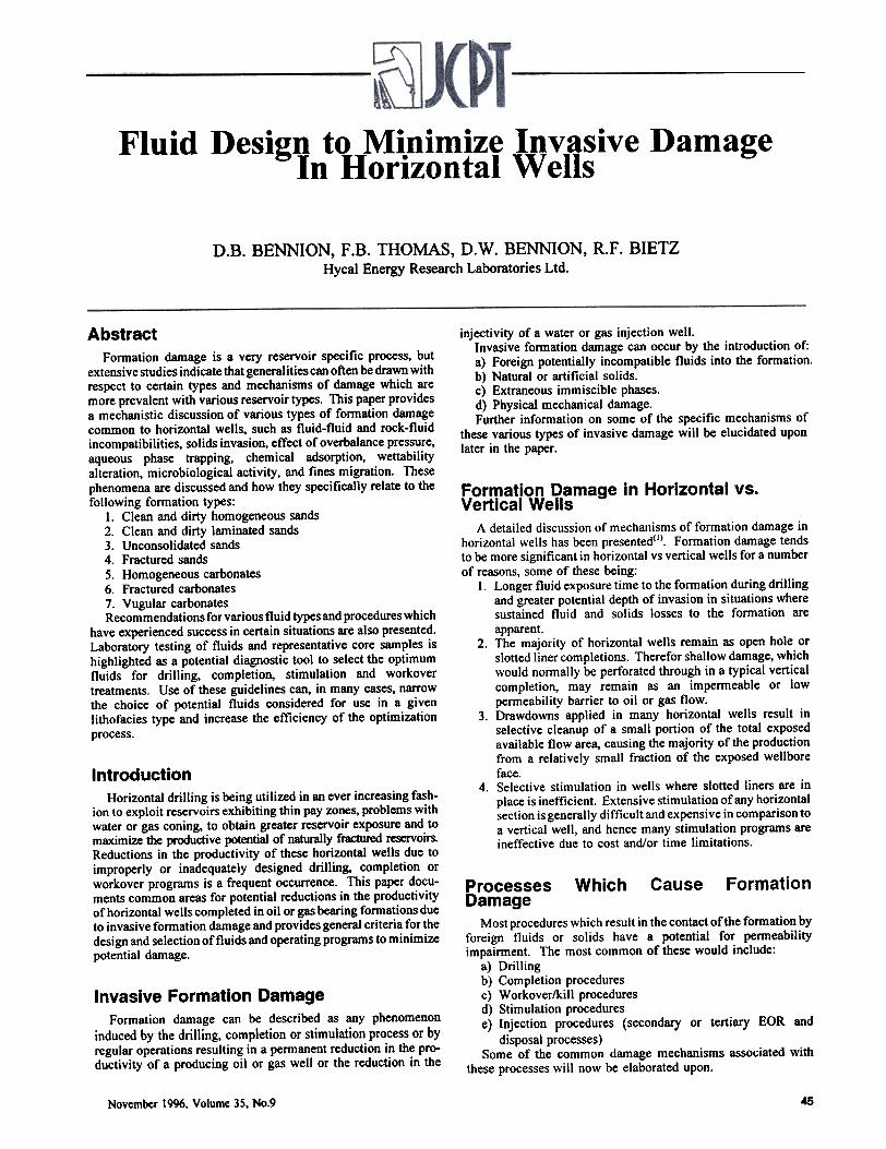
5. Phase trapping can be a significant source of penneabilityimpainnent in lower penneability consolidated sands whichexhibit abnonnally low initial water saturations in either oilor gas reservoirs. Figures 2 and 3 provide a schematicillustration of the reducing effect of an entrapped watersaturation on gas penneability. The severity of the phasetrap is affected by the configuration of the oil or gas phaserelative penncability curve at low water saturation levelsand the relative difference between the "initial" watersaturation and the final "irreducible. water saturationobtained. General rule of thumb guidelines for phasetrapping in matrix penneability oil or gas reservoirs arcprovided in Table I.
6. Homogeneous sands, particularly those containing highconcentrations of high surface area clays, can be susceptibleto reductions in penneability and alterations in wcttabilitydue to chemical adsorption. Detailed lab evaluations of theeffect of chemical contact on such fonnations, particularlydirty sands of less than 100 mD penneability, are highlyrecommended.
7. Fines mobilization in homoacncous sands can be a problemliven conditions of:
1. Initial abnom1aI/y low SWi
(i.e. 10%)2. Rush m maxinun ~
(I.e. 80%)3. Can ~ only ~
Sw to 65%
'JI FIGURE 2: Pofe scale mechanism or aq.eou
pbase trapping in low Swi gas rcservoin. ~
November 1996, Volume 35, No.9 47
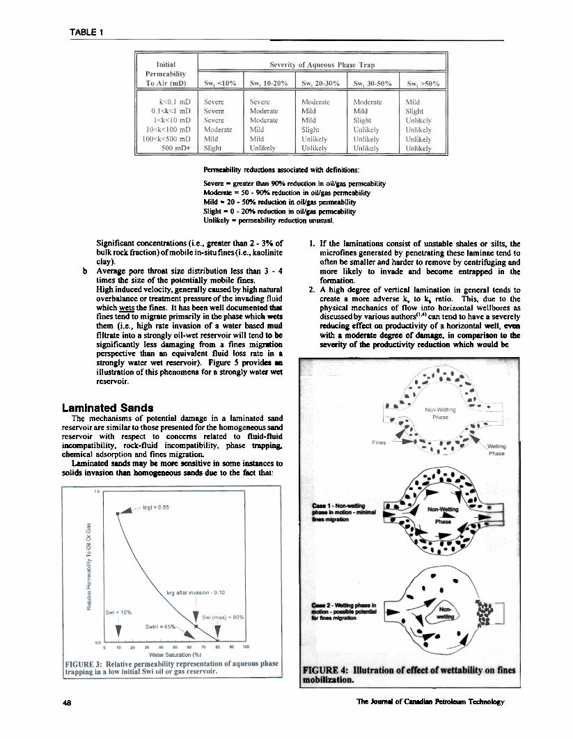
TABLE 1
Permelbility reductions associated with defmitions:
Severe - greater than 90-/0 reduction in oil/gas permeabilityModerate - 50 . 900/. reduction in oil/gas permeabilityMild - 20 - 50% reduction in oil/gas penneabilitySlight - 0 - 20% reduction in oil/gas penneabilityUnlikely - permeability reduction unusual.
b
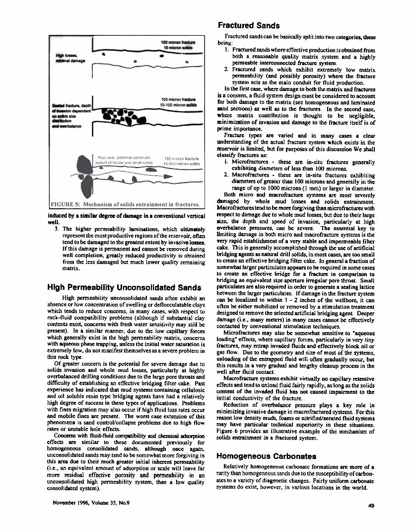
Significant concentrations (i.e., greater than 2 - 3% ofbulk rock fraction) of mobile in-situ fines (i.e., kaoliniteclay).Average pore throat size distribution less than 3 - 4times the size of the potentially mobile fines.High induced velocity, generally caused by high naturaloverbalance or treatment pressure of the invading fluidwhich wets the fines. It has been well documented thatfines teDdto migrate primarily in the phase which wetsthem (i.e., high rate invasion of a water based mudfiltrate into a strongly oil-wet reservoir will tend to besignificantly less damaging from a fines migr8tionperspective than an equivalent fluid loss rate in .strongly water wet reservoir). Figure 5 provides 81illustration of this phenomena for a strongly water wetreservoir.
I. If the laminations consist of unstable shales or silts, themicrofines generated by penetrating these laminae tend tooften be smaller and harder to remove by centrifuging andmore likely to invade and become entrapped in thefonnation.
2. A high degree of vertical lamination in general tends tocreate a more adverse k. to k.. ratio. This, due to thephysical mechanics of flow into horizontal well bores asdiscussed by various authors"'.) can tend to have a severelyreducing effec:t on productivity of a horizontal well, evenwith a moderate degree of damage, in comparison to theseverity of the productivity reduction which would be
Laminated SandsThe mechanisms of potential damage in a laminated sand
reservoir are similar to those presented for the homogeneous sandreservoir with respect to concerns related to fluid-fluid~patibility, rock-fluid incompatibility, phase trapping.chemical adsorption and fines migration.
Laminated sands may be more sensitive in some instances tosolids invasion than bomoaencous sands due to the fact that: .,.~--'-_a ..."
C-1.~~ .::- m~m:n - ~ ~~~
~ . -..,...
~ t;Y--~ .. -n-.''-'-- ~ .
. ..,-~c..2.~~..
8oIIon . pc8I* IX*n68I- fin.. migration
NOIto'
., C---~
.~."'.
I""
AI FIG URE 4: Illutration of effect of wettability on finesmobilization.
"nte Joumll of Clnldian Petroleum Technolocy48
Fractured SandsFractured sands can be basically split into two categories, these
being:
--~~.I dn.ge
100 mUon Ir-..10-100 miaoo--~ tacbn. dII*Il
~--klnd8pend81t
---sa~
~.l8ra
induced by a similar dcgr= of dlmagc in a conventional verticalwell.
3. The higher penneability laminations, which ultimltclyrepresent the most productive regions of the reservoir, oftentend to be damaged to the greatest extent by invasive losses.If this damage is penn anent and cannot be removed duringwell completion, greatly reduced productivity is obtainedfrom the less damaged but much lower quality remainingmatrix.
1. Fractured sands where effective production is obtained ftomboth a reasonable quality matrix system and a highlypermeable interconnected fiacture system.
2. Fractured sands which exhibit extremely low matrixpermeability (and possibly porosity) where the fracturesystem acts as the main conduit for fluid production.
In the first case, where damage to both the matrix and fiacturesis a concern, a fluid system design must be considered to accountfor both damage to the matrix (see homogeneous and laminatedand sections) as well as to the fractures. In the second case,where matrix contribution is thought to be negligible,minimization of invasion and damage to the fracture itself is ofprime importance.
Fracture types are varied and in many cases a clearWlderstanding of the actual fracture system which exists in the~servoir is limited, but for purposes of this discussion We shallclassify fractures as:
1. Microfracturcs - these are in-situ fractures generallyexhibiting diameters of less than 100 microns.
2. Macrofractures . these are in-situ fractures exhibitingdiameters of greater than 100 microns and generally in therange of up to 1000 microns (1 mm) or larger in diameter.
Both micro and macrofracture systems are most severelydamaged by whole mud losses and solids entrainment.Macrofractures tend to be more forgiving than microfractures withrespect to damage due to whole mud losses, but due to their largesize, the depth and speed of invasion, particularly at highoverbalance pressures, can be severe. The essential key tolimiting damage in both micro and macrofiacture systems is thevery rapid establishment of a very stable and impermeable filtercake. This is generally accomplished through the use of artificialbridging agents as natural drill solids, in most cases, are too smallto create an effective bridging filter cake. In general a fiaction ofsomewhat larger particulates appears to be required in some casesto create an effective bridge for a fracture in comparison tobridging an equivalent size aperture irregular pore throat. Smallparticulates are also required in order to generate a sealing latticebetween the larger particulates. If damage in the fracture systemcan be localized to within 1 - 2 inches of the wellbore, it canoften be either mobilized or removed by a stimulation treatmentdesigned to remove the selected artificial bridging agent. Deeperdamage (i.e., many meters) in many cases cannot be effectivelycontacted by conventional stimulation techniques.
Microfractures may also be somewhat sensitive to Maqueousloading" effects, where capillary forces, particularly in very tinyfractures, may entrap invaded fluids and effectively block oil orgas flow. Due to the geometry and size of most of the systems,unloading of the entrapped fluid will often gradually occur, butthis results in a very gradual and lengthy cleanup process in thewell after fluid contact.
Macrofracture systems exhibit virtually no capillary retentiveeffects and tend to unload fluid fairly rapidly, as long as the solidscontent of the invaded fluid has not caused impairment to theinitial conductivity of the fracture.
Reduction of overbalance pressure plays a key role inminimizing invasive damage in macrofractured systems. For thisreason low density muds, foams or nitrified/aerated fluid systemsmay have particular technical superiority in these situations.Figure 6 provides an illustrative example of the mechanism ofsolids entrainment in a fractured system.
High Permeability Unconsolidated SandsHigh penneability unconsolidated sands often exhibit an
absence or low concentration of swelling or deflocculatable clayswhich tends to reduce concerns, in many cases, with respect torock-fluid compatibility problems (although if substantial claycontents exist. concerns with fresh water sensitivity may still bepresent). In a similar manner, due to the low capillary forceswhich generally exist in the high penneability matrix, concernswith aqueous phase trapping, unless the initial water saturation isextremely low, do not manifest themselves as a severe problem inthis rock type.
Of greater concern is the potential for severe damage due tosolids invasion and whole mud losses, particularly at highlyoverbalanced drilling conditions due to the large pore throats anddifficulty of establishing an effective bridging filter cake. Pastexperience has indicated that mud systems containing cellulosicand oil soluble resin type bridging agents have had a relativelyhigh degree of success in these types of applications. Problemswith fines migration may also occur if high fluid loss rates occurand mobile fines are present. The worst case extension of thisphenomena is sand control/collapse problems due to high flowrates or unstable hole effects.
Concerns with fluid-fluid C(Xnpaboility and chemical ~effects are similar to these documented previously forhomogeneous consolidated sands, although once again.unconsolidated sands may tend to be somewhat more forgiving inthis area due to their much greater initial inherent penneability(i.e., an equivalent amount of adsorption or scale will leave farmore residual effective porosity and permeability in anunconsolidated high permeability system, than a low qualityconsolidated system).
Homogeneous CarbonatesRelatively homogeneous carbonate formations are more of a
rarity than homogeneous sands due to the susceptibility of carbon-ates to a variety of diagenetic changes. Fairly uniform carbonatesystems do exist, however, in various locations in the world.
November 1996, Volume 35, No.949
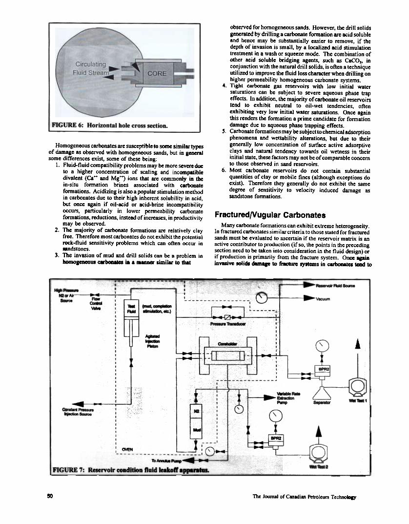
I FIGURE 6: Horizontal hole cross section.
observed for homogeneous sands. However. the drill solidsgenerated by drilling a carbonate formation are acid solubleand hence may be substantially easier to remove, if thedepth of invasion is small. by a localized acid stimulationtreatment in a wash or squeeze mode. The combination ofother acid soluble bridging agents. such as CacoJ, inconjunction with the natural drill solids, is often a techniqueutilized to improve the fluid loss character when drilling onhigher permeability homogeneous carbonate systems.
4. Tight carbonate gas reservoirs with low initial watersaturations can be subject to severe aqueous phase trapeffects. In addition, the majority of carbonate oil reservoirstend to exhibit neutral to oil-wet tendencies, oftenexhibiting very low initial water saturations. Once againthis renders the formation a prime candidate for formationdamage due to aqueous phase trapping effects.
S. Carbonate formations may be subject to chemical adsorptionphenomena and wettability alterations, but due to theirgenerally low concentration of surface active adsorptiveclays and natural tendency towards oil wetness in theirinitial state, these factors may not be of comparable concernto those observed in sand reservoirs.
6. Most carbonate reservoirs do not contain substantialquantities of clay or mobile fmes (although exceptions doexist). Therefore they generally do not exhibit the samedegree of sensitivity to velocity induced damage assandstone formations.
Fractured/Vugular CarbonatesMany carbonate fonnations can exhibit extreme heterogeneity.
In fractured carbonates similar criteria to those stated for fracturedsands must be evaluated to ascertain if the reservoir matrix is anactive contributor to production (if so, the points in the precedingsection need to be taken into consideration in the fluid design) orif production is primarily from the fracture system. Once IpininvlSivc solids dam. to fracture systems in ~ tend to
Homogeneous carbonates are susceptible to some similar typesof damage as observed with homogeneous sands, but in generalsome differences exist, some of these being:
I. Fluid-f1uid compatibility problems may be more severe dueto a higher concentration of scaling and incompatibledivalent (Ca++ and Mg++) ions that are commonly in thein-situ formation brines associated with carbonateformations. Acidizing is also a popular stimulation methodin carbonates due to their high inherent solubility in acid,but once again if oil-acid or acid-brine incompatibilityoccurs, particularly in lower permeability carbonateformations, reductions, instead of increases, in productivitymay be observed.
2. The majority of carbonate formations are relatively clayfree. Therefore most carbonates do not exhibit the potentialrock-f1uid sensitivity problems which can often occur inandstones.
3. The invasion of mud and drill solids can be a problem inhomoaeDeOUl C8r~ in . maim« similar to that
--- ~ ...~'--
1GG'Ai"-~ FW
a..aw-.
V8CUin---Teet~
(mI-', ~8t8IUa\kIII, E.)
~"4'~T
AgI-.I~P-.1 ~
.
~
1::=t- t ;-
~
=Y -rg-_t[to i ~ R8PII-.
L
~ .~~~8OI81:e
-
~ ..Mud
I J ,--
' ~ : (To NwM PI-.'" ~.
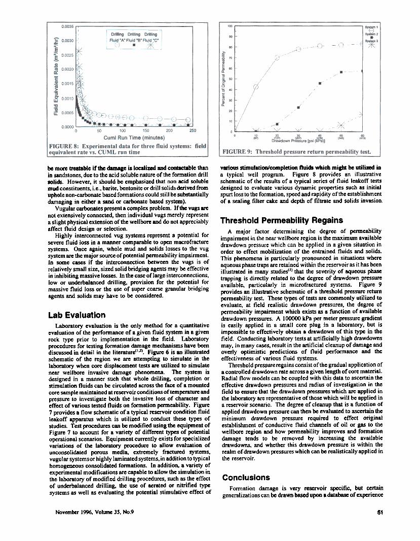
l FlG~ 7: Reservoir condition ftuid leakoft' appara~s.
-A-.
OJEH ~
-~-~.
eo The Journal of Canadian Petroleum TechnoDIY
various stimulation/completion fluids which miibt be utiliad iDa typical well program. Figure 8 provides an illustrativeschematic of the results of a typical series of fluid leakoff testsdesigned to evaluate various dynamic properties such as initialspurt loss to the formation, speed and rapidity of the establishmentof a sealing filter cake and depth of filtrate and solids invasion.
be more treatable if the damage is localized aDd contactable thanin sandstones, due to the acid soluble nature of the formation drillsolids. However, it should be emphasized that non Kid solublemud constituents, i.e., barite, bentonite or drill solids derived fromuphole non-carbonate based formations could still be substantiallydamaging in either a sand or carbonate based system).
Vugular carbonates present a complex problem. If the vugs arenot extensively connected, then individual vugs merely representa slight physical extension of the wellbore aDd do not appreciablyaffect fluid design or selection.
Highly interconnected vug systems represent a potential forsevere fluid loss in a manner comparable to open macrofracturesystems. Once again. whole mud and solids losses to the vugsystem are the major source of potential permeability impairment.In some cases if the interconnection between the vugs is ofrelatively small size, sized solid bridging agents may be effectivein inhibiting massive losses. In the case of large interconnections,low or underbalanced drilling, provision for the potential formassive fluid loss or the use of super coarse granular bridgingagents and solids may have to be considered.
Lab EvaluationLaboratory evaluation is the only method for a quantitative
evaluation of the performance of a given fluid system in a givenrock type prior to implementation in the field. Laboratoryprocedures for testing formation damage mechanisms have beendiscussed in detail in the literature(I,J). Fiaure 6 is an illustratedschematic of the region we are attempting to simulate in thelaboratory when core displacement tests are utilized to simulatenear wellbore invasive damage phenomena. The system isdesigned in a manner such that whole drilling, completion orstimulation fluids can be circulated across the face of a mountedcore sample maintained at reservoir conditions of temperature andpressure to investigate both the invasive loss of character andeffect of various tested fluids on formation permeability. Figure7 provides a flow schematic of a typical reservoir condition fluidleakoff apparatus which is utilized to conduct these types ofstudies. Test procedures can be modified using the equipment ofFigure 7 to account for a variety of different types of potentialoperational scenarios. Equipment currently exists for specializedvariations of the laboratory procedure to allow evaluation ofunconsolidated porous media, extremely fractured systems,vugular systemsor highly laminated systems, in addition to typicalhomogeneous consolidated formations. In addition, a variety ofexperimental modifications are capable to allow the simulation inthe laboratory of modified drilling procedures, such as the effectof underbalanced drilling, the use of aerated or nitrified typesystems as well as evaluating the potential stimulative effect of
Threshold Permeability RegainsA major factor determining the degree of permeability
impairment in the near wellbore region is the maximum availabledrawdown pressure which can be applied in a given situation inorder to effect mobilization of the entrained fluids and solids.This phenomena is particularly pronounced in situations whereaqueous phase traps are retained within the reservoir as it has beenillustrated in many studiesC~) that the severity of aqueous phasetrapping is directly related to the degree of drawdown pressureavailable, particularly in microfractured systems. Figure 9provides an illustrative schematic of a threshold pressure returnpermeability test These types of tests are commonly utilized toevaluate, at field realistic drawdown pressures, the degree ofpermeability impairment which exists as a function of availabledrawdown pressures. A I ()()()()() kPa per meter pressure gradientis easily applied in a small core plug in a laboratory, but isimpossible to effectively obtain a drawdown of this type in thefield. Conducting laboratory tests at artificially high drawdownsmay, in many cases, result in the artificial cleanup of damage andoverly optimistic predictions of fluid performance and theeffectiveness of various fluid systems.
Threshold pressure regains consist of the gradual application ofa controlled drawdown rate across a given length of core material.Radial flow models can be coupled with this data to ascertain theeffective drawdown pressures and radius of investigation in theficld to ensure that the drawdown pressures which are applied inthe laboratory are representative of those which will be applied ina reservoir scenario. The degree of cleanup that is a function ofapplied drawdown pressure can then be evaluated to ascertain theminimum drawdown pressure required to effect originalestablishment of conductive fluid channels of oil or gas to thewellbore region and how permeability improves and formationdamage tends to be removed by increasing the availabledrawdowns, and whether this drawdown pressure is within therealm of drawdown pressures which can be realistically applied inthe reservoir.
ConclusionsFormation damage is very reservoir specific. but certain
generalizations can be drawn based upon a database of experience
November 1996. Vohm1e 35. No.9 51