Embed Size (px)
Citation preview

Fluid Dynamics And Turbo Machines.Professor Dr Dhiman Chatterjee.
Department Of Mechanical Engineering.Indian Institute Of Technology Madras.
Part C.Module-2.Lecture-8.
Hydraulic Turbines: Pelton Turbine.
Good morning, I welcome you all for today’s discussion on hydraulic turbines. In the last
couple of lectures we talked about pumps and we talked about the classification of pumps. In
the same way we will start the discussion on hydraulic turbines by first making the
classification of hydraulic turbines. Before we go into hydraulic turbines, let me show you a
schematic or picture of hydroelectric power plant.
(Refer Slide Time: 0:55)
Many of us, maybe some of you have also visited some dams, you could see on one side of
the dam there will be a big pool of water, which we call the reservoir and through the dam, at
the base of the dam you will have a powerhouse which has a typically a turbine as shown
here. As water flows from the duct, it comes to the turbine, this is called the penstock, it
comes to the turbine, then these turbine blades will rotate, there is a generator connected at
the top which converts the rotations into electric current and then it goes out of the
powerhouse for distribution. And that is how we generate hydroelectricity.
Now it is not necessary in general that a hydraulic turbine will always have a dam, recent
works are showing on low head turbines with no dam or very small check dams or barrages.

But the turbines that we are going to discuss today in this lecture are all big turbines, so for
that dam and reservoir that were showing here schematically are essential components. So
that means that we need to classify the hydro power plant projects into certain categories.
(Refer Slide Time: 2:05)
These categories may vary from country to country. These numbers, the names remain same
pico, micro, mini, small, etc., the names remain same but these values that are given, the
capacity values can change from country to country, what I am showing is for India specific.
So in India we talk about pico powerplant stations or pico hydro power projects which
produces 5 kilowatt or below. This is basically used for a system where you produce power
locally and use it, it is not really for transmission and going for the grid, usually that is the
scenario.
Then we can have micro hydropower projects which is up to 100 kilowatts, between 101
kilowatt 2 megawatts, we can talk about mini hydropower projects, above 2 megawatts and
up to 25 megawatts we talk about small hydropower projects and above that we have the
large hydropower stations. So this is the classification which we normally have and for these
larger power stations, we really have the dams and the turbines that we are going to talk
about.
(Refer Slide Time: 3:18)
So some basic concepts that we need to be clear at the very beginning. In case of pump for
example we had talked about the head developed by the pump. Here we are talking about
what is the head utilised by the turbine. So we can say that there is a headrest level, you can
imagine that this headrest level is nothing but the reservoir we have talked about and there is
a tail rest level at the downstream side of the turbine and in between the headrest level and
the tail rest level we have a turbine which is installed. So we have a piping system which you
call the penstock which brings the water to the turbine.
Now you may say that this level difference, this geodetic level difference between the
headrest level and the tail rest level is the head available. Yes it is true it is the head available,
it is called the gross head or Hg in my notations. So this gross head is nothing but the
geodetic level difference between the headrest level and the tail rest level. However,
whenever there is a flow, there will be some losses associated with it, there can be
approached loss, there can be exit losses and hence what is available to the turbine for
extraction of power is not Hg.
What is available is the energy available with the fluid before it enters the turbine here and
the energy available with the flow as it leaves the turbine. And this is given by another
symbol called H net or H. So this H is called the net head as opposed to HG which is the
gross head. And the difference between the 2 is accounted for by the losses. I am not going to
what are the different losses that this stage, it is not required. So whenever we discuss about

the head utilised by the turbine, unless specifically mentioned, we always refer to the head or
the net head.
(Refer Slide Time: 5:22)
Thus we can say that net head or head is equal to HG - loss and this is strictly speaking
should be called net head but we use the term head. And we can say that if there are no losses
in the turbine, if you assume the turbine to be an idealised machine, which is not in reality,
then the ideal or the theoretical power that will be transmitted by this turbine is P theoretical,
PH here stands for theoretical or ideal is rho V dot gH.
But as we have discussed in thermodynamics and also when we talked about the different
losses in the earlier classes, we said that no machine can be hundred percent efficient, we also
discussed different losses that are present for example we talked about hydraulic losses, we
have talked about, inside the hydraulic losses we have talked about the friction losses as well
as a shock or incidence loss, we have talked about the leakage loss, we have talked about disc
friction loss, we have talked about return flow loss. Now return flow loss in case of turbine is
not very significant.
And the disc friction loss is generally applicable for turbines, except for the turbine which is
moving in air. So we will talk about Pelton turbine which actually moves in air. So you have
to account for these different losses. And what we ultimately get from the turbine is the
coupling power PC which is given by omega, the rotational speed times T. And the ratio of
the 2 is called the overall efficiency. This was already talked about when we discuss the

losses but I am bringing it here because this is the central concept that we have to keep in
mind.
(Refer Slide Time: 7:18)
The ideal power, the actual power and the efficiency. Okay. So now when we come to the
turbines, we can classify the turbines in different ways just like we can classify any Turbo
machines we have discussed in general. So we can say that based on head and discharge,
example qualitatively speaking I can say high head, medium head, low head or alternatively I
can say high volume flow rate, medium volume flow rate or low volume flow rate. But the
problem of this way of classifying is that how high is high, what is high and what is low,
these are not very well defined.
So we have to talk about in another way. I will come to that next. So right now we will talk
about based on the action of water on the moving blades and we can say that the turbines can
be classified into 2 categories, one is impulse type of turbine, another one is reaction type of
turbine. You already know the definition of impulse type of turbine, impulse type of hydraulic
turbine is a hydraulic turbine in which there is no change of static pressure in the impeller or
the runner or the rotor blades.
Reaction turbine is one in which there is a change in the pressure. So different types of
impulse turbines are possible Pelton turbine, Turgo turbine and Banki or crossflow turbine.
And similarly reaction turbines can be of different types Francis, Deriaz, propeller and
Kaplan. And you see that some of these Pelton, Francis and Kaplan are marked in red because

this is what I am going to cover in today’s lecture. We are going to talk about Pelton turbine,
in the next lecture, in the next class we will talk about Francis and Kaplan turbine.
(Refer Slide Time: 9:23)
So in this course on fluid dynamics and Turbo machines we are going to cover these 3
turbines in some detail. I will touch upon propeller turbine in the next lecture as well. So we
continue with the classification of hydraulic turbines. We can say based on the direction of
flow of water in the runner and we can say it can be a tangential flow, in case of Pelton
turbine, this will become clear when we see the picture of Pelton turbine or it can be mixed
flow in case of Francis or axial flow in case of Kaplan or propeller turbine.
So this picture will become clearer when we talk about the different turbines in some detail.
And we can also tell based on the arrangement of the turbine shaft, the shaft can be arranged
in the vertical or in the horizontal direction.

(Refer Slide Time: 10:02)
But the best way of classifying Turbo machine as we have already discussed is based on the
specific speed or shape number. We will use the specific speed definition here for hydraulic
turbine. And based on it we can say that if the specific speed range is between 10 and 35 we
would prefer Pelton turbine. If it is between 60 and 300, it is Francis turbine and above 300 it
is usually Kaplan turbine. And to remind you, this definition of specific speed Ns is given as
N under root PC which is the coupling power whole divided by H to the power 5 by 4.
Please note that it is 5 by 4, whereas in case pump in the last class we have talked about with
H the power three fourth. And also please note that this coupling power is in metric
horsepower which is you can always convert from watt or kilowatt into metric horsepower.
Then N is in RPM and H is in meters. Now you may say what is wrong if I use Pelton turbine
in case of let us say a specific speed in the range of 120 to 180. The reason is that you will not
get the best efficiency. So we are talking about using a particular type of turbine where the
efficiency should be highest. So that has to be always kept in mind while determining which
turbine is more appropriate.

(Refer Slide Time: 11:36)
So some of the hydraulic turbine installations in India are, I have just given examples where
Pelton, Francis or Kaplan turbines are involved. Pelton turbine is seen in Mussoorie
hydroelectric powerplant on the Kiarkuli River, the Francis turbine is seen in the Bhakra dam
and Kaplan turbine is found in the Hirakud dam. These some of the values of the operating
conditions are given, you can calculate the specific speeds and see whether these satisfy.
(Refer Slide Time: 12:04)
Now we start with Pelton turbine. Let us first see the overall arrangement of Pelton turbine.
The Pelton turbine essentially has a wheel or a drum which is the runner which rotates and on
it some, you can see the these are called buckets, these are connected, we have a nozzle
which brings water, these are water jets which hits this bucket and as a result the bucket
rotates in the direction shown by this curly arrow. Also we have what, inside this nozzle what
is known as the spear arrangement, I will talk about this spear arrangement in detail because
it is a very special mention, of course I will talk about the bucket as well.
And in some cases we have the brake nozzle is, you see that the flow coming out of the main
nozzle actually tries to take the bucket as shown in the direction. The water that is coming out
of the brake nozzle hits on the opposite surface and is trying to act against the main direction
of rotation. So it tries to slowdown the turbine. When do you require it, we will see it shortly.
So these are the essential components. We also have more often than not a casing surrounding
this Pelton turbine. Now one thing we have to be very clear, when we say Pelton turbine and
we have said it is an impulse turbine, so what does it mean, pressure does not change.
And in this case this jet of water issuing out of the nozzle is coming out in open atmosphere.
So that means the Pelton turbine is essentially rotating under the impact of this jet of water
striking the buckets in air. Now if it is in open air and the pressure is constant, then why do
we need a casing? Yes that is a good question, the casing is not required for any hydraulic
requirement, it is actually for our safety and also for preventing splashing of water. We will
see that when we talk about the reaction turbines in the next class, we will see that casing is
very very important component there. Okay, so this is the overall arrangement of a Pelton
turbine.
(Refer Slide Time: 14:43)


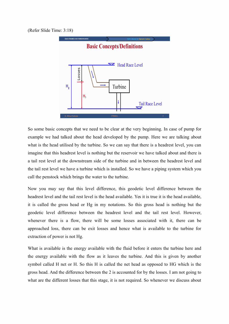
Now we will talk about each of these components in some detail, particularly the nozzle and
the spear and the bucket which we can say are like the main components in case of a Pelton
turbine. So first we will start with nozzle and spear. In a cartoon form, in a schematic form
this is a nozzle, the nozzle exits here and the jet comes out, I have intentionally shown it in an
exaggerated way, this is the portion which had the least diameter, the vena contractor and of
course there is a remaining portion of the pen stock. Now we have a spear which is kept
inside the nozzle.
This spear can move, it can go and try to close the nozzle or it can open further, this
reciprocating motion, if required, if the positioning of the spear inside the nozzle, that is if it
is retracted fully or brought in fully kept somewhere in between, this dictates what will be the
volume flow rate. So we can say that this volume flow rate happens because of the location of
the spear and of course the head available today turbine. But why do we need such an
arrangement? You can say that making the spear will be more expensive. We could have
always done this work with the help of some simple valves.
For example in our home when we want to control the water coming out in a tap, the tap itself
is a valve, we are trying to close it, open it as we wish. So why do we need it? The reason is
because we want minimum loss in this nozzle and hence what we want is the minimum
restrictions in terms of the flow rate that is possible without incurring major loss. And hence
the spear is an essential component, you cannot use any valves. And we can define few
diameters, D0 is a nominal diameter of the nozzle exit and DJ is the diameter of the jet or jet
diameter and more often than not we will use this jet diameter DJ than D0.
And typical angle for nozzle is the 2 beta is the angle of the nozzle, we have used is 84
degrees and typical angle for the spear is 50 to 60 degrees. We are now going to talk more
about the nozzle and the jet diameter.

(Refer Slide Time: 17:09)
We can say that the volume that is coming out in the form of jet is given by V dot which is
pie by 4 DJ square, that is the jet diameter, the area corresponding to the jet diameter
multiplied by CJ. And what is CJ, CJ is nothing but some constant times in root 2 GH. How
do you visualize the root 2 GH, you have studied in fluid dynamics that if we have a tank and
we have water coming out of the tank, then what is the velocity that you get? The velocity is
obtained by the change of potential energy. So the kinetic energy is obtained by the change of
potential energy and hence velocity will be nothing but root 2 GH.
So the jet is coming out in atmospheric condition because of the head imposed on the turbine
which is capital H. And hence the velocity should be proportional to root 2 GH. But why is it
KN, KN is called the nozzle velocity coefficient which varies from 0.98 to 0.99. What does it
show, that it is almost like an idealised state of 1. CJ would have been root 2 GH if there is no
loss anywhere but because of very minimal loss, we find that KN is close to 1, not exactly
one. And we can write the DJ is equal to under root 4V dot by pie KN under root 2 GH. So
this is obtained from the relationship between V dot and CJ given earlier.
We can in the same way right in the nominal diameter of the nozzle, in terms of the volume
flow rate and a nozzle coefficient which is K C0 which is magnitude of 0.81 to 0.83. So these
are the more important diameters as far as the jet is concerned. Now this jet will hit the
runner. So what will happen is this impact will now cause these motions, the momentum
change will take place and will cause the motion. Let us now look at what happened there.

(Refer Slide Time: 19:28)
When we talk about the specific speed, we have to also keep in mind the usual definition of
the specific speed, we have given N under root PC by H to the power 5 by 4. We have the
usual definition, so N is in RPM, PC is in metric horsepower or for the time being we can say
it is close to kilowatt and H is in metres. In case of multiple jets, in Pelton turbine I have
shown you the example where there is only one jet, if there are multiple jets come up to 6 jets
are possible, these jets can hit the Pelton turbine bucket from 6 different locations and in this
case the power output will be more and we can say that NSJ is nothing but, J is the number of
jets, so is nothing but N under root J times PC whole divided by H to the power 5 by 4.
And hence we can say that if there are J number of jets, then NSJ is under root times NS, this
is the relationship we have to use. Why is it important because you saw that in case of Pelton
turbine, the Pelton turbine can work between 10 to 35 and we have also seen that Francis
turbine works in the range of 60 and above. Now you may come across a situation where the
specific speed lies between 35 and 60. So what will you do? You can use multiple jets and try
to accommodate that specific speed requirement.
So you see that even if I say that the specific speed of an individual, one jet Pelton turbine is
35, if you have 4 jets, then under of 4 will give you 2, you are going close to 70. So you are
actually bridging the gap between 35 to 60. So that is where many times the multiple jets are
used but there is a restriction that you cannot go more than 6 from the practical
considerations. So this is an important aspect about the jet, the choice of jets or number of
nozzles you need to produce the power.

(Refer Slide Time: 21:54)
Now we want to talk about the Pelton wheel diameter or Pelton wheel runner. So this is my
schematic of the jet hitting a Pelton bucket, in the next slide we will talk more about the
bucket, so this hits the bucket and as a result of the momentum change we will find that there
is a net rotation is taking place in the nation shown by the arrow. This D is called the pitch
circle diameter. This is where these Pelton buckets are connected with the runner or the
wheel. Many times it is called the Pelton wheel. So on the, in the wheel you have to connect
or fasten these buckets.
Now we can say that if the rotational RPM is N, then U is nothing but pie ND by 60. Now
what causes this rotation? It is a jet which is impinging on the buckets. So that means in a
way it is related with the net head which is available for this turbine and hence we can say
that U is equal to KU times under root 2 GH and we can say that KU is blade speed ratio
which varies between 0.44 to 0.46. And hence we can find out the diameter or the pitch circle
diameter D as 60 KU times under root 2 GH by pie N.

(Refer Slide Time: 23:19)
Working speed of a turbine depends on the nature of the driven unit. If an electrical generator
has to be connected, we are directly coupling to the turbine, then what happens, we should
know that the frequency of the operations in case of let us say alternator in India is 50 hertz,
so this frequency has to be matched because we are sending the power back to the grid. And
hence we cannot have any arbitrary speed and the rotational speed is given by 120 F by P
square P is the number of poles of the magnet that we have in the alternator.
So this has to be kept in mind. The another thing that is very important from the design
perspective of a Pelton turbine is the jet ratio. This jet ratio which is often given by the
symbol N is given as the mean diameter of the runner or the pitch circle diameter of the
runner capital D divided by the least diameter of the jet or so-called the jet diameter DJ.
Typically for a good or ideal design of a Pelton turbine, this value of N should lie between 11
and 14. This is more from the design perspective but it is good to know these quantities
because this is what characterises a Pelton turbine.

(Refer Slide Time: 24:40)
The next or the most important component perhaps is this bucket. Now this bucket is shown,
I will also show you a small model bucket which is not really used for power generation but it
is more for classroom demonstrations and for demonstrations like I am going to do now. Let
us look at these buckets first before we continue this discussion.
(Refer Slide Time: 25:05)


Imagine that this is my finger is the point where this bucket is fastened to the wheel and the
water jet is coming and hitting the bucket, as a result the water comes here, this has a very
sharp edge, you can see this very sharp edge, this is called the splitter edge. As the name
suggests, this splits the jet into 2 halves, it goes here, one part of the jet comes out like this,
the other part of the jet comes out like this. So as a result of the momentum change we get
and from angular momentum conservation, we find the torque and this entire system will
move.
As this jet hits this bucket and the bucket moves, the next bucket comes from top because the
wheel as I have shown you has multiple buckets. You can also find out how many buckets are
required but that I will not discuss in today’s lecture. So you see that as the bucket comes
here, it hits, it goes and the next bucket comes and hits. It is done in such a way that we do
not waste the water. So this is called the splitter edge and we have 2 cuplike structures which
I will discuss with the PowerPoint slides, I am presenting a more detail now.
So if you want to compare the picture that you see on the slide with this one, then it should be
viewed in this fashion. You can see the view which is shown and I am taking a section XX as
shown on the slide and let us look at this section XX in some more detail.

(Refer Slide Time: 27:00)
So coming back to the slide we see that the bucket, the splitter edge is also visible now you
can imagine a line joining here is the splitter edge and you are taking a section XX and
viewing this section. You see that this is a splitter edge which is a very sharp one and as the
name suggests, this splits water, I will show you some schematic of the water being split and
this water will go and leave in this fashion. This beta 1 is the exit angle. So let us look at it
slightly more carefully with the schematics.
(Refer Slide Time: 27:37)
So this is the same section which I showed you in the last slide and I have just taken the
outline of it. This angle between the, which is tangent to these 2 curves is called the splitter

angle 2 beta S, beta S is a splitter angle and 2 beta S is the total splitter angle, because of
symmetry it is 2 beta S. So waterjet comes from the right, it hits the splitter edge, it goes
round the blade as I told you, as I showed you and then it comes out. So now think about the
flow direction in the absence of any turbine blade, any Pelton turbine bucket. This is the flow
direction, had there been no bucket, the flow would have continued undisturbed.
Now because of the presence of the bucket the flow leaves at an angle beta 1 and hence there
is a reflection Delta and you can see this Delta is very large, quite close to 180 degree. Let us
digress from Pelton turbine and look back what you are studied in fluid dynamics portion of
this course. You have done momentum conservation and you perhaps have also studied that
you have plate which is C type, which is just imagine only this portion of the plate is there, it
is not a Pelton turbine bucket, it is just a plate, then the flow comes here and leaves by 180
degree.
Why we have that 180 degree, you have done the problems to show that it has a maximum
momentum transfer and the maximum force. Now that maximum force will give rise to the
maximum torque. So this kind of C structure for this blade is desirable when we are trying to
generate a maximum force because of the change in direction. There is no change in pressure,
I repeat, this is an impulse turbine, this bucket is in atmospheric condition, so there is no
change in pressure. What causes this force is simply the direction change. And hence ideally
it should have been 180 degree.
Now in the real configuration 180 degree is not possible because as I told you that there is not
just one bucket, there are many buckets which are arranged on the Pelton wheel. Now as one
bucket is hit by the jet, it moves, the neighbouring bucket comes in. So if this deflected jet
has to go back, it will hit the neighbouring jet which is not desirable. And hence we have a
deflection angle Delta which is quite close to 180 degree but not 180 degree. Actually the
value will be between 165 to 170 degrees. And the other angle is the splitter edge.
When we have the splitter edge, we actually have typically between 7 degrees and 15
degrees. But many times we may solve the problem, many times we may do the first cut
design assuming that these are actually not having any angle between the axis in the direction
of the jet and the plates deviations. So we can say that if no information is given, if any
problem you have to solve, then you can take beta S to be zero. So you understand… but now
you may say why do I need 2 of these C split structures, why do not we have a Pelton bucket

which is simpler to make with just one half because that itself gives me a large turning angle
of Delta and I will get a large force?
This is because we are also trying to balance the normal force. So you see that initially the jet
is coming in the horizontal direction, when it leaves, it leaves with 2 components, one along
horizontal, one along the normal. So that means if we are thinking in terms of forces, we will
experience FX as well as FY. Now this force which is tangential is actually desirable because
the tangential force gives rise to the torque, but the normal force is not desirable. And hence
if we have a symmetric structure here, then it will balance or neutralise this Fx here by the Fx
at the bottom.
And hence we may not have any significant normal thrust. And this splitter actually ensures
that the deviation or the flow is turning around in both directions properly. So this is why this
structure however complicated it looks is very important and hence the bucket design is a
very important part for the Pelton turbine design. Okay. Let us continue with the discussion
further because we have to construct the velocity triangle.
(Refer Slide Time: 32:42)
The reason why I am trying to explain these things slowly is because unlike the Francis and
Kaplan turbines which will talk in the next class, Pelton turbine is structurally slightly
different. So let us start again with the water jet hitting the bucket and this is the pitch circle
diameter as we have said, the direction of rotation is also given. So if we look at this portion
more carefully, we can say that if we view it, this is the Pelton turbine bucket, this is the
splitter edge and this water is jet is coming.

Essentially we are looking from this side and once it comes, if we construct a plane, then we
can see that the water will come and leave like this. And that gives rise to these dotted lines.
So now when I look at these dotted lines more carefully, I get the shape of the bucket and you
see that U is the velocity, the rotational velocity, W2 and C2 are our usual definitions of
relative velocity and absolute velocity respectively and we are talking about 2 as a subscript
means this is the high pressure side, the inlet for these turbines.
And we see that this is leaving, flow is leaving, this is W1 tangentially and of course U does
not change, we are talking about U based on this diameter and this small height difference is
negligible and hence let the U1 equal to U2 and we are talking about the absolute velocities.
(Refer Slide Time: 34:22)
So looking at the velocity triangles now more closely, we can bring the cartoon of the Pelton
bucket and look at it at the pressure side as well as at the suction side. So our usual symbols
of U, C2 and W2 is given. So if you see the flow comes like this and leaves, so the axe, angle
between this axis and this direction is half of this 2 beta S or it is beta S. And hence from our
definition of beta 2, this is nothing but 180 degree - beta S. So this has to be borne in mind. If
in some problems or in some designs you do not want beta S, then beta 2 is 180 degree, that
we will talk about later on.
So right now we are talking about the generalised case. That is we have a beta S which is
non-zero. Similarly we can talk about the exit or the outlet of the blade and the flow leaves
tangentially which is given here by W1 and we have beta 1 and Alpha 1. And if there is no
friction, since the pressure has to be, that, we get W 1 equal to W2. However friction may

also be present and in that case the friction will reduce the relative velocity and we have W
ones K times W2 where K is less than one. So depending on what is given in the problem you
may choose W1 equal to W2 but this specifically it is given that the friction is reducing the
velocity and we have a factor of K, then that has to be accommodated.
And in that case also please note that this relative velocity is, whether it is W 1 equal to W2
or W1 equal to K W2, the pressure is still atmospheric and there is no change in static
pressure. So I repeat, if nothing is mentioned, choose frictionless flow, that is K equal to 1.
Now we will talk about the specific work W BL and also the power.
(Refer Slide Time: 36:31)
So we say that come into specific work and power we can say that W BL is equal to U C2U -
C1U, why is that because U1 equal to U2 equal to U. And we can write C2U in terms of U -
W2U or U - W2 cos beta 2. Please keep the velocity triangle in mind. And we can further say
from the exit velocity triangle that C1 U is nothing but U - W1 U which is U - W1 cos beta 1.
And now we can relate W1 and W2, like W1 is K times W2 and we can take W2 out and we
can write W BL equal to U W2 times - cos beta 2+ W1 is replaced as K times W W2 and
hence K remains K times cos beta 1.
Of course it is possible that we may have to do some simplifications and if we say that beta S
is equal to 0, then what happens to beta 2, beta 2 is nothing but 180 degree and this triangle
which you have seen at the inlet degenerates into a straight line. So we will have C2U and
W2 all along one line and we say that W2 is nothing but C2 - U. I may also add here that this
C2 is nothing but the jet velocity which is CJ. The jet velocity that comes out of the nozzle,
we assume that the same velocity reaches the Pelton turbine bucket and hence C2 equal to CJ.
So we can say that in such a scenario where beta S is equal to 0, we get WBL equal to U
times C2 - U times multiplied by 1+ K times cos beta 1 because cause beta 2 is equal to 1.
And W2 has now been simply replaced as C2 - U. We can get from this relationship for the
special case, I am writing now for the special case what is the power but you can do the same
thing for the generalised case without any harm. So we can say that coupling power is rho V
dot W BL which for the special case of beta S equal to 0 comes down to rho V dot U times
C2 - U times 1+ K cos beta1.
Now this result is interesting. We find that the power will be maximum when the jet velocity
CJ or C2 is equal to twice U and the power will be 0 when CJ is equal to U. This is very
important, why, because we are now talking about, see the first case is trivially true that when
U equal to 0, that is the runner is not rotating, then there is no question of power generation.
However, even if runner is rotating, you may end up in a scenario when there is no power,
when does that happen, when C2 or CJ, that is the jet velocity is equal to the bucket speed.
And this is called the runaway speed. What is runaway speed? In a simple English if I say
runaway, that means something is running away. So imagine that the nozzle is human being,
nozzle is sending jet of water and hitting the bucket and the bucket is also another human
being, let us say you and your friend. Now when this, there is a gap between the nozzle exit
and the bucket, now if the jet has a higher velocity, so even if the bucket is trying to run away,
is trying to move away, it will hit the bucket.
But when the limit comes, when the jet velocity is equal to the bucket rotational speed, then
what happens, the bucket is not going to be hit, so there is no contact. So we are talking about
the runaway speed and that is not desirable. So when there is no load, we are talking about
the speed going to runaway speed and that brings us to the important question of how we can
regulate the flow. So you understand we are talking about the power, this power will be
maximum when the jet velocity is twice the rotational speed, you can do this calculation
yourself and prove that what I am saying makes sense.

(Refer Slide Time: 41:26)
And power will be zero is trivially true when U equal to 0 and when C 2 equal to U, this
bracketed them goes to 0. Before I go into the regulation of Pelton turbine, let us talk about
the need. Let us say we do not want the turbine to go for to the runaway speed and there is a
scenario when there is no power extraction, so power is zero, it is tripped, so we have to
somehow stop the turbine. You may say what is the problem, I will just bring the spear and
block the nozzle.
Even if I assume that you have a mechanism by which instantaneously you can bring the
spear and block the nozzle, it is not desirable from the hydrodynamic point of view. You will
end up getting what is known as a fluid transient phenomenon of water hammer. How do I
visualize water hammer? Imagine that we all are fluid particles and in that fluid particles we
are going from the penstock through the nozzle we are issuing out as a jet. And suddenly this
spear comes and instantaneously block the nozzle exit. In that case what happens?
I if I am a fluid particle, I will see that the suddenly the road is blocked but I want to escape,
so then I will turn back and in this process the gap between the 2 fluid particles, let us say
between you and me, it reduces. So there is a compression wave and then we try to escape
from the other route, that is up the penstock. And then we find that we cannot go that path
and then we reflect back. So this creates what is known as a compression and rarefaction
waves and the fluid in this case the liquid actually behaves as a compressible flow.
So this gives rise to a very high pressure in the piping system and the piping system gets
damaged. So water hammer pressure or the fluid transient phenomenon called water hammer

has to be avoided. And hence even if it is possible theoretical into during the spear and block
the water instantaneously, it is not desirable. So what we can do alternately? We can say that
we can bring a deflector, this deflector in a normal position is open which allows the jet to go
unhindered and hit the bucket.
When it is required, when we want to stop the turbine, 2 things can be done, one is we can
use the brake nozzle, do you remember the brake nozzle? We talked about the brake nozzle
which actually acts on the opposite side of the bucket and tries to slowdown. So we can
engage the brake nozzles when we are trying to slowdown the turbine and simultaneously
engage this deflector. As the name suggests the deflector actually deflects the fluid. And when
it deflects the fluid, the jet comes out of the nozzle, very true but it does not go straight and
hit the bucket, it gets reflected and falls.
And then we have enough time to bring the spear slowly and close it, so that water hammer
pressure does not take place. And hence the regulation of Pelton turbine is done when we are
talking about the flow regulation. This brings us to an end of this discussion on Pelton
turbine, of course we will take up some problems when we do the tutorials to do get the
mathematics correctly.
(Refer Slide Time: 45:12)
So now we to summarise that we have talked about the definition of net head, we have also
talked about the classifications of the turbines based on different yardsticks direction of flow,
impulse reaction but most importantly based on the specific speed. We have talked about the
structure and components of Pelton turbine and we have also talked about the flow regulation

which is required. With this I conclude the discussion on Pelton turbine, we will continue the
discussion on hydraulic turbine in the next lecture when we talk about the reaction turbines,
namely Francis and Kaplan turbine. And there we will also introduce the concept of the
structure called draft tube. Thank you.