Embed Size (px)
Citation preview
The 19th International Symposium on Transport Phenomena, 17-20 August, 2008, Reykjavik, ICELAND
FLUID FLOW AND HEAT TRANSFER WITHIN AND AROUND A POROUS IRON ORE PELLET PLACED IN INFINITE SPACE
A-L. Ljung1, T.S. Lundström1 and K. Tano2
1 Division of Fluid Mechanics Luleå University of Technology, Luleå, Sweden
2 LKAB, Research and Development Malmberget, Sweden
ABSTRACT The forced convective heating of a porous cylinder with properties similar to an iron ore pellet is here numerically investigated. The numerical setup is based on a two dimensional microporous model with surrounding flow field taken into account. The simulations are carried out with special attention directed towards minimizing numerical errors. With interface conditions provided by CFD, simulations show an increased heat transfer rate for the porous cylinder when compared to a solid. INTRODUCTION Iron ore pellets are one of the most refined products for mining industry. Being such, there is a natural driving force to enhance the pelletization in order to optimize production and improve quality since the process is both time and energy consuming. A traveling grate pelletizing plant consists of four stages: drying zone, pre-heat zone, firing zone and a cooling zone. Throughout the process, pellets are transported as a continuous bed on rosters while warm air is convected through the bed from either above or below. The dominating heat transfer mechanism in thus forced convection; over 90% of the heat is transferred this way (Meyer, 1980). Before entering the drying zone, grained ore, binders and water are formed to green balls with an average diameter of around 12 mm. The average particle size of the grained ore is ≈ 26 μm (Forsmo, 2007). For a continuous development of this process, a long term goal has been established to develop tools and techniques with which the drying zone can be optimized. In order to be successful in this progression it is of highest importance that the process is known in detail. Following the work of Ljung et al. (2006) and Ljung et al. (2008), heat and fluid transport around and within a single pellet placed in infinite space is here modeled with aid of Computational Fluid Dynamics. The numerical model is applied on a cylindrical geometry representing a two dimensional pellet. Flow around and within a porous cylinder has several fields of applications, for example in various gas-solid reactors applied in chemical and biological processes. To examine this phenomenon, Noymer (1998), conducted a general investigation of how moderate Reynolds number and permeability influence the drag on a permeable cylinder. Von Wolfersdorf (2000) presented a mathematical model for invicid and incompressible flow past a porous cylinder. A numerical investigation of flow through and around a permeable cylinder subjected to flows at relatively low Reynolds
numbers was presented by Bhattacharyya et al. (2006), where the influence of Darcy number on drag and separation angle was investigated. The flow past and within a permeable spheroid was investigated by Vainshtein (2002). Regarding heat transfer within a porous material, particle to fluid heat transfer in a packed bed has been soundly examined by Amiri (1994), Wakao et al. (1979) and Nield (1999). They have all adopted a method where the heat is calculated by two energy equations and a particle to fluid heat transfer coefficient for the exchange of energy between the two phases. Heat transfer between a solid cylinder and its surrounding has been extensively studied by Zukauskas et al. (1985) and Incropera et al. (2007). The combination of heat distribution and fluid motion through a porous cylinder has experimentally been examined by Nomura (1985), where the influence of mass transfer of vapor on heat transfer also was investigated. The aim with this work is to numerically study the heat transfer within and around a porous cylinder. Flow at low Re is considered in this paper but the developed model will be applicable to higher Re as well.
D
D The resulting model is compared to heating of a solid cylinder and will lay ground to future model development where drying of a porous pellet is considered. THEORY The governing equations are here described for the transport of fluids within as well as around the porous pellet. Continuity equations Continuity for respective phase must hold according to (Kundu, 2002),
( ) 0=⋅∇+ uρ∂∂ρ
t. (1)
Momentum equations The momentum equations are in their turn expressed differently outside and inside the pellet in order to facilitate the computations. Hence, the flow of air outside the pellet is described by the following form of the momentum equation
uu 2∇+−∇= μ∂∂ρ p
t. (2)
In order to describe the transport of air through the porous pellets, a momentum equation porous medium
The 19th International Symposium on Transport Phenomena, 17-20 August, 2008, Reykjavik, ICELAND
analogue to the Navier-Stokes equation is used, which there are various forms of. To exemplify, the commonly used Darcy's law is in refined, one dimensional form expressed as (Bear, 1988)
AQ
Kdxdp μ
−= . (3)
The coefficient K, called permeability in single phase flow, is independent of the nature of the fluid and is exclusively given by the geometry of the medium. Darcy’s law is valid as long as Reynolds Number based on average grain diameter (Red) does not exceed some value, often between 1 and 10. To couple the flow through the porous medium to the surrounding flow, it is necessarily to use an equation with both linear and quadratic velocity coefficients. An equation that offers this is the Ergun equation (Ergun, 1952),
( ) ( )dU
dU
yp 2
323
2 175.11150 ρεεμ
εε −
+−
=Δ . (4)
The Ergun equation quite often fits data well over the entire range of Red, and will provide similar results as Eq. (3) for low Red. Energy equations The energy equation describing temperature distribution of the flow outside the cylinder is given by
( ) ( ) ( )iffffffp
ffp TTc
tT
c φαρρ +∇⋅∇=∇⋅+∂∂
u . (5)
For the solid and gas temperature inside the porous medium two energy equations are used according to (Nield, 1999)
( ) ( ) ( ) ffffffpf
fp TTct
Tc φεαρρε +∇⋅∇=∇⋅+
∂
∂u (6)
( )( ) ( )( ssss
sp T )t
Tc φαερε +∇−⋅∇=∂∂
− 11 . (7)
The interstitial fluid to particle heat transfer is attained by adding a source and a sink in the following manner
)( fssfsff TTha −=φ (8)
)( sfsfsfs TTha −=φ . (9)
The particle to fluid heat transfer coefficient, hsf, is an experimentally determined parameter whose value depends on all variables influencing convection such as the surface geometry, the nature of fluid motion, the properties of the fluid and the bulk fluid velocities (Incropera et al., 2007). There are various proposed values for this coefficient (Wakao et al, 1979; Kuwahara et al., 2001; Kunii et al., 1961). Kuwahara proposed a value according to
( ) ( ) 3/16.02/1 PrRe121141 d
f
sf
kdh
εεε
−+⎟⎠⎞
⎜⎝⎛ −+= , (10)
yielding a nearly constant value of Nud (Nud = hsfd/kf) for small Red. The specific surface area, asf, is developed from geometrical considerations (Amiri, 1994) and stated by
psf D
a )1(6 ε−= . (11)
Interface Conditions The convective heat transfer coefficient at the interface between the porous and fluid region is estimated to be of the same magnitude as that of a solid cylinder due to the small particle size, and is thus calculated from (Incropera et al., 2007; Kaya, 2007)
∞−
∂∂−=
TTnTk
hs
sf (12)
where s is a point along the surface and n is the normal to the surface. Following this, the total loss of heat from the surrounding airflow is given by the sink
)( ∞−= TThA sfiφ (13)
at the interface. This is in agreement with theory in the work of Nomura (1985). Surface roughness is here neglected due to the small particle size. The corresponding solid energy source Φsi on the interface can be estimated with
)( ss TThAi
−= ∞φ (14)
since the contact area inside the medium will be dominating when compared to the surface contact area. The heat contribution supplied by the surrounding air could as well be shared by the solid and gas inside the porous medium. Such an approach was also tested yielding the same result as with the method proposed in Eq. (14) due to the extensive interstitial heat transfer. MODELING The numerical model is subjected to the following conditions:
- Based on the properties of grained ore, the model porous cylinder is built up by spherical particles with a diameter of 26 μm.
- Since over 90% of the heat between the phases is transferred by convection in a traveling grate pelletizing plant, all other heat transfer mechanisms between the phases are excluded (Meyer, 1980).
- In the real pelletization process, the inlet air temperature in the drying stage is approximately 300 ºC and the initial temperature of the bed about 35 ºC. Using the fact that the model outlined above represents pellets with an arbitrary position in the bed, the pellet is placed where the temperature is 150 ºC for all simulations.

The 19th International Symposium on Transport Phenomena, 17-20 August, 2008, Reykjavik, ICELAND
- To facilitate verification and validation, the inlet velocity is set to 0.037 m/s, corresponding to a flow with ReD ≈ 23.5. An average static pressure with a relative pressure set to zero is used at the outlet boundary.
The material parameters of iron ore and the estimated properties of the porous material used are presented in Table 1).
Table 1. Properties of magnetite (at approx. 20 C) and
geometrical estimates. Parameter Value Reference Density [kg m-3]
5175 (Waples, 2004)
Thermal conductivity [cal cm-1 sec-1 oC-1]
12.6e-3
(Clark, 1966)
Specific heat capacity [J kg-1 K-1]
586
(Waples, 2004)
Porosity 0.315 (Forsmo, 2007)
Pellet diameter [m]
0.012
(Forsmo, 2007)
Average particle size of raw material [m]
26e-6
(Forsmo, 2007)
NUMERICAL METHOD The solution domain is subdivided into a finite number of contiguous control volumes (CV) and the conservation equations are applied to each CV in such way that relevant quantities (mass, energy etc) are conserved. The simulations are carried out with the commercial software ANSYS CFX 11.0. For the discretization of the advection term the Numerical Advection Correction Scheme (NACS) is used with blend factor β set to one for the transport equations. The robust, implicit and unbounded Second Order Backward Euler (SOBE) scheme is used for time discretization and shape functions approximate the pressure gradient and diffusion terms (ANSYS). NUMERICAL ACCURACY Numerical solutions for fluid flow problems have various types of unavoidable errors, mainly modeling errors, discretization errors and iteration errors. A grid convergence test based on results from simulations of three consecutive grids is carried out in order to estimate the magnitude of the discretization error. The transient simulations of heat transfer between a solid cylinder and surrounding flow field are compared after a total time of 3 s. The temperature at the upstream stagnation point is chosen as key variable and is used for the error analysis.
Table 2. Temperatures at upstream stagnation point. Grid No. Number of nodes Temperature
[K] 1 432790 308.595 2 338686 308.596 3 265250 308.597
The results of the grid refinement study show monotone convergence, see Table 2). The polynomial curve in
Fig. 1 indicates that the results are in the asymptotic range and an extrapolated value for an infinitely fine mesh is thus obtained.
0 0.5 1 1.5 2
308.59
308.595
308.6
308.605
308.61
Normalized number of nodes
Tem
pera
ture
[K]
y = - 0.0012229*x2 + 0.0063847*x + 308.59
Fig. 1. Plot of temperature at the upstream stagnation point as function of normalized number of nodes. From this assessment it can be concluded that grid no. 3 has a relative error of only 2 per mil. This mesh is therefore used in all further simulations. The mesh resolution at the interface is displayed in Fig. 2. The figure also displays the two points that will be used to evaluate the results; Point 1 is located at the upstream stagnation point and Point 2 at the centre of the cylinder.
Fig. 2. Mesh resolution close to and within the cylinder also indicating the two evaluation points. RESULTS AND DISCUSSION To ensure credibility of the result, all steps toward the complete porous model are evaluated. To start with, the fluid flow past a solid and porous cylinder is investigated. Fluid flow past a cylinder The flow fields around a solid and porous cylinder with data according to Table 1) are practically the same, see Fig. 3 and 4, respectively.

The 19th International Symposium on Transport Phenomena, 17-20 August, 2008, Reykjavik, ICELAND
Fig. 3. Velocity streamlines for flow around a solid cylinder.
Fig. 4. Velocity streamlines for flow around and through a
porous cylinder.
Regarding the flow inside the porous medium, the velocity profile at x = 0 (center of cylinder) as function of location y is displayed in figure 5.
1.5 2 2.5 3 3.5
x 10-9
-6
-4
-2
0
2
4
6x 10
-3
y [m
]
Velocity [m/s] Fig. 5. Velocity profile at the center of the porous cylinder.
The results are in agreement with the work of Bhattacharyya et al. (2006), where it is shown that flow around the porous cylinder with porosity as large as ε = 0.629 behaves as if the cylinder was impermeable, as compared to the porosity ε = 0.315 used in this work. The size of the wakes downstream of the cylinders is representative for the corresponding ReD, when compared to experimental visualization (Van Dyke, 1982).
Heat transfer through a cylinder All simulations with heat transfer are subjected to the same initial condition, namely that the cylinder is placed in a free stream with temperature T = 150 °C at time t = 0. First, heating of a solid cylinder is examined. The temperature fields of the surrounding air and the solid material after 10 s of heating is in accordance of what can be expected as displayed in Fig. 6. This implies that the heating of the model pellet is strongly dependent on the direction of the flow.
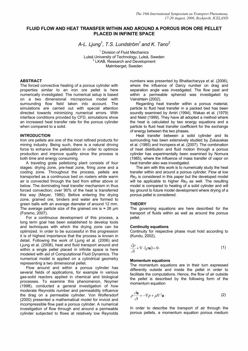
Fig. 6. Temperature of surrounding air flow with corresponding solid temperature at t = 10 s. In order to get quantitative comparisons, the local NuD is calculated from Eq. (12) using temperature gradients available from simulation. The maximum value achieved, NuD = 4.93 at the upstream stagnation point where θ = 0 (see Fig. 7), is in good agreement with Incropera et al. (2007) who proposed a value of NuD of 4.96 at this point for a solid cylinder (for low ReD). Notice that the simulation presented has a corresponding relative error of 6 per mil.
The 19th International Symposium on Transport Phenomena, 17-20 August, 2008, Reykjavik, ICELAND
0 pi/2 pi 3*pi/2 2*pi1
1.5
2
2.5
3
3.5
4
4.5
5N
u=hD
/k
θ [rad] Fig. 7. Local NuD as function of angle θ. θ = 0 represents the
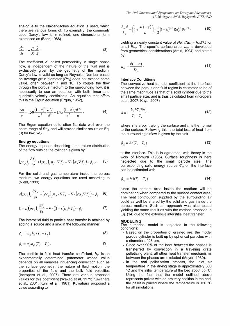
upstream stagnation point. Two steps are now performed to ensure that the porous model with NuD from the simulation of the solid model is set up correctly. First, the temperature distribution in a porous cylinder with small porosity (ε = 0.05) is evaluated and compared to a solid, since the behavior of these should be similar due to the small porosity. The result from this comparison is shown in Fig. 8.
0 2 4 6 8 10
308.5
309
309.5
310
310.5
311
Tem
pera
ture
[K]
Time [s]
Solid, Point 1Solid, Point 2Porous, ε = 0.05, Point 1Porous, ε = 0.05, Point 2
Fig. 8. Comparison between a permeable cylinder with ε = 0.05 and a solid cylinder at Point 1 and Point 2. Since the porous medium has a lower conductivity (Zabbarov, 1967) leading to a greater surface temperature, the temperature at Point 1 should be slightly larger for the porous cylinder. This is verified in Fig. 8 at t = 10 s. The same theory applies to Point 2, where the temperature of the porous material instead should be somewhat smaller, depending on the chosen porosity. The discrepancy of surface temperatures at the first few seconds of the simulation originates from the numerical set-up where the surface temperature of the solid cylinder is 150 °C at t = 0. During the calculations there is also a discrepancy in Nu between the solid and porous cylinder the first three seconds, before the flow have stabilized. The reason to this is that for the solid cylinder the value of Nu increases to a final value during the initial stage while this final Nu is used for all time steps for the porous cylinder. Hence the heat transfer to the porous cylinder is too high in the beginning, eventually leading to a higher temperature.
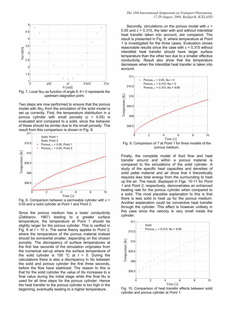
Secondly, simulations on the porous model with ε = 0.05 and ε = 0.315, the later with and without interstitial heat transfer taken into account, are compared. The result is presented in Fig. 9, where temperature at Point 1 is investigated for the three cases. Evaluation shows reasonable results since the case with ε = 0.315 without interstitial heat transfer should have larger surface temperature than the other two due to a smaller effective conductivity. Result also show that the temperature decreases when the interstitial heat transfer is taken into account.
0 2 4 6 8 10
308.5
309
309.5
310
310.5
311
Tem
pera
ture
[K]
Time [s]
Porous, ε = 0.05, Nu = 0Porous, ε = 0.315, Nu = 0Porous, ε = 0.315, Nu = 9.69
Fig. 9. Comparison of T at Point 1 for three models of the
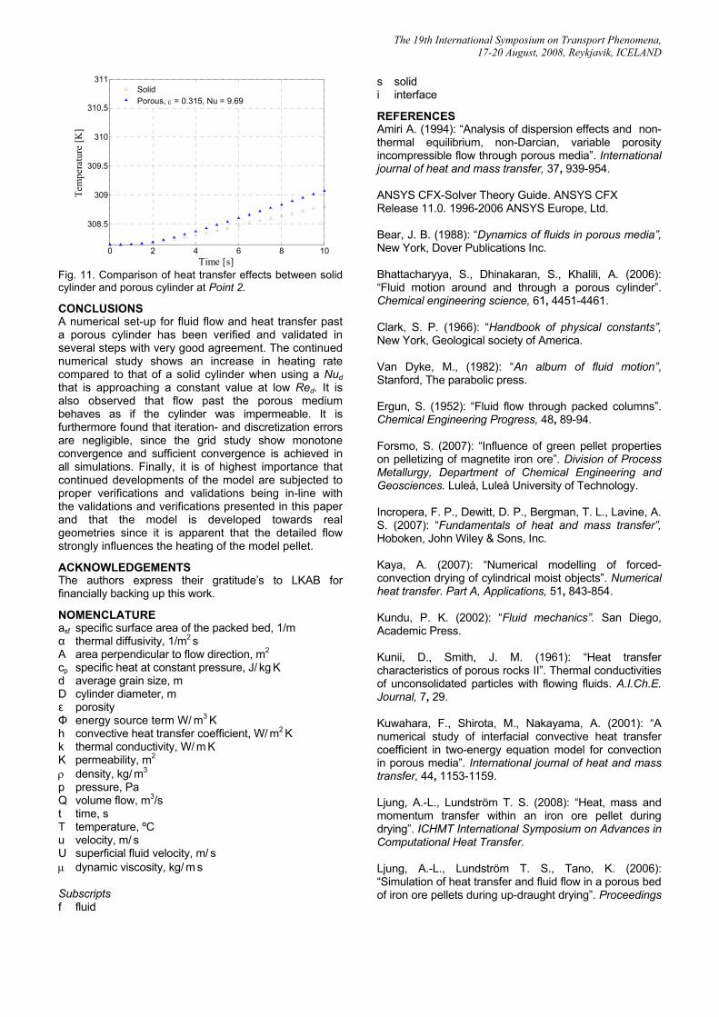
porous medium. Finally, the complete model of fluid flow and heat transfer around and within a porous material is compared to the simulations of the solid cylinder. A study of the specific heat capacities and densities of solid pellet material and air show that it theoretically requires less total energy from the surrounding to heat up the air. The result, displayed in Figs. 10-11 for Point 1 and Point 2, respectively, demonstrates an enhanced heating rate for the porous cylinder when compared to a solid. The most plausible explanation to this is that there is less solid to heat up for the porous medium. Another explanation could be convective heat transfer through the cylinder. This effect is however unlikely in this case since the velocity is very small inside the cylinder.
0 2 4 6 8 10
308.5
309
309.5
310
310.5
311
Tem
pera
ture
[K]
Time [s]
SolidPorous, ε = 0.315, Nu = 9.69
Fig. 10. Comparison of heat transfer effects between solid cylinder and porous cylinder at Point 1.
The 19th International Symposium on Transport Phenomena, 17-20 August, 2008, Reykjavik, ICELAND
0 2 4 6 8 10
308.5
309
309.5
310
310.5
311Te
mpe
ratu
re [K
]
Time [s]
SolidPorous, ε = 0.315, Nu = 9.69
Fig. 11. Comparison of heat transfer effects between solid cylinder and porous cylinder at Point 2. CONCLUSIONS A numerical set-up for fluid flow and heat transfer past a porous cylinder has been verified and validated in several steps with very good agreement. The continued numerical study shows an increase in heating rate compared to that of a solid cylinder when using a Nud that is approaching a constant value at low Red. It is also observed that flow past the porous medium behaves as if the cylinder was impermeable. It is furthermore found that iteration- and discretization errors are negligible, since the grid study show monotone convergence and sufficient convergence is achieved in all simulations. Finally, it is of highest importance that continued developments of the model are subjected to proper verifications and validations being in-line with the validations and verifications presented in this paper and that the model is developed towards real geometries since it is apparent that the detailed flow strongly influences the heating of the model pellet. ACKNOWLEDGEMENTS The authors express their gratitude’s to LKAB for financially backing up this work. NOMENCLATURE asf specific surface area of the packed bed, 1/m α thermal diffusivity, 1/m2 s A area perpendicular to flow direction, m2
cp specific heat at constant pressure, J/ kg K d average grain size, m D cylinder diameter, m ε porosity Φ energy source term W/ m3 K h convective heat transfer coefficient, W/ m2 K k thermal conductivity, W/ m K K permeability, m2
ρ density, kg/ m3
p pressure, Pa Q volume flow, m3/s t time, s T temperature, ºC u velocity, m/ s U superficial fluid velocity, m/ s μ dynamic viscosity, kg/ m s Subscripts f fluid
s solid i interface REFERENCES Amiri A. (1994): “Analysis of dispersion effects and non-thermal equilibrium, non-Darcian, variable porosity incompressible flow through porous media”. International journal of heat and mass transfer, 37, 939-954. ANSYS CFX-Solver Theory Guide. ANSYS CFX Release 11.0. 1996-2006 ANSYS Europe, Ltd. Bear, J. B. (1988): “Dynamics of fluids in porous media”, New York, Dover Publications Inc. Bhattacharyya, S., Dhinakaran, S., Khalili, A. (2006): “Fluid motion around and through a porous cylinder”. Chemical engineering science, 61, 4451-4461. Clark, S. P. (1966): “Handbook of physical constants”, New York, Geological society of America. Van Dyke, M., (1982): “An album of fluid motion”, Stanford, The parabolic press. Ergun, S. (1952): “Fluid flow through packed columns”. Chemical Engineering Progress, 48, 89-94. Forsmo, S. (2007): “Influence of green pellet properties on pelletizing of magnetite iron ore”. Division of Process Metallurgy, Department of Chemical Engineering and Geosciences. Luleå, Luleå University of Technology. Incropera, F. P., Dewitt, D. P., Bergman, T. L., Lavine, A. S. (2007): “Fundamentals of heat and mass transfer”, Hoboken, John Wiley & Sons, Inc. Kaya, A. (2007): “Numerical modelling of forced-convection drying of cylindrical moist objects”. Numerical heat transfer. Part A, Applications, 51, 843-854. Kundu, P. K. (2002): “Fluid mechanics”. San Diego, Academic Press. Kunii, D., Smith, J. M. (1961): “Heat transfer characteristics of porous rocks II”. Thermal conductivities of unconsolidated particles with flowing fluids. A.I.Ch.E. Journal, 7, 29. Kuwahara, F., Shirota, M., Nakayama, A. (2001): “A numerical study of interfacial convective heat transfer coefficient in two-energy equation model for convection in porous media”. International journal of heat and mass transfer, 44, 1153-1159. Ljung, A.-L., Lundström T. S. (2008): “Heat, mass and momentum transfer within an iron ore pellet during drying”. ICHMT International Symposium on Advances in Computational Heat Transfer. Ljung, A.-L., Lundström T. S., Tano, K. (2006): “Simulation of heat transfer and fluid flow in a porous bed of iron ore pellets during up-draught drying”. Proceedings
The 19th International Symposium on Transport Phenomena, 17-20 August, 2008, Reykjavik, ICELAND
of the Fifth International Conference on CFD in the Process Industries. Meyer, K. (1980): “Pelletizing of Iron Ore”, Berlin, Springer-Verlag Berlin Heidelberg New York. Nield, D. A. (1999): “Convection in porous media”, New York, Springer-Verlag. Nomura, K. (1985): “Heat and mass transfer coefficients for porous horizontal cylinders”. American Institute of Chemical Engineers. AIChE Journal, 31, 1217-1219. Noymer, P. (1998): “Drag on a permeable cylinder in steady flow at moderate Reynolds numbers”. Chemical engineering science, 53, 2859-2869. Vainshtein, P. (2002): “Creeping flow past and within a permeable spheroid”. International journal of multiphase flow, 28, 1945-1963. Wakao, N. N., Kaguei, S., Funazkri, T. (1979): “Effect of fluid dispersion coefficients on praticle-to-fluid heat
transfer coeficients in packed beds -correlation of Nusselt numbers”. Chemical engineering science, 34, 325-336. Waples, D. W. (2004): “A Review and Evaluation of Specific Heat Capacities of Rocks, Minerals, and Subsurface Fluids”. Part 1: Minerals and Nonporous Rocks. Natural Resources Research, 13, 97. Von Wolfersdorf, L. (2000): “Potential flow past a porous circular cylinder”. Zeitschrift für angewandte mathematik und mechanik, 80, 457-471. Zabbarov, R. (1967): “Effect of porosity and temperature on the thermal conductivity of cermets”. Journal of engineering physics, 13, 373-375. Zukauskas, A. Ziugzda, J. (1985): “Heat transfer of a cylinder in crossflow”. Washington, Hemisphere Publishing Corporation.