Embed Size (px)
Citation preview

Fluid Power Controls Laboratory (Copyright – Perry Li, 2004-2010)
M..E., University of Minnesota (updated 12.2010)
• Labs this week:• Lab 10: Bleed-off Circuit
• Lab 11/12: Asynchronous/Synchronous and Parallel/Tandem Operations
• Systems Review Homework (due 10/12)
• Research / internship opportunities:• CCEFP fluid power scholar program
• Participation is research lab
• Fluid Bulk modulus
• Fluid Inertance
• Component modeling• Pressure reducing valve
• Pressure compensated flow control valve
Lecture 5
119

Fluid Power Controls Laboratory (Copyright – Perry Li, 2004-2010)
M..E., University of Minnesota (updated 12.2010)
120
Fluid Compressibility: Bulk Modulus
• Hydraulic fluid is slightly compressible: • fluid volume decreases from V by dV on application of pressure dP
• is the bulk modulus -
• varies a lot with temperature and amount of aeration
• For β = 200kPsi, 5000psi pressure compresses fluid by 2.5%
• Increases with pressure
• Decreased significantly by entrained or dissolved air content
dPV
dV
β1=−
β
��
�=
��
�

Fluid Power Controls Laboratory (Copyright – Perry Li, 2004-2010)
M..E., University of Minnesota (updated 12.2010)
121
Bulk modulus: cont’’’’d
• For precise application, can be important, especially for long stroke, narrow, cylinders
• dL = pressure*L/β = force*L/(Area*β)
• D=0.5in bore, 6 in stroke • 0.15in/1000 lb-f
• D=1 in bore, L=1.5in stroke (same volume)• 0.01in/1000 lb-f
• 16 times smaller
Note that compressibility equation looks like equation for a spring

Fluid Power Controls Laboratory (Copyright – Perry Li, 2004-2010)
M..E., University of Minnesota (updated 12.2010)
Energy in Compressed Fluid (Li and Wang, 2011)
•
122
Meanbulkmodulus: WV�Pg, P0� = P�
�
2β

Fluid Power Controls Laboratory (Copyright – Perry Li, 2004-2010)
M..E., University of Minnesota (updated 12.2010)
123
Accounting for Bulk Modulus
• Compressibility increases spring like action
• Possibility of having resonance
Compressible cylinder
MSpring, K
M
Ideal cylinder (velocity generator)+ Spring
V = Q/A
QA Questions: How to pick K ?

Fluid Power Controls Laboratory (Copyright – Perry Li, 2004-2010)
M..E., University of Minnesota (updated 12.2010)
124
Modeling compressibility in cylinders
• Consider when the cylinder ports are blocked
• Suppose the load F is applied on the piston, how much does the piston move?
• Note: the chamber should include all the volumes between the piston and the valve (i.e. include hoses)
• Case 1: Double ended actuator
• Case 2: Single ended actuator
• Does the spring constant change with position of the piston?
F
Fluid Power Controls Laboratory (Copyright – Perry Li, 2004-2010)
M..E., University of Minnesota (updated 12.2010)
125
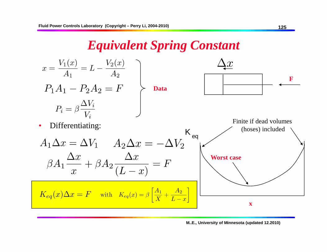
Equivalent Spring Constant
• Differentiating:
F
Data
x
Keq
Worst case
Finite if dead volumes(hoses) included

Fluid Power Controls Laboratory (Copyright – Perry Li, 2004-2010)
M..E., University of Minnesota (updated 12.2010)
126
Fluid Inertance (inertia)
• F = m * a for the accelerating fluid (transients)
• Normally, the pressure needed to accelerate the fluid is neglected.
• When is this important ?
• Momentum calculation for a hose: Length = L, Area = A
P1 P2
[ ] [ ]LQdt
dLAv
dt
dPA ρρ ==∆⋅
dt
dQ
A
LP
=∆ ρ
inertance
Important for long, narrow pipes – water hammer effect!

Fluid Power Controls Laboratory (Copyright – Perry Li, 2004-2010)
M..E., University of Minnesota (updated 12.2010)
How to make a big mass out of little mass?
• Total weight of device = M
• Kinetic energy = (100 M) v2/2
• What is in the pink box?
127
v v

Fluid Power Controls Laboratory (Copyright – Perry Li, 2004-2010)
M..E., University of Minnesota (updated 12.2010)
128
Power Computations
• A hydraulic device is generally an n-port system • each port interacts with its environment - hydraulic, mechanical, (electric)
• Hydraulic power:• energy flux through each port
• Power_in = F*vel_in = P*A*vel_in = P * Q
• For a hose filled with incompressible fluid, Q_2 = -Q_1
• Net hydraulicpower in = (P1 - P2)*Q
• How about a single ended or a double ended actuator, or a hydraulic motor?
P1, Q1 P2, Q2
hoses load
E-power

Fluid Power Controls Laboratory (Copyright – Perry Li, 2004-2010)
M..E., University of Minnesota (updated 12.2010)
129
Power Computation - cont’’’’d
• Hydraulic actuator / motor• has 2 hydraulic port and 1 mechanical (load) port
• Net hydraulic power input =
• Net mechanical power input =
• For passive components, net power input not greater than 0.
• Calculate hydraulic power for hydraulic motor
• Relationship between hydraulic power and mechanical power?
Mechanical power variables:• Force and velocity• Torque and angular velocity

Fluid Power Controls Laboratory (Copyright – Perry Li, 2004-2010)
M..E., University of Minnesota (updated 12.2010)
130
Computer circuit analysis
0.019
SliderGain2
0.403
SliderGain
0
Pump flow
Pressure Flow rate
Pump
0
Pressure
Flow
turns
Pressure
Needle2
Pressure
turns
Flow
Needle1
0
Flow1
0
Flow 2 3
Constant1
3
Constant

Fluid Power Controls Laboratory (Copyright – Perry Li, 2004-2010)
M..E., University of Minnesota (updated 12.2010)
131
Component Modeling -Pressure Reducing Valve
• How do we write equations for this valve?
• Spool• Force balance / Newton’s law
• Spring• Preload / Compression
• Orifice

Fluid Power Controls Laboratory (Copyright – Perry Li, 2004-2010)
M..E., University of Minnesota (updated 12.2010)
132
Modeling
• Function: Regulate pressure at B
• Operation: If P_B is too large (small), spool moves up (down) to reduce (increase) orifice size
A
B
D
x
Fspr i n g
Preload
x
A(x)
Possible Spring and area functions
PBAB − Fspring(x)− Fseat( ) − PDAD = M&&x