Embed Size (px)
Citation preview

Fluid Power Risk Assessment
Eric Cummings – ROSS CONTROLSGlobal Industry Manager - [email protected]
803-622-1161
Agenda Ross Controls Introduction
Risk Assessment
Fluid Power Issues
Fluid Power Solutions
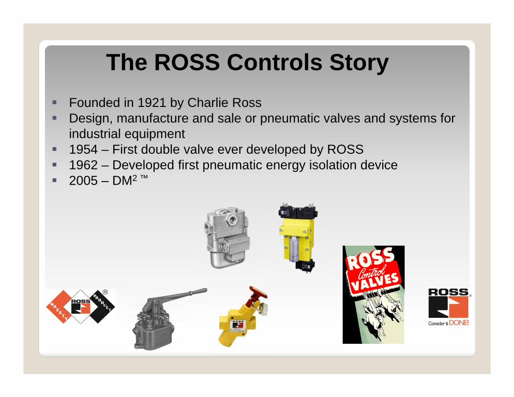
The ROSS Controls Story Founded in 1921 by Charlie Ross Design, manufacture and sale or pneumatic valves and systems for
industrial equipment 1954 – First double valve ever developed by ROSS 1962 – Developed first pneumatic energy isolation device 2005 – DM2 ™

Global Facilities
ROSS Controls - Madison Heights
ROSS Controls - Troy, MI ROSS UK Ltd.
ROSS Asia - Japan
ROSS Europa GmbH - Germany
ROSS Controls - Lavonia, GA
ROSS South America ROSS IndiaROSS China
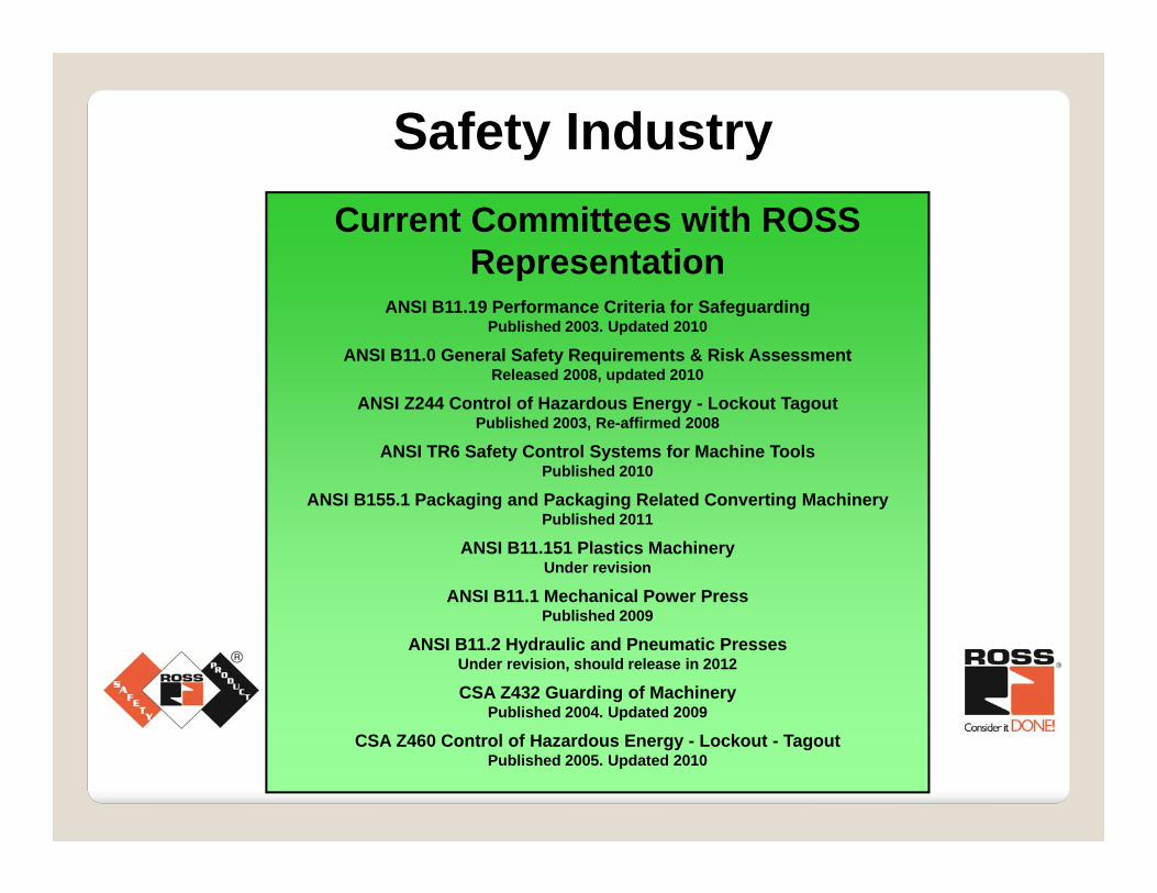
Safety IndustryCurrent Committees with ROSS
RepresentationANSI B11.19 Performance Criteria for Safeguarding
Published 2003. Updated 2010
ANSI B11.0 General Safety Requirements & Risk AssessmentReleased 2008, updated 2010
ANSI Z244 Control of Hazardous Energy - Lockout TagoutPublished 2003, Re-affirmed 2008
ANSI TR6 Safety Control Systems for Machine ToolsPublished 2010
ANSI B155.1 Packaging and Packaging Related Converting MachineryPublished 2011
ANSI B11.151 Plastics MachineryUnder revision
ANSI B11.1 Mechanical Power PressPublished 2009
ANSI B11.2 Hydraulic and Pneumatic PressesUnder revision, should release in 2012
CSA Z432 Guarding of MachineryPublished 2004. Updated 2009
CSA Z460 Control of Hazardous Energy - Lockout - TagoutPublished 2005. Updated 2010
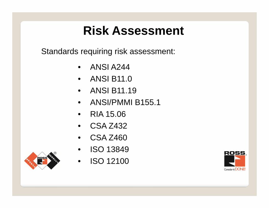
Risk AssessmentStandards requiring risk assessment:
• ANSI A244• ANSI B11.0• ANSI B11.19• ANSI/PMMI B155.1• RIA 15.06• CSA Z432• CSA Z460• ISO 13849• ISO 12100
• Risk Assessment
• Task based process
• Consider severity, frequency, & probability
• Consider foreseeable misuse & failure modes
Risk Assessment
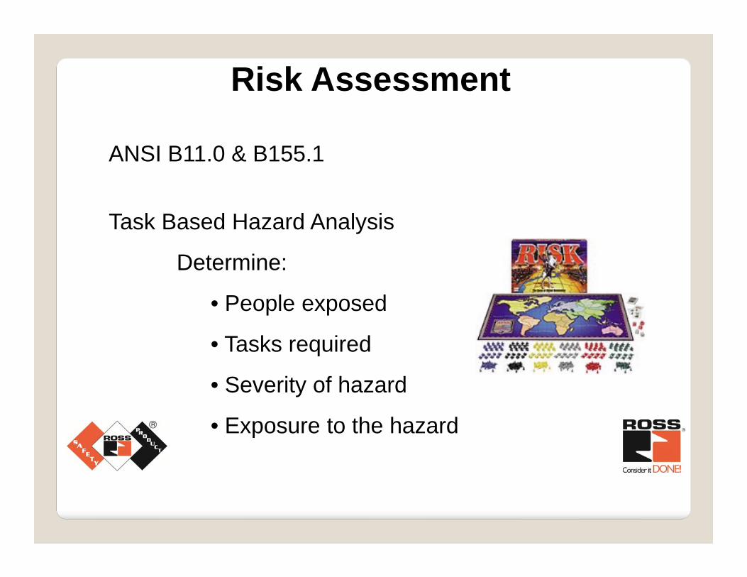
ANSI B11.0 & B155.1
Task Based Hazard Analysis
Determine:
• People exposed
• Tasks required
• Severity of hazard
• Exposure to the hazard
Risk Assessment
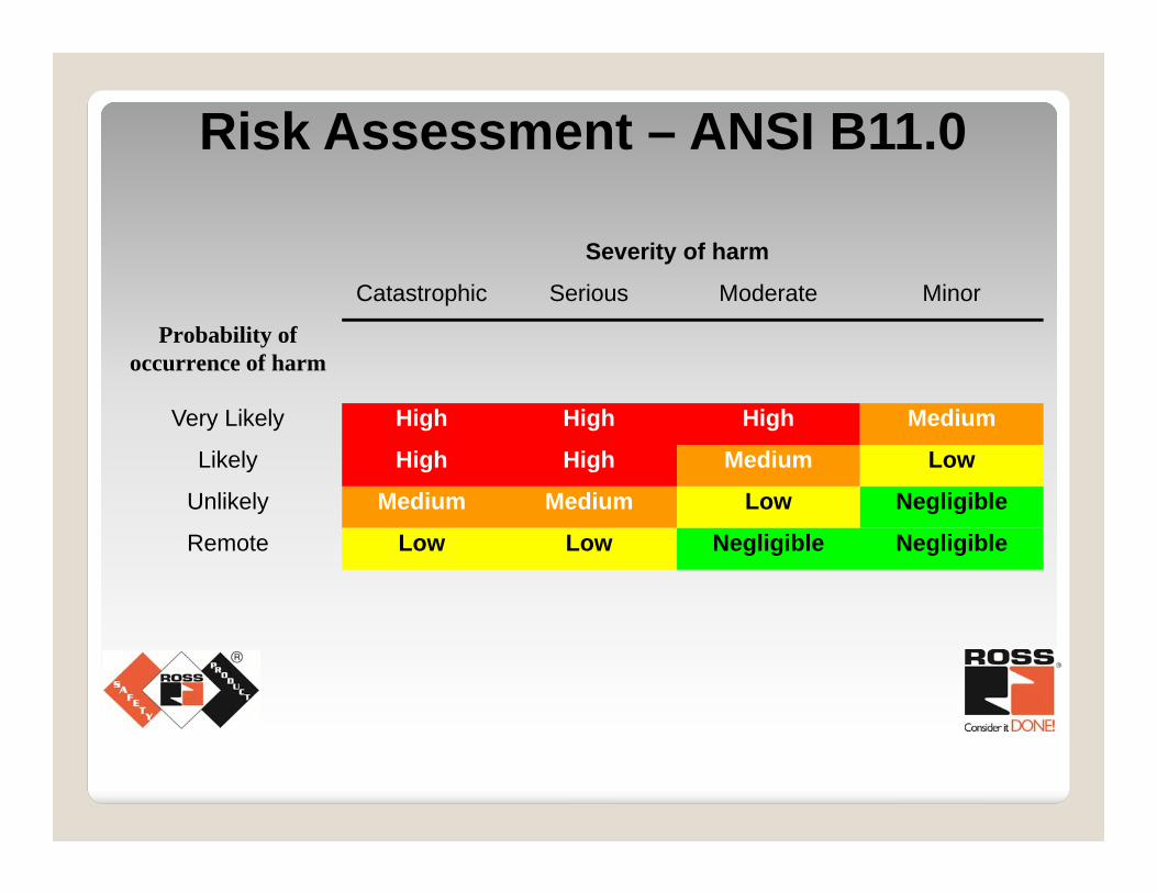
Severity of harm
Catastrophic Serious Moderate Minor
Probability of occurrence of harm
Very Likely High High High Medium
Likely High High Medium Low
Unlikely Medium Medium Low Negligible
Remote Low Low Negligible Negligible
Risk Assessment – ANSI B11.0
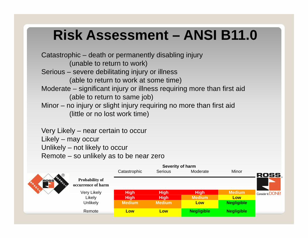
Risk Assessment – ANSI B11.0Catastrophic – death or permanently disabling injury
(unable to return to work)Serious – severe debilitating injury or illness
(able to return to work at some time)Moderate – significant injury or illness requiring more than first aid
(able to return to same job)Minor – no injury or slight injury requiring no more than first aid
(little or no lost work time)
Very Likely – near certain to occurLikely – may occurUnlikely – not likely to occurRemote – so unlikely as to be near zero
Severity of harmCatastrophic Serious Moderate Minor
Probability of occurrence of harm
Very Likely High High High MediumLikely High High Medium Low
Unlikely Medium Medium Low Negligible
Remote Low Low Negligible Negligible
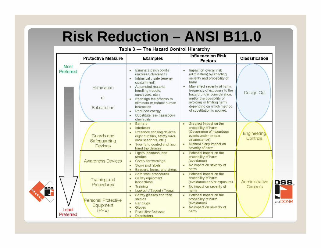
Risk Reduction – ANSI B11.0
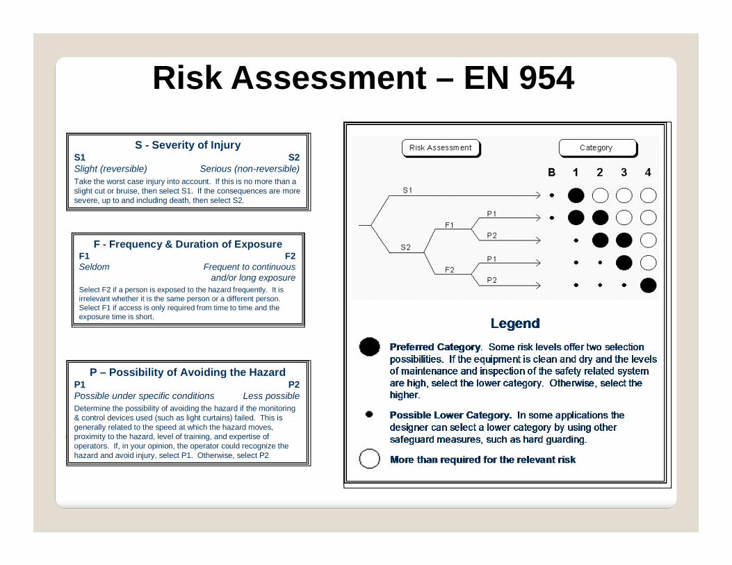
Risk Assessment – EN 954
P – Possibility of Avoiding the HazardP1 P2Possible under specific conditions Less possibleDetermine the possibility of avoiding the hazard if the monitoring & control devices used (such as light curtains) failed. This isgenerally related to the speed at which the hazard moves, proximity to the hazard, level of training, and expertise of operators. If, in your opinion, the operator could recognize the hazard and avoid injury, select P1. Otherwise, select P2
S - Severity of InjuryS1 S2Slight (reversible) Serious (non-reversible)Take the worst case injury into account. If this is no more than a slight cut or bruise, then select S1. If the consequences are more severe, up to and including death, then select S2.
F - Frequency & Duration of ExposureF1 F2Seldom Frequent to continuous
and/or long exposureSelect F2 if a person is exposed to the hazard frequently. It is irrelevant whether it is the same person or a different person. Select F1 if access is only required from time to time and the exposure time is short.
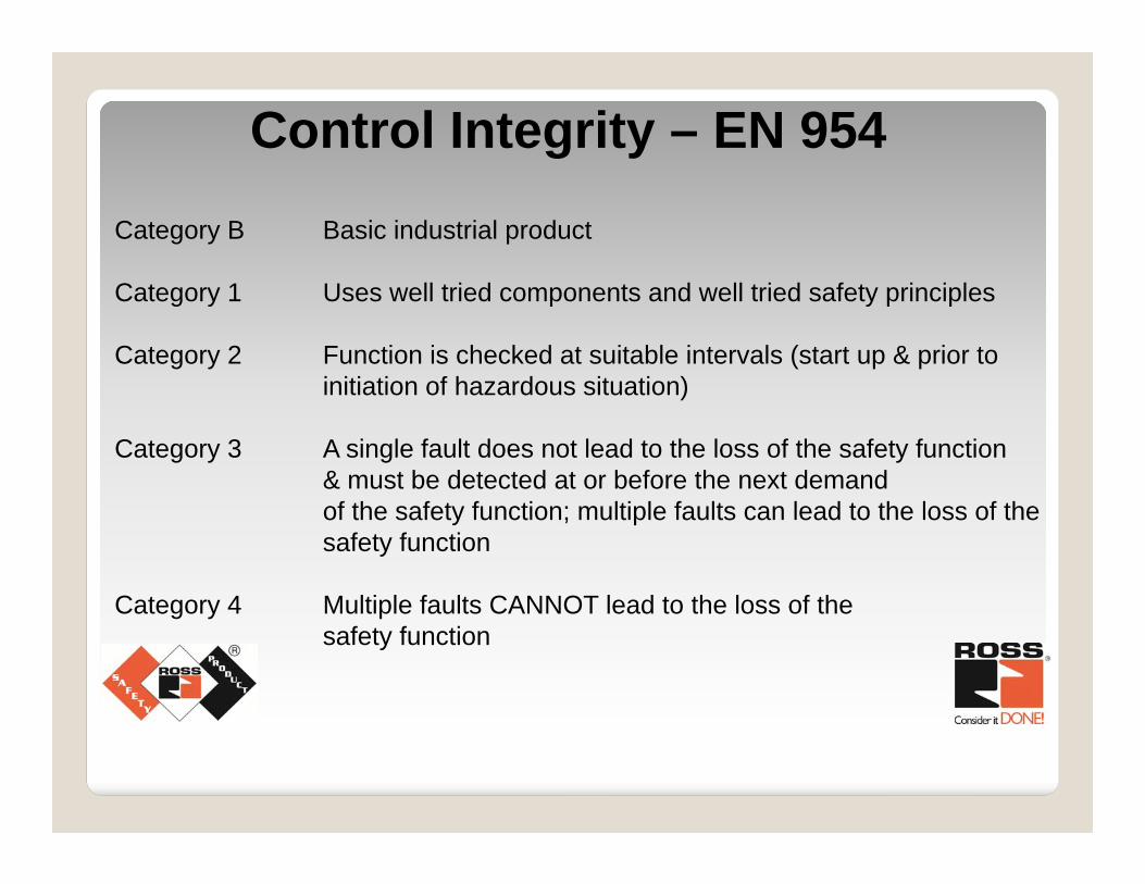
Category B Basic industrial product
Category 1 Uses well tried components and well tried safety principles
Category 2 Function is checked at suitable intervals (start up & prior to initiation of hazardous situation)
Category 3 A single fault does not lead to the loss of the safety function& must be detected at or before the next demandof the safety function; multiple faults can lead to the loss of thesafety function
Category 4 Multiple faults CANNOT lead to the loss of thesafety function
Control Integrity – EN 954
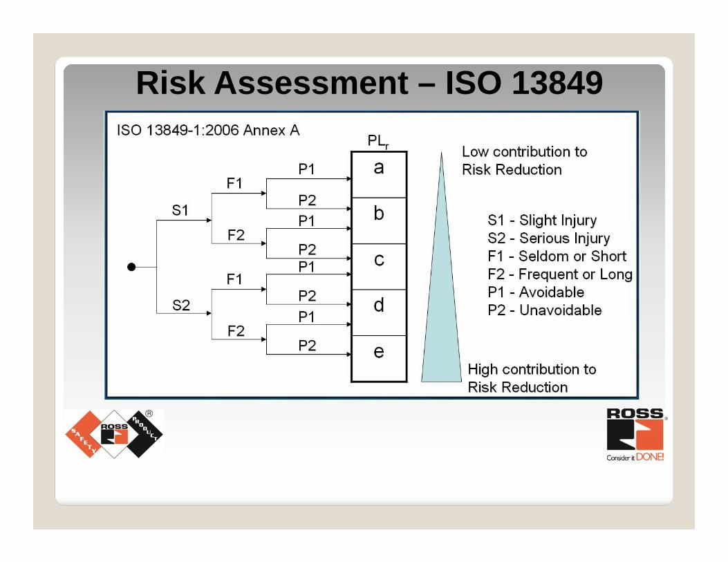
Risk Assessment – ISO 13849
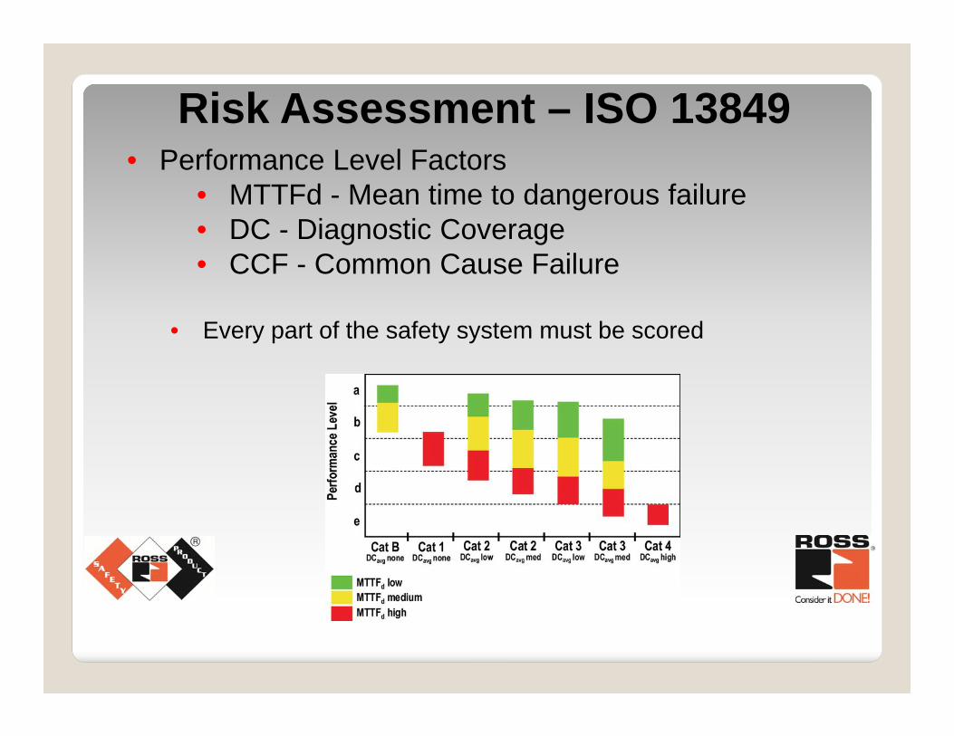
Risk Assessment – ISO 13849• Performance Level Factors
• MTTFd - Mean time to dangerous failure• DC - Diagnostic Coverage• CCF - Common Cause Failure
• Every part of the safety system must be scored
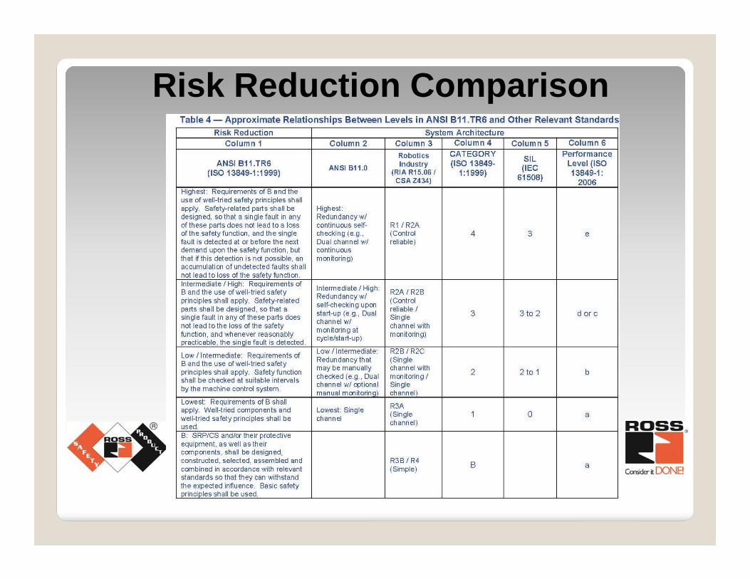
Risk Reduction Comparison
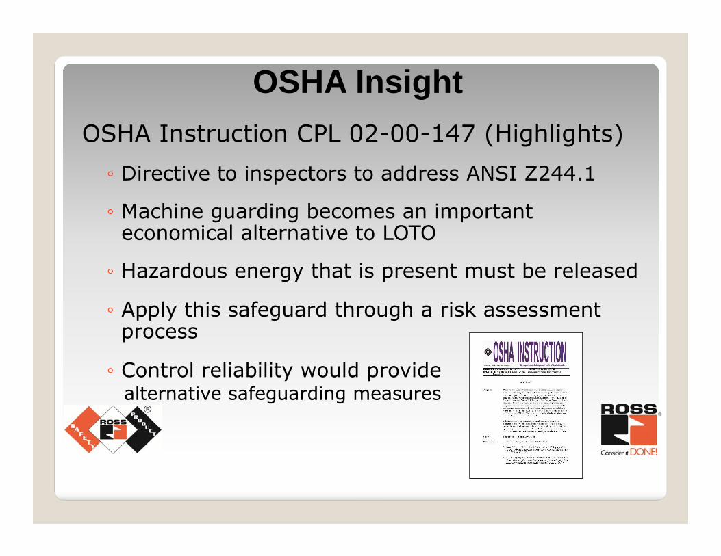
OSHA Instruction CPL 02-00-147 (Highlights)◦ Directive to inspectors to address ANSI Z244.1
◦ Machine guarding becomes an important economical alternative to LOTO
◦ Hazardous energy that is present must be released
◦ Apply this safeguard through a risk assessment process
◦ Control reliability would provide alternative safeguarding measures
OSHA Insight
Risk Assessment
Function of:
◦ Severity
◦ Frequency
◦ Avoidability
Fluid Power
Severity (Assume no guarding)
Function of:◦ Pressure & force◦ Tooling interface◦ Speed◦ Mass
Fluid Power Risk Assessment
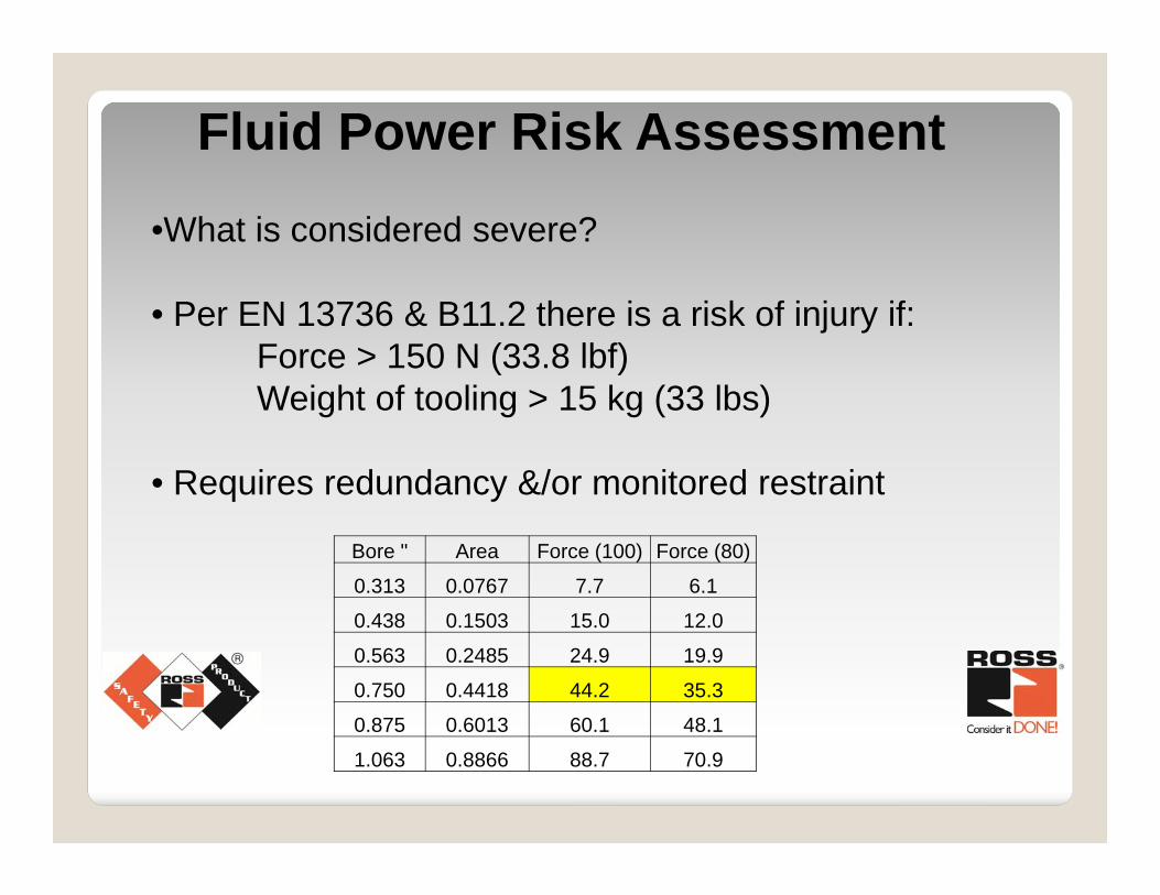
•What is considered severe?
• Per EN 13736 & B11.2 there is a risk of injury if:Force > 150 N (33.8 lbf)Weight of tooling > 15 kg (33 lbs)
• Requires redundancy &/or monitored restraint
Fluid Power Risk Assessment
Bore " Area Force (100) Force (80)
0.313 0.0767 7.7 6.1
0.438 0.1503 15.0 12.0
0.563 0.2485 24.9 19.9
0.750 0.4418 44.2 35.3
0.875 0.6013 60.1 48.1
1.063 0.8866 88.7 70.9
Frequency
◦ Manual operation (Loading or unloading)
◦ Jam clearing – How often?
◦ Maintenance
Fluid Power Risk Assessment
Avoidability
◦ What is the operational speed?
◦ Will there be awareness?
◦ With safeguarding: What is the stopping time? Has the safe distance calculation been completed Has depth of penetration been considered?
Fluid Power Risk Assessment
Must consider valve failure modes◦ Failure to shift◦ Failure to return◦ Seal leakage◦ Sudden pressure loss◦ Sudden pressurization◦ Slow shifting
Fluid Power Risk Assessment
Fluid Power Risk Assessment
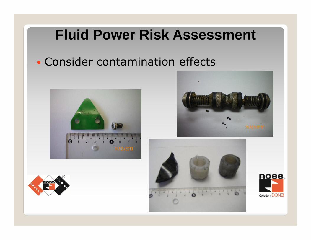
Consider contamination effects
Fluid Power Risk Assessment
• Design with desired outcome in mind• What happens when solenoid power is
removed?
• Consider valve faults and failures• Does the cylinder continue moving?• Does it not return?• Does a load fall?
Two primary desired results:
1. Remove fluid power pressure to prevent movement and a hazard (remove motive force)
2. Trap fluid power to prevent movement and a hazard or use mechanical means
Fluid Power Risk Assessment
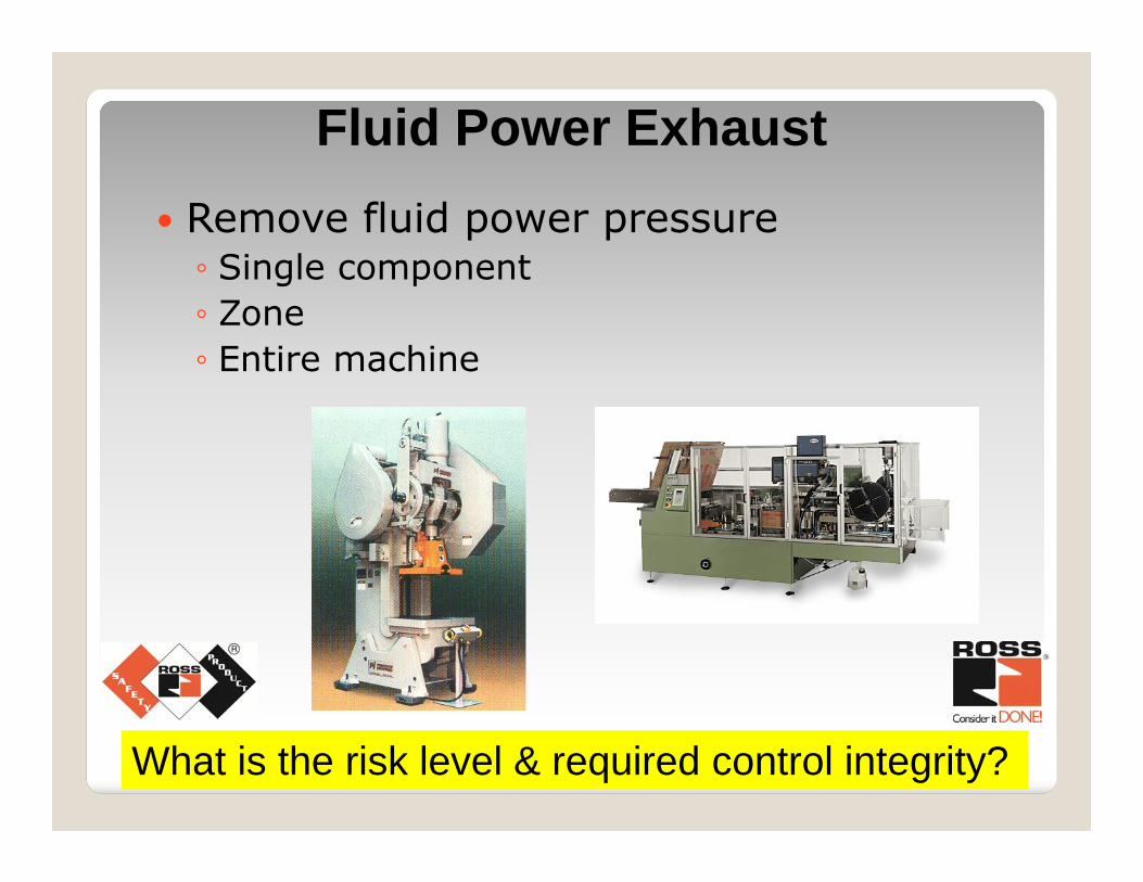
Fluid Power Exhaust Remove fluid power pressure◦ Single component◦ Zone◦ Entire machine
What is the risk level & required control integrity?
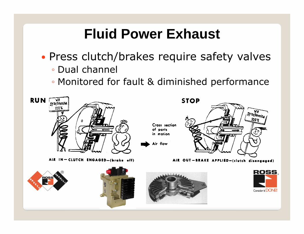
Fluid Power Exhaust Press clutch/brakes require safety valves ◦ Dual channel◦ Monitored for fault & diminished performance
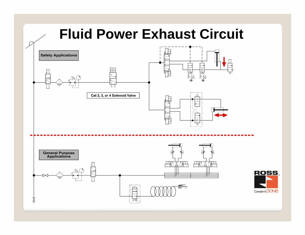
Fluid Power Exhaust Circuit
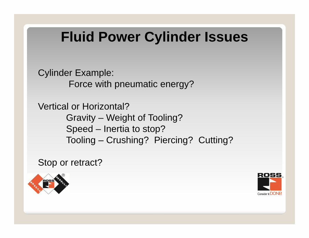
Cylinder Example:Force with pneumatic energy?
Vertical or Horizontal?Gravity – Weight of Tooling?Speed – Inertia to stop?Tooling – Crushing? Piercing? Cutting?
Stop or retract?
Fluid Power Cylinder Issues
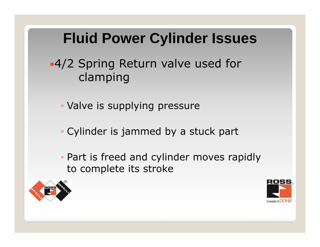
4/2 Spring Return valve used for clamping
◦ Valve is supplying pressure
◦ Cylinder is jammed by a stuck part
◦ Part is freed and cylinder moves rapidly to complete its stroke
Fluid Power Cylinder Issues
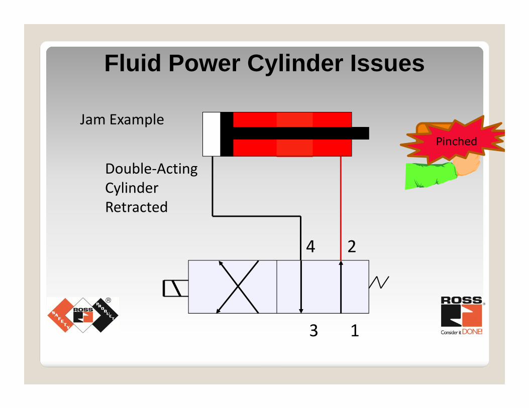
Double‐Acting Cylinder Retracted
1
2
3
4
Jam ExampleJamPinched
Fluid Power Cylinder Issues
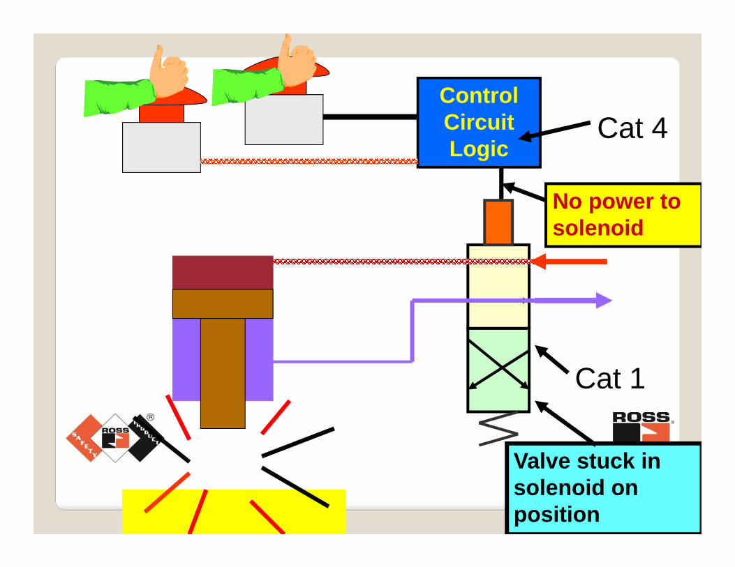
Control Circuit Logic
Valve stuck in solenoid on position
No power to solenoid
Cat 4
Cat 1
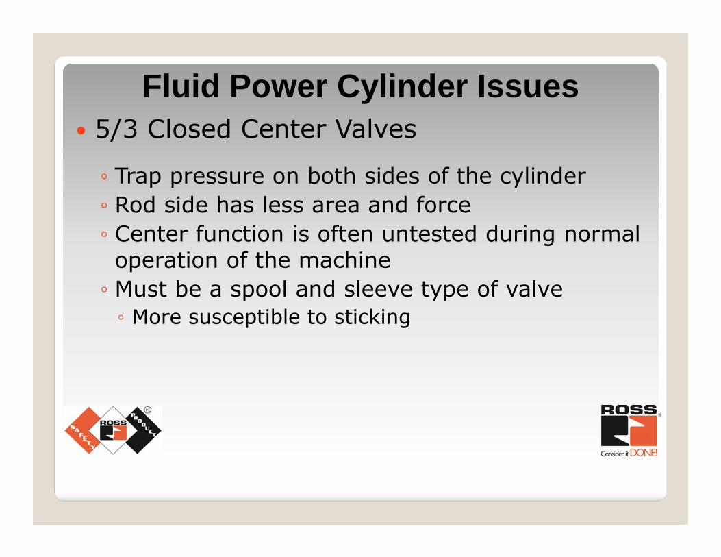
Fluid Power Cylinder Issues 5/3 Closed Center Valves
◦ Trap pressure on both sides of the cylinder◦ Rod side has less area and force◦ Center function is often untested during normal operation of the machine◦ Must be a spool and sleeve type of valve◦ More susceptible to sticking
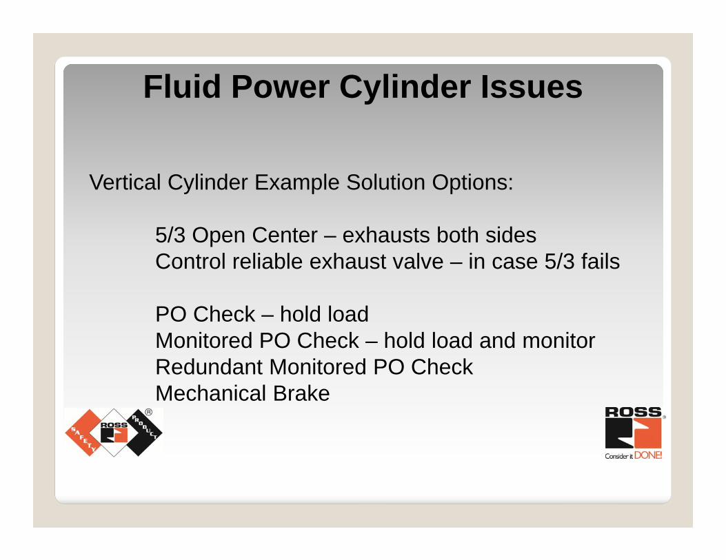
Vertical Cylinder Example Solution Options:
5/3 Open Center – exhausts both sidesControl reliable exhaust valve – in case 5/3 fails
PO Check – hold loadMonitored PO Check – hold load and monitorRedundant Monitored PO CheckMechanical Brake
Fluid Power Cylinder Issues
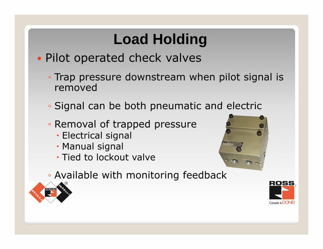
Pilot operated check valves◦ Trap pressure downstream when pilot signal is removed
◦ Signal can be both pneumatic and electric
◦ Removal of trapped pressure Electrical signal Manual signal Tied to lockout valve
◦ Available with monitoring feedback
Load Holding
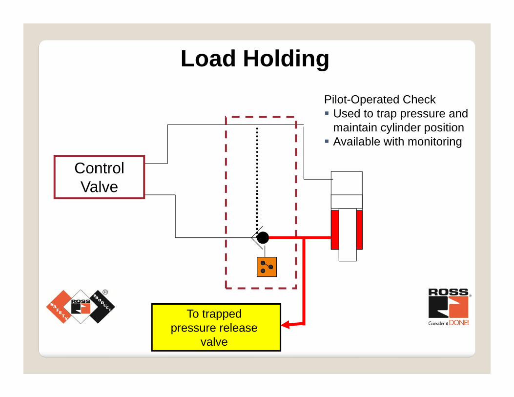
To trapped pressure release
valve
Control Valve
Pilot-Operated Check Used to trap pressure and
maintain cylinder position Available with monitoring
Load Holding
Mechanical Methods
◦ Hold platen or tooling
◦ Use spring loaded pins or cylinders
◦ Typically pneumatically actuated
Load Holding
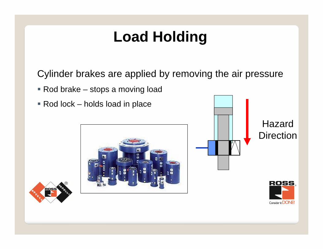
Cylinder brakes are applied by removing the air pressure Rod brake – stops a moving load
Rod lock – holds load in place
Hazard Direction
Load Holding
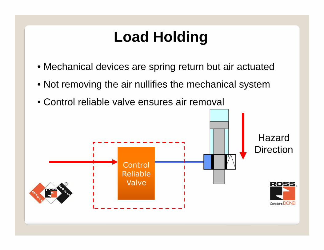
• Mechanical devices are spring return but air actuated
• Not removing the air nullifies the mechanical system
• Control reliable valve ensures air removal
Hazard Direction
Control Reliable Valve
Load Holding
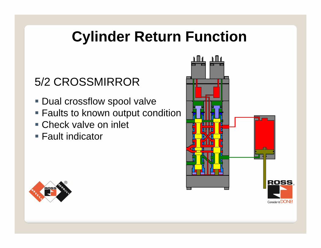
5/2 CROSSMIRROR Dual crossflow spool valve Faults to known output condition Check valve on inlet Fault indicator
Cylinder Return Function
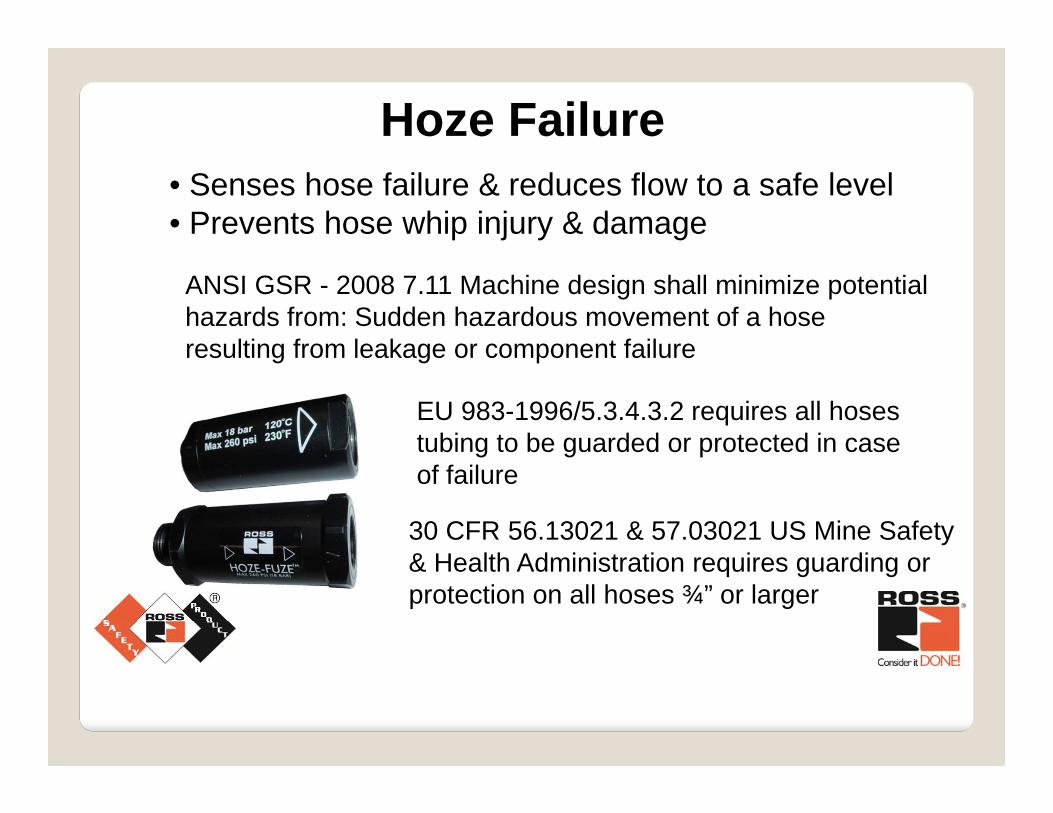
Hoze Failure• Senses hose failure & reduces flow to a safe level• Prevents hose whip injury & damage
EU 983-1996/5.3.4.3.2 requires all hoses tubing to be guarded or protected in case of failure
30 CFR 56.13021 & 57.03021 US Mine Safety & Health Administration requires guarding or protection on all hoses ¾” or larger
ANSI GSR - 2008 7.11 Machine design shall minimize potential hazards from: Sudden hazardous movement of a hose resulting from leakage or component failure
What can be done to address pneumatic hazards?
Remove the motive force – exhaust down stream air
Selectively trap pressure if needed Provide way to remove pressure
Use mechanical devices when required
Maintain the Control Integrity of the safety system
Safety Valves

Fluid Power Risk Assessment
Eric Cummings – ROSS CONTROLSGlobal Industry Manager - [email protected]
803-622-1161