Embed Size (px)
Citation preview

Proceedings of the 5th International Conference on Integrity-Reliability-Failure, Porto/Portugal 24-28 July 2016
Editors J.F. Silva Gomes and S.A. Meguid
Publ. INEGI/FEUP (2016)
-635-
PAPER REF: 6258
FLUID STRUCTURE INTERACTION IN OFFSHORE ENVIRONMENT
Daniel Oliveira1(*)
, Aldina Santiago2, Constança Rigueiro
3
1,2ISISE -
Department of Civil Engineering, University of Coimbra, Coimbra, Portugal
3ISISE -
School of Engineering, Polytechnic Institute of Castelo Branco (IPCB), Castelo Branco, Portugal
(*)Email: [email protected]
ABSTRACT
The increasing use of oil enlarged its exploration to offshore environmental. The deposits
found appeared very deeply, leading to the need to build stable structures that support its
extraction. Therefore, environmental conditions on offshore structures exhibit dynamic, non-
linear and unpredictable behavior, which makes the analysis of these structures one of the
most demanding tasks of structural engineering. A recent and powerful method to analyze a
fluid-structure interaction is using numerical software with the capability of Computational
Fluid Dynamics (CFD) modelling.
In this study, a one-way coupled Fluid-Structure Interaction (FSI) between hydrodynamic
loads and a jacket offshore platform structure was modelled. This problem was divided in two
parts: a structural model (jacket) and a Volume Of Fluid (VOF) based on hydrodynamics
models. To synchronize data between these two models, an interface was defined. The
structure was modelled in ABAQUS with a 3D Finite Element (FE) model with the aim to
determine the deformation caused by environmental actions, namely hydrodynamic loads
induced by waves and current. The environmental conditions were modelled in STAR-
CCM+, using a Computational Fluid Dynamics (CFD). It was used an implicit time
integration in both models and the data was synchronized explicitly, one iteration per time
step. The main objectives of this study were: i) investigate the recent capabilities of STAR-
CCM+ to model linear and non-linear waves; ii) to understand how to carry out a co-
simulation with ABAQUS, and iii) to demonstrate how it can be used in the structural design
and optimization stages.
Keywords: Fluid structure interaction, offshore platforms, hydrodynamic loads,
computational fluid dynamics, STAR-CCM+, finite elements; ABAQUS.
INTRODUCTION
The increasing use of oil, enlarged its exploration to offshore environmental. The deposits
found appeared very deep, leading to the need to build stable structures that support its
extraction. Therefore, environmental conditions on offshore structures exhibit extremely
dynamic, non-linear and unpredictable behavior. It makes the analysis of these structures one
of the most demanding tasks of structural engineering.
The Fluid-Structure Interaction (FSI) is a field of studies which has as principal objective
analyse the influence of an internal or surrounding fluid flow on one or more solid structures.
The FSI analysis are very complex due to the multidisciplinary nature and strong non-
linearity of both (fluid and structure). This type of interaction can be observed in a wide range

Topic_L: Energy and Thermo-Fluid Systems
-636-
of engineering and scientific fields, such as wind action on buildings (structural engineering)
and the interaction between the blood flow and an artificial heart valve (medicine).
In offshore environment, the interaction between the dynamic loads (waves, current and wind)
and the platforms has been studied with the main objective to help the engineer in the design
and optimization stages. These studies have been done using experimental tests, which
demonstrate to be a good method to predict the structural response of the platforms under
environmental conditions. However, it requires a huge space for the wave tank. So, for
practical reasons it is necessary to use scale models which induce scale effects on the results;
additionally, it is necessary to simplify the proprieties of the structural material which affect
the structural response, and a limited number of measurements is possible, making the
quantification of the fluid behavior in detail very difficult.
Nowadays, these complex analysis can be also studied using numerical methods. It allows: i)
to study the system in real scale, ii) the modelling of the detailed structural response of the
structure, iii) to quantify in detail the fluid and the structural behavior at any point of the
model and iv) to reduce the cost (time and money) at the stage of the construction of the
models but also during the analyses of the results. However, this method cannot predict
unexpected physical phenomes once there are applied only the physics already known. On the
other hand this limitation can be overcome by comparing the numerical results with the
experimental ones.
The current study case corresponds to a real scale-model of a tubular steel jacket offshore
structure located at Western Gulf of Mexico (95º W) under hydrodynamic actions (waves and
current). This interaction was analyzed by the numerical method using a one-way FSI
coupling method with a Computational Fluid Dynamics (CFD) solver (STAR-CCM+) and a
Computational Solid Mechanics (CSM) solver (ABAQUS). The main objective is to
demonstrate that this coupling method is a powerful tool to predict the system (fluid-
structure) response under these conditions [1].
2. FLUID-STRUCTURE INTERACTION MODEL
Since the collapse of the Tacoma Narrows Bridge (1940) caused by the wind action, the
structural engineers start to pay more attention to the fluid-structure interaction at the design
stage. The powerful numerical solvers have been recently used to study a wide variety of FSI
problems of offshore platforms [2 - 7].
With numerical analyzes, the systems can be modelled by two different approaches:
monolithic approach and partitioned approach. The monolithic approach use a unified
algorithm (a single system equation) for the entire problem. It means that it is an accurate
method but at the same time it is required to develop a specific algorithm for each case [8, 9].
In contrast, with the partitioned approach the fluid and the structure are treated separately in
two different algorithms (CFD and CSM) where the results are shared by an interface.
Using this coupling method, the results of each solver can be shared using two different
schemes: one-way and two-way coupling (Fig. 1). The one-way coupling is used in FSI
problems where the fluid motion is slight affected by the structural response; in these cases
only the pressures calculated by CFD model are transferred to the structural model (structure
is rigid in the CFD model). Both solvers run separately and the data is transferred explicitly
(in 1 iteration at the end of the time-step). In the other hand, the two-way coupling is used
when the fluid flow is significantly affected by the structural response, introducing changes in
the pressure field in the interface. This process can be explicit or implicit (iterative process,

Proceedings of the 5th International Conference on Integrity-Reliability-Failure
-637-
the data is shared during the time-step and a new one is only started after reach the
convergence level of the results required) [8, 9].
As the jacket platforms are design to show a rigid behavior which slight affect the fluid flow,
a one-way FSI coupling scheme was used in the current study.
Fig. 1- Solution algorithm for one-way and two-way coupling schemes
LOADS ON OFFSHORE ENVIRONMENTAL
Introduction
Due to the location and use of offshore platforms, it is extremely important to identify and
understand which type of actions should be considered on the structural analysis. There are
four different types of actions:
- permanent actions: they correspond to the ones which variations in magnitude with time
are negligible in relation to the mean value (self-weight of structures; self-weight of fixed
equipment, etc.);
- variable actions: they are generally caused by the use (ex: machine’s vibration) and
occupancy (self-weight of people and temporary equipment);
- environmental actions: they are distinct from the variable actions because they are
generated due to environmental phenomenon (such as wind, waves and current, marine
growth, ice, temperature, earthquakes, etc.);
- accidental actions: collisions, dropped objects, fires and explosions are the main
accidental actions that are required to consider in the design stage [10].
In this case only the hydrodynamics actions (waves and current) were considered on the
structural analysis of a jacket platform.
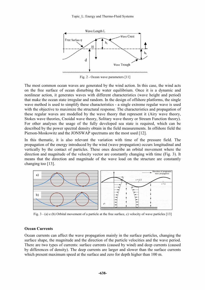
Ocean Waves
The waves are distinct in mechanical and electromagnetic waves. The ocean waves are
classified as mechanical waves once they are generated by physical disturb on the
environment. The characteristics of these waves are defined by the wave period (T), the crest
height (hc) and the trough height (ht). The wave height (H = hc + ht) and the water depth (d)
are represented in Fig. 2.
CSM Solver CSM Solver CSM Solver
1 1 (After convergence of steps
2 and 4)
Topic_L: Energy and Thermo-Fluid Systems
-638-
Fig. 2 - Ocean wave parameters [11]
The most common ocean waves are generated by the wind action. In this case, the wind acts
on the free surface of ocean disturbing the water equilibrium. Once it is a dynamic and
nonlinear action, it generates waves with different characteristics (wave height and period)
that make the ocean state irregular and random. In the design of offshore platforms, the single
wave method is used to simplify these characteristics - a single extreme regular wave is used
with the objective to maximize the structural response. The characteristics and propagation of
these regular waves are modelled by the wave theory that represent it (Airy wave theory,
Stokes wave theories, Cnoidal wave theory, Solitary wave theory or Stream Function theory).
For other analyses the usage of the fully developed sea state is required, which can be
described by the power spectral density obtain in the field measurements. In offshore field the
Pierson-Moskowitz and the JONSWAP spectrums are the most used [12].
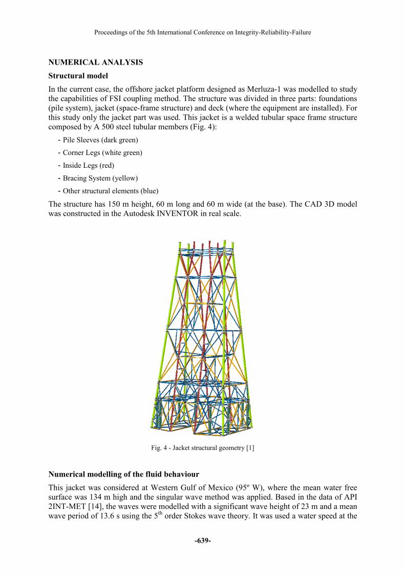
In this thematic, it is also relevant the variation with time of the pressure field. The
propagation of the energy introduced by the wind (wave propagation) occurs longitudinal and
vertically by the contact of particles. These ones describe an orbital movement where the
direction and magnitude of the velocity vector are constantly changing with time (Fig. 3). It
means that the direction and magnitude of the wave load on the structure are constantly
changing too [13].
Fig. 3 - (a) e (b) Orbital movement of a particle at the free surface, c) velocity of wave particles [13]
Ocean Currents
Ocean currents can affect the wave propagation mainly in the surface particles, changing the
surface shape, the magnitude and the direction of the particle velocities and the wave period.
There are two types of currents: surface currents (caused by wind) and deep currents (caused
by differences of density). The deep currents are larger and slower than the surface currents
which present maximum speed at the surface and zero for depth higher than 100 m.
d
c
Proceedings of the 5th International Conference on Integrity-Reliability-Failure
-639-
NUMERICAL ANALYSIS
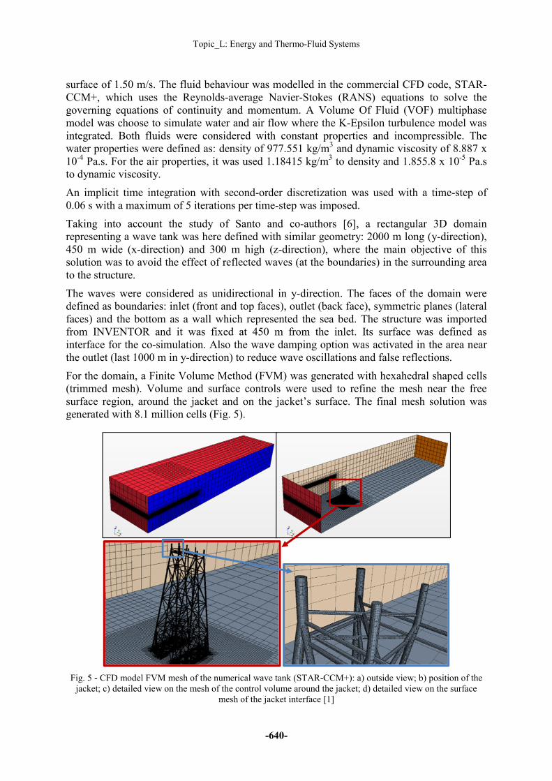
Structural model
In the current case, the offshore jacket platform designed as Merluza-1 was modelled to study
the capabilities of FSI coupling method. The structure was divided in three parts: foundations
(pile system), jacket (space-frame structure) and deck (where the equipment are installed). For
this study only the jacket part was used. This jacket is a welded tubular space frame structure
composed by A 500 steel tubular members (Fig. 4):
- Pile Sleeves (dark green)
- Corner Legs (white green)
- Inside Legs (red)
- Bracing System (yellow)
- Other structural elements (blue)
The structure has 150 m height, 60 m long and 60 m wide (at the base). The CAD 3D model
was constructed in the Autodesk INVENTOR in real scale.
Fig. 4 - Jacket structural geometry [1]
Numerical modelling of the fluid behaviour
This jacket was considered at Western Gulf of Mexico (95º W), where the mean water free
surface was 134 m high and the singular wave method was applied. Based in the data of API
2INT-MET [14], the waves were modelled with a significant wave height of 23 m and a mean
wave period of 13.6 s using the 5th
order Stokes wave theory. It was used a water speed at the
Topic_L: Energy and Thermo-Fluid Systems
-640-
surface of 1.50 m/s. The fluid behaviour was modelled in the commercial CFD code, STAR-
CCM+, which uses the Reynolds-average Navier-Stokes (RANS) equations to solve the
governing equations of continuity and momentum. A Volume Of Fluid (VOF) multiphase
model was choose to simulate water and air flow where the K-Epsilon turbulence model was
integrated. Both fluids were considered with constant properties and incompressible. The
water properties were defined as: density of 977.551 kg/m3 and dynamic viscosity of 8.887 x
10-4
Pa.s. For the air properties, it was used 1.18415 kg/m3 to density and 1.855.8 x 10
-5 Pa.s
to dynamic viscosity.
An implicit time integration with second-order discretization was used with a time-step of
0.06 s with a maximum of 5 iterations per time-step was imposed.
Taking into account the study of Santo and co-authors [6], a rectangular 3D domain
representing a wave tank was here defined with similar geometry: 2000 m long (y-direction),
450 m wide (x-direction) and 300 m high (z-direction), where the main objective of this
solution was to avoid the effect of reflected waves (at the boundaries) in the surrounding area
to the structure.
The waves were considered as unidirectional in y-direction. The faces of the domain were
defined as boundaries: inlet (front and top faces), outlet (back face), symmetric planes (lateral
faces) and the bottom as a wall which represented the sea bed. The structure was imported
from INVENTOR and it was fixed at 450 m from the inlet. Its surface was defined as
interface for the co-simulation. Also the wave damping option was activated in the area near
the outlet (last 1000 m in y-direction) to reduce wave oscillations and false reflections.
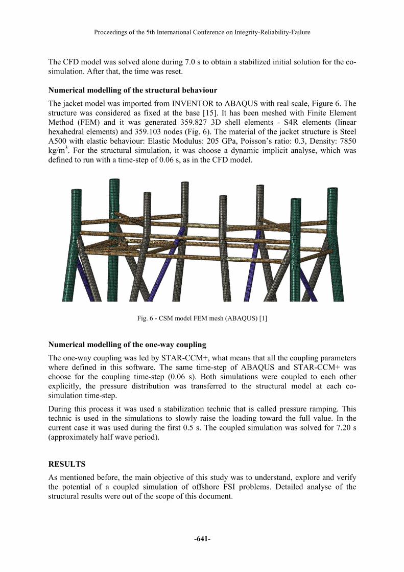
For the domain, a Finite Volume Method (FVM) was generated with hexahedral shaped cells
(trimmed mesh). Volume and surface controls were used to refine the mesh near the free
surface region, around the jacket and on the jacket’s surface. The final mesh solution was
generated with 8.1 million cells (Fig. 5).
Fig. 5 - CFD model FVM mesh of the numerical wave tank (STAR-CCM+): a) outside view; b) position of the
jacket; c) detailed view on the mesh of the control volume around the jacket; d) detailed view on the surface
mesh of the jacket interface [1]
Proceedings of the 5th International Conference on Integrity-Reliability-Failure
-641-
The CFD model was solved alone during 7.0 s to obtain a stabilized initial solution for the co-
simulation. After that, the time was reset.
Numerical modelling of the structural behaviour
The jacket model was imported from INVENTOR to ABAQUS with real scale, Figure 6. The
structure was considered as fixed at the base [15]. It has been meshed with Finite Element
Method (FEM) and it was generated 359.827 3D shell elements - S4R elements (linear
hexahedral elements) and 359.103 nodes (Fig. 6). The material of the jacket structure is Steel
A500 with elastic behaviour: Elastic Modulus: 205 GPa, Poisson’s ratio: 0.3, Density: 7850
kg/m3. For the structural simulation, it was choose a dynamic implicit analyse, which was
defined to run with a time-step of 0.06 s, as in the CFD model.
Fig. 6 - CSM model FEM mesh (ABAQUS) [1]
Numerical modelling of the one-way coupling
The one-way coupling was led by STAR-CCM+, what means that all the coupling parameters
where defined in this software. The same time-step of ABAQUS and STAR-CCM+ was
choose for the coupling time-step (0.06 s). Both simulations were coupled to each other
explicitly, the pressure distribution was transferred to the structural model at each co-
simulation time-step.
During this process it was used a stabilization technic that is called pressure ramping. This
technic is used in the simulations to slowly raise the loading toward the full value. In the
current case it was used during the first 0.5 s. The coupled simulation was solved for 7.20 s
(approximately half wave period).
RESULTS
As mentioned before, the main objective of this study was to understand, explore and verify
the potential of a coupled simulation of offshore FSI problems. Detailed analyse of the
structural results were out of the scope of this document.
Topic_L: Energy and Thermo-Fluid Systems
-642-
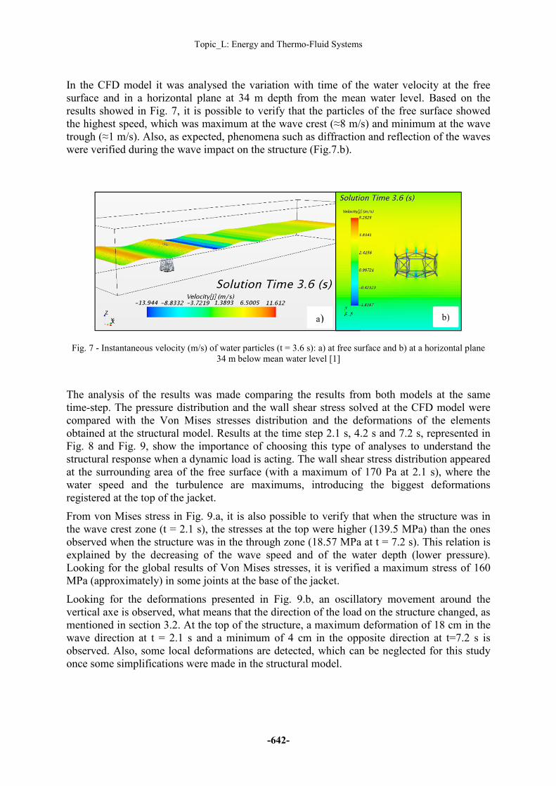
In the CFD model it was analysed the variation with time of the water velocity at the free
surface and in a horizontal plane at 34 m depth from the mean water level. Based on the
results showed in Fig. 7, it is possible to verify that the particles of the free surface showed
the highest speed, which was maximum at the wave crest (≈8 m/s) and minimum at the wave
trough (≈1 m/s). Also, as expected, phenomena such as diffraction and reflection of the waves
were verified during the wave impact on the structure (Fig.7.b).
Fig. 7 - Instantaneous velocity (m/s) of water particles (t = 3.6 s): a) at free surface and b) at a horizontal plane
34 m below mean water level [1]
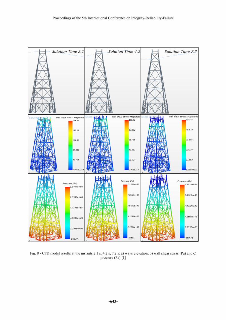
The analysis of the results was made comparing the results from both models at the same
time-step. The pressure distribution and the wall shear stress solved at the CFD model were
compared with the Von Mises stresses distribution and the deformations of the elements
obtained at the structural model. Results at the time step 2.1 s, 4.2 s and 7.2 s, represented in
Fig. 8 and Fig. 9, show the importance of choosing this type of analyses to understand the
structural response when a dynamic load is acting. The wall shear stress distribution appeared
at the surrounding area of the free surface (with a maximum of 170 Pa at 2.1 s), where the
water speed and the turbulence are maximums, introducing the biggest deformations
registered at the top of the jacket.
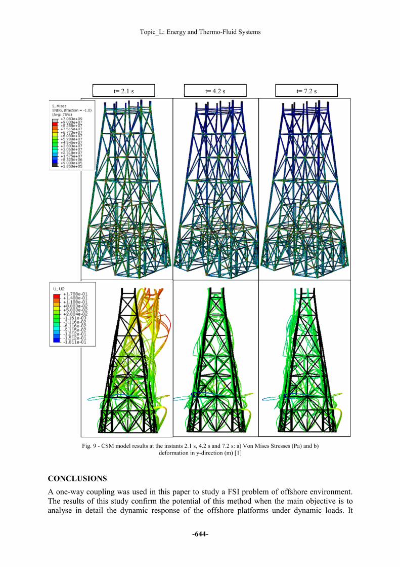
From von Mises stress in Fig. 9.a, it is also possible to verify that when the structure was in
the wave crest zone (t = 2.1 s), the stresses at the top were higher (139.5 MPa) than the ones
observed when the structure was in the through zone (18.57 MPa at t = 7.2 s). This relation is
explained by the decreasing of the wave speed and of the water depth (lower pressure).
Looking for the global results of Von Mises stresses, it is verified a maximum stress of 160
MPa (approximately) in some joints at the base of the jacket.
Looking for the deformations presented in Fig. 9.b, an oscillatory movement around the
vertical axe is observed, what means that the direction of the load on the structure changed, as
mentioned in section 3.2. At the top of the structure, a maximum deformation of 18 cm in the
wave direction at t = 2.1 s and a minimum of 4 cm in the opposite direction at t=7.2 s is
observed. Also, some local deformations are detected, which can be neglected for this study
once some simplifications were made in the structural model.
a) b)
Proceedings of the 5th International Conference on Integrity-Reliability-Failure
-643-
Fig. 8 - CFD model results at the instants 2.1 s, 4.2 s, 7.2 s: a) wave elevation, b) wall shear stress (Pa) and c)
pressure (Pa) [1]
Topic_L: Energy and Thermo-Fluid Systems
-644-
Fig. 9 - CSM model results at the instants 2.1 s, 4.2 s and 7.2 s: a) Von Mises Stresses (Pa) and b)
deformation in y-direction (m) [1]
CONCLUSIONS
A one-way coupling was used in this paper to study a FSI problem of offshore environment.
The results of this study confirm the potential of this method when the main objective is to
analyse in detail the dynamic response of the offshore platforms under dynamic loads. It
t= 2.1 s t= 4.2 s t= 7.2 s
Proceedings of the 5th International Conference on Integrity-Reliability-Failure
-645-
shows that it can be useful to help the engineers not only at the design and optimization stages
but also to understand events recorded in already installed structures.
Analysing the global response of the structure (Von Mises stresses and deformations), it is
possible to verify that the jacket is able to withstand the hydrodynamic loads induced by
waves and current.
ACKNOWLEDGMENTS
This work is financed by FEDER funds through the Competitivity Factors Operational
Programme - COMPETE and by national funds through FCT – Foundation for Science and
Technology within the scope of the project POCI-01-0145-FEDER-007633
REFERENCES
[1]-Oliveira, D. (2016). “Fluid Structure Interaction in Offshore Environment”. Master
Thesis, Department of Civil Engineering of University of Coimbra, Coimbra, Portugal.
[2]-Kim, J., Magee, A., Guan, K. (2011). “CFD Simulation of Flow-Inuced Motions of a
Multi-Column Floating Platform”. ASME 2011 30th International Conference on Ocean,
Offshore and Artic Engineering (OMAE), Vol. 7: CFD and VIV; Offshore Geotecnhics, pp.
319-326, Rotterdam, The Netherlands.
[3]-Lefevre, C., Constantinides, Y., Kim, J., Henneke, M., Jang, H., Gordon, R., Wu, G.
(2013). “Guidelines for CFD Simulations of SPAR VIM”. Proceedings of the ASME 32nd
International Conference on Ocean, Offshore and Artic Engineering, Nantes, France.
[4]-Kim, J., Jang, H., O’Sullivan, J. (n.d.). “A Cost-Effective Computational Tool For
Offshore Floater Design”.
[5]-Marzban, A., Lakshmiraju, M., Richardson, N., Henneke, M., Wu, G., Vargas, P., Oakley,
O. (2012). “Offshore Platform Fluid Structure Interaction Simulation”. Proceedings of the
ASME 31nd International Conference on Ocean, Offshore and Artic Engineering, Rio de
Janeiro, Brazil.
[6]-Santo, H., Taylor, P., Bai, W., Choo, Y. (2015). “Current blockage in a numerical wave
tank: 3D simulations of regular waves and currents through a porous tower”. Computers &
Fluids 115, pp. 256-269.
[7]-Peric, M. (2008). “Marine Issues”. Marine Special Report - Revista Dynamics, 39th
Edition, pág. 3. CD-Adapco.
[8]-STAR-CCM+ User’s manual - Version 10.06.010 (2015). CD-Adapco, USA.
[9]-Benra, F., Dohmen, H., Pei, J., Schuster, S., Wan, B. (2011). “A Comparison of One-Way
and Two.Way Coupling Methods for Numerical Analysis of Fluid-Structure Interactions”.
Journal of Applied Mathematics, Vol. 2011, 16 pages.
[10]-International Organization for Standardization (2002). “ISO 19900 – Petroleum and
natural gas industries - General Requirements for Offshore Structures”. Ed. 1, ISO, Geneva.
[11]-Pipeline Encyclopedia@ (n.d.). “Wave”. http://4.bp.blogspot.com/-VwPH6Lk66E0/Uz
Topic_L: Energy and Thermo-Fluid Systems
-646-
O3SlO9NQI/AAAAAAAAAJo/09I-kxRktVU/s1600/wave+length.png
[12]-Chakrabarti, S. (2005). “Handbook of Offshore Engineering”. Offshore Structures
Analysis, Inc., Plainfield, Illinois, USA.
[13]-Supporting Documents of the Training Course on Design of Offshore Structures - 2nd
Edition (2015), Coimbra, Portugal.
[14]-American Petroleum Institute (1993). “API RP 2A (LRFD) - Recommended Practice for
Planning, Designing and Constructing Fixed Offshore Platforms - Load and Resistance Factor
Design”. Ed.1, API, Washington.
[15]-Rimola, B. (2010). “Análise dinâmica de plataformas de aço para produção de petróleo
com base na consideração do efeito da interação solo-estrutura”. Master Thesis, Faculty of
Engineering of University of Estado do Rio de Janeiro, Brazil.