Embed Size (px)
Citation preview
SECED 2015 Conference: Earthquake Risk and Engineering towards a Resilient World 9-10 July 2015, Cambridge UK
FLUID STRUCTURE INTERACTION VS. LUMPED MASS ANALOGUE FOR STORAGE TANK SEISMIC ASSESSMENT
Rupert GIBSON1, Amar MISTRY2, James GO3 and Ziggy LUBKOWSKI4
Abstract: In order to effectively assess large fluid storage tank foundations under seismic loading, it is necessary to run a series of Dynamic Soil Structure Interaction (DSSI) analyses. Traditionally, the behaviour of the enclosed liquid is simulated using a lumped mass analogue representing the impulsive and convective masses. Although this method captures the overall response of the structure, the structural demand in the tank shell cannot be assessed as the analogue is dependent on the tank shell being considered as rigid. An alternative method has been developed that considers Fluid Structure Interaction (FSI) with the fluid explicitly simulated and in contact with the steel shell of the tank. A comparison between the two analysis methods has been completed and the distribution of pile forces was found to be particularly sensitive to the approach used. The lumped mass model with a rigid base plate predicted significantly higher axial forces in the outer ring of piles. With the more representative stiffness in the FSI model, the tank base plate and concrete raft were allowed to dish. This mobilised the central piles to generate a more even distribution of forces, allowing the foundation to be optimised with potential for reducing material quantities whilst still achieving adequate behaviour. Introduction The dynamic behaviour of the enclosed liquid in a large fluid storage tank can be represented by a combination of two types of behaviour modes; the impulsive (rigid body) and the convective (sloshing). The conventional method for simulating these behaviours is by using a lumped mass analogue for the impulsive and convective masses (Malhotra 2000). This method captures the overall response of the structure, however, the structural demand in the tank shell cannot be assessed as the analogue is dependent on the tank shell being considered as rigid. An alternative method has been developed as part of the design/assessment of a diesel storage tank that considers FSI with the fluid explicitly simulated and in contact with the steel shell of the tank (see Figure 1). Using the FSI modelling method enabled demands on the tank shell and anchor bolts; base plate to concrete raft sliding; expected slosh heights; foundation dishing; stresses in the concrete raft; and a more representative pile force distribution to be assessed. A lumped mass version of the DSSI model was also generated in order to verify the global behaviour of the FSI model. LS-DYNA (2012), a general purpose 3D nonlinear finite element program, was used to perform the 3D DSSI analyses. Due to its explicit time-integration and highly efficient algorithms it is particularly suited to FE models involving high degrees of nonlinearity. LS-DYNA has been verified and used successfully for DSSI analyses of tanks and other structures (e.g. Lubkowski et al 2004 and Chang et al 2012).
1 Senior Engineer, Arup, London, [email protected] 2 Engineer, Arup, London, [email protected] 3 Senior Engineer, Arup, London, [email protected] 4 Associate Director, Arup, London, [email protected]
Rupert GIBSON1, Amar MISTRY2, James GO3 and Ziggy LUBKOWSKI4
2
The FSI DSSI Model The DSSI model consists of the above-ground structural model or superstructure, the below-ground foundation or substructure, and the soil model (see Figure 1). The model also includes FSI with the diesel fluid explicitly simulated and in contact with the steel shell of the tank.
Figure 1. The DSSI & FSI model of diesel storage tank
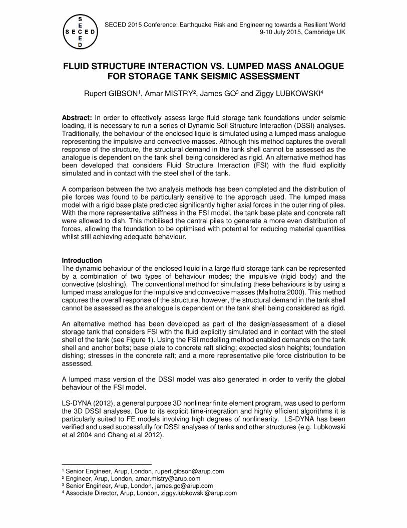
Superstructure The above-ground structure consists of a Ø23m diesel storage tank mounted on a reinforced concrete raft. The tank was modelled explicitly with shell elements to account for its flexibility and an elasto-plastic material model used to capture non-linear behaviour of the steel. The perimeter of the tank wall was anchored to the concrete raft by steel anchor bolts, which were modelled using elasto-plastic beam elements (see Figure 2). The anchor bolts were embedded 350mm into the concrete raft. The top of the bolts were attached to anchor chairs with a non-linear spring in the vertical direction. The spring transfers load in tension but not compression. This simulates the functionality of the anchor chair arrangement. The tank’s aluminium roof was modelled with linear-elastic beam and shell elements. A generic aluminium geodesic roof form was assumed (see Figure 3). A frangible (pinned) connection was defined between the tank shell and roof members using constraints between the two components. The wind girder was modelled explicitly with shell elements and beam elements for the diagonal braces (see Figure 3).
Rupert GIBSON1, Amar MISTRY2, James GO3 and Ziggy LUBKOWSKI4
3
Figure 2. Anchor bolt and chair modelling Figure 3. Fluid, tank wall, roof and wind girder
Fluid Structure Interaction The content of the tank (diesel) was modelled using 8-noded Lagrangian solid elements with an elastic fluid material model that captures the dynamic behaviour of the enclosed liquid. The diesel density was taken as ρ = 842kg/m3 and the bulk modulus used was K = 1.545GPa. A frictionless contact was modelled between the fluid and the tank shell to allow for displacement of the free surface adjacent to the talk wall. The dynamic behaviour of the enclosed liquid represents the combination of two types of behaviour modes: the impulsive behaviour and the convective (sloshing) behaviour. The former corresponds to the lower part of the contents (closer to the tank’s base), which is constrained by the upper part of the contents; hence it acts as an additional mass to the inertial mass of the tank while subjected to lateral acceleration. The sloshing behaviour corresponds to the upper part of the contents, which are unconstrained and allowed to deform in the vertical direction. The fraction of the contents acting with an impulsive behaviour and the one acting with a sloshing behaviour depend on the ratio between the diameter of the tank and the height of the contents (D/H). When the tank has a low D/H ratio, the impulsive behaviour is more significant; and when the tank has a high D/H ratio, the sloshing mode becomes more dominant. The diesel storage tank studied herein presents a more significant sloshing behaviour and it is captured by the explicitly modelled solid (fluid) elements. The analysis assumed that the tank is filled to a maximum depth of 14m, a metre below the roof level. All loads and properties were unfactored. Substructure The diesel storage tank is founded on a reinforced concrete raft, supported by 89 bored reinforced concrete piles with a diameter of 0.8m. The concrete raft was modelled with linear-elastic solid elements. Interaction between the tank’s base plate and concrete raft was defined by a frictional contact with a friction coefficient of 0.4. Frictional contact was also considered between the concrete raft and the soil with a nominally low 0.001 coefficient of friction. Mechanical properties for the piles were derived from force moment (N-M) interaction diagrams. Moment rotation curves were calculated based on moment curvature analysis of reinforced concrete cross-sections; considering the effects of enhanced strength and ductility of confined concrete as well as nonlinear reinforcement steel behaviour with strain hardening. Once the yield surface is reached for a particular pile, a plastic hinge will form and rotation will take place until a plastic rotation limit is reached, after which concrete crushing occurs and the pile’s moment resistance decreases in a brittle manner. For satisfactory performance, all plastic rotations in the piles must fall within the plastic rotation limit of 10.23x10⁻³rad.
Rupert GIBSON1, Amar MISTRY2, James GO3 and Ziggy LUBKOWSKI4
4
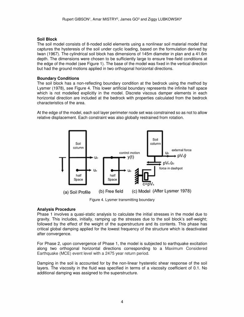
Soil Block The soil model consists of 8-noded solid elements using a nonlinear soil material model that captures the hysteresis of the soil under cyclic loading, based on the formulation derived by Iwan (1967). The cylindrical soil block has dimensions of 145m diameter in plan and a 41.6m depth. The dimensions were chosen to be sufficiently large to ensure free-field conditions at the edge of the model (see Figure 1). The base of the model was fixed in the vertical direction but had the ground motions applied in two orthogonal horizontal directions. Boundary Conditions The soil block has a non-reflecting boundary condition at the bedrock using the method by Lysmer (1978), see Figure 4. This lower artificial boundary represents the infinite half space which is not modelled explicitly in the model. Discrete viscous damper elements in each horizontal direction are included at the bedrock with properties calculated from the bedrock characteristics of the area. At the edge of the model, each soil layer perimeter node set was constrained so as not to allow relative displacement. Each constraint was also globally restrained from rotation.
Figure 4. Lysmer transmitting boundary
Analysis Procedure Phase 1 involves a quasi-static analysis to calculate the initial stresses in the model due to gravity. This includes, initially, ramping up the stresses due to the soil block’s self-weight; followed by the effect of the weight of the superstructure and its contents. This phase has critical global damping applied for the lowest frequency of the structure which is deactivated after convergence. For Phase 2, upon convergence of Phase 1, the model is subjected to earthquake excitation along two orthogonal horizontal directions corresponding to a Maximum Considered Earthquake (MCE) event level with a 2475 year return period. Damping in the soil is accounted for by the non-linear hysteretic shear response of the soil layers. The viscosity in the fluid was specified in terms of a viscosity coefficient of 0.1. No additional damping was assigned to the superstructure.
Rupert GIBSON1, Amar MISTRY2, James GO3 and Ziggy LUBKOWSKI4
5
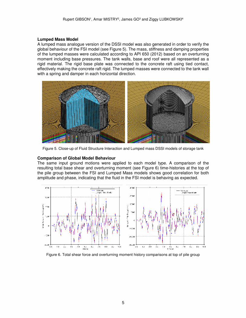
Lumped Mass Model A lumped mass analogue version of the DSSI model was also generated in order to verify the global behaviour of the FSI model (see Figure 5). The mass, stiffness and damping properties of the lumped masses were calculated according to API 650 (2012) based on an overturning moment including base pressures. The tank walls, base and roof were all represented as a rigid material. The rigid base plate was connected to the concrete raft using tied contact, effectively making the concrete raft rigid. The lumped masses were connected to the tank wall with a spring and damper in each horizontal direction.
Figure 5. Close-up of Fluid Structure Interaction and Lumped mass DSSI models of storage tank
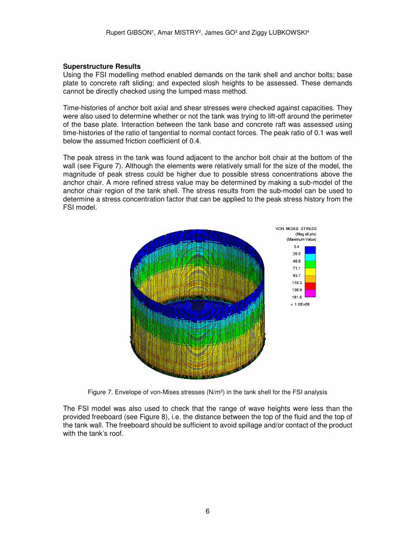
Comparison of Global Model Behaviour The same input ground motions were applied to each model type. A comparison of the resulting total base shear and overturning moment (see Figure 6) time-histories at the top of the pile group between the FSI and Lumped Mass models shows good correlation for both amplitude and phase, indicating that the fluid in the FSI model is behaving as expected.
Figure 6. Total shear force and overturning moment history comparisons at top of pile group
Rupert GIBSON1, Amar MISTRY2, James GO3 and Ziggy LUBKOWSKI4
6
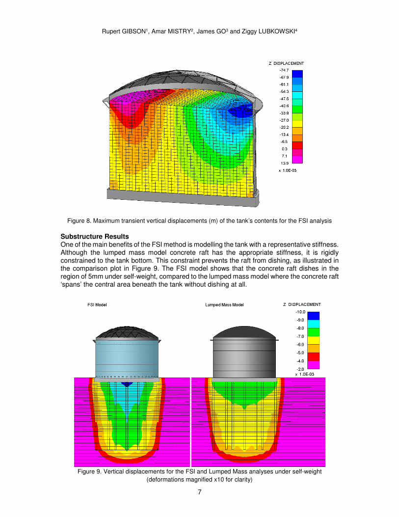
Superstructure Results Using the FSI modelling method enabled demands on the tank shell and anchor bolts; base plate to concrete raft sliding; and expected slosh heights to be assessed. These demands cannot be directly checked using the lumped mass method. Time-histories of anchor bolt axial and shear stresses were checked against capacities. They were also used to determine whether or not the tank was trying to lift-off around the perimeter of the base plate. Interaction between the tank base and concrete raft was assessed using time-histories of the ratio of tangential to normal contact forces. The peak ratio of 0.1 was well below the assumed friction coefficient of 0.4. The peak stress in the tank was found adjacent to the anchor bolt chair at the bottom of the wall (see Figure 7). Although the elements were relatively small for the size of the model, the magnitude of peak stress could be higher due to possible stress concentrations above the anchor chair. A more refined stress value may be determined by making a sub-model of the anchor chair region of the tank shell. The stress results from the sub-model can be used to determine a stress concentration factor that can be applied to the peak stress history from the FSI model.
Figure 7. Envelope of von-Mises stresses (N/m2) in the tank shell for the FSI analysis
The FSI model was also used to check that the range of wave heights were less than the provided freeboard (see Figure 8), i.e. the distance between the top of the fluid and the top of the tank wall. The freeboard should be sufficient to avoid spillage and/or contact of the product with the tank’s roof.
Rupert GIBSON1, Amar MISTRY2, James GO3 and Ziggy LUBKOWSKI4
7
Figure 8. Maximum transient vertical displacements (m) of the tank’s contents for the FSI analysis
Substructure Results One of the main benefits of the FSI method is modelling the tank with a representative stiffness. Although the lumped mass model concrete raft has the appropriate stiffness, it is rigidly constrained to the tank bottom. This constraint prevents the raft from dishing, as illustrated in the comparison plot in Figure 9. The FSI model shows that the concrete raft dishes in the region of 5mm under self-weight, compared to the lumped mass model where the concrete raft ‘spans’ the central area beneath the tank without dishing at all.
Figure 9. Vertical displacements for the FSI and Lumped Mass analyses under self-weight
(deformations magnified x10 for clarity)
Rupert GIBSON1, Amar MISTRY2, James GO3 and Ziggy LUBKOWSKI4
8
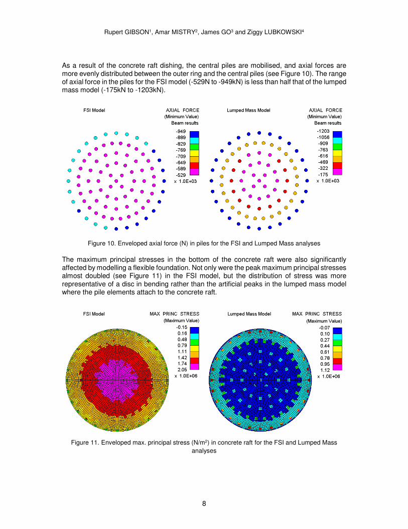
As a result of the concrete raft dishing, the central piles are mobilised, and axial forces are more evenly distributed between the outer ring and the central piles (see Figure 10). The range of axial force in the piles for the FSI model (-529N to -949kN) is less than half that of the lumped mass model (-175kN to -1203kN).
Figure 10. Enveloped axial force (N) in piles for the FSI and Lumped Mass analyses
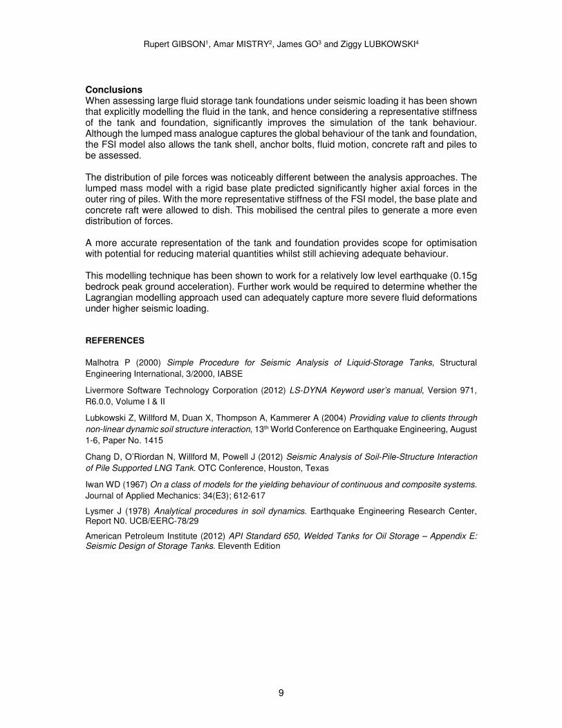
The maximum principal stresses in the bottom of the concrete raft were also significantly affected by modelling a flexible foundation. Not only were the peak maximum principal stresses almost doubled (see Figure 11) in the FSI model, but the distribution of stress was more representative of a disc in bending rather than the artificial peaks in the lumped mass model where the pile elements attach to the concrete raft.
Figure 11. Enveloped max. principal stress (N/m2) in concrete raft for the FSI and Lumped Mass
analyses
Rupert GIBSON1, Amar MISTRY2, James GO3 and Ziggy LUBKOWSKI4
9
Conclusions When assessing large fluid storage tank foundations under seismic loading it has been shown that explicitly modelling the fluid in the tank, and hence considering a representative stiffness of the tank and foundation, significantly improves the simulation of the tank behaviour. Although the lumped mass analogue captures the global behaviour of the tank and foundation, the FSI model also allows the tank shell, anchor bolts, fluid motion, concrete raft and piles to be assessed. The distribution of pile forces was noticeably different between the analysis approaches. The lumped mass model with a rigid base plate predicted significantly higher axial forces in the outer ring of piles. With the more representative stiffness of the FSI model, the base plate and concrete raft were allowed to dish. This mobilised the central piles to generate a more even distribution of forces. A more accurate representation of the tank and foundation provides scope for optimisation with potential for reducing material quantities whilst still achieving adequate behaviour. This modelling technique has been shown to work for a relatively low level earthquake (0.15g bedrock peak ground acceleration). Further work would be required to determine whether the Lagrangian modelling approach used can adequately capture more severe fluid deformations under higher seismic loading. REFERENCES
Malhotra P (2000) Simple Procedure for Seismic Analysis of Liquid-Storage Tanks, Structural
Engineering International, 3/2000, IABSE
Livermore Software Technology Corporation (2012) LS-DYNA Keyword user’s manual, Version 971,
R6.0.0, Volume I & II
Lubkowski Z, Willford M, Duan X, Thompson A, Kammerer A (2004) Providing value to clients through
non-linear dynamic soil structure interaction, 13th World Conference on Earthquake Engineering, August
1-6, Paper No. 1415
Chang D, O’Riordan N, Willford M, Powell J (2012) Seismic Analysis of Soil-Pile-Structure Interaction
of Pile Supported LNG Tank. OTC Conference, Houston, Texas
Iwan WD (1967) On a class of models for the yielding behaviour of continuous and composite systems.
Journal of Applied Mechanics: 34(E3); 612-617
Lysmer J (1978) Analytical procedures in soil dynamics. Earthquake Engineering Research Center, Report N0. UCB/EERC-78/29
American Petroleum Institute (2012) API Standard 650, Welded Tanks for Oil Storage – Appendix E: Seismic Design of Storage Tanks. Eleventh Edition