Embed Size (px)
Citation preview
N86-14095
FLUORINE DISPOSAL
By: Allen Rakow
A preliminary design of an F2 disposal system for HELSTF is •
presented here along with recommendations on operational policyi
and identification of potential operational problems. The
_ analysis is based on sizing a system to handle two different
modes of the HELSTF Fluorine Flow System (one operational and
one catastrophic). This information should serve both as a
guide to a final detailed design for HELSTF as well as a
: reference for subsequent monitoring and/or modification of the
system which consists of a charcoal reactor followed by a dryt
soda lime scrubber.
Contents
A. HELSTF F2 Flow System - Disposal Design Criter'a
B. Literature Review
C. Analysis
D. Proposed System Designf
E. Recommendations
.r
19-16
1986004609-266
https://ntrs.nasa.gov/search.jsp?R=19860004626 2020-04-15T08:07:27+00:00Z
: \
A. HELSTF F2 FLOW SYSTEM - DISPOSAL DESIGN CRITERIA
Two cases were consiOered in the Oesign of the waste disposal
system:
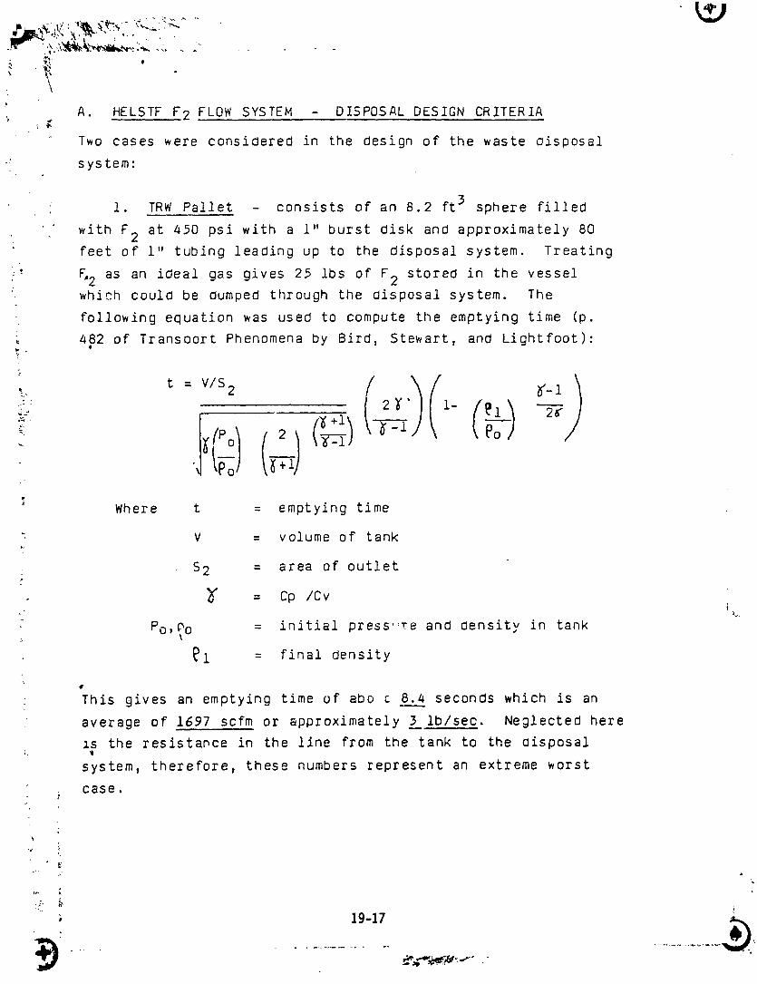
i. TRW Pallet - consists of an 8.2 ft3 sphere filled
with F 2 at 450 psi with a 1" burst disk and approximately 80
feet of i" tubing leading up to the disposal system. Treating
' Fo2 as an ideal gas gives 25 lbs of F 2 stored in the vessel
which could be dumped through the Oisposal system. The
following equation was used to compute the emptying time (p.
482 of Transoort Phenomena by Bird, Stewart, and Lightfoot)"@
I ff e1 28-
•1i
Where t = emptying time
" V = volume of tank
• S 2 = area of outlet
= Cp /C vi
Po,_a = initial press"re anc_ Oensity in tank
_i = final density
q
This gives an emptying time of abo _ 8.4 seconds which is an
average of 1697 scfm or approximately 3 ib/sec. Neglected here
xs the resistance in the line from the tank to the Oisposal;. _@
system, therefore, these numbers represent an extreme worst
J case.
i'
,j i'
19-17
1986004609-267
2. Aspirator - Composition of the F2-N 2 mixturethrough the aspirator will vary; however, a 50-50 mixture by
volume, at 36 scfm will be taken as a typical starting ._.l
condition. At .03 ibm F2/sec t,11s would be 1/lO0 of the
F2 rate in the catastrophic case above.
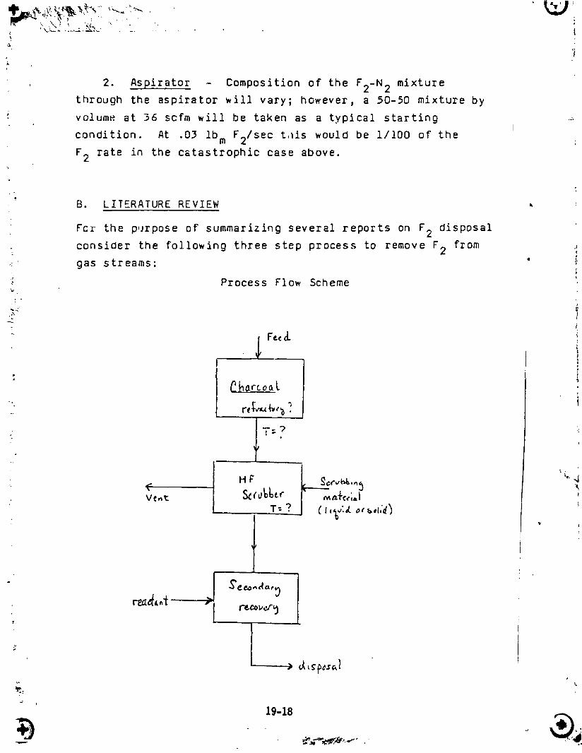
B. LITERATURE REVIEW
For the purpose of summarizing several reports on F2 disposal
• consider the following three step process to remove F2 from .,
__.- gas streams: " ",.
." Process Flow Scheme
•'>z_ !
|
: _Charcoal
-.-
IT=? ::
Ve_t Sdo_l_er _ _. I
t "
19-18
1986004609-268
2',- , ""
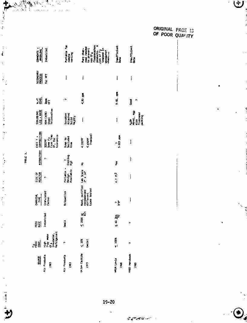
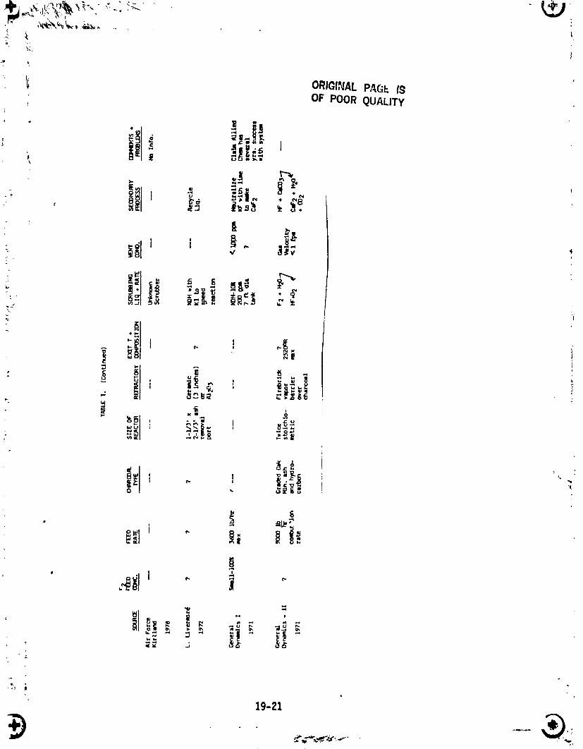
_ Table I is a summary of various designs and operating
_I conditions. Note that KOH is a popular scrubbing fluid for
'{. HF. This is probably due to its greater solubility in H20
_ then NaOH as well as a marked difference in solubility of KF '_'
' vs. NaF in H20 as sho_n in Table II. KOH would have a
., definite advantage over NaOH since a scrubber could run longer
J
2-
•-: Table II. Solubility g/lO0 ml H20
_ ... , NaOH 42 °
- KOH 97 ° ;• 1
NaF 4.2218 ",
._& KF 92.3 -_" @- i
f,
_Handbook of Chemistry & Physics
!_.-
on recycled liquid before an insoluble salt woul_ form. There
are several disadvantages of a KOH scrubber; however, which
would make a solid system.,more desirable. First., the scrubbing
liquid would have to be treated in a secondary step to remove
KF. Secondly, the freezing point of KO_ would probably be in
• the 20-30°F range which could cause problems since the system _4_
_ili be outdoors. Third, a packing material _ould be desirable
to effect mass transfer, and lastly liquid handling equipment
_oulO be necessary. If a liquid system could be avoided this
_oulO be a great advantage.
19-19
1986004609-269
; ORIGINALPACE '_";,.3
OF POORQUP_ITY
"1
• 1%202.
+J -®,
1986004609-270
i
" t ORIGINALPAC_F..ISOF POORQUALITY
• _1_ _ _,. ._
i
19-Zl
_ .'_ .-,,'_ ' -,,_,_
1986004609-271
B
L
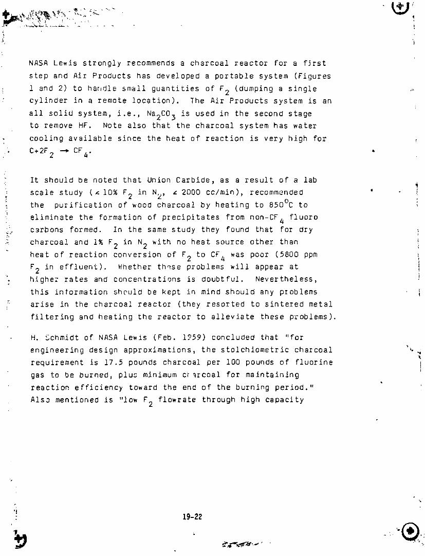
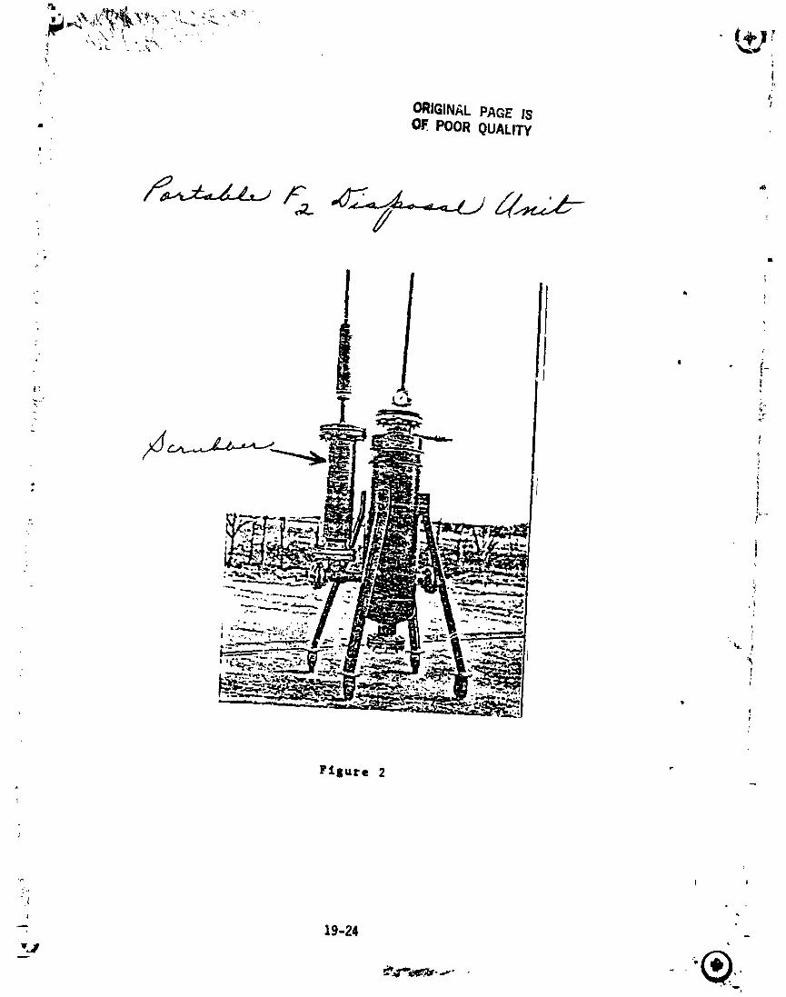
NASA Lewis strongly recommends a charcoal reactor for a first
step and Air Products has developed a portable system (Figures
i an_ 2) to handle small guantities of F2 (dumping a single ,,_• cylinder in a remote location). The Air Products system is an
all solid system, i.e., Na2CO 3 is used in the second stageto remove HF. Note also that the charcoal system has water
cooling available since the heat of reaction is very high for
o C+2F --_CF • ,2 4"
It should be noted that Union Carbide, as a result of a lab
' scale study (z i0_ F2 in N2, z 2000 cc/min), recommended "_. the purification of wood charcoal by heating to 850% to i
eliminate the formation of precipitates from non-CF 4 fluoro
___ carbons formed. In the same study they found that for dry i
s charcoal and i% F2 in N2 with no heat source other than _I
heat of reaction conversion of F2 to CF4 was poor (5800 ppm _
F2 in effluent). Whether these problems will appear at I
: higher rates and concentrations is doubtful. Nevertheless,
this information should be kept in mind should any pzoblems
arise in the charcoal reactor (they resorted to sintered metal
filtering and heating the reactor to alleviate these problems).
H. Schmidt of NASA Lewis (Feb. 1759) concluded that "for
engineering design approximations, the stolchiometric charcoal "_
requirement is 17.5 pounds charcoal per lO0 pounds of fluorine
gas to be burned, plus minimum c[arcoal for maintaining
reaction efficiency toward the end of the burning period."
Also mentioned is "low F2 flowrate through high capacity
,'|
- 19-22
L ',P@
_.,IT_.',..-_-"'_;""
1986004609-272
'",_ure I
- 19-23
1986004609-273
ORIGIN/_LPAGE IS• OF. POOR QUALITY
F£gure 2
-- 19-24 _
_p
1986004609-274
,_ "j
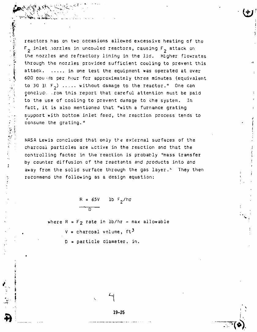
•_. reactors has on two occasions allowed excessive heating of the
, F inlet ,_ozzles in uncouled reactors, causing F 2 attack on
,_ the nozzles and refractory lining in the lid. Higher flowrates
through the nozzles provided sufficient cooling to prevent this '_
i attack ...... in one test the equipment was operated at over600 pou,ds per hour for approximately three minutes (equivalent
_" to 30 i_ F2) ..... without damage to the reactor." One can
...._ concl,J_, .tom this report that careful attention must be paidv
to the use of cooling to prevent damage to Lhe system. In
. fact, it is also mentioned that "with a furnance grating _,
•_ support with bottom inlet feed, the reaction process tends to
; consume the grating." i
_ : NASA Lewis concluded that only tb_ ex'Cernal surfaces of the
_ charcoal particles are _ctive in the reaction and that the }
controlling factor in the reaction is probably "mass transfer i
by counter diffusion of the reactants and products into and
away from the solid surface through the gas layer." They then
t recommend the following as a design equation:#
--, R = 65V lb F2/hr
D
, where R = F 2 rate in ib/hr - max allowable
, V : charcoal volume, ft 3
' D = particle diameter, in.y'
I,
't ,
t
............................................ "(.3
1986004609-275
w._ , _L_,_ , , . , : . __, i
i '[
-j
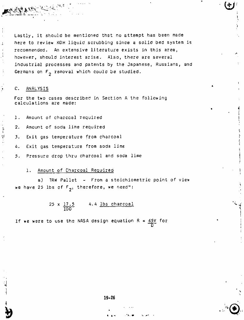
Lastly, it should be mentioned that no attempt has been made
here to review KOH liquid scrubbing since a solid bed system is
recommended. An extensive literature exists in this area,
' however, should interest arise. Also, there are several
industrial processes and patents by the Japanese, Russians, and
Germans on F2 removal which could be studied.
&
C. ANALYSIS
For the two cases describe_ in Section A the followingcalculations are made:
• 4I
I. Amount of charcoal required !7
_ 2. Amount of soda lime required
3. Exit gas temperature from charcoal _}
4. Exit gas temperat'Jre from soda lime q
5. Pressure drop thru charcoal and soOa lime i!
i. Amount of Charcoal Required !
a) TRW Pallet - From a stoichiometric point of view
we have 25 ibs of g2, therefore, we need": i
25 x 17.5 4.4 ibs charcoal _4i00
If we were to use the NASA design equation R = 65V forD
19-26
1986004609-276
i t
3/8" charcoal and a rate of 1697 scfm (10,780 ib/hr) we'd need
_. 62 ft 3 of charcoal. Considering a void volume of .4 and a, 3
charcoal density of 12 ib/ft this would be 446 ibs of
! _ charcoal.
_ We can also use the following equation to compute the volume of
_ charcoal required to achieve a particular exit concentration of
' F,2 from the bed:
OfYA1• V = G i
: _ akgC \ YA2]7 .-
t
j_._ where V volume of bed ft 3
_ _ G = molar rate of gas, ib molesmin
a = effective surface area/vol of bed, ft2
kg = ma_s transfer coefficient, ft/min ,
6 = molar density of gas = P = ib molesRT 3ft
YAI = mole fxn of F2 into reactorP
I ,
YA2 = mole" fxn of F2 out of reactor
@
19-27
1986004609-277
, This equation is based on steady isothermal flow and diffusion
control, i.e., as soon as the F2 reaches the charcoal surface
it reacts instantaneoulsy with the carbon on the surface only.
For the TRW pallet case, YAI = I, G = 4.73 ib mole, C = P =min RT
14.7 psi x 144 = .0007 lb moles assuming a max T of 2000°R in
: 1544 (2000°R) ft3
the reactor, a = 115 ft2 for 3/8" particles
ft3
_ and set YA2 = 1 ppm = lO6
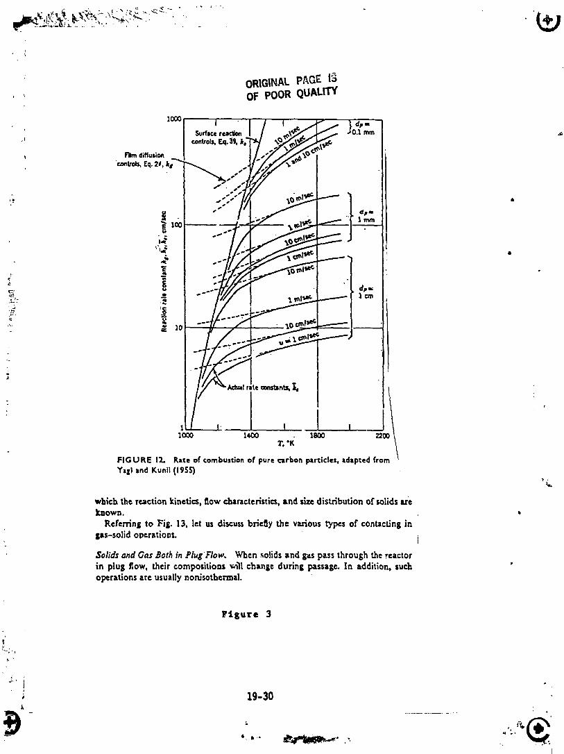
_. From Figure 3 we can take kg to be i0 cm/sec or 19.2 ft/min.
so V = 4.73 in 106• (115) (19.7) (.0007)
3or V = 41.2 ft (not drastically different from the
NASA design equation)
This would be 297 lbs of charcoal.
b) Aspirator
l) NASA Design:
18 scfm x 1 ib mole x GO min x 38 lb = 114 ib _
)59 ft) hr lb mole hr
V = 114 x 3 = .65 ft) (4.7 ib charcoal)
19-28
1986004609-278
\ 2) Diffusion Control Equation:
YA1 .5, G = .i lb molemin
y kg = 2 cm/sec = 3.94 ft/min
V - .1 in .5
/' 115 (3.54) (.0007) i0 -6:
V = 4.13 ft3 (30 ib charcoal)
_ , _....................... .19-29 _i
i986004609-279
/
1 I 1 I
2_ 1_ r.'K" 1
FIGURE 17.. Rate of combustion of pure c_rbon particles, adapted f"fall and Kunll (1955)
which the reactionkinetics,flow characteristics,and sizedistributionor solidsWeknown.
Ken'erringto Fig. 13, let us discuss briegy the various types of conucdng ingas-solid operations.
Solids and Gas3orb in PlugFlow. When,_olidsand g',_spassthroughthe reactorin plug flow, their compositions_'ll changeduring passage.In addition,suchoperations arc usually non.lsothcrma|.
Figure 3
i
19-30
] 986004609-280
J
i' 2. Amount of SoOa Lime Required_ '1i a) TRW Pa!lett - Assuming 1096 HF out of the charcoal
r
,; due to the residual H20 in the charcoal and the same modelo (diffusion control) as the charcoal then:
! YA1 = .1 ,
" ; 2 !a = 445 ft for 1/8" soda lime particles
ft3
G : 2.36 r
Since there are half as many moles of gas (C+2F2-*CF 4) then: l
i"2;
_ V = 2 36 In 1 : {
-_ 445 (19 7) ( 0007) 10-6 'L- f
V = 4.42 ft (at a density of 125 ibs and a void ¢
• ft3
; 'fraction of .4 this would be 33___Iibs of soda lime : )
b) Aspirator !l
4.02 x 4.13 = .44 ft3-_ 33 ibs of soda lime !41.2 :_,
3, Exit Gas T From Charcoal _ ;
a) TRW Pallet - We'll assume that an equilibrium is festablished whereby the charcoal temperature rises to that of I
the exit gas and the system is aOiabatic (no transfer through i
walls ). I
i '
19-31 i"
4. &_, I r, _ " _ ' -" .
1986004609-281
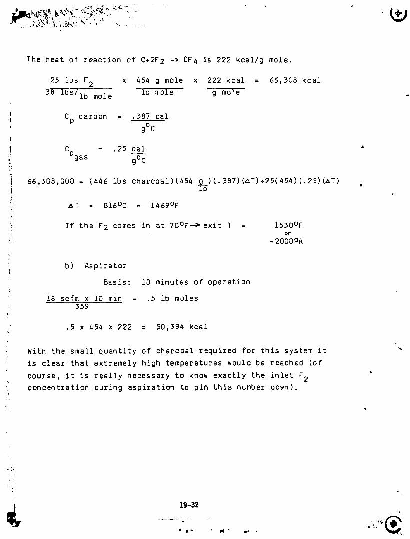
The heat of reaction of C+2F2 -_ CF4 is 222 kcal/g mole.
25 Ibs F2 x 454 g mole x 222 kcal : 66,308 kcal
38 ibS/ib mole ib mole g mo_e
! Cp carbon = 387 cal, g° CI
I C = .25 cal
Pgas go'_
_ 66,308,000 = (446 Ibs charcoal)(454 _b) (.387) (z:T)+25(454)(.25) (_T) •
:t• ._T : 816°C : 1469°F
"_ If the F2 comes in at 70°F-_ exit T : 1530OF_. 01"
-_-, .. 2000oR
• b) Aspirator
Basis: i0 minutes of operation
18 scfm x 10 rain = .5 lb moles359
1.
.5 x 454 x 222 = 50,394 kcal
1
With the small quantity of charcoal required for this system it
is clear that extremely high temperatures would be reachea (of
course, it is really necessary to know exactly the inlet F2?
concentration during aspiration to pin this number down).
t°.
, pq
':'i
19-32
1986004609-282
| , _. \ ,
!
, J,I
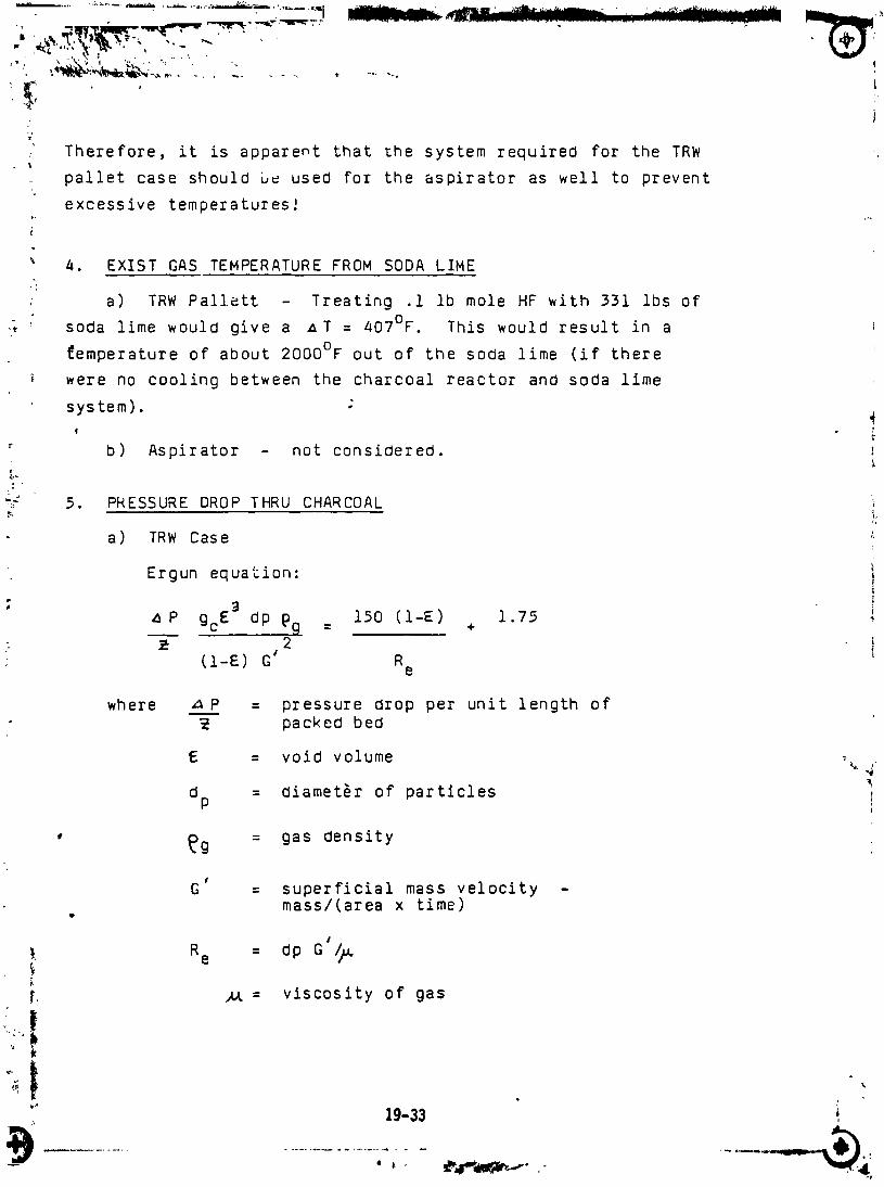
;: Therefore, it is apparent that _he system required for the TRW
pallet case should b_ used for the aspirator as well to prevent
excessive temperatures:
4. EXIST GAS TEMPERATURE FROM SODA LIME
. a) TRW Pallett - Treating .1 ib mole HF with 331 lbs of
; soda lime would give a _T = 407°F. This would result in a
_emperature of about 2000°F out of the soda lime (if there
were no cooling between the charcoal reactor and soda lime
system).
b) Aspirator - not considered.r
":- 5. PRESSURE DROP THRU CHARCOAL
a) TRW Case _
Ergun equation: I
: g 1 75 iP gcE dp pg : 150 (l-E) + .
- _- 2(l-E) G_ R i
e
where _ P = pressure drop per unit length ofpacked bed
E : void volume _ 4
dp = diameter of particles
, _g = gas density
¢
G = superficial mass velocity -mass/(area x time)
t
#
}, Re = dp G /_
[. _ = viscosity of gas
t
" 19-33
1986004609-283
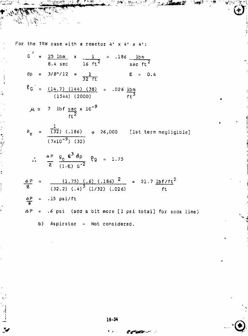
, For the TRW case with a reactor 4' x 4' x 4':
J
G : 25 ibm x 1 = .186 ibm
8.4 sec 16 ft 2 see ft 2
i dp : 318"112 : 1 E : 0.4'_ 32 ft
_G = (14.7) (144) (38) = .026 Ibm
" (1544) (2000) ft 3
_t _- 7 ibf se___cx i0 -9 :
ft2
Re = (32) (.186) -. 26,000 [ist term negligible]mr
_._ (7xlO -9) (32) iT- !
• "_P gc E3 _p _g = i 75(i-_) G '2 !
p
, !
z_P = (1.75) (.6) (.186) 2 = 21.7 ibf/ft 2
- _ (32.2) (.4) 3 (1/32) (.026) ft
mp = .15 psi/ft i
z_P : .6 psi (add a bit more [1 psi total] for soda lime)
b) Aspirator - Not considered.
' 19-34 _
1986004609-284
D. PROPOSED SYSTEM DESIGN
i. Charcoal Reactor - A volume of 62 ft 3 (446 lbs of
wood charcoal, 3/8" diameter) is required. The General
Dynamics Sycamore Canyon Reactor (GDSCR) would be a suitable
design. It is basically a cylindrical furnace with a firebrick
floor, firebrick walls of 4-1/2 in. x 9 in. straights end
wedges, and a conical sheet metal hood. Since the GDSCR wasL
, d_signed for 528 cuft with 2 ft of ullage above ;he charcoal
the GDSCR could be scaled Oown by 1/3 _n cross-sectional area
and i/3 in height to give the required HELSTF volume. The
inlet and outlet lines will of course be smaller but the inlet
should be equipped with cooling water and the polyethylene
isn't needed since the HELSTF system will be used for normalD
: operation. Attached is a description bf the GDSCR system.
32. Soda Lime Scrubber - A volume of 4.42 ft (331 lbs) !
is required. Fischer Chemical (Wendy 800/527-5920) can supply
", 14 kg containers (6-12 mesh) at $135 per container. This ' 'i '
amount should be sufficient for each aspiration. The design
for this system could be the same as the GDSCR only scaled down i
to the smaller volume.
19-35,I
1986004609-285
ORIGINALPAGEISOF.POORQUAUTY
GDSCR SYSTEM DESCRIPTION
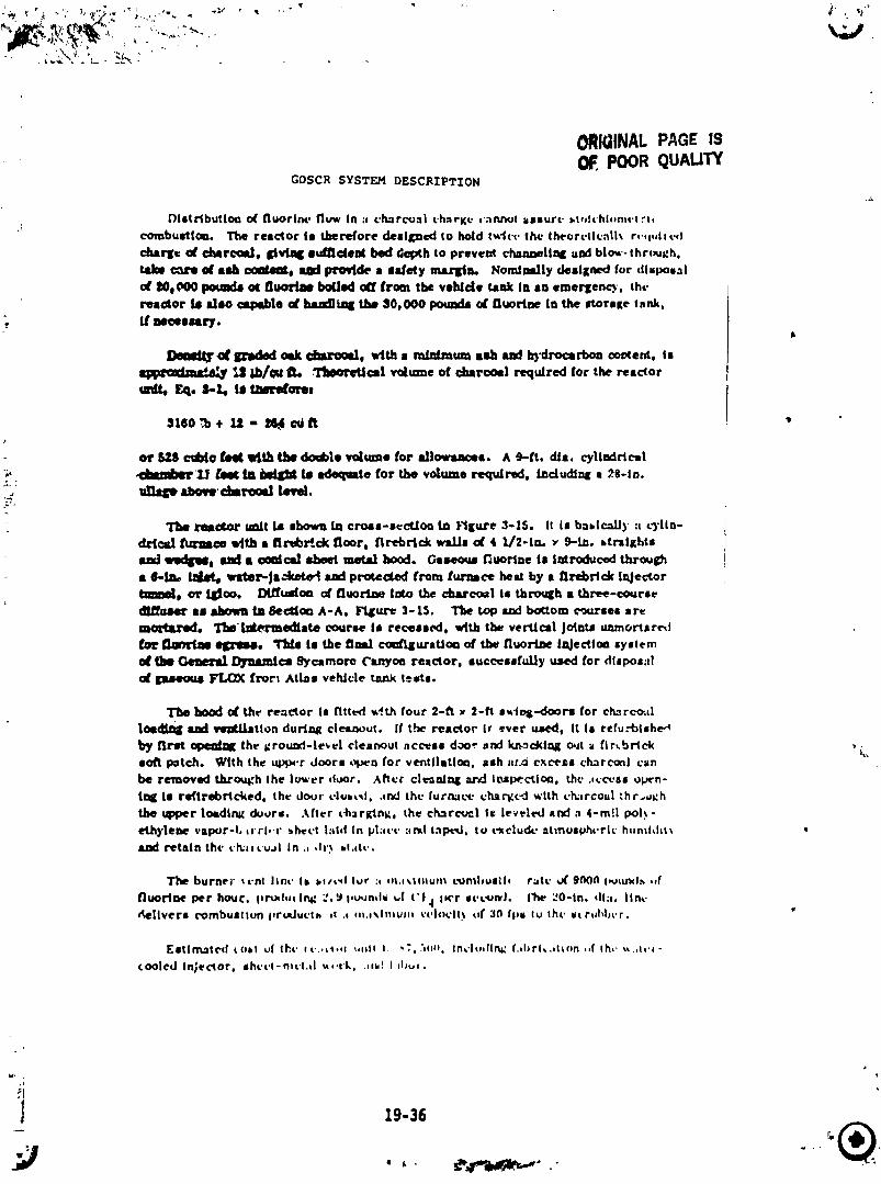
i')istrlbutlot_ o( fluorine. I'luw In ;, cl_rconi chnrKc _-aru_t lssurc bl,H¢'hl-m,.t rt,
combustion. The re=_or 10 therefore designed to hold t_l(.l, the Iheorrt|c_lk r4",l,llvfl
c_rg¢ (d' cl_rc_Id, I_vblg Ilul_ldellt bed depth to prevent oh•lug•ling add blo_'-thr(_gh,
t_e _ of ash _0 _ proud• • s_ety mArlitJL Noml_lly deslgm,d for disposal_OoPO0pounds o¢ tlu_ise boiled off from •be vehicle tank It, so emerlen_, thv
reactor is also csp_lo al' Juu_iag the $0,000 pound8 _ fluorine In the stortKe tank,ff necessary.
II_m_l_,_ _ _ dm'u_, with • minimum ash and h_lrocarbon m_e_, is
=p_=dz=d_ ',dllib/m= li_ .'[teotetlc=l vdmne of charcoal required for the reactorEq. b._, IS t/m_mt
or II_S cubic _J4_,Mth _ double to/me for aJlosnmcol. A 9--l't, die. cylindrical
> 4:t_mberl_ _e_ bl _ Is tdoquate for _ volume required, l_dudfn_ • 28-1n.
,_ u_Ze abovlcbsre,_ I_wl.
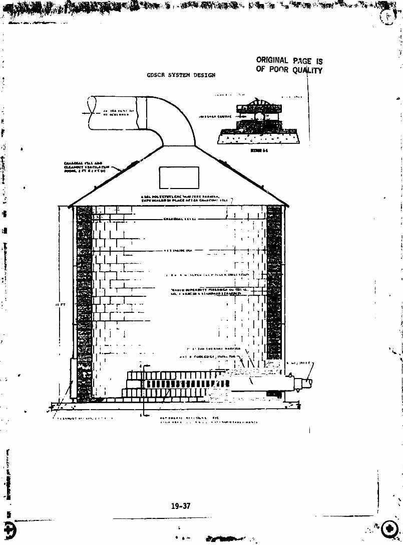
reactor u_tt is shown in croas-sccLtoa tn F_igure 3-15. It is baiical])' t cylln-
d.r/¢_ fhl"smoo w/th a flrebre.ck floor, firebrick walls o( 4 1]2-[m x 9-t-. straights
mud _mdr_l_t and a conical 8beet metal hood. Geseo_ fluorine t• Introduced thr_J_• _-_ ta_ wl_er-|ackete_ and prgtec_e4 from furnace best by • firebrick Injectortz_n01, or II_OO, Dlffu_/o_ c_ fluorine late the d_rcoel Is thro_h • three-course
dlHmlmrassbosmtnSectlc_A-A, Ft_ure3-IS. Thetopa_lbo_omc,mrsesaremothLred, Tl__ed/ate co_rse l• rece•sed, with the vertical )o_nt_ uamor_ared
_lt t_mr_a8 _. _ is the final c_'lKuraUcel of the fluort_ laJecttc_ system
O__ _ J[_lulmlc= 9),¢_more C_n_oe reactor, successfully used for diipos;llC_ I FL_0_ lrorl Alias vehicle ta_X tests.
The hood c_ the reactor Is fitted _th four 2-fl x 2-It s_e_-.doors for ch._rc-_al
|Oedl_ _ verltJ.latlon durst•{cleu_ut. If the reactorIr_ver uJed, ItIs refu.'-btshea
by first (qXu_d_g the grou_l-le_el cleanout access doe." .ridk_ckl_g out a fir_br/ck ,_,_soft p=teh. With the uplx.r doors _q_n for ventllstIo=, ash lir._i excels c.h_rcoctIcanbe removed through the Ic_.er duor. .4tier clt-_l_ arid i_l_ctlo_, the .,c.ct.si ol_n-
tl_ Is re(lrebrlcked, the dour c'lui_l, .,rid the furn_c_ ch_t_c_ with cl_,rcoul "hr,.,_:h
the ;_er lot=din= doors. After ¢4_ar_ng, the ch=rctml li lrveted _nd a 4-m!l pol._-
ethylene Vlil_r-L ll'rl,.i" =heft hid In pl:iiT :tell tapt_l, to t'xchJI_L' atmosphi'rlc hlinlillil_ tretain thc l.h_il l.l.iji II1 .i ,11"$.I.itl,.
The bur•el" ll.lll Ilrll. li il#l_l lur ;i lil.i%llliUlit i._Jmllullll r_itl" _ t0_111 ll_lu_l_ ,if
Nuorllle Per houc, lir_hlllrlll 7,_J i,u_rllll _l ('1. l I_'r svi_rii, I?_ 20-111, dl.i. lira.
delivers combuillon llr_Jut'th iI .i nl.i.%lnlwlli v¢.lol'll% lif 3(I fill to Iht" it rllhllcr.
[illm.llc'd tllil iJt ll_.l, ll..,t_,,I i,iiII i. _G, .'lilll, Irlclt, lll%i_ f.llirl_.dion ,,fih,. _.,li.i-
tooled Illle_0r _ ihi, l,l-nll'l.il lll.t'k, .ill! I illwi.
, 19-36
_ .I
1986004609-286
j19-37
1986004609-287
-_T _ t,',x"_': ._, ' *
• 4 , B
E. RECOMMENDATIONS
i. Measure F2 and HF concentrations in effluent during
, test run to confirm efficiency of syste_ (temperature would ._
also be useful).J ,
2. Use extreme caution in cleaning and replenishi,lg system(after lO aspirations) sincc fluorine could be present.
?
@
3. ShoulO cooling water be unevailable make sure that F2
metal inlet tube is replaced with ._:efractory.
@
4. Same approach should b6 taken with soda lime scrubber. _:i
L. 5. System requires 3,'8" woo_ charcoal, shoul_ particle, °
_e entrainment become a problem consider adding a filter between
_: the charcoal an_ so_a lime reactors.
i
b.
_t 19-38
, _w
1986004609-288


![Sulfur - fluorine bond in PET radiochemistry...Sulfur-[18F] fluorine radiolabelled reagents and compounds [18F]Sulfonyl fluorides The first account of the sulfur-[18F] fluorine bond](https://img.pdfslide.net/doc/110x75/6132f51ddfd10f4dd73ac7b8/sulfur-fluorine-bond-in-pet-radiochemistry-sulfur-18f-fluorine-radiolabelled.jpg)