Embed Size (px)
Citation preview

December 2-5, 2003 ◊ MGM Grand Hotel Las Vegas
Flushing Out Your Plumbing Design!
Speaker : Mike Kotanian – Autodesk, Inc.
BD13-2 In this session, we will focus specifically on the Autodesk® Building Systems Plumbing tools, from one-line riser diagrams and isometrics to detailed domestic and sanitary plumbing layouts. Understand how to leverage the 3D content and intelligence of Autodesk Building Systems technology to produce more accurate and better-coordinated drawings.
About the Speaker: Mike brings 12 years of AEC industry experience to Autodesk's team of application engineers. He received a Masters of Architecture degree from the University of Colorado, receiving a Tau Sigma Delta award for his achievement. After practicing architecture throughout the western United States, Mike spent 2 years as a consultant helping clients customize and implement Autodesk® Architectural Desktop and other Autodesk® based solutions. Mike is currently working with the entire Building Solutions Division product line to assist Autodesk® customers and resellers throughout the United States.

Flushing Out Your Plumbing Design!
2
Flushing Out Your Plumbing Design! Autodesk University Session: BD13-2 Tuesday, December 2nd, 2003 - 3:30 pm - 5:00 pm Presented By Mike Kotanian : Building Solutions Division Applications Engineer – Autodesk, Inc. Course Outline:
• Lesson 1.0: Adding Fixtures o Part Catalog and Part Placement o Fixture Unit Tables o Pre-Defined Elevations
• Lesson 2.0 Adding Schematic Pipe o Connect various Plumbing Fixture into a Domestic Cold Water System
• Lesson 3.0 Adding Schematic Pipe Fittings
o Adding Gate Valves o Adding Reducers
• Lesson 4.0 Creating Waste Systems
o Connect various Plumbing Fixtures into a Sanitary Waste System o Modify Fittings o Adding Cleanouts
• Lesson 5.0 Sizing supply Systems
o Pipe Sizing Tables o Sizing the Source Pipe o Sizing the Main Branch o Sizing Individual Pipe
• Lesson 6.0 Creating Isometric Diagrams
o Adding a Lateral to a Sanitary Waste Line o Adding a Sink Trap o Adding a Takeoff for Floor Drains
• Q & A and Evaluations
Please note: The corresponding datasets mentioned in the following documentation can be located on the provided Autodesk Building Systems 2004 Workshop CD provided to you during this course.
From opening Proj. Brow. Scrn: Introduce the class Outline Objectives ABS Workshop Matl. Disk available to ALL Discuss 6 key topics (SEE PPT slide) Walk-Thru the simple install procedure Show Install screen, content, avi’ Profile Swap from ABS to Plumbing Talk about why…
Flushing Out Your Plumbing Design!
3
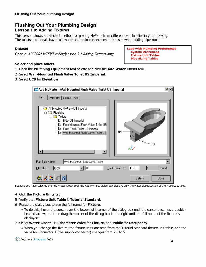
Flushing Out Your Plumbing Design! Lesson 1.0: Adding Fixtures This Lesson shows an efficient method for placing MvParts from different part families in your drawing. The toilets and urinals have cold water and drain connections to be used when adding pipe runs. Dataset Open c:\ABS2004 WTE\Plumbing\Lesson 3-1 Adding Fixtures.dwg Select and place toilets 1 Open the Plumbing Equipment tool palette and click the Add Water Closet tool. 2 Select Wall-Mounted Flush Valve Toilet US Imperial. 3 Select UCS for Elevation
Because you have selected the Add Water Closet tool, the Add MvParts dialog box displays only the water closet section of the MvParts catalog. 4 Click the Fixture Units tab. 5 Verify that Fixture Unit Table is Tutorial Standard. 6 Resize the dialog box to see the full name for Fixture.
• To do this, hover the cursor over the lower-right corner of the dialog box until the cursor becomes a double-headed arrow, and then drag the corner of the dialog box to the right until the full name of the fixture is displayed.
7 Select Water Closet - Flushometer Valve for Fixture, and Public for Occupancy. • When you change the fixture, the fixture units are read from the Tutorial Standard fixture unit table, and the
value for Connector 1 (the supply connector) changes from 2.5 to 5.
Lead with Plumbing Preferences System Definitions Fixture Unit Tables Pipe Sizing Tables
Flushing Out Your Plumbing Design!
4
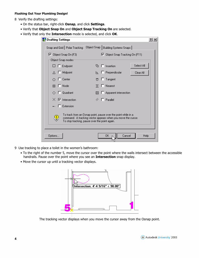
8 Verify the drafting settings: • On the status bar, right-click Osnap, and click Settings. • Verify that Object Snap On and Object Snap Tracking On are selected. • Verify that only the Intersection mode is selected, and click OK.
9 Use tracking to place a toilet in the women’s bathroom:
• To the right of the number 5, move the cursor over the point where the walls intersect between the accessible handrails. Pause over the point where you see an Intersection snap display.
• Move the cursor up until a tracking vector displays.
The tracking vector displays when you move the cursor away from the Osnap point.

Flushing Out Your Plumbing Design!
5
• Enter 18. • In the drawing, use the Compass to rotate the toilet to 0 degrees, and then click to place it.
10 Press ENTER to end the command. Select and place urinals 11 On the Plumbing Equipment tool palette, click the Add Urinal tool. 12 Select Urinal Stall US Imperial. 13 Verify that Elevation is UCS.
14 Click the Fixture Units tab. 15 Verify that Fixture Unit Table is Tutorial Standard, Fixture is Urinal, and Occupancy is Public. 16 Following the same procedure you have been using, add two urinals to the drawing.

Flushing Out Your Plumbing Design!
6
• Place the fixtures 18" from the stall partitions, as shown.
The urinals are placed in the drawing. 17 Press ENTER to end the command.
NOTE: You can calculate pipe sizing values at any time in the design phase of your project, even before you have added schematic pipe. On the MEP Common menu, click Plumbing > Sanitary Pipe Sizing Calculator, add known values, and press ENTER to calculate the pipe size. You can also size supply pipe using the Supply Pipe Sizing Calculator.
In this Lesson, you used the Plumbing Equipment tool palette to access individual sections of the MvParts catalog. Use this tool palette to insert several different types of parts. Use a filtered list, as you did in the previous Lesson, when you want to insert only one type of MvPart. Knowing when to use a filtered list instead of the full catalog can help you work more quickly and efficiently. In addition to working with part selection in this Lesson, you also continued using object snap points, object tracking, and the Compass for part placement.

Flushing Out Your Plumbing Design!
7
Lesson 2.0: Adding Schematic Pipe This Lesson shows how to add schematic pipe for the cold water system. Whenever you add schematic pipe, you specify its system, such as Domestic Cold Water. The system definition controls the display properties, layers, and default fittings used in the pipe run, as in the previous lesson when you created the Gas system definition. In this Lesson, you connect the toilets in the women’s bathroom to the main supply branch, starting with the cold water connection farthest from the source. The men’s bathroom has been done for you. Two changes have been made to the drawing to isolate the fixtures where the pipe will be drawn: the drawing area Autodesk® Building Systems 2004 Workshop Tutorials containing the fixtures has been enlarged, and some layers have been turned off to make it easier to connect the pipe. Dataset Open c:\ABS2004 WTE\Plumbing\Lesson 3-2 Adding Schematic Pipe.dwg Connect a domestic cold water pipe to a toilet 1 On the status bar, right-click Osnap, and click Settings. 2 On the Object Snap tab, click Clear All, and click OK.
TIP: Clearing object snaps and keeping Building Systems snaps enabled help to ensure the proper connection of segments.
3 Open the Plumbing tool palette and click the Add Schematic Pipe tool. 4 In the Add Schematic Pipes dialog box, select PVC Thermoplastic Pipe for Style.
• You do not need to specify values for System, Elevation, or Nominal Size because the values will be read from the connector when you select it in the drawing.
5 Beginning with the toilet nearest the top of the drawing, move the cursor over the back edge of the toilet until a Pipe Connector snap displays, and then click the snap.
6 In the Select Connector dialog box, select Connector 1: Cold Water, and click OK.

Flushing Out Your Plumbing Design!
8
NOTE: The Select Connector dialog box is displayed only when the connectors on a fixture are in the same plane.
7 Move the cursor over the Add Schematic Pipes dialog box. • Notice that values have been filled in for System, Elevation, and Nominal Size, based on the information read from the connector you selected.
8 Enter 9’ for Elevation because the supply piping for this sample project will be run between the first and second floors. 9 In the drawing, move the cursor toward the right at 0 degrees, and enter 48.
10 Move the cursor down to the bottom of the drawing at 90 degrees until a Pipe Curve Connector snap displays on the main supply branch. Click the snap to connect the pipe, as shown.

Flushing Out Your Plumbing Design!
9
The fixture farthest from the source is connected to the main supply branch. The elbow and tee fittings are inserted automatically.
Connect the remaining toilets 11 Open the Plumbing tool palette and click the Add Schematic Pipe tool. 12 In the drawing, move the cursor over the back edge of the next toilet until a Pipe Connector snap displays, and then click the snap. 13 In the Select Connector dialog box, select Connector 1: Cold Water, and then click OK. 14 In the Add Schematic Pipes dialog box, verify that System is Domestic Cold Water, and enter 9’ for Elevation. 15 In the drawing, move the cursor toward the right at 0 degrees until a Pipe Curve Connector snap displays on the supply pipe, and click the snap. 16 Use the same procedure to connect the remaining toilets to the cold water supply system, as shown.
Flushing Out Your Plumbing Design!
10
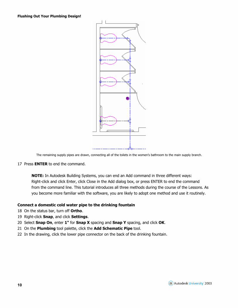
The remaining supply pipes are drawn, connecting all of the toilets in the women’s bathroom to the main supply branch.
17 Press ENTER to end the command.
NOTE: In Autodesk Building Systems, you can end an Add command in three different ways: Right-click and click Enter, click Close in the Add dialog box, or press ENTER to end the command from the command line. This tutorial introduces all three methods during the course of the Lessons. As you become more familiar with the software, you are likely to adopt one method and use it routinely.
Connect a domestic cold water pipe to the drinking fountain 18 On the status bar, turn off Ortho. 19 Right-click Snap, and click Settings. 20 Select Snap On, enter 1" for Snap X spacing and Snap Y spacing, and click OK. 21 On the Plumbing tool palette, click the Add Schematic Pipe tool. 22 In the drawing, click the lower pipe connector on the back of the drinking fountain.

Flushing Out Your Plumbing Design!
11
23 In the Add Schematic Pipes dialog box, verify that System is Domestic Cold Water.
NOTE: If System is Sanitary Black Water, you have selected the upper connector, and must click Close, and then click the Add Schematic Pipes tool before you select the lower connector.
24 In the drawing, move the cursor toward the upper right at 45 degrees, and enter 6" to add a segment of pipe at a 45-degree angle into the wall.
25 In the Add Schematic Pipes dialog box, enter 9’ for Elevation. 26 In the drawing, move the cursor down at 90 degrees, and select a point just above the column. 27 Move the cursor to the lower right at 60 degrees, and select a point just past the column. 28 Move the cursor down at 90 degrees, and select a point above the main supply line.

Flushing Out Your Plumbing Design!
12
The 60 degree fittings are added automatically.
29 In the Add Schematic Pipes dialog box, select 1" for Nominal Size.
• You can increase the size "on the fly" and the transition fitting is added automatically. 30 In the drawing, move the cursor down at 90 degrees until a Pipe Curve Connector snap displays on the main supply branch. Click the snap to connect the pipe, as shown.
The drinking fountain is connected to the main supply branch, and the transition and tee fittings are added automatically.
Notice that the fittings are placed for you even if you use the Compass and 60 degree turns. While there are several ways to route this pipe run, this solution was chosen to demonstrate the automatic insertion of 60-degree angle fittings. 31 Press ENTER to end the command. In this Lesson, you added schematic pipe to connect plumbing fixtures to the main supply branch. You used the Compass to guide the direction of your pipe runs, and two of the Building Systems snaps to help you make valid connections. The Pipe Connector snap helped you connect schematic pipe to plumbing fixtures. The Pipe Curve Connector snap helped you connect schematic pipe to existing pipe segments and runs. As you drafted your pipe runs, the proper fittings (elbows, tees, and transitions) were added. These fittings were inserted based on the schematic fitting defaults that are specified in the Domestic Cold Water system definition.
Flushing Out Your Plumbing Design!
13
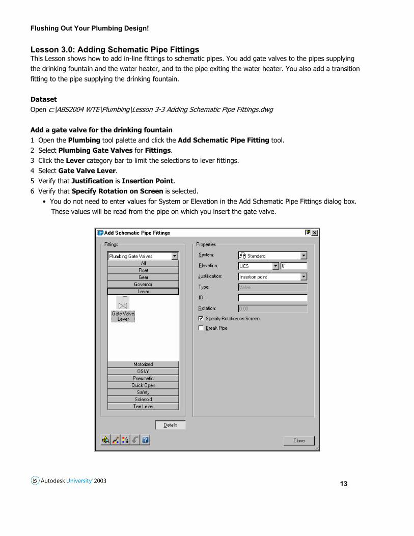
Lesson 3.0: Adding Schematic Pipe Fittings This Lesson shows how to add in-line fittings to schematic pipes. You add gate valves to the pipes supplying the drinking fountain and the water heater, and to the pipe exiting the water heater. You also add a transition fitting to the pipe supplying the drinking fountain. Dataset Open c:\ABS2004 WTE\Plumbing\Lesson 3-3 Adding Schematic Pipe Fittings.dwg Add a gate valve for the drinking fountain 1 Open the Plumbing tool palette and click the Add Schematic Pipe Fitting tool. 2 Select Plumbing Gate Valves for Fittings. 3 Click the Lever category bar to limit the selections to lever fittings. 4 Select Gate Valve Lever. 5 Verify that Justification is Insertion Point. 6 Verify that Specify Rotation on Screen is selected.
• You do not need to enter values for System or Elevation in the Add Schematic Pipe Fittings dialog box. These values will be read from the pipe on which you insert the gate valve.
Flushing Out Your Plumbing Design!
14
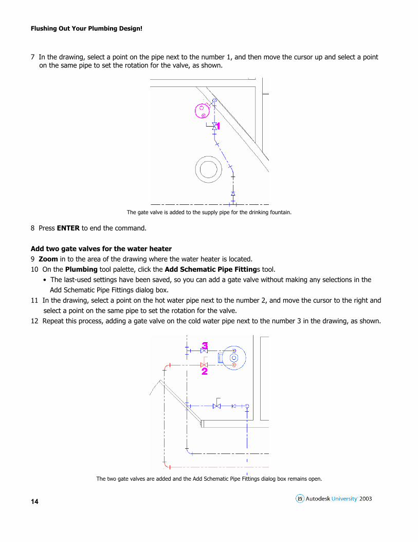
7 In the drawing, select a point on the pipe next to the number 1, and then move the cursor up and select a point on the same pipe to set the rotation for the valve, as shown.
The gate valve is added to the supply pipe for the drinking fountain.
8 Press ENTER to end the command. Add two gate valves for the water heater 9 Zoom in to the area of the drawing where the water heater is located. 10 On the Plumbing tool palette, click the Add Schematic Pipe Fittings tool.
• The last-used settings have been saved, so you can add a gate valve without making any selections in the Add Schematic Pipe Fittings dialog box. 11 In the drawing, select a point on the hot water pipe next to the number 2, and move the cursor to the right and select a point on the same pipe to set the rotation for the valve. 12 Repeat this process, adding a gate valve on the cold water pipe next to the number 3 in the drawing, as shown.
The two gate valves are added and the Add Schematic Pipe Fittings dialog box remains open.

Flushing Out Your Plumbing Design!
15
Add a transition for the drinking fountain Next, you add a transition fitting on the pipe supplying the drinking fountain. Typically, a drinking fountain needs only a 3/8" supply pipe. Inserting a reducer into the pipe will allow the pipes on either side of the reducer to be sized independently by the built-in pipe sizing tools. 13 In the Add Schematic Pipe Fittings dialog box, select Plumbing Fittings for Fittings. 14 Click the Transitions category bar to limit the selections to transition fittings. 15 Select Concentric Transition. 16 In the drawing, select a point on the cold water pipe next to the number 4, move the cursor up, and select a point on the same pipe to set the rotation for the transition, as shown.
The concentric transition is added to the supply pipe for the drinking fountain. In this Lesson, you added in-line fittings for the drinking fountain and water heater to complete your cold water supply system design. Lesson 4.0: Creating Waste Systems This Lesson shows how to add schematic pipe for the sanitary waste system. Whenever you add schematic pipe, you specify the system, such as Sanitary Black Water. The system definition controls the display properties, layers, and default fittings used in the pipe run. In this Lesson, you connect the toilets in the women’s bathroom to the main sanitary waste line, starting with the connection farthest from the sewer exit. As you add sanitary waste pipe, you specify a slope for proper drainage. When you draw sloped pipe, the software displays a glyph that shows the slope of the pipe as you draft. You can also change from one fitting to another "on the fly" as you draft. This Lesson shows how to change fittings using this method, and how to modify an existing fitting to add a cleanout. Dataset Open c:\ABS2004 WTE\Plumbing\Lesson 3-4 Creating Waste Systems.dwg Connect a sanitary waste pipe to a toilet 1 On the status bar, turn off Snap and Osnap, and verify that Polar and Otrack are turned off. 2 Open the Plumbing tool palette and click the Add Schematic Pipe tool. 3 In the Add Schematic Pipes dialog box, specify the settings:
• Select Black Pipe for Style. You do not need to specify values for System, Elevation, or Size, as the correct values will be read from the waste connector on the toilet when you select it.

Flushing Out Your Plumbing Design!
16
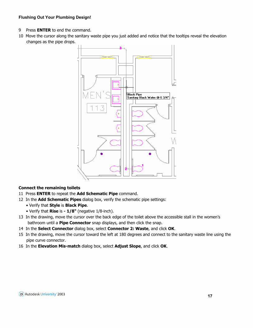
• Enter - 1/8" (negative 1/8-inch) for Rise, and press ENTER. The value you enter for Rise works in conjunction with the Run value to determine the slope of the pipe. In this case, the pipe drops 1/8" for every foot it travels, yielding a slope of - 0.7%.
4 In the drawing, move the cursor over the back edge of the toilet numbered 1 until a Pipe Connector snap displays, and click the snap.
5 In the Select Connector dialog box, select Connector 2: Waste, and click OK. 6 Move the cursor to the left at 180 degrees, and select a point near the number 2. 7 Move the cursor toward the top of the drawing at 90 degrees and select a point near the number 3. As you work in the drawing, notice the glyph showing the direction of the drop. 8 Move the cursor toward the left at 180 degrees, and enter 137’ to extend the pipe to the building’s sewer exit, as shown.
The fixture farthest from the sewer exit is connected to the sanitary waste system.
Flushing Out Your Plumbing Design!
17
9 Press ENTER to end the command. 10 Move the cursor along the sanitary waste pipe you just added and notice that the tooltips reveal the elevation changes as the pipe drops.
Connect the remaining toilets 11 Press ENTER to repeat the Add Schematic Pipe command. 12 In the Add Schematic Pipes dialog box, verify the schematic pipe settings:
• Verify that Style is Black Pipe. • Verify that Rise is - 1/8" (negative 1/8-inch).
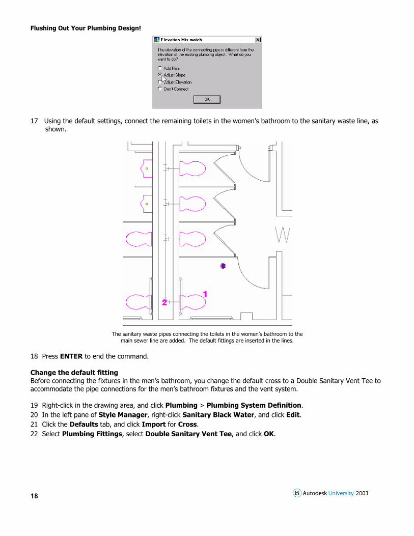
13 In the drawing, move the cursor over the back edge of the toilet above the accessible stall in the women’s bathroom until a Pipe Connector snap displays, and then click the snap. 14 In the Select Connector dialog box, select Connector 2: Waste, and click OK. 15 In the drawing, move the cursor toward the left at 180 degrees and connect to the sanitary waste line using the pipe curve connector. 16 In the Elevation Mis-match dialog box, select Adjust Slope, and click OK.
Flushing Out Your Plumbing Design!
18
17 Using the default settings, connect the remaining toilets in the women’s bathroom to the sanitary waste line, as shown.
The sanitary waste pipes connecting the toilets in the women’s bathroom to the
main sewer line are added. The default fittings are inserted in the lines. 18 Press ENTER to end the command. Change the default fitting Before connecting the fixtures in the men’s bathroom, you change the default cross to a Double Sanitary Vent Tee to accommodate the pipe connections for the men’s bathroom fixtures and the vent system. 19 Right-click in the drawing area, and click Plumbing > Plumbing System Definition. 20 In the left pane of Style Manager, right-click Sanitary Black Water, and click Edit. 21 Click the Defaults tab, and click Import for Cross. 22 Select Plumbing Fittings, select Double Sanitary Vent Tee, and click OK.

Flushing Out Your Plumbing Design!
19
23 Click OK twice to close Style Manager. 24 On the Plumbing tool palette, click the Add Schematic Pipe tool. 25 In the Add Schematic Pipes dialog box, click the arrow to the right of Preferences, click Cross, and verify that Double Sanitary Vent Tee is the default.
26 In the men’s bathroom, move the cursor over the back edge of the toilet that is located between the accessible stall and the first urinal. When a Pipe Connector snap displays, click the snap. 27 In the Select Connector dialog box, select Connector 2: Waste, and click OK. 28 In the drawing, move the cursor toward the right at 0 degrees, and connect to the Pipe Connector snap on the
Flushing Out Your Plumbing Design!
20
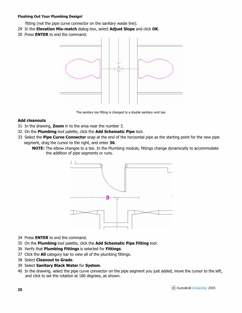
fitting (not the pipe curve connector on the sanitary waste line). 29 In the Elevation Mis-match dialog box, select Adjust Slope and click OK. 30 Press ENTER to end the command.
The sanitary tee fitting is changed to a double sanitary vent tee. Add cleanouts 31 In the drawing, Zoom in to the area near the number 3. 32 On the Plumbing tool palette, click the Add Schematic Pipe tool. 33 Select the Pipe Curve Connector snap at the end of the horizontal pipe as the starting point for the new pipe segment, drag the cursor to the right, and enter 36.
NOTE: The elbow changes to a tee. In the Plumbing module, fittings change dynamically to accommodate the addition of pipe segments or runs.
34 Press ENTER to end the command. 35 On the Plumbing tool palette, click the Add Schematic Pipe Fitting tool. 36 Verify that Plumbing Fittings is selected for Fittings. 37 Click the All category bar to view all of the plumbing fittings. 38 Select Cleanout to Grade. 39 Select Sanitary Black Water for System. 40 In the drawing, select the pipe curve connector on the pipe segment you just added, move the cursor to the left, and click to set the rotation at 180 degrees, as shown.
Flushing Out Your Plumbing Design!
21
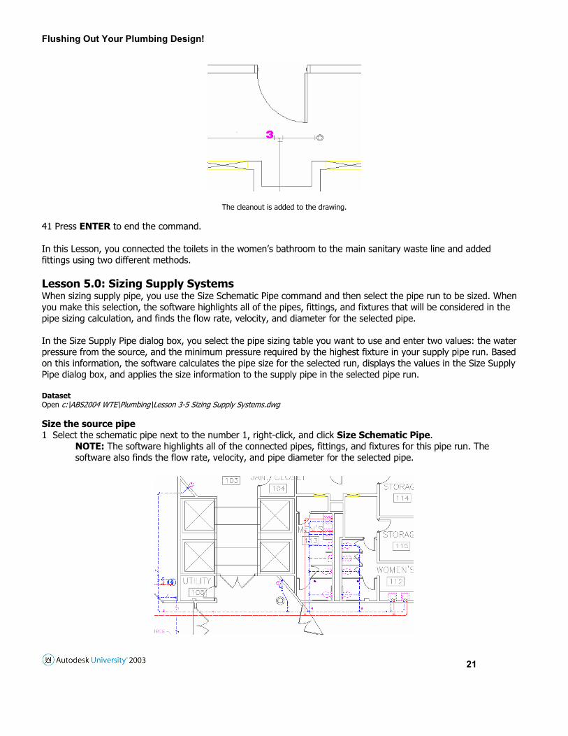
The cleanout is added to the drawing.
41 Press ENTER to end the command. In this Lesson, you connected the toilets in the women’s bathroom to the main sanitary waste line and added fittings using two different methods. Lesson 5.0: Sizing Supply Systems When sizing supply pipe, you use the Size Schematic Pipe command and then select the pipe run to be sized. When you make this selection, the software highlights all of the pipes, fittings, and fixtures that will be considered in the pipe sizing calculation, and finds the flow rate, velocity, and diameter for the selected pipe. In the Size Supply Pipe dialog box, you select the pipe sizing table you want to use and enter two values: the water pressure from the source, and the minimum pressure required by the highest fixture in your supply pipe run. Based on this information, the software calculates the pipe size for the selected run, displays the values in the Size Supply Pipe dialog box, and applies the size information to the supply pipe in the selected pipe run. Dataset Open c:\ABS2004 WTE\Plumbing\Lesson 3-5 Sizing Supply Systems.dwg Size the source pipe 1 Select the schematic pipe next to the number 1, right-click, and click Size Schematic Pipe.
NOTE: The software highlights all of the connected pipes, fittings, and fixtures for this pipe run. The software also finds the flow rate, velocity, and pipe diameter for the selected pipe.

Flushing Out Your Plumbing Design!
22
2 In the Size Supply Pipe dialog box, specify the design values: • Select Tutorial Standard for Pipe Sizing Table. When calculating the Developed Length of the pipe run, the software refers to the specified supply pipe sizing table to get equivalent pipe length values for all connected fittings and valves. • Verify that Pressure at Source is 60. • Verify that Pressure-Highest Fixture is 15. • The results of the supply pipe sizing are displayed under Calculations for the Longest Run Calculations at Selected Component.
3 Review the pipe sizing results in Calculations for the Longest Run.
NOTE: This section displays the developed length, elevation difference, pressure drop, and downstream Fixture units for the longest connected pipe run within your selection. These values are not editable. To calculate Developed Length, the software adds the lengths of the pipe segments to the equivalent pipe lengths of all connected fittings and valves located on the same run. To calculate Downstream
Fixture Units, the software reads and totals the required cold water supply fixture units for all Connected fixtures.
4 Review the pipe sizing results in Calculations at Selected Component. NOTE: This section displays the flow rate, velocity, and pipe diameter for the pipe you selected. These values
are not editable. To find these values, the software reads the flow direction for the pipe, and then reads the values for the end of the pipe that is closest to the source.

Flushing Out Your Plumbing Design!
23
5 Notice that the selected pipe run is sized at 2".
NOTE: Based on the information in your drawing, the values in the Tutorial Standard supply pipe sizing table, and the information you entered for Pressure at Source and Pressure-Highest Fixture, the selected pipe is sized at 2".
6 Click OK to close the Size Supply Pipe dialog box. 7 Verify that the calculated size has been added to the property information for the schematic pipe:
• Select the pipe you just sized. • Right-click, and click Schematic Pipe Modify. • Notice that Nominal Size is 2".
• Click OK to close the Modify Schematic Pipes dialog box.
Size the main branch 8 In the drawing, select the cold water supply pipe next to the number 2, right-click, click Size Schematic Pipe.
NOTE: The software highlights all of the connected pipes, fittings, and fixtures for sizing this pipe run. The software also finds the flow rate, velocity, and pipe diameter for the selected pipe.

Flushing Out Your Plumbing Design!
24
9 In the Size Supply Pipe dialog box, specify the design values:
• Verify that Tutorial Standard is selected for Pipe Sizing Table. • Verify that Pressure at Source is 60. • Verify that Pressure-Highest Fixture is 15. • Review the pipe sizing results. NOTE: The values in the Calculations for the Longest Run and Calculations at Selected Component sections are
the result of the pipe sizing and are not editable. Based on the information in your drawing, the values in the Tutorial Standard supply pipe sizing table, and the information you entered for Pressure at Source and Pressure-Highest Fixture, the selected pipe is sized at 2".
10 Click OK to close the Size Supply Pipe dialog box.
Flushing Out Your Plumbing Design!
25
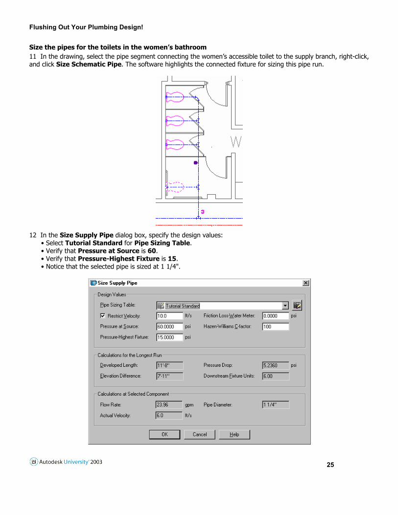
Size the pipes for the toilets in the women’s bathroom 11 In the drawing, select the pipe segment connecting the women’s accessible toilet to the supply branch, right-click, and click Size Schematic Pipe. The software highlights the connected fixture for sizing this pipe run.
12 In the Size Supply Pipe dialog box, specify the design values:
• Select Tutorial Standard for Pipe Sizing Table. • Verify that Pressure at Source is 60. • Verify that Pressure-Highest Fixture is 15. • Notice that the selected pipe is sized at 1 1/4".
Flushing Out Your Plumbing Design!
26
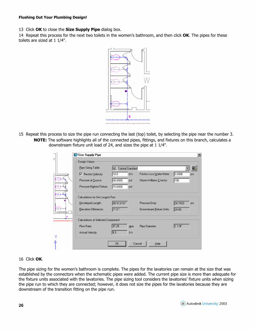
13 Click OK to close the Size Supply Pipe dialog box. 14 Repeat this process for the next two toilets in the women’s bathroom, and then click OK. The pipes for these toilets are sized at 1 1/4".
15 Repeat this process to size the pipe run connecting the last (top) toilet, by selecting the pipe near the number 3.
NOTE: The software highlights all of the connected pipes, fittings, and fixtures on this branch, calculates a downstream fixture unit load of 24, and sizes the pipe at 1 1/4".
16 Click OK. The pipe sizing for the women’s bathroom is complete. The pipes for the lavatories can remain at the size that was established by the connectors when the schematic pipes were added. The current pipe size is more than adequate for the fixture units associated with the lavatories. The pipe sizing tool considers the lavatories’ fixture units when sizing the pipe run to which they are connected; however, it does not size the pipes for the lavatories because they are downstream of the transition fitting on the pipe run.

Flushing Out Your Plumbing Design!
27
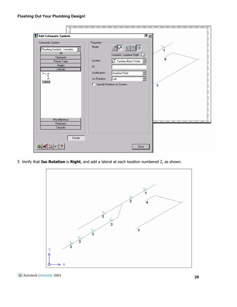
Lesson 6.0: Creating Isometric Diagrams This Lesson shows how to add schematic symbols to schematic lines in your diagram. The schematic symbols you add are in-line symbols because they are added to existing schematic lines. In-line symbols are anchored to schematic lines. If you move a line connected to an in-line symbol, the symbol moves with the line. Schematic symbols are 2D objects. Like schematic lines, you can place schematic symbols in either Isometric or Orthographic mode. When you place a schematic symbol on a schematic line using the schematic curve connector, the symbol reads the line’s mode (Isometric or Orthographic) and orients itself to the angle of the line. Dataset Open c:\ABS2004 WTE\Plumbing\Lesson 3-6 Creating Isometric Diagrams.dwg Add a lateral to the waste line 1 Open the MEP tool palette and click the Add Schematic Symbols tool. 2 Select Plumbing Symbols - Isometric for Schematic Symbol, and click the Laterals category bar.
3 Select Lateral, and specify the settings:
• Verify that Mode is Ortho. • Select Sanitary Black Water for System. • Verify that ID is clear. • Verify that Justification is Insertion Point. • Clear Specify Rotation on Screen. • Enter 180 for Rotation.

Flushing Out Your Plumbing Design!
28
4 In the drawing, select the schematic line at the number 1, and note that the Add Schematic Symbols dialog box shows that Mode has changed to Isometric.
NOTE: When you anchored the schematic symbol to the line using the schematic curve connector, the symbol inherited the mode of the line (Isometric), and the Mode setting was updated to reflect the change. The symbol was placed in Isometric mode and read Isoplane Right from the line. When you place schematic symbols in Isometric mode, you have rotation options. The rotation options are not defined by degrees; they use Up, Down, Right, and Left. The option called Top uses a different set of rotations than the other options.
Flushing Out Your Plumbing Design!
29
5 Verify that Iso Rotation is Right, and add a lateral at each location numbered 2, as shown.

Flushing Out Your Plumbing Design!
30
The laterals are anchored to the schematic lines to which they were added, and the Add Schematic Symbols dialog box remains open.
The anchored relationship is maintained when the laterals are copied or moved.
Add a mop sink trap 6 In the Add Schematic Symbols dialog box, click the Fixture Traps category bar, and select Fixture Stack. 7 Verify that Iso Rotation is Left. 8 In the drawing, place the symbol at the end of the schematic line numbered 3, as shown.
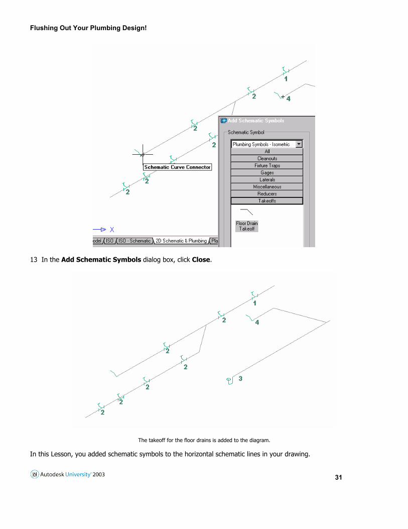
The mop sink trap is added to the diagram, and the Add Schematic Symbols dialog box remains open. Add a takeoff for the floor drains 9 In the Add Schematic Symbols dialog box, click the Takeoffs category bar, and select Floor Drain Takeoff. 10 Select Up for Iso Rotation. 11 In the drawing, place the symbol at the endpoint of the line numbered 4. 12 Repeat, adding the same symbol with an Up rotation at the endpoint of the other horizontal schematic line, as shown.
Flushing Out Your Plumbing Design!
31
13 In the Add Schematic Symbols dialog box, click Close.
The takeoff for the floor drains is added to the diagram. In this Lesson, you added schematic symbols to the horizontal schematic lines in your drawing.