Embed Size (px)
Citation preview

WL-TR-95 -3038
FLUTTER CONTROL OF AN ADAPTIVE LAMINATED COMPOSITE PANEL WITH PIEZOELECTRIC LAYERS
AFZALSULEMAN VIPPERLA B. VENKAYYA
Design Methods Development Section Design Development Branch Structures Division
August 1994
FINAL REPORT FOR PERIOD SEPTEMBER 1992 - AUGUST 1994
8S&. ITO*
sagas****
Approved for public release; distribution is unlimited.
FLIGHT DYNAMICS DIRECTORATE WRIGHT LABORATORY AIR FORCE MATERIEL COMMAND WRIGHT PATTERSON AFB OH 45433-7542
19950522 021
DTIG QÜÄLH'£ m&'üiCJffi0 1

NOTICE
When Government drawings, specifications, or other data are used for any purpose other than in connection with a definitely related Government procurement operation, the United States Government thereby incurs no responsibility or any obligation whatsoever. The fact that the Government may have formulated or in any way supplied the said drawings, specifications, or other data, is not to be regarded by implication, or otherwise as in any manner, as licensing the holder or any other person or corporation; or as conveying any rights or permission to manufacture, use, or sell any patented invention that may in any way be related thereto.
This report is releasable to the National Technical Information Service (NTIS). At NTIS, it will be available to the general public, including foreign nations.
This technical report has been reviewed and is approved for publication.
VIPPERLA B. VENKAYYA, Principal Scientist NELSON D. WOLT, Techma Design Methods Development Section Design Methods Development Design Development Branch Design Development Branch
'J
/GEORQ^RTB0LDERBY, C Designxtevelopment Branch Structures Division
"If your address has changed, if you wish to be removed from our mailing list, or if the addressee is no longer employed by your organization please notify WL/FIBAD, Wright- Patterson AFB OH 45433-7542 to help us maintain a current mailing list".
Copies of this report should not be returned unless return is required by security considerations, contractual obligations, or notice on a specific document.

DISCLAIM» NOTICE
THIS DOCUMENT IS BEST
QUALITY AVAILABLE. THE COPY
FURNISHED TO DTIC CONTAINED
A SIGNIFICANT NUMBER OF
COLOR PAGES WHICH DO NOT
REPRODUCE LEGIBLY ON BLACK
AND WHITE MICROFICHE.

REPORT DOCUMENTATION PAGE Form Approved OMB No. 0704-0188
Public reporting burden for this collection of information is estimated to average 1 hour per response, including the time for reviewing instructions, searching existing data sources, gathering and maintaining the data needed, and completing and reviewing the collection of information. Send comments regarding this burden estimate or any other aspect of this collection of information, including suggestions for reducing this buroen. to Washington Headauarters Services, Directorate tor information Operations and Reports, 1215 Jefferson Davis Highway, Suite 1204, Arlington. VA 22202-4302, and to the Office of Management and Budget, Paperwork Reduction Project (0704-0188), Washington, DC 20503.
1. AGENCY USE ONLY (Leave blank) 2. REPORT DATE
August 1994 3. REPORT TYPE AND DATES COVERED
Final Report, 1 September 1992-31 August 4. TITLE AND SUBTITLE
Flutter Control of an Adaptive Laminated Composite Panel with Piezo- electric Layers
5. FUNDING NUMBERS
NRC/AFOSR PE: 61102
6. AUTHOR(S)
Afzal Suleman and Vipperla B. Venkayya
7. PERFORMING ORGANIZATION NAME(S) AND ADDRESS(ES) NRC/AFOSR Research Associateship Programs 2101 Constitution Ave. Washington DC
PERFORMING ORGANIZATION REPORT NUMBER
9. SPONSORING/MONITORING AGENCY NAME(S) AND ADDRESS(ES) Flight Dynamics Directorate Wright Laboratory Air Force Materiel Command Wright Patterson AFB OH 45433-7542
10. SPONSORING /MONITORING AGENCY REPORT NUMBER
WL-TR-95-3038
11. SUPPLEMENTARY NOTES
12a. DISTRIBUTION/AVAILABILITY STATEMENT
Approved for public release; Distribution unlimited. 12b. DISTRIBUTION CODE
13. ABSTRACT (Maximum 200 words)
A new finite element formulation of an adaptive composite laminated panel with piezoelectric sen- sors and actuators is presented. Classical laminated theory with electromechanical induced actuation and variational principles are used to formulate the equations of motion. The finite element model based on the bilinear Mindlin plate theory with 24 structural degrees of freedom and one electrical degree of free- dom per piezoelectric layer is much simpler and computationally more efficient than models based on solid element formulations with a significant decrease in the number of degrees of freedom. The numer- ical results from simulations agree well with data reported in the literature.
Next, the effectiveness of using the adaptive composite panel to control panel flutter is examined. First order piston theory is used to model the supersonic flow. The piezoelectric actuators are used pas- sively to induce inplane forces to alter the panel stiffness characteristics. The results show that piezo- electric devices can significantly increase panel flutter velocities. However, it was found that the added mass to stiffness ratio and the piezoelectric patch configuration are two factors affecting actuator performance.
'.'.. SUE'FCT TF.r'.r/S Finite Element Analysis, Piezoelectric Actuation and Sensing, Panel Flutter, Passive Control
15. NUMBER OF PAGES 76
16. PRICE CODE
SECURITY CLASSIFICATION' OF REPORT
Unclassified
18. SECURITY CLASSIFICATION OF THIS PAGE
Unclassified
19. SECURITY CLASSIFICATION OF ABSTRACT
Unclassified
20. LIMITATION OF ABSTRACT
Unlimited NSI\! 7540-01-280-5500 Standard Form 298 (Rev. 2-89)
"'escribed by ANS; StC Z39-18

ABSTRACT v FOREWORD vi LIST OF FIGURES vii LIST OF TABLES ix
1. INTRODUCTION 1
1.1 ENABLING TECHNOLOGIES 2
1.1.1 Materials 3
1.1.2 Actuators 5
1.1.3 Sensors 7
1.1.4 Control Design and Optimization 8
1.2 APPLICATIONS 10
1.3 PRESENT INVESTIGATION 13
2. ELECTROMECHANICAL FINITE ELEMENT 15
2.1 FINITE ELEMENT FORMULATION 16
2.1.1 Mindlin Plate Theory 16
2.1.2 Electromechanical Plate Finite Element 18
2.1.3 Constitutive Relations 20
2.1.4 Strain-Displacement Relations 21
2.1.5 Stress-Strain Relations 22
2.2 EQUATIONS OF MOTION 24
2.3 SIMULATION RESULTS 24
2.3.1 Static Actuation and Sensing 25
2.3.2 Eigenvalue Solution 27
2.4 COMMERCIAL FEM CODES 36
2.4.1 ANSYS - Swanson Analysis Systems, Inc 36
2.4.2 ABAQUS - Hibbit, Karlsson & Sorensen, Inc 36
2.4.3 NASTRAN(CSA) - CSAR Corporation 37
2.4.4 NASTRAN(MSC) - The MacNeal-Schwendler Corp. . . 39
2.4.5 Simulation Results 39
in
2.5 THERMAL ANALOGY 40
2.6 PRELIMINARY REMARKS 41
3. APPLICATION - FLUTTER CONTROL 43
3.1 DESIGN PROBLEM 43
3.2 PANEL FLUTTER MODEL 46 3.2.1 First Order Piston Theory 46 3.2.2 The Effect of Initial Pre-Stresses 48 3.2.3 Equations of Motion 49
3.3 PASSIVE CONTROL 50
3.4 PRELIMINARY REMARKS 54
4. CONCLUDING REMARKS 56
REFERENCES 58
APPENDICES A PROGRAM INPUT DATA 62 B POST-PROCESSING PROGRAM 67
IV
FOREWORD
This technical report was prepared by Dr. Afzal Suleman and Dr. Vipperla B. Venkayya, Design Development Branch, Structures Division of the Flight Dynamics Directorate. This effort was supported by the National Research Council (NRC) and the Air Force Office for Scientific Research (AFOSR). This technical report covers the work accomplished between September 1992 and August 1994.
Accession tov
ms GRA&I DTIC KÄB Unannounced Justification.
D n
By—.
VI

LIST OF FIGURES
Figure 1.1 Key technologies and fields that need to be addressed in order to
enable adaptation in structural systems.
Figure 1.2 Application of adaptive structures technology to aeronautical systems.
Figure 2.1 Finite element composite plate element showing the displacement de-
grees of freedom for the mechanical elastic properties and the electrical
degrees of freedom for the piezoelectric behaviour.
Figure 2.2 Piezoelectric patch showing direction of polarization and electrode
layout.
Figure 2.3 (a) Test study comparison between the present formulation and Tzou
and Tseng (1990) showing the experimental apparatus for the piezo-
electric bimorph plate; (b) the finite element model with 53 degrees
of freedom; (c) the static actuation mechanism; (d) the static sensing
mechanism.
Figure 2.4 (a) The experimental apparatus showing the Gr/Epoxy [0/±45] can-
tilevered plate studied by Crawley and Lazarus (1991); (b) The finite
element model with 880 degrees of freedom; (c) the static actuation
mechanism; (d) the deformed configuration of the cantilevered plate
resulting from the static actuation for an applied voltage of ±158V;
(e) comparison of the sensing voltages along the central tier of piezo-
electric elements due to voltage of ±1007 applied on the outer tiers of
piezoelectrics; and (e) the deformed configuration showing the sensed
voltages along the central tier of piezoelectrics.
Figure 2.5 Comparison between the present formulation and Ha, Keilers and
Vll

Chang (1992) showing: (a) the relationship between the required ac-
tuation voltages and the various tip loading conditions; (b) The de-
- formed configuration of the cantilevered plate under the action of the
mechanical tip load and electric actuation.
Figure 2.6 Eigenvalue solution comparison between the present formulation and
Hollkamp (1994) showing: (a) the experimental apparatus for the
aluminum cantilever beam with 6 pairs of PZT tiles; and (b) the
finite element model with 195 degrees of freedom.
Figure 2-7 Comparison between the solid element models developed in ANSYS
and ABAQUS and the composite plate element developed here.
Figure 2-8 An example to establish the analogy between the thermal and piezo-
electric behaviour.
Figure 3.1 Self excited oscillations of an external panel of a flight vehicle exposed
to supersonic air flow (M > y/2)
Figure 3.2 Effect of in-plane tensile forces.
Figure 3.3 Initial in-plane pre-stresses on the panel due to piezoelectric actuation.
Figure 3.4 The natural frequencies solution as a function of dynamic pressure.
The fundamental mode shapes are shown in vacuum and following
the onset of flutter.
Figure 3.5 Critical dynamic pressure results for a central piezoelectric patch con-
figuration for two sizes of actuation capabilities.
Figure 3.6 Critical dynamic pressure results for three different patch configura-
- tions.
L
viii

LIST OF TABLES
Table 2-1 Input data card deck for ANSYS showing the necessary commands to
perform a piezoelectric analysis.
Table 2-2 Input data card deck for ABAQUS showing the necessary commands
to perform a piezoelectric analysis.
Table 3-1 Material properties and operating conditions for a Gl 195 PZT piezo-
ceramic.
Table 3-2 The actuation capabilities and power requirements for a typical piezo-
ceramic patch.
Table 3-3 Passive control methodology flowchart.
IX

CHAPTER
ONE
INTRODUCTION
In the past decade, technological developments in materials and computer sci-
ences have evolved to the point where their synergistic combination have culminated
in a new field of multi-disciplinary research in adaptation. The advances in material
sciences have provided a comprehensive and theoretical framework for implementing
multifunctionality into materials, and the development of high speed digital com-
puters has permitted the transformation of that framework into methodologies for
practical design and production. The concept is elementary: a highly integrated sen-
sor system provides data on the structures environment to a processing and control
system which in turn signals integrated actuators to modify the structural properties
in an appropriate fashion.
U.S.A., Japan and Europe have been interested for some time in applying the
adaptation concept to high performance aircraft, high pointing accuracy space sys-
tems and variable geometry manipulators.
In the USA, studies at MIT (Lazarus, Crawley and Bohlman, 1990) have investi-
gated the properties of composite laminates with embedded piezoelectric actuators.
Work performed at VPI (Anders and Rogers, 1990) has proposed fiber optic sensors
embedded in composite materials for sensing and shape memory alloys for actua-
tion of structures. Adaptive structure concepts for vibration suppression are being
developed at JPL as well (Wada, 1991). Activities here focus on the development
of concepts, integrated design methodology and ground test methodology including

the development of passive and active structural members. Since then numerous
other investigators have proposed the application of adaptive technologies to struc-
tural systems, and various workshops, conferences (e.g. International Conference on
Adaptive Structures) and journals (e.g. Journal of Intelligent Materials, Systems and
Structures) have been organized to provide a forum for discussion on these matters.
Most of the work undertaken in Japan (Miura and Natori, 1991) has concentrated
on adaptive truss structures. In the early eighties, researchers at ISAS proposed
a coilable longeron mast concept to efficiently package space truss structures with
capabilities to adapt its geometry to mission requirements. Subsequently, extensive
research has been carried out in the areas of vibration suppression and shape control,
with particular application to space structures.
European activities include the work on shape memory alloys at the University
of Twente in the Netherlands and piezoceramics at ONERA in France. Potential
space applications for adaptive structures are also being explored at ESA (Breitbach,
1991). Recently, the Smart Structures Research Institute at Strathclyde University
in Scotland has also been established (Gardiner et al., 1991)
1.1 ENABLING TECHNOLOGIES
There are two key technological developments which have combined to establish
the potential feasibility of adaptive structures. The first is the development of func-
tional materials (materials science) and their utilization in devices such as distributed
actuators and sensors (mechanical engineering). The second development comes in
the electrical engineering field, with new control algorithms and signal processing
technologies. Figure 1 depicts technologies and other research fields which need to be
addressed to enable the implementation of adaptive materials into structural systems.

FEED-BACK SYSTEM
• SENSORS • ACTUATORS
CONTROLS
• SIGNAL PROCESSING
• CONTROLLERS
ENVIRONMENT DISTURBANCE
DETERMINISTIC STOCHASTIC
STRUCTURES • STATICS • DYNAMICS • GLOBAL MODELS • LOCAL fSSUES
SENSITIVITY • ANALYTICAL • FINITE DIFFERENCE • EXPERIMENTAL
MATERIALS
• CONSTITUTIVE MODELS MULTI-FUNCTIONAL MATERIALS
IDENTIFICATION
• TIME DOMAIN • TRANSFER
FUNCTION • ESTIMATION
OPTIMIZATION NON-LINEAR PROGRAMMING LINEAR PROGRAMMING
Figure 1.1 Key technologies and fields that need to be addressed in order to
enable adaptation in structural systems.
1.1.1 Materials
Materials science has shown a distinct trend in the development of materials
with functional properties. There are five types of adaptive materials that have been
widely reported in the literature: piezoelectrics, shape memory alloys, electrostrictors,
magnetostrictors and electro-rheological fluids.

Piezoelectric materials currently come in the form of piezoceramics and piezopoly-
mers. Piezoceramics are polycrystalline ceramics. These materials are hard and dense
and can be manufactured in many shapes and tailored to various applications. The
most common type is made of Lead-Zirconate-Titanate (PZT). The piezoelectric ef-
fect occurs when a pressure is applied to a material creating an electric charge on the
surface of the material and conversely, a change in the dimensions of the material is
observed with an applied electric field. Piezopolymers (e.g. Polyvinylidene fluoride,
PVDF) are clear plastic films which can also be readily cut and shaped in complex
patterns.
Shape memory alloys have the ability to recover a particular shape when activated
by an external stimulus. One common type is Nitinol, which is a nickel and titanium
alloy that undergoes a reversible phase transformation from austenite to martensite.
The shape of the alloy which is to be remembered is formed at the high temper-
ature austenite phase. The alloy can be reshaped below the phase transformation
temperature in the martensitic phase. Once the alloy is heated above the transfor-
mation temperature, the originally formed shape is remembered, exerting stresses up
to 100,000 psi if restrained, or creating strains up to 8% if unrestrained.
Like piezoelectrics, electrostrictive ceramics also change in dimension when an
electric field is applied. However, the strain induced is proportional to the square of
the electric field, so positive displacements are always realized, i.e. the material can-
not contract. Magnetostrictive alloys (e.g. Terfenol-D), expand under the influence
of a magnetic field. Electrorheological fluids consist of polarizable, high dielectric
constant particles suspended in a dielectric fluid. When exposed to an electric field,
the viscosity in these fluids increases.
1.1.2 Actuators
Sensors and actuators are analogous to the nerve and muscle systems, respectively,
of a human body that is itself an adaptive system. The signals that are sensed by
the sensors and modified by the actuators must be processed in real time under very
restrictive conditions. A number of actuator types are available:
Piezoelectric actuators in general, are best suited for high frequency and medium
stroke with low to medium power requirements. Piezoelectric crystals tend to be
difficult to manufacture and use because of their brittleness. Piezoelectric fibers are
an attractive option due to the ease in incorporating them into the manufacturing
process, however, they are difficult to produce in long enough lengths to be useful.
Piezoelectric ceramics and polymers are both good candidates for adaptive structures.
They can be machined to a wide variety of shapes, and have good strength, stiffness,
stroke and bandwidth characteristics. However, the application of piezoceramic ma-
terials in actuator devices is limited by the material non-linearities and high density.
Although the low modulus in piezopolymers often precludes their use as actuators,
their high field tolerance and electro-mechanical coupling result in large actuation
strains which make them effective actuators in applications where obtaining a good
mechanical impedance match is possible.
Electrostrictive devices appear to be especially suited for high frequency and low
stroke applications, with lower power requirements. The advantages of constrictive
ceramics over piezoelectrics is that they can potentially achieve a larger displacement,
hysteresis appears less significant, and since they have a higher density charge, they
can produce a greater force when activated.
Furthermore, electrostrictives do not exhibit hysteresis and creep at low frequen-

cies and moderate temperatures, due to the absence of permanent polarization. This
gives these materials excellent set point accuracy, which makes these actuators ideal
choices for low frequency precision positioning.
Magnetostrictive materials are the magnetic analogy of electrostrictives. Ferro-
magnetic materials, or magnetostrictors, strain as a result of the interaction between
applied magnetic fields and magnetic dipoles in the material. Magnetostrictive ma-
terials have a relatively high modulus, they exhibit fast responses and produce large
actuation strains. However, the bandwidth of these materials is limited by mechanical
resonances, magnetic eddy currents and high energy requirements.
Shape Memory Alloys are ideal actuators for low frequency and high stroke ap-
plications, with lower power requirements. Actuator applications are generally in the
form of fine wires, which are activated by resistive heating when an electric current is
passed through the wire. This heating raises the metal to its austenite temperature
inducing it to return to its original shape. The high force and large stroke capability
exhibited by these materials make them excellent actuator materials. Fatigue may
become a problem, especially if the alloy is deformed to a high strain configuration.
Nickel-Titanium alloys (Nitinol) exhibit unique mechanical memory characteristics
which make them suitable candidates.
Electro-Rheological (ER) fluids have the property that their viscosity changes
drastically upon application of a voltage. This effect has been used to demonstrate
an increased damping rate when the ER fluid is activated. ER fluids respond quickly
enough to warrant their application in active control, however, they present weight
penalties associated with introducing fluid into the structure, and there is uncertainty
about whether they can be made to be stable for a long enough period of time. The

most common ER fluids are composed of silicon oil and corn starch.
Mechanical actuators are not considered suitable in adaptive structures appli-
cations because they tend to be bulky in size, and embedding the devices in an
automated manufacturing process would be difficult.
1.1.3 Sensors
Piezoelectrics sensors use the same type of materials described for use as actu-
ators. The operation of these transducers is essentially a reversible process. They
can act as sensors by producing a voltage change in response to deformation. In par-
ticular, piezopolymers make excelent sensors due to their low modulus and weight,
and they can easily be shaped into many geometries which allows for flexible and
unobtrusive use in many sensing applications.
Strain Gages are simple and inexpensive sensors, and represent a mature tech-
nology. However, since they are discrete devices, they may be difficult to embed in
a composite type structure. This problem can be overcome by producing a thin film
with gages printed on it at regular intervals, and subsequently bonding it to the wall
of a structure during the manufacturing process.
Fiber Optics make excellent sensors because they are immune to the electromag-
netic interference which eliminates costly and heavy shielding that is necessary to
support electrical sensors. Additionally, they can be made extremely small and can
be embedded into composite materials without structural degradation. The inherent
high bandwidth of fiber optic sensors and the data links supporting them enables
the potential of systems with a large number of sensors. Finally, because of the high
melting point of these fibers and the high inherent strength of glass, they are able

to perform in extremely hostile environments at high temperatures, vibrations and
shock loadings.
1.1.4 Control Design and Optimization
There are two levels of control methodology which need to be considered in adap-
tive structures: local control and global control. In the design of local control, the
controller design needs to take into account the large number of actuators and sensors
distributed throughout the structure. It may be feasible to use local connections to
introduce some level of control or damping into the structure before attempting to
close global feedback loops. However, the localized control lacks good performance
(Lazarus and Napolitano, 1993). Global control design consists of a centralized con-
troller in which the signals from all the sensors are fed to a centralized processor.
The control inputs are then computed and fed back to the distributed actuators. The
centralized design has better performance than local control, but is computationally
inefficient. A single centralized processor would have to process signals at rates cor-
responding to the highest mode being controlled, and would have to read all of the
inputs and calculate all of the outputs for the entire system. This would impose large
computational requirements (typically in the order of [100x100] to [1,000x1,000] com-
putations at speeds of 1,000 Hz) which cannot be achieved even with dedicated real
time control computers (capable of computations in the order of [10x10] to [30x30]
computations at 1,000 Hz). As a secondary consideration, the centralized scheme
requires the transmission of many relatively low level electrical signals, all the way
from the sensor to the centralized processing area, thus producing low signal-to-noise
ratios.
One approach proposed to address the problems encountered in exclusively local
and exclusively gobal control schemes is to use a combination of both, and this is

often referred to as hierarchic or multi-level control architecture (Hall et. al. 1991).
In this scheme, there would be two levels of control, a centralized controller for overall
performance and distributed processing for local control. Such a structure would be
divided into finite control elements with local processors providing local control using
measurements made within the element and actuators within the element. An average
representation of the shape within each element would then be passed on to the global
processor for providing global control. This division of the control function into local
and global control has been found to be quite practical, and from an engineering
perspective completely reproduces the performance of a truly centralized controller.
Applications of control algorithms such as Linear Quadratic Gaussian/Loop Trans-
fer Recovery (LQG/LTR) and H^ algorithms seem to be promising since the struc-
tures have normally uncertain and multivariable models. The Hoc design is attractive
because it can cope with a system having many inputs and outputs, and it can guar-
antee a degree of robustness. Moreover, it is an optimization-based technique which
involves the designer in selecting the tuning parameters whilst the complex mathe-
matical algorithms are executed on the computer.
For signal processing in structural control, the interface with sensors and actuators
has to be addressed first so that the input and output of a signal processing system
can be identified. This interface relates to the sensor type, the number of sensors
required and the manner in which they are deployed. From these questions, the
type and volume of signals to be processed, the dynamic range of input signals, and
the accuracy and speed requirements for processing can be determined. A similar
analysis for actuators will provide guidelines for output signal processing. Research
in signal processing needs to identify existing signal processing techniques suitable
for structural control and formulate signal processing problems that cannot be solved

using existing techniques.
If a structure is to adapt to damage, environmental changes, etc., it must be able
to adjust its control scheme in order to track the changes. Optimal control design
generally assumes the existence of an accurate plant model. Obtaining this model is
the role of system identification techniques when used in adaptive systems. Because
of uncertainties such as bonding effects and noise in the process models and mea-
surements, it is very important that appropriate model and parameter identification
techniques as well as state estimation techniques be developed.
Finally, for a sensor or actuator to be effective in increasing the damping of a
particular mode, it should be positioned as closely as possible to the location of the
greatest strain in that mode. This leads to the problem of how to identify the optimal
locations of sensors and actuators in order to optimize both the system performance
and physical configuration of the system.
For simple systems, engineering judgement may suffice to arrive at an acceptable
solution. For more complex systems, such as the ones being considered for space
application, the choices are so large that more formal optimization techniques are
required. The problem falls into a class of combinatorial optimization for which the
solution becomes exceedingly intractable as the problem size increases.
1.2 APPLICATIONS
Numerous applications for adaptive materials have been reported in the literature.
For instance, Crawley and de Luis (1991) used piezoceramics, bonded to the surface
of cantilever beams, as actuators to excite vibrations and to suppress the vibrations
by introducing damping to the system.
Matsubara, Yamamoto and Misumoto (1989) employed piezoelectric dampers to
10

suppress chatter vibration during a boring process. These piezoelectric dampers were
driven so as to generate damping forces corresponding to the vibration velocity of
the boring bar. Tzou (1987) demonstrated the control of bending vibration in non-
rotating beams by using layered piezoelectric materials.
Palazollo et. al. (1989) and Lin (1990) derived simulation models and demon-
strated test results of active vibration control of rotorbearing systems utilizing piezo-
electric pushers as actuators.
Adaptive concepts have also been used in vibration suppression of truss structures.
Natori et. al. (1989) have proposed a method for vibration control of truss structures
using struts as active axial force actuators.
Another aspect in adaptive systems capability is the realization of structures with
precise shapes. Miura (1991) proposed a concept where the surface shape of a truss
antenna was adjusted by changing the natural length of truss cable members. Belvin,
Edighoffer and Herstom (1989) reported the shape adjustment of a 15-meter mesh
antenna. The shape adjustment algorithm uses the linearized influence coefficients
between adjustment cables and mesh surface. Mitsugi, Yasaka and Miura (1990)
studied the shape control concept of the tension truss antenna, where inextensible
cables and static determinate conditions are assumed. Tabata et al (1991) have
studied shape adjustment for the hybrid tension truss antenna, and it also uses flexible
cables for precise shape forming.
Ehlers and Weisshaar (1990) examined the use of embedded active piezoelectric
materials to change the aeroelastic stiffness of a lifting surface in order to change flut-
ter characteristics. Scott and Weisshaar (1991) examined the effectiveness of applying
piezoelectric actuators to control panel flutter.
The application of adaptive structures technology at the present time is at the
11

; 4 ADAPTIVE STRUCTURES '^■■■■'<-£ VIBRATION SUPPRESSION AND SHAPE CONTROL
Active internal noun cancellation
Adaptive stiffness control
Adaptive wing-fuselage interface
Adaptive camber of «rings
DYNAMIC LOADS DUE TO: • Buffeting • Turbulence • Maneuvers, take-off
and landing • Aeroelastic effects (flutter)
Figure 1.2 Application of adaptive structures technology to aeronautical systems.
research and development stage, as depicted by this brief survey. However, when
the technology reaches a mature stage, applications could span the aeronautical,
aerospace and ground transportation fields. Aeronautical applications could include
attenuation of dynamic loads by means of an active wing fuselage interface or an active
wing-engine pylon, flutter vibration suppression by means of adaptive wing camber
and active internal cockpit noise cancellation (Figure 1.2). Additional applications
have been suggested such as acoustic cavity oscillation, wing/store flutter control,
sonic fatigue, gust/load alleviation and airfoil shape control (Lazarus and Napolitano,
1993).
In aerospace systems, such as the proposed Space Station and other large truss
12

space structures with high performance requirements, vibration control can be at-
tained by using length adjustable active truss members. Another potential applica-
tion would be in the realization of space structures with precise shapes, such as space
antennas of high frequency range and solar collectors.
Ground vehicles are heavily affected by noise and vibration from the motor, road
roughness and wind. There are different options for noise and vibration reduction.
The most conventional method is to integrate passive damping materials, which un-
fortunately entails additional weight. More sophisticated is the use of anti-noise loud-
speakers in the passenger compartment or in the exhaust system and the use of addi-
tional rotating shafts integrated in the motor unit, compensating for the second-order
harmonic loads particularly active as a vibration source in engines. Other possible
applications include vibration and noise reduction by actively controlled motor sus-
pension systems, attenuation of noise radiation by actively controlling the vibrations
of the roof sheets and the splash board, and noise and vibration control by means of
an adaptively controlled suspension system.
1.3 PRESENT INVESTIGATION
This brief survey provides a synopsis on current research activities in the field of
adaptive materials and structures, and key enabling technologies have been identi-
fied to make its implementation a reality. A number of key observations have been
made regarding adaptive structures and materials technology: (i) it is a truly multi-
disciplinary field; (ii) applications are broad based and have been identified; and (iii)
considerable benefits are realizable in employment of these concepts.
The present investigation considers the feasibility of applying piezoelectric mate-
rials to create restoring forces and bending moments to a flexible structure so that
the vibrational response can be tailored to comply with specified performance char-
13

acteristics.
There are two essential developments in this research. The first is the formulation
of a new and considerably simple piezoelectric composite plate finite element based
on the Mindlin theory of plates with one electrical degree of freedom per piezoelectric
layer. By modelling the plate and the sensor/actuator system with quadrilateral shell
elements, the locking problems associated with the solid element are eliminated and
the problem size is considerably reduced.
Second, the effectiveness of using an adaptive composite panel to control flutter
is examined. First order piston theory is used to model the supersonic flow. The
piezoelectric actuators are used passively to induce inplane forces to alter the panel
stiffness characteristics, thus increasing the flutter boundary envelope.
14

CHAPTER
TWO
ELECTROMECHANICAL FINITE ELEMENT
COMPOSITE PLATE MODEL
Numerous analytical and finite element modelling techniques have been consid-
ered to incorporate the piezoelectric behaviour into beam, plate and shell type struc-
tures. For example, Crawley and De Luis (1985) developed a Rayleigh-Ritz analytical
model for distributed segmented piezoelectric actuators bonded to an elastic struc-
ture.
Lee (1990) and Wang and Rogers (1991) applied classical laminated theory to
a composite plate with induced strain actuators, either bonded to the surface or
embedded within the laminate. In their study, the thickness and size of the actuator
patches were assumed to be relatively smaller than those of each lamina, so the
actuator patches were neglected for calculating the global properties of the laminate.
Tzou and Gadre (1989) derived a finite element formulation for multi-layered
shells coupled with piezoelectric shell actuators. Ha, Keilers and Chang (1992) also
developed a finite element formulation for modelling the response of laminated com-
posites containing piezoceramic materials. Herein, the plate and the thin piezoelec-
tric actuators and sensors were modelled using the isoparametric hexahedron solid
element. However, the use of solid elements makes the problem size large and unsuit-
able for control applications. Therefore, techniques such as Guyan reduction are used
to keep the problem size tractable. Other problems associated with the isoparametric
solid element in thin plate bending analysis are the excessive shear strain energies
15

and the higher stiffness coefficients in the thickness direction.
Here, a finite element plate bending formulation with an arbitrary number of
piezoelectric layers embedded in a composite plate type structure is presented. The
direct and converse piezoelectric phenomena, involving the interaction between the
mechanical and electrical behaviour of the material is modelled by linear constitutive
equations involving two mechanical variables (stress and strain) and two electrical
variables (electric field and displacement).
2.1 FINITE ELEMENT FORMULATION
The finite element model selected in this study is a four-node, bilinear displace-
ment element based upon the Mindlin theory of plates (Mindlin, 1951). Such ele-
ments exhibit good accuracy for both thick and thin plates when reduced (one-point)
numerical integration is used to evaluate the element matrices. However, the result-
ing element is rank deficient, and must be stabilized to achieve reliable behaviour.
Methods for achieving full rank of the stiffness and for stabilizing element behaviour
in static analysis and in explicit dynamic calculations exist and are quite effective
(Brockman, 1989).
2.1.1 Mindlin Plate Theory
Plate theory is derived from the three-dimensional theory of elasticity by the
introduction of simplifying approximations. There are three mathematical models
for thin plate motion: the fourth-order Kirchhoff model, the sixth-order Mindlin
model and the nonlinear von Karman model. The Kirchhoff and the Mindlin models
are "small-displacement" linear models. The Mindlin model incorporates transverse
shear effects while the Kirchhoff model does not. The sixth-order Mindlin model is a
hyperbolic system of three coupled second-order partial differential equations in two
16

independent variables. The unknowns are the transverse component of displacement
w and the rotations 6X and 0y, which are measures of the transverse shear effects.
The three equations are coupled through the shear modulus constant.
The von Karman model is a large deflection plate model represented by a coupled
pair of fourth order, nonlinear partial differential equations for the vertical displace-
ment w. The coupling takes place through quadratic nonlinearities in the second-order
spatial derivative of w.
From a finite element discretization point of view, Kirchhoff elements generally
do not use second derivatives of the field variable as nodal degrees of freedom thus
violating C1 continuity either because slope continuity is not enforced on exterior
edges or because the second derivatives of the field are discontinuous at interior points.
In Mindlin plate theory, since the transverse shear strain is allowed a nonzero value,
the rotations of the normal 8X and 6y become independent variables, and the C1
continuity requirement for w tranlates into C° continuity requirements for w, 8X and
6y.
The quadrilateral Mindlin plate finite element with bilinear displacement and ro-
tation fields, based on single-point quadrature, was introduced by Hughes, Cohen,
and Haroun (1978). Brockman (1989) has developed and implemented this finite
element into PROTEC, and the following brief literature review is an excerpt from
his report. The attractiveness of such an element stems from its simplicity, compu-
tational efficiency, and high accuracy since the single quadrature point is an optimal
sampling point (Zienkiewicz, O.C., 1977 ). However, the element is rank deficient,
since bilinear contributions to the displacement field are not captured by the single
point integration. Therefore, the assembled stiffness may exhibit singularities when
properly constrained, or lead to the prediction of spurious oscillatory displacements
17

with little or no strain energy associated.
Subsequent development of the bilinear Mindlin plate element focused largely on
the stabilization of these spurious modes of behaviour. In the context of explicit
dynamic computations, the concept of hourglass stabilization, as discussed by Kosloff
and Frazier (1978) and further developed by Flanagan and Belytschko (1981) and
Belytschko, Lin and Tsai (1984) is an effective means of controlling this behaviour.
However, the explicit solution provides an opportunity for individual elements to
"react" to unstable oscillatory motions, while a static or implicit dynamic solution
does not.
MacNeal (1978), and Hughes and Tezduyar (1981) have proposed schemes for
stabilizing the bilinear element by redefining the interpolation of the transverse shear
strain field. However, these techniques require a four-point quadrature, and the sim-
plicity of the basic element is lost. Taylor (1979) and Belytschko et al. (1981, 1983)
have pursued the idea of hourglass mode stabilization for static analysis, and present
several correction methods which work well while perserving the advantages of the
one-point integration scheme. Park, Stanley and Flaggs (1985) have presented related
methods of stabilization, obtained as a by-product of studies on element behaviour
with increasing mesh refinement.
2.1.2 Electromechanical Plate Finite Element
The kinematic assumptions of Mindlin plate theory (Mindlin, 1951) relate the
displacements (U, V, W) at a generic point in a flat plate to displacements (u, v, w)
and rotations (8X, 6y) of the midsurface by:
U(x, y, z) = u(x, y) + z6y(x, y);
V(x, y, z) = v(x, y) - zdx(x, y);
18

W(x,y,z) -w(x,y),
where z is the direction normal to the midsurface. The state of deformation is de-
scribed by eight generalized strains
eT [en tyifxy-i Kx> K!/> ^xyilxzi lyz\
and the stress state by the corresponding generalized forces,
aT = [Nx, Ny,Nxy, Mx,My,Mxy, Qxz, Qyz].
Now, consider a laminated composite plate containing distributed piezoelectric
layers that can be either bonded to the surface or embedded within the structure as
shown in Figure 2.1.
@
upper piezoelectric layer (j) "
v^Pey i host material y lower piezoelectric layer <|)
Figure 2.1 Finite element composite plate element showing the displacement
degrees of freedom for the mechanical elastic properties and the elec-
trical degrees of freedom for the piezoelectric behaviour.
19

To derive the equations of motion for the laminated composite plate, with piezo-
electrically coupled electromechanical properties, we use the generalized form of Hamil-
ton's principle
8 [2[T-Il + We]dt = 0 (1.1)
where T is the kinetic energy, II is the potential energy, and We is the work done by
the electrical field. The kinetic and potential energies can be written in the form
T = / -püTüdV; n = / \scTfcdV Jv2 Jv l
where Sc and fc are the generalized elastic strain and stress vectors. The work done
by the electrical forces can be written as
" L 2 VP 2
where Se is a vector of electrical fields (potential/length) in the piezoelectric material,
and Te is a vector of electrical displacements (charge/area).
2.1.3 Constitutive Relations
For piezoelectrics, the properties are defined relative to the local poling direc-
tion. Available piezoelectric materials have the direction of poling associated with
the transverse direction (Figure 2.2), and the material is approximately isotropic
in the other two directions. In matrix form the equations governing these material
properties can be written as
fe = eT Sc + e Se
Tc = cSc-eSe
where fe is the electric displacement vector; e is the dielectric permittivity matrix;
Sc is the elastic strain vector; e is the dielectric matrix at constant mechanical strain;
20

5* is the electric field vector; T° is the elastic stress vector and c is the matrix of
elastic coefficients at constant electric field strength.
2.1.4 Strain-Displacement Relations
The state of deformation is described by eight generalized strains and one electri-
cal field parameter per lamina. Thus, the augmented generalized strain vector takes
the form
S={Sm Sb Sts Se}
(cm cm cm qb qb qb qts cts _ z? . . — En„\
where np is the number of piezoelectric layers in the element. For the bilinear finite
element with four nodal points, we use the shape functions:
N = ho + ZZ + VV + S(rj) 4
in which
Cr = [ 1, 1, 1, 1];
f = [-i, l, 1,-1];
fjT = [-1,-1, 1, 1];
HT = [1,-1, 1,-1].
There are six displacement degrees of freedom at each node for the elastic behaviour,
and there is one potential degree of freedom per layer for the piezoelectric effect. Thus
q? = {u v w 8X 6y 8z}i] i = l,...,4
qe = {(j>i ...<t>nP}
The strain-displacement relations for the bilinear element are based on first order
21

shear deformation theory and the electric field-potential relations Se = —V.<j>. The
potential degrees of freedom are constant along the face of the piezoelectric layer and
they are assumed to vary linearly through the thickness. Thus the matrix relating the
generalized strains to the nodal displacements and electric potentials can be written
as follows:
where
S =
dx
0
dy
0
0
0
0
0
sc
se
0
dy dNj dy
0
0
0
0
0
bc
0
0
0
0
0
0
0
dx dNj dy
—z
0 be
0
0
0
0 dNj dy
dNj dx
0
-Ni
?
0
0
0 dN; ox
0 dN{
dy
Ni
0
0
0
0
0
0
0
0
0
r 1
be =
■ip -.
2.1.5 Stress-Strain Relations
The composite laminate plate is persumed to consist of perfectly bonded laminae.
Moreover, the bonds are presumed to be infinitesimally thin as well as non-shear-
deformable. Thus, following classical lamination theory (Jones, 1975), the state of
stress in the element is given by
T = {Tr
(rpm rpra — \xx 1y
-its
rpm 1xy
Te}
rpb rpb rpb 1x 1y 1xy
-\ts pts Dx Dnp}
22

PIEZOELECTRIC ACTUATOR/SENSOR
voltage
L
piezoelectric material
electrode
poling direction
ADAPTIVE COMPOSITE PLATE
host material
piezoelectric material
\ porous interlaminar electrode
Figure 2.2 Piezoelectric patch showing direction of polarization and electrode
layout.
and the stress-strain relationship takes the form
T =
where c is the transformed moduli matrix for each lamina including the piezoelectric
layers. The transverse shear stiffness matrix g is defined in terms of the transverse
strain energy through the thickness. Substituting for the generalized stress and strain
expressions into Equation (1.1), we obtain the mass, elastic stiffness and piezoelectric
stiffness matrices:
C c 0 el ( Sm \ Tc\ c c 0 e ) s> Te j ~ 0 0 R 0 ] sts
T T 0 ej { se )
Jcc = / PNTNdVj, Jv}
cc = / ./V
bcTcbc dVj,
Kjce = / bcTeb*dVj,
3 = l,...,ne/;
j = l,...,ner,
j = l,...,raej;
23

KK f beTebedVj, j = l,...,nef.
In the stress-strain relationships for the in-surface strains and curvatures, plane stress
assumptions are used. The transverse shear quantities are related by Qaz = kGt~faz,
in which A; is a shear correction factor (Whitney, 1973); here we employ the value
k =
2.2 EQUATIONS OF MOTION
For the entire structure, using the standard assembly technique for the finite
element method and applying the appropriate boundary conditions, we obtain the
complete equations of motion for a piezoelectrically coupled electromechanical com-
posite panel
Inertia Elastic Stiffness Piezo Stiffness
Mc 0 0 0 u (
Kcc 0 0 0
u-c> + 0 Kc uc
Ue 0 (1.2)
where Mcc is the mass matrix of the structure with the piezoelectric layers, Kcc is
the mechanical stiffness matrix, Kee is the piezoelectric stiffness matrix, and Kec is
the coupled electrical/mechanical stiffness matrix.
2.3 SIMULATION RESULTS
To demonstrate the perfomance of the finite element formulation developed here,
several comparison studies are presented here. The numerical results were compared
to experiments and simulations documented in the literature.
2.3.1 Static Actuation and Sensing
The first validation test case was based on an experiment conducted by Tzou and
Tseng (1990). The experimental apparatus consists of a cantilevered piezoelectric
24

bimorph beam with two PVDF layers bonded together and polarized in opposite
directions (Figure 2.3a). The model was divided into five equal elements, each with
two piezoelectric layers bonded together. This produced a finite element model with
53 total degrees of freedom (Figure 2.3b).
First, the actuation mechanism, derived from Equation (1.2), and expressed as
ÜC = -K^Kcet/6
is investigated. The top and bottom surface of the beam were subjected to an electric
potential across the thickness of the beam and the resulting displacements were de-
termined. A unit voltage (±5 V for the top and bottom layers, respectively) produces
a tip deflection of 3.45 x 10⁻⁷m as shown by the results tabulated in Figure 2.3(c). It
is observed that there is no difference between the results evaluated by the compos-
ite finite element model and the theoretical results. The slightly lower tip deflection
observed in the experiment could be caused by non-perfect bonding, voltage leak-
age, energy dissipation, etc. The total number of degrees of freedom used in this
analysis (63 = 53 structural + 10 electrical) is considerably lower than the model
studied by Tzou and Tseng (144 = 108 structural + 36 electrical), resulting in a
lower computational memory requirement.
The bimorph beam is also studied for sensing voltage distribution for a prescribed
static deflection. This is the sensing mechanism, governed by
Üe = -K~}KecÜc. ee
When external tip loads are applied to produce a given deflection pattern, the elec-
trical degrees of freedom output a sensing voltage. The results in Figure 2.3(d) show
that a voltage of 290 V is sensed for an imposed tip deflection of 1 cm. The results
are in good agreement with the solid finite element solution. However, since the finite
25

plate element used in this study guarantees the continuity of strains due to bending,
i.e. rotation at the nodes, the accuracy of sensing may be higher than the brick
element that guarantees only displacement continuity at the nodes. Furthermore, it
can be observed that while the results for Tzou and Tseng (1990) are given in terms
of nodal voltages, the present theory produces elemental voltages, constant over each
piezoelectric layer.
The second case was based on the experiments conducted by Crawley and Lazarus
(1991). The experimental apparatus consists of a cantilevered laminated composite
graphite/epoxy plate with distributed G-1195 piezoceramic (PZT) actuators bonded
to the top and bottom surfaces (Figure 2.4a). The finite element model consists of
160 elements with a total of 880 degrees of freedom (Figure 2.4b). During actuation,
a constant voltage with an opposite sign was applied to the actuators on each side
of the plate. The deflections of the center line and both edges were measured by
proximity sensors. Figure 2.4(c) shows the comparison of the deflection due to lon-
gitudinal bending for a [0/ ±45]s layup between the present plate formulation, the
solid brick finite element model and the experimental results. All the solutions are in
close agreement, with lower deflection observed for the solid element formulation due
to shear locking effects associated with solid finite element models. The discrepancy
observed in the experimental results may be attributed to shear losses in the bond-
ing layers. Figure 2.4(d) shows the deformed configuration of the cantilevered plate
resulting from the static actuation.
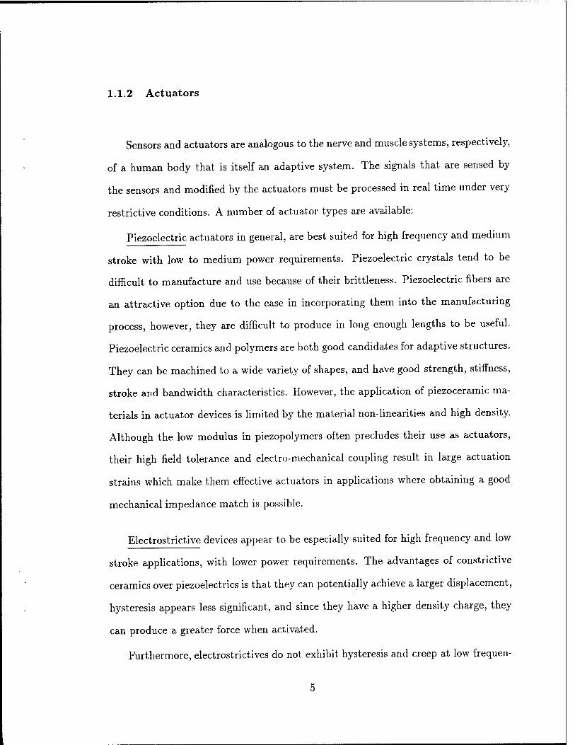
For sensing, the comparisons are conducted against the numerical simulations
performed by Ha, Keilers and Chang (1992). During this simulation, the center
row of piezoceramics were considered sensors while the outer two rows were used as
actuators. A constant voltage of 100 V was applied to one row of actuators with a
26

positive sign on the top surface and a negative sign on the bottom surface. The same
voltage was applied to the other row but in this instance the polarity was reversed,
thus inducing a twisting motion to the plate. Furthermore, a constant mechanical
load of 0.2 N was applied at the tip of the plate. Thus, the output sensor voltages
were numerically determined for the combination of electrical and mechanical loads.
Figure 2.4(e) shows good agreement between the solid brick finite element model and
the composite plate model formulations and Figure 2.4(f) shows the sensed voltages
along the central tier of piezoelectric patches.
Finally, consider the same cantilever plate with only two pairs of piezoelectric
patches located near the clamped boundary. It was of interest to determine the
amount of voltage required by the piezoelectrics to maintain a zero tip deflection of
the plate, when subjected to a concentrated load at the tip. The voltage required
to preserve the zero tip deflection as a function of the applied mechanical loading
is presented in Figure 2.5(a). It is observed that a linear relationship between the
voltage and the applied load exists. Figure 2.5(b) shows the deformation of the plate
under both the mechanical loading and the calculated electrical loading, with the
piezoelectric layers in actuation.
2.3.2 Eigenvalue Solution
The experimental apparatus used in this experiment consists of an aluminum
cantilever beam with six pairs of lead zirconate titanate (PZT) tiles attached to the
locations shown in Figure 2.6(a). This experiment was set up by Hollkamp (1994) at
the Wright Laboratory. A measurement/excitation spectrum analyzer is connected
to the structure to carry out control studies in the frequency domain. The natural
frequencies of the first three bending modes have been estimated using experimental
data. The natural frequencies are /i = 9.2, f2 = 57.5 and /3 = 160.5 Hz. The
27

finite element model used to simulate this structure is comprised of 26 elements, 195
structural degrees of freedom, and 24 electrical degrees of freedom (Figure 2.6b).
The frequencies estimated by the finite element model are /i = 9.1, h = 58.2 and
/3 = 168.3 Hz.
28

Experimental Apparatus (a)
Digital Meter
Proximeter
o o o Voltage
Amplifier/Supply
*-—Piezoelectric Bimorph Beam
Figure 2.3 (a) Test study comparison between the present formulation and Tzou
and Tseng (1990) showing the experimental apparatus for the piezo-
electric bimorph plate.
Finite Element Model
L 5 elements 53 d.o.f.
(b)
Figure 2.3 (b) Test study comparison between the present formulation and Tzou
and Tseng (1990) showing the finite element model with 53 degrees
of freedom.
29

Actuation Mechanism
xlO '7 m
(c)
Position 1 2 3 4 5
Theory 0.14 0.55 1.24 2.21 3.45
Beam FE6 0.12 0.51 1.16 2.10 3.30
Present 0.14 0.55 1.24 2.21 3.45
EXP6 - -
" - 3.15
Figure 2.3 (c) Test study comparison between the present formulation and Tzou
and Tseng (1990) showing the comparison of results for the static
actuation mechanism.
Sensing Mechanism (d)
mm
Figure 2.3 (d) Test study comparison between the present formulation and Tzou
and Tseng (1990) showing the static sensing mechanism.
30

Experimental Apparatus
DD
Gr/Epoxy [0/±45]
r- '■ ■ ■ j| "^** ^xn
B = 6in.
— L = 11.5 in A-1
W,
W<
=Uw3
-+~ (a)
Figure 2.4 (a) The experimental apparatus showing the Gr/Epoxy [0/±45] can-
tilevered plate studied by Crawley and Lazarus (1991).
Fin iteE lenient Model 1( 85
)0 elements JO d.o.f.
. 1111: 111 •;|:|: 11 lit
111 :•§:$:$>:
111 ill :|l?:?:
===§
(b)
Figure 2.4 (b) The finite element model with 880 degrees of freedom developed here
to compare the results with the model reported by Crawley and
Lazarus (1991) .
31

Actuation Mechanism
■© 1-1 K
e •
O Plate 0 Solid A Exp
(j) =± 158 Volts
Ben
ding
w
■
§ •3 8 •- 1 J 1 R I . I ■ i ■ i ■ 1
• (c)| 0 .2 .4 x/L .6 .8 1.
Figure 2.4 (c) Comparison between the present formulation results and Crawley
and Lazarus (1991) showing the results for the static actuation mech-
anism.
Actuation Mechanism
I Actuator (+158 V)
Structure
Actuator (-158 V)
Figure 2.4 (d) The deformed configuration of the cantilevered plate resulting from
the static actuation for an applied voltage of ±1581^.
32
Sensing Mechanism 8
2
I
■o 0 >
_4J
u -° Solid -o Plate
J l_ .4 x/L .6
P=0.2N V=±100
.8 1.0
Figure 2.4 (e) Comparison of the sensing voltages along the central tier of piezo-
electric elements due to voltage of ±100y applied on the outer tiers
of piezoelectrics.
Sensing Mechanism
Actuator (+100 V)
Sensor (+9 V)
Sensor C+7 V)
Sensor (+5 V)
Sensor (+3 V)
Sensor (+1 TO
Structure
Sensor (-1V)
Sensor (-3 V)
■ Sensor (-TV)
Sensor (-9 V)
Actuator (-100 V)
Figure 2.4 (f) The deformed configuration showing the sensed voltages along the
central tier of piezoelectrics.
33

> CO
§3 100 ro i—i o > o 50
■d «j 3 o
D Present O Ha, Keilers & Chang
Applied tip Load (N) 0.2
(a)
Figure 2.5 (a) Comparison between the present formulation and Ha, Keilers and
Chang (1992) showing the relationship between the required actua-
tion voltages and the various tip loading conditions.
Figure 2.5 (b) The deformed configuration of the cantilevered plate under the action
of the mechanical tip load and electric actuation.
34

Experimental Apparatus
PZT Sheet
Accelerometer
Measurement/Excitation Spectrum Analyzer
I Not to Scale (a)
Figure 2.6 (a) Eigenvalue solution comparison between the present formulation and
Hollkamp (1994) showing the experimental apparatus for the alu-
minum cantilever beam with 6 pairs of PZT tiles.
Finite Element Model 26 elements 195 d.o.f.
Figure 2.6 (b) Natural frequencies comparison between the present formulation and
Hollkamp (1994) showing the finite element model with 195 degrees
of freedom.
35

2.4 COMMERCIAL FEM CODES
A few finite element commercial codes have incorporated piezoelectric modelling
features and four codes are analyzed here and their capabilities are reported.
2.4.1 ANSYS - Swanson Analysis Systems, Inc.
In ANSYS, the piezoelectric analysis is a feature of the coupled-field analysis ca-
pability. The following finite elements are available in ANSYS (Swanson Analysis,
1986) to perform a coupled-field piezoelectric analysis: PLANE13 (the 2-D coupled-
field solid), S0LID5 (the 3-D coupled field solid), and SOLID98 (the 3-D coupled-field
tetrahedron). The analysis may be static, modal, harmonic, or transient. Other types
of coupled-field analysis are available using these elements such as thermal-stress anal-
ysis, thermal-electric analysis, electro-magnetic analysis, magnetic-structural analysis
and magnetic-thermal analysis.
To perform a piezoelectric analysis, the dielectric constant [eE] can be input by
using the MP command. Only the diagonal components of the dielectric matrix can
be input (PERX,PERY, PERZ). The TB,PIEZ and TBDATA commands are used to
define the [e] matrix. The elastic coefficient matrix [c] can be input by either using
the TB, ANEL and TBDATA commands or by using the MP,EX and MP,NUXY
commands. A typical input data card deck would have the form shown in Table 2-1.
2.4.2 ABAQUS - Hibbit, Karlsson & Sorensen, Inc.
In ABAQUS (Hibbit, Karlsson and Sorensen Inc., 1990), a fully coupled piezo-
electric analysis may be performed for continuum problems in one, two and three di-
mensions. The elements that provide this capability are the piezoelectric plane strain
elements (CPE3E, CPE4E, CPE6E, CPE8E, CPE8RE), the piezoelectric plane stress
elements (CPS3E, CPS4E, CPS6E, CPS8E, CPS8RE), all with active degrees of free-
36

Table 2-1 Input data card deck for ANSYS showing the necessary commands
to perform a piezoelectric analysis.
ANSYS INPUT DATA
/PREP7 ET.130LID5 MPJEXr.. (Young's Modulus) MPJWXY,... (Poissons Ratio) MPfERXr.. (Dielectric Matrix [e]) TB,PIEZ,1 (Piezoelectric Matrix [e]) TBDATAr.. FINISH /SOLUTION ANTYPE,STATIC DALL,UX,0,,, ,UY,UZ (Constraints) DALL,VOLT,_. SAVE SOLVE (Solution Phase) FINISH
dorn 1,2 and 9 (Ux, Uy and (f>), and the piezoelectric solid elements (C3D4E, C3D6E,
C3D8E, C3D10E, C3D15E, C3D20E and C3D20RE), with active degrees of freedom
1,2,3 and 9 (Ux, Uy, Uz and (f>). The materials electrical and electro-mechanical
coupling behaviour are defined by its dielectric property and its piezoelectric stress
property. These properties may be entered using the *PIEZOELECTRIC and *DI-
ELECTRIC cards. A typical ABAQUS data input deck would have the form shown
in Table 2-2.
2.4.3 NASTRAN(CSA) - CSAR Corporation
The piezoelectric theory in CSA-NASTRAN (CSAR Corporation, 1980) has been
incorporated into the finite element formulations of the TRAPAX and TRIAAX el-
ements. These elements, trapezoidal and triangular in cross-section respectively, are
solid, axisymmetric rings whose degrees of freedom are expanded into Fourier se-
37

Table 2-2 Input data card deck for ABAQUS showing the necessary commands
to perform a piezoelectric analysis.
ABAQUS INPUT DATA
♦NODE, NSET=TOP (Input Nodal Coord.) »ELEMENT, TYPE=C3D20E,
ELSET=PID1 »SOLID SECTIONJELSET=PIDl,
MATERIAL=PVDF
»MATERIAL, NAME=PVDF
»ELASTIC, TYPE=ISO »PIEZOELECTRIC, TYPE=S •DIELECTRIC, TYPE=ISO »STEP, PERTURBATION •STATIC (Solution Phase) »BOUNDARY (Constraints)
ries, thus allowing non-axisymmetric loads. The degrees of freedom per node are the
radial, tangential and axial displacements and the electric potential.
Piezoelectric modelling requires the specification of a parameter on the NAS-
TRAN card as well as the use of up to four bulk data cards. The NASTRAN card
allows the user to override various NASTRAN system parameters by denning specific
words in the /SYSTEM/ COMMON block. The 78th word of /SYSTEM/, that is,
SYSTEM(78), has been set aside to indicate the use of piezoelectric materials. The
default value for SYSTEM(78) is zero, implying that no piezoelectric materials are
allowed. If SYSTEM(78) = 1, piezoelectric materials are allowed and coupling occurs
between the structural and electrical degrees of freedom.
There are four BULK DATA cards that pertain specifically to piezoelectric mod-
elling. MATPZ1 and MATPZ2 describe the piezoelectric material properties in two
different ways. MATPZ1 is used to specify parameters for the permittivity constants
38

[e], piezolectric constants [d] and structural constants [SE] for an isotropic piezoelec-
tric material, and MATPZ2 describes material constants for anisotropic materials.
2.4.4 NASTRAN(MSC) - The MacNeal-Schwendler Corp.
MSC-NASTRAN (The MacNeal-Schwendler Corp., 1990) does not contain struc-
tural piezoelectric modelling capabilitites in the same context as presented in the
other commercial finite element codes. In other words, there are neither coupled-
field finite elements as in ANSYS nor explicit piezoelectric structural elements as in
ABAQUS.
2.4.5 Simulation Results
In order to assess the capabilities reported in the manuals for ANSYS and ABAQUS,
the bimorph cantilevered beam proposed by Tzou (1987) has been selected. The
objective here is to model this structure and compare the response by using the
coupled-filed analysis in ANSYS and the piezoelectric elements in ABAQUS. The
tip deflections due to an applied voltage of 1 V across the thickness are compared
to the solutions obtained by the QUAD4-type (Venkayya and Tischler, 1992) plate
formulation developed here.
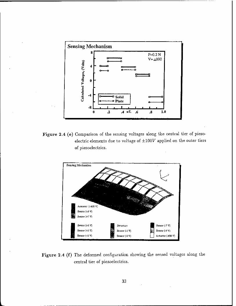
The model developed for ANSYS consists of SOLID5 elements, the three dimen-
sional coupled-field solid elements. This element has eight nodes with four degrees of
freedom per node (UX, UY, UZ, VOLT). The tip displacement predicted by ANSYS
using solid brick elements was 3.45E-7 m, which agrees exactly with the tip displace-
ment predicted by theory and the laminated plate theory. However, while only 5
plate type elements were used in the plate finite element model with 55 degrees of
freedom, the ANSYS model required 100 solid brick type elements with 675 degrees
of freedom.
39
Example Problem
czodcctrlc Blmorph Beam
ACTUATION = +0.5 V top layer/-0.5 V bottom layer
PRESENT FORMT!I,ATION/OUAD4
No. of elements = 5 No.ofDOF = 53 Tip Deflection = 3.45e-7 m
Deformed Shape
ANSYS/SOLID5
No. of elements = 100 No.ofDOF = 675 Tip Deflection = 3.45e-7 m
ABAOTTS/C3D20E
No. of elements = 250 No.ofDOF = 1620 Tip Deflection = 3.44e-7 m
Figure 2-7 Comparison between the solid element models developed in ANSYS
and ABAQUS and the composite plate element developed here.
In ABAQUS, the cantilevered plate was modelled using C3D20E elements. Since
the elements developed in ABAQUS are based on a single point integration, more
elements were required to model the structure. Here, 250 solid elements were used
resulting in 1620 degrees of freedom. The tip deflection obtained due to the actuation
of IV was 3.44E-7 m.
Figure 2-7 shows the example problem used here, the deformed configuration
in the presence of actuation and the tip deflection results for the three models for
ANSYS, ABAQUS and laminated plate theory.
2.5 THERMAL ANALOGY
Since thermal and piezoelectric strains are both induced strains, the piezoelectric
induced strains can be handled in the same manner as thermal strains. The piezoelec-
tric material was assigned a coefficient of thermal expansion along with other material
40

properties such as Young's modulus. The combination of the thermal expansion co-
efficient multiplied by the change in temperature, the thermal strain, was set equal
to the actuation strain of the piezoelectric material, i.e.
aAT = [d\{E}
where the piezoelectric strain is a combination of the piezoelectric constant [<f] mul-
tiplied by the electric field strength {E}.
Here, as an example, the same beam proposed by Tzou (1987) has been used.
The thermal model was developed in ANSYS using SOLID70 thermal elements. The
thermal loads equivalent to the applied voltages resulted in a temperature distribution
of ±0.75°C along the top and bottom walls of the plate, and an applied temperature
of ±0.25°C along the inner walls (Figure 2-8). This is equivalent to applying a voltage
differential of +0.5V across the top layer and a voltage of —0.5V across the bottom
layer. It is observed that identical tip deflections are produced by both methods. It
should be noted that the thermal loads can only be used in the context of actuation,
as they are unable to simulate the converse effect found in piezoelectrics.
2.6 PRELIMINARY REMARKS
A new finite element formulation has been developed to analyze the electro-
mechanical behaviour of laminated composite structures containing distributed piezo-
electric actuators and sensors. This new Mindlin-type piezoelectric plate formulation
has been implemented and its performance has been evaluated. Based on this study,
the following remarks can be made:
(i) The numerical results generated by the electromechanical finite element plate
model simulations agree well with experimental data and solid element formula-
tions reported in the literature;
41

Example Problem
ezoelectrlc Blmorph Beam
ACTUATION = +0.5 V top layer/-0.5 V bottom layer
PIEZO STRAIN = THERMAL STRAIN
Young's Modulus Coefficient of Thermal Expansion jC
-a =ei3/Y/fr -Thickness
Piezoelectric Constant
THERMAL I
ANSVS/SOUD70 Thermal Solution
No. of elements = 100 No.ofDOF = 675 Tip Deflection = 3.45e-7 m
PRESENT FORMIJLATION/OÜAP4 Piezoelectric Solution
No. of elements = 5 No.ofDOF = 53 Tip Deflection = 3.45e-7 m
Figure 2-8 An example to establish the analogy between the thermal and piezo-
electric behaviour.
(ii) the finite element model based on the Mindlin plate formulation with one electrical
degree of freedom per piezoelectric layer is much simpler to formulate and more
computationally efficient than models based on solid element formulations, where
the number of degrees of freedom used to model the problem is significantly larger;
(ii) a few commercial finite element codes have the capability to model piezoelectric
materials. However, only modelling using solid elements is available in these codes
to the user resulting in models with a very large number of degrees of freedom,
as demonstrated by an example;
(iv) the analogy between thermal and piezoelectric behaviour has been established by
equating the thermal and piezoelectric strains.
42

CHAPTER
THREE
APPLICATION - FLUTTER CONTROL
Panel flutter is a self-excited, dynamic instability of thin plate or shell-like com-
ponents of flight vehicles. It depends upon diverse factors such as Mach number, flow
angle with respect to the panel, support conditions, curvature, in-plane stress and
cavity effects, to name a few. It occurs most frequently in supersonic flow although,
in subsonic flow, it can take the form of static divergence.
3.1 DESIGN PROBLEM
Consider a thin composite rectangular flat panel of length a, width 6, and of
uniform thickness h, mounted on a rigid wall as shown in Figure 3.1. The upper
surface of the plate is exposed to a high supersonic airflow, at zero angle of attack
and parallel to its side edges. Beneath the plate still air is present. In the presence
of some disturbance, the plate can start to perform a perturbed motion with lateral
deflection. We are interested in the study of the stability of such plate motion, called
flutter, and investigate the feasibility of applying piezoelectric actuators to control it.
Traditionally, these panels are designed for flutter by applying conventional methods
of motion suppression such as thickening and reshaping the panels.
In adaptive structures research, considerable work has been carried out to investi-
gate the feasibility of using piezoelectric materials to suppress vibration in structural
systems. However, in the area of control of panel flutter, only a few research papers
based on analytical solution methods have been reported (Scott and Weisshaar, 1991;
43

Aerodynamic Pressure (lst-order Piston Theory)
Air Flow
Panel Length a
Figure 3.1 Self excited oscillations of an external panel of a flight vehicle exposed
to supersonic air flow (M > Vz)
Heeg, 1992; and Lai et. al, 1994).
Before attempting to use piezoelectric materials in panel flutter control problems,
a knowledge of the degree of control authority exhibited by a typical piezoelectric
actuator needs to be quantified.
Table 3.1 shows the material properties and operating conditions for a G1195 PZT
piezoceramic. Relationships between the applied forces and the resultant responses
depend upon the piezoelectric properties of the material, the size and shape of the
patch and the direction of the electrical and mechanical excitation. For example,
consider a typical piezoceramic patch with dimensions 5 x 5 x 0.05 cm. The stress free
length change in the in-plane direction can be expressed as AL = d^xEa = 6.6/zm,
where E, the electrical field, is the applied voltage per unit length. The strain free force
in the in-plane direction due to an applied voltage of 400 V is F = YdziEbh = 200 N.
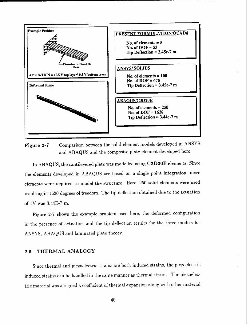
Table 3-2 shows the actuation capabilities and the power requirements for an applied
voltage of 400 V at 10 Hz.
The question that needs to be raised now is the piezoceramic patch capable of
44

Table 3-1 Material properties and operating conditions for a G1195 PZT piezo-
ceramic.
PIEZOCERAMIC - G1195
pm/V Piezoelectric Charge Coefficient (d31) = 166
Eleastic Modulus (Y) = 63 GN/m
Capacitance (C) = 90 nF
Curie Temperature = 360 °C
Maximum Electrical Field (E) = 2.0 MV/m
Density = 7650 Kg/m3
generating a significant force output in order to affect the stiffness of the panel, and
thus push back the flutter boundary envelope. Figure 3-2 shows the effect that in-
plane loads have on the flutter boundary. Tensile loading, which can be generated
by piezoelectric actuators, causes the flutter boundary to shift considerably. For
example, for a simply-supported panel with dimensions 30 x 30 x 0.1 cm, the range
of in-plane force that affects the coalescence of the first mode lies in the 200 to 2,000
N range (Nasr-Bismarck, 1992). Therefore, it can be inferred that an arrangement of
piezoelectric patches where each exerts an in-plane force of approximately 200 N, due
to an applied voltage of 400 V, is capable of significantly affecting the panel flutter
characteristics.
45
Table 3-2 The actuation capabilities and power requirements for a typical piezo-
ceramic patch.
CAPABTT JTTES ANn REQUIREMENTS
Piezoceramic Patch = 5.0 x 5.0 x 0.05 cm
Stress Free Length Change = 6.6 fim
Strain Free Force = 200 N
Moment Generated = 0.3 Nm
Electrical Current = 2.0 mA
Electrical Power = 1.0 W
Electrical Charge = 36 JiC
3.2 PANEL FLUTTER MODEL
In the supersonic regime, above a Mach number of about \/2, simple approxi-
mations for the aerodynamic forces such as piston theory, give satisfactory results
(Bisplinghoff, Ashley and Halfman, 1955).
3.2.1 First Order Piston Theory
Piston theory gives the following simple relation between pressure and motion
(Bismarck-Nasr, 1992)
. rdw dw-.
dt dx (3.1)
In the above relation we assume that the deflection is zero at the panel's leading and
trailing edges. The work done by the aerodynamic surface pressure can be calculated
46

APPLICATTON: PA NET. FLUTTER
FLUTTER BOUNDARIES (Bismarck-Nasr, 1992)
a =0.3
b = 0.3
h = l
m
m
mm
E = 6.9e7 N/m
v = 0.3
Nx = 200 -^2000
~Kx = NXua'lir'D
Figure 3.2 Effect of in-plane tensile forces
by the principle of virtual work:
W = - [!B-( L ^rdw M2
V—+ 2dw
AVß\ dx M2 - 1 dt wdA (3.2)
where Q = pV2/2 is the free stream dynamic pressure, ß = \fM2 — 1, V is the free
stream velocity, M is the free stream Mach number, and p^ is the air density.
Substituting Equation (3.2) into Hamilton's equation, we obtain the following
aerodynamic damping and stiffness matrices for each element:
AJ; [=g f NTNd A, JA
j = l,...,ne/;
47
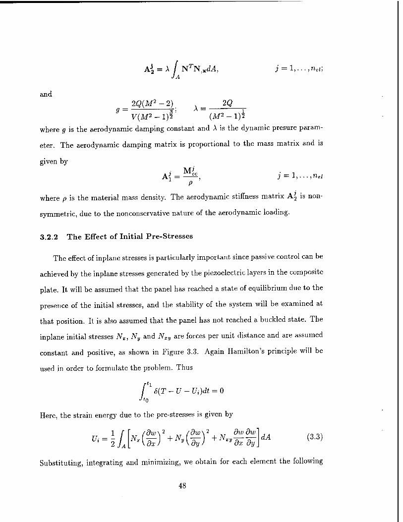
AJ2 = A / NTN X<L4, j = 1, • • •, ne/;
JA
and _ 2Q(M2-2)_ A_ 2Q
y(M2-l)f (M2-l)2
where # is the aerodynamic damping constant and A is the dynamic presure param-
eter. The aerodynamic damping matrix is proportional to the mass matrix and is
given by
A^ = ——, j = l,...,nel
P
where p is the material mass density. The aerodynamic stiffness matrix A2 is non-
symmetric, due to the nonconservative nature of the aerodynamic loading.
3.2.2 The Effect of Initial Pre-Stresses
The effect of inplane stresses is particularly important since passive control can be
achieved by the inplane stresses generated by the piezoelectric layers in the composite
plate. It will be assumed that the panel has reached a state of equilibrium due to the
presence of the initial stresses, and the stability of the system will be examined at
that position. It is also assumed that the panel has not reached a buckled state. The
inplane initial stresses Nx, Ny and Nxy are forces per unit distance and are assumed
constant and positive, as shown in Figure 3.3. Again Hamilton's principle will be
used in order to formulate the problem. Thus
rh / S(T-U- Ui)dt = 0
Here, the strain energy due to the pre-stresses is given by
1 /" r /dw\2 ,T /dw\2 Ar dwdw' dA (3.3)
Substituting, integrating and minimizing, we obtain for each element the following
48

geometric stiffness matrix:
Kj = NX f N,x.TN,xdA + Ny f N,yTN,ydA JA JA
+ Nxy I N, xTN, ydA + Nxy [ N, yTN, xdA; j = 1,..., ne/ (3.4) JA JA
Nxy 7///
Figure 3.3 Initial in-plane pre-stresses on the panel due to piezoelectric actuation.
3.2.3 Equations of Motion
For the entire structure, using the standard assembly technique for the finite
element method and applying the appropriate boundary conditions, we obtain the
equations of motion for a composite panel with piezoelectric layers in a supersonic
flow field
Inertia Elastic Stiffness Aero Damping
Ai 0 0 0
Ü ^. e u - > +
Geometric Stiffness
Kg 0 0 0
üc
ue = 0
49

3.3 PASSIVE CONTROL
First, let us examine the development of nutter in the panel, in the absence of any
piezolectric actuation. The panel, made of aluminum with the properties as shown in
Figure 3-2, is simply supported along all four of its sides. Sixty-four finite elements
with 309 structural degrees of freedom are used to model the plate. As the dynamic
pressure increases, the natural frequencies of the first and second modes get closer
(Figure 3-4), until they coalesce, and the dynamic pressure A at this point is called
the critical dynamic pressure. For this particular panel, neglecting the aerodynamic
damping effect, the critical dynamic pressure parameter is 38.8 psi. After coalescence
of the first two modes, the imaginary parts of the eigenvalues become split, one
towards the negative side, and the other towards the positive side. When A passes the
critical point, the system becomes inherently unstable, such that a small disturbance
makes the amplitude of the panel deflection diverge. As A increases further, the third
and fourth modes coalesce as well. The fundamental mode shape in a vacuum and
following the onset of flutter is also shown in Figure 3-4.
Using the passive control methodology, the flutter velocity of panels, or similarly
the critical dynamic pressure, can be increased by making piezoelectric actuators
induce in-plane tensile forces which alter the effective stiffness of the panel. This
strategy is depicted in Table 3-3. The same voltage is applied to the the top and
bottom piezoelectric layers, resulting in uniform compression or tension in the plate.
This static loading condition on the panel induces in-plane stresses Nx, Ny and Nxy.
These stresses are subsequently used to calculate the geometric stiffness of the plate,
which couples the in-plane and transverse motions of the panel. Subsequently, the
geometric stiffness matrix is added to the linear stiffness matrix, and the eigenvalue
problem is solved. The value for A at which a complex solution exists is considered to
50

VARIATION OF SYSTEM ROOTS vs TWNAMIC PRESSURE
1.5 p— : ; "- k« ~^\- ^^-^^^' "K
1.0
_^J>^^ K^ /^-
o
^^K /^K
■=- 0.5 CD
CO > 8
^\£n
-0.5 ' n K~~~~~~-~. ~~-~^^
500 1000
Aerodynamic Parameter x
Figure 3.4 The natural frequencies solution as a function of dynamic pressure.
The fundamental mode shapes are shown in vacuum and following
the onset of flutter.
be the onset of flutter. When the piezoelectric patches create a state of tension in the
panel, the dynamic pressure increases. If the piezoelectric patches exert compressive
forces on the panel, the dynamic pressure decreases.
Now, let us examine a passive actuation configuration in which the piezoelectric
patches cover the center of the plate (Figure 3-5). First, consider a case where the
patches cover only 6% of the plate area. Here, the mass increases by 17% due to
the addition of the piezo patches to the base structure. Obviously, the effective
stiffness also increases. It was observed that the critical dynamic pressure increased
from 36.8 to 46.9, an improvement of 27%. Note that this increase is solely due to
the bonding of the piezo patches to the top and bottom surfaces of the aluminum
51

Table 3-3 Passive control methodology flowchart.
(7 ACTUATION
Kuu U = "**„(), 0
V u > i CALCULATE PRE-STRESS LOAD VECTOR
CJ Nx, Ny, Nxy
[ \ \A GEOMETRIC STIFFNESS MATRIX
^7 /~7
Kg = NXJNJS. N,X dA + Ny/N,y N,y dA + NxyJ NJC N,y dA + NyxjN,y N,x dA
/ / L FIND NEW CRITICAI. A.
^ MUUÜ +[KUU +Kg+>tA] U =0
panel. Subsequently, the piezo patches were actuated with a voltage of 400 V and,
in this instance, a further increase of 42% was attained, relative to the case where no
voltage was applied. Summarizing, a better performance was indeed attained by the
piezoelectric actuation. The effective stiffness was increased by merely attaching the
piezo patches in the first instance, and a further increase was obtained by actuating
the piezo patches with an applied voltage.
Next, the performance of a patch which covered 25% of the plate area was as-
sessed. Here, a substantial increase in mass was observed (69%). The addition of
piezo patches with no voltage applied resulted in an increase of 92% in dynamic pres-
sure. Further application of 400 V across each layer resulted in a smaller further
52

improvement in dynamic pressure to 93.5, or 32% relative to the 0 V case. Thus, it
is noted that an increase in size of the piezo patches and/or actuation power, does
not necessarily result in better performance. In fact, the 25% patch configuration
performed worse than the 6% patch case. Apparently, the larger piezo patch config-
uration resulted in a relatively much larger mass increase thus offsetting the benefits
of an increased actuation capability.
Three more patch configurations have been analyzed to further probe this matter.
Let us call these configurations 1, 2 and 3, as shown in Figure 3.6. In configuration 1,
five piezo patches are placed in a star shaped form, resulting in a mass increase of 86%.
The flutter dynamic pressure, in the presence of an applied voltage of 400 V, exhibits
a poor performance with a mere 5% increase in value relative to the no applied voltage
case. In other words, a larger actuation capability, followed by a much larger mass
increase resulted in a negligible improvement. For configuration 2, with 4 piezoelectric
patches arranged in a cross shape, the mass increased by 69%. The resultant critical
dynamic pressure increased by 8% to 99.2 due to an applied voltage of 400 V. Finally,
configuration 3 with the piezo patches arranged along the perimeter of a square at
the centre of the plate, exhibited an increase of 20% in dynamic pressure, with an
increase of 52% in mass. Thus, in configuration 3, a better performance was attained
in the presence of a relatively smaller increase in mass, while in configuration 1, a
poor performance was exhibited with a substantial increase in mass.
Another aspect that draws attention is the fact that the 25% central patch config-
uration and the number 2 configuration provide a similar mass increase (69%). How-
ever, the 25% central patch configuration resulted in a 32% improvement in dynamic
pressure, while the actuation in configuration 2 exhibited a poor 8% improvement.
On a preliminary analysis basis, it can be inferred that not only is the added mass to
53

stiffness ratio important, but also the configuration and placement of the patches on
the structure should be taken into account during the design process.
Summarizing, there is an optimum patch size, and there in an optimal patch
configuration which deliver the best performance. A compromise needs to be found
between the advantages of an increased actuation capability and the disadvantages
of an increased weight due to the addition of piezoelectric material. These questions
need to be addressed through formal optimization design procedures.
3.4 PRELIMINARY REMARKS
The feasibility of employing piezoelectric actuators to control panel flutter is
investigated. The panel is an aluminum simply supported plate with piezoelectric
patches bonded to the top and botton walls of the structure, in various configurations.
Here, a passive control methodology is proposed, where the top and bottom layers
are subjected to identical voltages. The actuation stiffens the plate. Based on the
simulations, the following can be inferred:
(i) Flutter control using piezoceramics is dependent on the mass to stiffness ratio
and on the configuration and placement of the patches;
(ii) the application of piezoceramics as actuation devices in panel flutter problems
may be limited by its high material density; and
(iii)formal optimization design procedures need to be invoked in order to address the
issue of optimal actuator size, shape and placement.
54

SYSTEM CONFIGURATION Critical Aerodynamic Parameter (Aluminum Panel Substructre)
A,crit = 36.8
A.«« = A-ciit a /D = 512
Critical Aerodynamic Parameter A. crit
Applied Voltage 6% Patch 25% Patch
• V 46.9 70.5
200 V 57.0(21%) 81.6 (16%)
400 V «4.7 (42%) 93.5 (32%)
Mass 1 +17% +69% |
Figure 3.5 Critical dynamic pressure results for a central piezoelectric patch con-
figuration for two sizes of actuation capabilities.
CONFIGURATION #1 CONFIGURATION #2 | CONFIGURATION #3
&z
Base Panel
OV
400 v
3ti.8
88.5
92.5
A. crit increase
mass increase
5%
86%
I
Base Panel
0V
400 v
A. crit increase
mass increase
>-crit
36.8
91.8
99.2
8%
■69%
n
^crit increase
mass increase
^crft
Base Panel 36.8
OV 63.9
400 v 76.5
20%
•52%
Figure 3.6 Critical dynamic pressure results for three different patch configura-
tions.
55

CHAPTER
FOUR
CONCLUDING REMARKS
The possibility of employing adaptive materials to control panel flutter has been
considered. First, a simple finite element formulation for a composite plate with
laminated piezoelectric layers is presented. Classical laminate theory with electrome-
chanical induced actuation and sensing and variational principles are used to formu-
late the equations for a Mindlin plate finite element based upon uniformly reduced
integration and hourglass stabilization. The equations of motion are discretized with
four node, 24 degree of freedom quadrilateral shell elements with one electrical degree
of freedom per piezoelectric layer. Based on this study, the following remarks can be
made:
(i) The numerical results generated by the simple and efficient finite element de-
veloped here agree well with experimental data and solid element formulations
reported in the literature;
(ii) the finite element model based on the single point integration Mindlin plate formu-
lation and one electrical degree of freedom per piezoelectric layer is much simpler
to formulate and more computationally efficient than models based on solid el-
ement formulations, where the number of degrees of freedom used to model the
problem is significantly larger.
Next, the feasibility of employing the piezoelectric effect to control panel flutter
is investigated. The panel is an aluminum simply supported plate with piezoelectric
patches bonded to the top and bottom walls of the structure, in various configurations.
56

Here, a passive control methodology is proposed, where the top and bottom piezoelec-
tric patches are subjected to identical voltages. The actuation voltage contracts the
plate, stiffening it. The resultant stresses are used to calculate the geometric stiffness
matrix. Based on the simulations, the following can be inferred:
(i) The critical aerodynamic parameter, defined as the value at which the eigenvalues
become complex, increases considerably due to the added mass of the piezoelectric
patches. However, a maximum 42% increase in the aerodynamic parameter was
attained due to an applied voltage of 400 V at the top and bottom layers in a
patch which covered 6% of the plate area,
(ii) It was further observed that flutter control is dependent on the mass to stiffness
ratio, and on the placement and configuration of the piezoelectric patches.
(iii)The application of piezoceramic materials as actuator devices in panel flutter
problems may be limited by the material high density.
(iv) Formal optimization design procedures need to be invoked to address the issue of
optimum actuator size and placement in order to attain optimal performance.
57

REFERENCES
Anders, W.S., Rogers, CA., 1990, "Vibration and Low Frequency Acoustic Anal- ysis of Piecewise Activated Adaptive Composite Panels", 1st Joint US-Japan Con- ference on Adaptive Structures, Maui, Hawaii, USA:285-303.
Belvin W.K., Edighoffer, H.H., and Herstrom, C.L., 1989, "Quasistatic Shape Ad- justment of a 15-meter Diameter Space Antenna", Journal of Spacecraft, 26(3): 129-
136.
Belytschko, T., Lin, J.I., and Tsai, C.S., 1984, "Explicit Algorithms for the Non- linear Dynamics of Shells", Comp. Meth. Appl. Mech. Engng., 42:225-251.
Belytschko, T., Tsay, C.S., and Lin, J.I., 1981, "A Stabilization Matrix for the Bilinear Mindlin Plate Element", Comp. Meth. Appl. Mech. Engng., 29:313-327.
Belytschko, T., and Tsay, C.S., 1983, "A Stabilization Procedure for the Quadri- lateral Plate Element with One-point Quadrature", Int. J. Num. Meth. Engng.,
19:405-419.
Bisplinghoff, R.L., Ashley H., and Halfman, R.L., 1955, "Aeroelasticity", Addison- Wesley Publishing Co.
Breitbach, E.J., 1991, "Research Status on Adaptive Structures in Europe", Sec- ond Joint Japan-US Conference on Adaptive Structures", Nagoya, Japan, 32-48.
Brockman, R.A., Lung, F.Y., and Braisted, W.R., 1989, "Probabilistic Finite Element Analysis of Dynamic Structural Response", Air Force Wright Aeronautical Laboratories, AFWAL-TR-88-2149.
Crawley, E.F., and de Luis, J., 1985, "Use of Piezoceramic as Distributed Ac- tuators in Large Space Structures", Proceedings of the AIAA/ASME/ASCE 26th Structures, Structural Dynamics, and Materials Conference, Part 2:126-133.
Crawley, E.F., and de Luis, J., 1991, "Experimental Verification of Piezoelectric Actuators for Use in Precision Space Structures", AIAA Paper No. 83-0878.
Crawley, E.F., and Lazarus, K.B., 1991, "Induced Strain Actuation of Isotropie and Anisotropie Plates", AIAA Journal, 29(6):944-951.
Elhers, S.M., and Weisshaar, T.A., 1990, "Static Aeroelastic Behaviour of an Adaptive Laminated Piezoelectric Composite Wing", Proceedings of the 31st Struc- tures, Dynamics and Materials Conference, Long Beach, CA.
58

Flanagan, D., and Belytschko, T., 1981, "A Uniform Strain Hexahedron and Quadrilateral with Orthogonal Hourglass Control", Int. J. Num. Meth. Engng., 17:679-706.
Gardiner, P, Culshaw, B., McDonach A., Michie, C, Pethrick, R., 1991, "Smart Structures Research Institute - Activities, Plans and Progress", 2nd Joint Japan-US Conference on Adaptive Structures, Nagoya, Japan:49-58.
Ha, S.K., Keilers, C, and Chang, F.-K., 1992, "Finite Element Analysis of Com- posite Structures Containing Distributed Piezoceramic Sensors and Actuators" AIAA Journal, 3O(3):772-780.
Hall, S.R., Crawley, E.F., How, J.P., Ward, B., 1991, "Hierarchic Control Archi- tecture for Intelligent Structures", J. of Guidance, Control, and Dynamics, 14(3):503- 512.
Heeg, J., 1992, "An Analytical and Experimental Investigation of Flutter Sup- pression via Piezoelectric Actuation", Proceedings of the AIAA Dynamics Specialist Conference, Dallas, TX:237-247.
Hollkamp, J.J., 1994, "Multimodal Passive Vibration Suppression with Piezoelec- tric Materials and Resonant Shunts". J. Intel. Mat. Sys. and Struct., 5(l):49-57.
Hughes, T.J.R., Cohen, M., and Haroun, M., 1978, "Reduced and Selective Inte- gration Techniques in Finite Element Analysis of Plates", Nucl. Eng. Des., 46:203- 222.
Hughes, T.J.R., Tezduyar, T.E., 1981, "Finite Elements Based upon Mindlin Plate Theory with Particular Reference to the Four-Node Bilinear Isoparametric El- ement", J. Appl. Mech., 48:587-596.
Jones, R.M., 1975, Mechanics of Composite Materials, Scripta Book Co., Wash- ington, D.C.
Kosloff, D., and Frazier, G., 1978, "Treatment of Hourglass Patterns in Low Order Finite Element Codes", Num. Anal. Meth. Geomech., 2:52-72.
Lai, Z., Xue, D.Y., Huang, J.-K., and Mei, C, 1994, "Nonlinear Panel Flutter Suppression with Piezoelectric Actuation", paper submitted to J. Intel. Mat. Sys. and Struct.
Lazarus, K.B. and Napolitano, K.L., 1993, "Smart Structures, an Overview", Wright Laboratory, Report No. WL-TR-93-3101.
Lazarus, K.B., Crawley, E.F., and Bohlman, J.D., 1990, "Static Aeroelastic Con- trol Using Strain Actuated Adaptive Structures", 1st Joint US-Japan Conference on Adaptive Structures, Hawaii, USA:197-226.
59

Lee, C.K., 1990, "Theory of Laminated Piezoelectric Plates for the Design of Distributed Sensors/Actuators. Part I: Governing Equations and Reciprocal Rela- tionships", J. Acoust. Soc. Am., 87(3):1144-1158.
Lin, R.R., 1990, "Active Vibration Control of Rotorbearing Systems Utilizing Piezoelectric Pushers", Ph.D. Dissertation, Texas A & M University.
MacNeal, R.H., 1978, "A Simple Quadrilateral Shell Element", Comp. Struct, 8:175-183.
Matsubara, T., Yamamoto, H., Misumoto, H., 1989, "Chatter Suppression by Using Piezoelectric Active Dampers", Rotary Machinery Dynamics, DE-18-l:79-83.
Mindlin, R.D., 1951, "Influence of Rotary Inertia and Shear on the Bending of Elastic Plates", J. Appl. Mech, 18:1031-1036.
Miura, K., Natori, M.C., 1991, "Aerospace Research Status on Adaptive Struc- tures in Japan", 2nd Joint Japan-US Conference on Adaptive Structures, Nagoya, Japan:3-14.
Mitsugi, J., Yasaka, T., Miura, K., 1990, "Shape Control of Tension Truss An- tenna", AIAA Journal, 28(2):316-322.
Nasr-Bismarck, M.N., 1992, "Finite Element Analysis of Aeroelasticity of Plates and Shells", Appl. Mech. Rev., 45(12):461-482.
Natori, M., Murohashi, S., Takahara, K., and Kuwao F., 1989, "Control of Truss Structures Using Member Actuators with Latch Mechanism", The Winter Annual Meeting of the ASME, San Francisco, CA:69-75.
Palazzolo, A.B., Lin, R.R., Kascak, A.F., Montague, J., Alexander, R.M., 1989, "Piezoelectric Pushers for Active Vibration Control of Rotating Machinery", ASME Journal of Vibration, Acoustics, Stress, and Reliability in Design, 111:298-305.
Park, K.C., Stanley, CM., Flaggs, D.L., 1985, "A Uniformly Reduced, Four- noded C° Shell Element with Consistent Rank Corrections", Comp. Struct., 20:129- 139.
Scott, R.C., and Weisshaar, T.A., 1991, "Controlling Panel Flutter Using Adap- tive Materials", Proceedings of the 32nd Structures, Structural Dynamics, and Mate- rials Conference, Baltimire, MD:2218-2229.
Tabata, M., Yamamoto, K., Inoue, T., Noda, T., Miura, K.,1991, "Shape Ad- justment of a Flexible Space Antenna Reflector", 2nd Joint Japan-US Conference on Adaptive Structures, Nagoya, Japan: 393-405.
Taylor, R.L., 1979, "Finite Element for General Shell Analysis", 5th Intl. Seminar on Computational Aspects of the Finite Element Method, Berlin.
60

Tzou, H.S., 1987, "Active Vibration Control of Flexible Structures via Converse Piezoelectricity", Developments in Mechanics, 14-c: 1201-1206.
Tzou, H.S., and Gadre, M., 1989, "Theoretical Analysis of a Multi-layered Thin Shell with Piezoelectric Shell Actuators for Distributed Vibration Controls" Journal of Sound and Vibration, 132:433-450.
Tzou, H.S., and Tseng, C.I., 1990, "Distributed Piezoelectric Sensor/Actuator Design for Dynamic Measurement /Control of Distributed Parameter Systems: a Piezoelectric Finite Element Approach", Journal of Sound and Vibration, 138(1):17- 34.
Venkayya, V.B., and Tischler, V.A., 1989, "QUAD4 Seminar" Wright Research and Development Center, WRDC-TR-89-3046.
Wada, B.K., 1991, "Application of Adaptive Structures for the Control of Truss Structures", 2nd Joint Japan-US Conference on Adaptive Structures, Nagoya, Japan:123- 131.
Wang, B.T., and Rogers, CA., 1991, "Modelling of Finite-Length Spatially Dis- tributed Induced Strain Actuators for Laminate Beams and Plates", J. Intel. Mat. Sys. and Struct, 2(l):38-58.
Whitney, J.M., 1973, "Shear Correction Factors for Orthotropic laminates under Static Load", J. Appl. Mech., 40:302-304.
Zienkiewicz, O.C., 1977, The Finite Element Method, McGraw-Hill Co., New York.
61
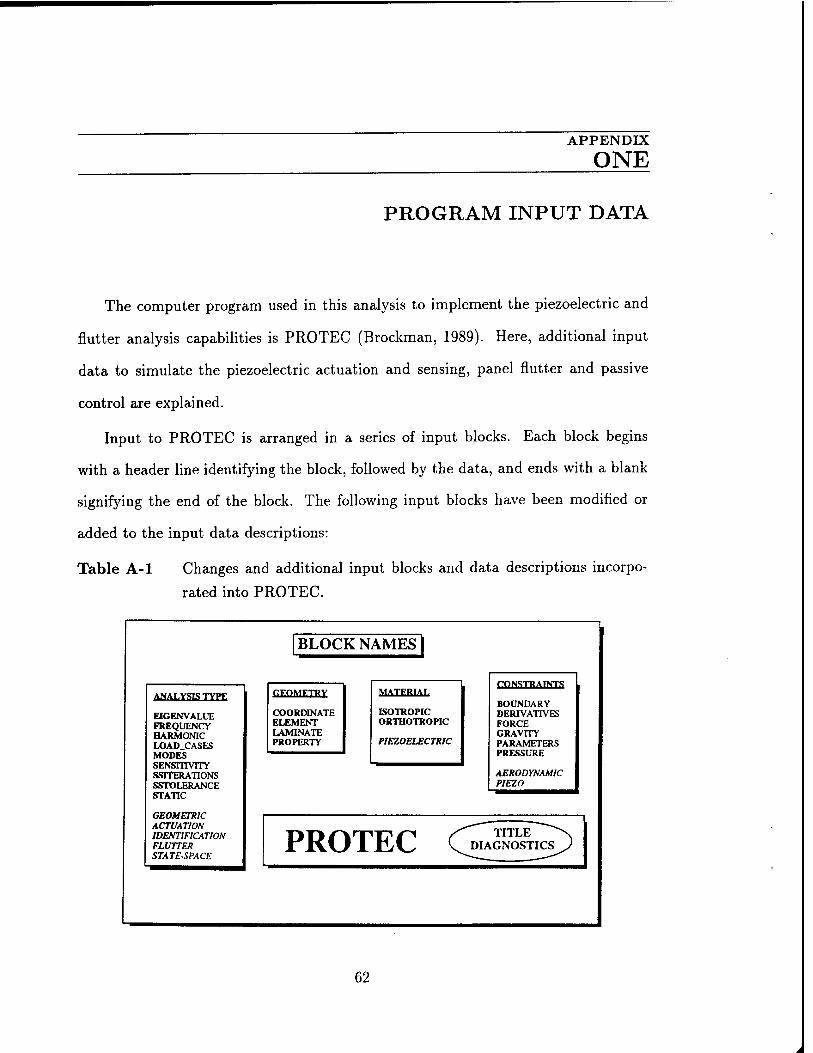
APPENDIX
ONE
PROGRAM INPUT DATA
The computer program used in this analysis to implement the piezoelectric and
flutter analysis capabilities is PROTEC (Brockman, 1989). Here, additional input
data to simulate the piezoelectric actuation and sensing, panel flutter and passive
control are explained.
Input to PROTEC is arranged in a series of input blocks. Each block begins
with a header line identifying the block, followed by the data, and ends with a blank
signifying the end of the block. The following input blocks have been modified or
added to the input data descriptions:
Table A-l Changes and additional input blocks and data descriptions incorpo-
rated into PROTEC.
ANALYSIS TYPE
EIGENVALUE FREQUENCY HARMONIC LOAD_CASES MODES SENSITIVITY SSITERATIONS SSTOLERANCE STATIC
GEOMETRIC ACTUATION IDENTIFICATION FLUTTER STATE-SPACE
BLOCK NAMES
GEOMETRY
COORDINATE ELEMENT LAMINATE PROPERTY
MATERIAL
ISOTROPIC ORTHOTROPIC
PIEZOELECTRIC
CONSTRAINTS
BOUNDARY DERIVATIVES FORCE GRAVITY PARAMETERS PRESSURE
AERODYNAMIC PIEZO
PROTEC
62

AERODYNAMIC Input block: Aerodynamic dynamic pressure for nutter anal-
ysis.
Header: Format:
(1)
AERO
For flutter analysis to find critical dynamic pressure
10 20 30
I LAMO I
40
LAMF INC CONST
Variables:
LAMO LAMF INC CONST D a
Initial guess for critical dynamic pressure Final guess for critical dynamic pressure Incremental step during iteration Non-dimensionalizing parameter a**3/D Bending rigidity of plate Plate length
63

MATERIAL Input block: Material properties data for piezoelectrics.
Header: Format:
(1)
MATE
For isotropic materials (one line/material)
5 10 20 30 40 50
I MAT I XNU I RHO I SY
(2) For orthotropic materials (two lines/material)
5 10 20 30 40 50
MAT I I
El RHO I
E2 Cl
XNU12 I 01 I
G12 I
(2)
Variables:
60 70
I G13 I
G23 I
For piezoelectric materials use the isotropic/orthotropic options together with the piezoelectric constant D31, D32, D33, EPSI or E31, E32, EPSI
80 90 100 110
E31/D31 I E32/D32 I EPSI/D33 I 0/EPSI I I
MAT E XNU SY El E2 XNU12 G12 G13 G23 C1,C2 E31,E32 D31,D32,D33 EPSI
Material number for current material Extensional modulus Poisson's ratio Mass density Extensional modulus in direction 1 Extensional modulus in direction 2 Major inplane poisson's ratio Shear modulus in (1,2) plane Shear modulus in (1,3) plane Shear modulus in (2,3) plane Failure stress constants Piezoelectric constants at constant strain Piezoelectric constants at constant stress Dielectric material constant
64

OPTION Input block: Selection of solution options.
Header: Format:
Examples:
Options:
Notes:
OPTI Free
OPTION GEOMETRIC STATIC FLUTTER
EIGENVALUE FREQUENCY <name>
HARMONIC
LOAD_CASES MODES
SENSITIVITY <name>
SSITERATIONS
SSTOLERANCE
STATIC
Selects natural frequencies solution. Defines forcing frequencies for steady-state harmonic solution. Selects steady-state forced harmonic vibration solution. Defines number of static loading cases. Requests a specified number of natural frequencies in an eigenvalue analysis. Requests sensitivity analysis following a basic solution, to determine response derivatives. Defines the maximum number of iteration cycles for eigenvalue solutions. Defines the relative accuracy tolerance to test eigenvalue convergence. Selects linear static solution.
NEW IMPLEMENTATIONS;
GEOMETRIC
ACTUATION
IDENTIFICATION
FLUTTER
STATE-SPACE
Calculates the nonlinear geometric matrix due to piezoelectric actuation. Calculates the displacement solution due to piezoelectric actuation. Calculates the sensing voltages due to an applied mechanical force or prescribed displacement field. Calculates the critical aerodynamic parameter at onset of flutter. Calculates the control system matrix [A,B,C,D] for input to MATLAB.
1.
2.
3.
The GEOMETRIC solution requires piezoelectric actuation in oeder to calculate the nonlinear stiffness matrix Kg. FLUTTER solution requires the AERODYNAMIC block in order to iterate within a range to find the critical aerdynamic parameter. ACTUATION requires the PIEZO block in order to specify the actuation voltages.
65

PIEZO Input block: Actuation voltages per piezoelectric layer.
Header: Format:
(1)
PIEZ
To apply actuation voltages to the piezoelectric layers
10 20 30 40
I ELEM I VOLT1 I VOLT2 I VOLT.NP
Variables:
ELEM Element number VOLT1 Applied voltage to layer #1 VOLT2 Applied voltage to layer #2 VOLT_NP Applied voltage to layer #n_p
66

APPENDIX
TWO
POST-PROCESSING PROGRAM
The results output file written from PROTEC for post-processing with PATRAN
is called PATRAN.INP and here, a program called PRO-PAT translates the PA-
TRAN.INP file into various output files such as the static displacements, element
voltages for piezoelectric analysis and modal displacement solutions.
The PRO-PAT.F program is menu driven and it requires user interaction in order
to decide if the translation is for nodal or element data.
67


![Supersonic Flutter of a Spherical Shell Partially …Ganapathi [12]et al. modeled an orthotropic and laminated aniso-tropic cylindrical shell in supersonic flow using FEM and analyzed](https://img.pdfslide.net/doc/110x75/5e3e4d56bb497d7d23496b67/supersonic-flutter-of-a-spherical-shell-partially-ganapathi-12et-al-modeled-an.jpg)