Embed Size (px)
Citation preview

Fluvial Design Guide
R&D Technical Report W109 (W5-027 Version 11/01)
Binnie Black & Veatch
Binnie Black & VeatchGrosvenor House69 London ReadRedhillSurreyRH1 1LQ
R&D TECHNICAL REPORT W109 W5-027 Version 11/01
Publishing OrganisationEnvironment AgencyRio HouseWaterside DriveAztec WestAlmondsburyBristol BS32 4UD
Tel: 01454 624400 Fax: 01454 624409
ISBN: 1 85705 7082
© Environment Agency November 2001
All rights reserved. No part of this document may be reproduced, stored in a retrieval system, ortransmitted, in any form or by any means, electronic, mechanical, photocopying, recording or otherwisewithout the prior permission of the Environment Agency.
The views expressed in this document are not necessarily those of the Environment Agency. Its officers,servants or agents accept not liability whatsoever for any loss or damage arising from the interpretation oruse of the information, or reliance upon the views contained herein.
Dissemination status
Internal: Released to RegionsExternal: Released to Public Domain
Statement of use
The report is provided for consultants and Agency officers preparing engineering designs for fluvial flooddefence works. The document directs those undertaking design work to appropriate references to beconsulted when considering design of any part of a fluvial defence scheme.
Research Contractor
This document was produced under R&D Project W5-027 by:
Binnie Black & VeatchGrosvenor House69 London ReadRedhillSurreyRH1 1LQ
Tel : 01737 774155 Fax : 01737 772767
Environment Agency Project Manager
The Environment Agency’s Project Manager for R&D Project W5-027 was:
Mark Hagger, North West Region

R&D TECHNICAL REPORT W109 W5-027 Version 11/01i
CONTENTS
EXECUTIVE SUMMARY 1KEYWORDS 1PART 1 BASIC TECHNIQUES 3
Chapter 1 RIVER GEOMORPHOLOGY 5
1.1 SCOPE OF THE CHAPTER 51.2 RIVER GEOMORPHOLOGY 51.3 RIVER CATCHMENTS 51.4 GEOMORPHOLOGY AND THE ENVIRONMENT AGENCY 51.5 RIVER CHANNEL CLASSIFICATION 61.6 GEOMORPHOLOGY AND RIVER ENGINEERING 61.7 GEOMORPHOLOGY AND RIVER ECOLOGY 61.8 GEOMORPHOLOGY AND RIVER RESTORATION 61.9 EMERGING PRACTICE IN THE ENVIRONMENT AGENCY 71.10 REFERENCES 9
Chapter 2 RIVER FLOW PREDICTION 11
2.1 SCOPE OF THE CHAPTER 112.2 ESTIMATION OF MEAN FLOW 112.3 FLOOD ESTIMATION 112.4 REFERENCES 17
Chapter 3 RIVER HYDRAULICS 19
3.1 SCOPE OF THE CHAPTER 193.2 BASIC CONCEPTS 193.3 HYDRAULICS OF RIVERS AND CHANNELS 213.4 HYDRAULICS OF RIVER STRUCTURES 223.5 HYDRAULICS OF OTHER FEATURES 223.6 REFERENCES 23
Chapter 4 TIDE AND SURGE LEVEL PREDICTIONS 25
4.1 SCOPE OF THE CHAPTER 254.2 BASIC CONCEPTS 254.3 WATER LEVEL PREDICTIONS 254.4 JOINT PROBABILITY (TIDAL LEVEL AND FLUVIAL FLOW) 274.5 REFERENCES 28
Chapter 5 DATA COLLECTION 31
5.1 SCOPE OF THE CHAPTER 315.2 OVERALL APPROACH 315.3 DATA SOURCES 315.4 DATA MANAGEMENT 325.5 TOPOGRAPHIC AND BATHYMETRIC SURVEYS 325.6 FLOW AND WATER LEVEL SURVEYS 325.7 WATER QUALITY DATA 335.8 GEOMORPHOLOGY AND SEDIMENT DATA 335.9 ASSET CONDITION SURVEYS 335.10 ENVIRONMENTAL BASELINE INVESTIGATIONS 33
R&D TECHNICAL REPORT W109 W5-027 Version 11/01ii
5.11 GEOTECHNICAL INVESTIGATIONS 335.12 REFERENCES 34
Chapter 6 FLUVIAL MODELLING 35
6.1 SCOPE OF THE CHAPTER 356.2 BASIC CONCEPTS AND COMMON CONCERNS 356.3 HYDROLOGIC MODELLING 356.4 RIVER SYSTEM MODELLING 366.5 ESTUARINE SYSTEM MODELLING 366.6 MANAGEMENT OF MODELLING 376.7 PHYSICAL MODELLING 376.8 REFERENCES 38
PART 2 DESIGN CONSIDERATIONS 39
Chapter 7 GENERAL DESIGN CONSIDERATIONS 41
7.1 SCOPE OF THE CHAPTER 417.2 DESIGN PROCESS 417.3 HEALTH AND SAFETY CONSIDERATIONS 427.4 RISK ASSESSMENT 427.5 EXPERT ADVICE 427.6 REFERENCES 43
Chapter 8 CHANNEL MODIFICATIONS 45
8.1 SCOPE OF THE CHAPTER 458.2 BASIC CONCEPTS AND COMMON CONCERNS 458.3 REFERENCES 47
Chapter 9 FLOOD STORAGE ARRANGEMENTS 49
9.1 SCOPE OF THE CHAPTER 499.2 OPERATION 499.3 ON-LINE STORAGE WORKS 499.4 OFF-LINE STORAGE WORKS 499.5 KEY DESIGN CONSIDERATIONS 509.6 REFERENCES 52
Chapter 10 FLOOD WALLS AND EMBANKMENTS 53
10.1 SCOPE OF THE CHAPTER 5310.2 BASIC CONCEPTS AND COMMON CONCERNS 5310.3 PARTICULAR DESIGN ISSUES AFFECTING STRUCTURES 5410.4 REFERENCES 56
Chapter 11 RIVER & CANAL STRUCTURES (CIVIL ASPECTS) 59
11.1 SCOPE OF THE CHAPTER 5911.2 BASIC CONCEPTS AND COMMON CONCERNS 5911.3 TYPES OF STRUCTURE 6011.4 REFERENCES 62

R&D TECHNICAL REPORT W109 W5-027 Version 11/01iii
Chapter 12 RIVER & CANAL STRUCTURES (M&E ASPECTS) 63
12.1 SCOPE OF CHAPTER 6312.2 POWER SUPPLIES 6312.3 CONTROL AND INSTRUMENTATION 6312.4 TYPES OF INSTALLATION 6312.5 REFERENCES 66

R&D TECHNICAL REPORT W109 W5-027 Version 11/01iv
R&D TECHNICAL REPORT W109 W5-027 Version 11/011
EXECUTIVE SUMMARYThis Environment Agency Research andDevelopment document provides access to theinformation needed to design river worksprocured by the Agency. It is aimed at thoseinvolved in managing design projects as well asthose undertaking the design and is thereforeintended for use by both Agency and consultingengineers. Its use, however, does not diminishthe designer’s responsibility to ensure anyinformation utilised is both correct and approp-riate for the conditions to which the works aresubjected.
The Guide is intended to cover only the processof design, not the full process involved inprocuring works, which includes projectidentification, appraisal and implementation.This process is set out in the Agency’sprocedures, details of which are given in the listof references appended to Chapter 8. It isimportant to note that many of the documentsproduced in satisfying these procedures,particularly the Project Appraisal and theEnvironmental Assessment documents, willcontain much of the information needed duringthe design process. It is essential, therefore, thatthese documents and any supporting informationshould be made available to the designer beforedesign work starts.
It is also important that the designer should beaware of any other issues which may affect thefunction or operation of the works beingdesigned. These issues include the Agency’sgeneral policies on matters such as access,sustainability, environmental sensitivity andenhancement. Local matters, such as publicfeeling about the work, the risk of vandalism,security requirements, operating procedures andmaintenance procedures, particularly frequencyof maintenance and plant used, also need to beborne in mind. Some, but not all, of these itemswill be contained in the Project Appraisal orEnvironmental Assessment documents.
Following this introduction, the Guide is dividedinto two parts. The first of these, coveringChapters 1 to 6, describes the basic techniquesused to identify and define a problem. Thesecond, covering Chapters 7 to 12, addresses thematters to be considered when designingparticular types of river works. It is assumedthroughout that a conventional approach to
design is followed, in which specific designcriteria are established, often using a probabilisticapproach (to determine flood levels, forexample), following which the works aredesigned deterministically to satisfy thesecriteria. It is recognised that other approaches arepossible (using a fully probabilistic approach, forexample), but they are not covered here. Expertassistance should be obtained if such approachesare proposed.
The philosophy of the Guide is not to givedetailed information about each topic, but toidentify the important issues and to provide a listof references from which the information can beobtained. Each chapter is in three parts: a briefcommentary on the topics covered, a list ofreferences and a table which cross-refers thereferences to the topics. The references includetextbooks, R&D reports produced by the Agencyand others, and individual papers.
The reference lists are intended to becomprehensive, but are not necessarilyexhaustive. As a result, designers should not feelconstrained to use only those references listed; ifthey wish to use others with which they arealready familiar, they are free to do so.Furthermore, they should not be put off if theirfavoured texts are not included. The original listswere finalised in November 1997 and are beingupdated annually. The Guide will be reviewedfive years after publication in 2003 and feedbackfrom regular users will be sought at that time.
Finally, those using the Guide and the referencesit contains are reminded that this use does notremove from them their responsibility to checkthat the designs they produce are effective, safeand appropriate.
KEY WORDS
Channels, channel classification, channelmodifications, control structures, fish passes,flood embankments, flood storage, flood walls,flow prediction, fluvial modelling, gates,geomorphology, hydraulics, pumping plant, riverrestoration, river engineering, sedimentmovement, sea level rise, tides, tidal surges,telemetry, trash screens.

R&D TECHNICAL REPORT W109 W5-027 Version 11/012

R&D TECHNICAL REPORT W109 W5-027 Version 11/013
PART 1 BASIC TECHNIQUES

R&D TECHNICAL REPORT W109 W5-027 Version 11/014
R&D TECHNICAL REPORT W109 W5-027 Version 11/015
1. RIVER GEOMORPHOLOGY
1.1 Scope of the chapter
This chapter sets out the role that geomorphologyplays in the design of fluvial works for theEnvironment Agency.
1.2 River geomorphology
River geomorphology is the study of sedimentsources, fluxes and storage within a rivercatchment and of their effect on floodplain andchannel forms (morphology) over short, mediumand long time-scales. The phrase is also usedcolloquially to describe the development of ariver system under the influence of these naturalprocesses.
Geomorphology is a specialist subject and onethat is increasingly required as a component offluvial design projects. It is most useful duringthe scoping and feasibility stages to:
• determine whether a project is morph-ologically sustainable;
• ensure that the resulting morphology andsubstrate are appropriate for the river type;and
• predict project impacts, with the aim ofavoiding the need for additional works afterthe scheme is built.
1.3 River catchments
River catchments are the fundamental unit of ariver’s water and sediment transport system.River management therefore requires an under-standing of the physical nature of the catchment.
Broadly, a river catchment may be divided intoareas relating to the supply (from valley slopes),transport (via the river system) and storage (inthe valley floor) of sediments. River channels andtheir sensitivity to environmental (or other)changes depend on this functional division. Theway in which water and sediment are supplied tothe river channel can be strongly affected by landcover and land management. Appreciation of thislink between the land within a catchment and theriver network is an important starting point in theplanning of river projects.
1.4 Geomorphology and theEnvironment Agency
The Environment Agency and its predecessor,the NRA, have invested substantially ingeomorphological research and development(R&D). Much of this is available in R&DReports and R&D Notes, although specificproject examples are frequently only availablefrom individual offices. Geomorphology hasbeen used to some extent in all Agency regions,largely in association with river maintenance,capital and restoration works. Although in-houseexpertise exists, this is comparatively rare, and inmost cases expert advice must be sought fromoutside the Agency. Some in-house expertiseremains necessary in order to engage and manageconsultants effectively.
The advantages of applying geomorphologyinclude:
• water management – identifying how to workwith natural river processes, rather thanagainst them, wherever possible;
• sediment management – establishing causeand effect in river erosion and sedimentationproblems;
• ecology and conservation – providing thepractical and technical guidance relevant tothe Agency’s duties to further conservationof natural beauty and physiographic featureswhen exercising its powers, and to considerthe effects of works on the river landscape;
• flood defence – producing schemes whichare secure, do not require excessive main-tenance and avoid unnecessary disruption tonatural river processes and habitats;
• fisheries – designing enhancement and res-toration schemes which provide the habitatdiversity needed to support a range of fishpopulations;
• recreation – improving river channel, ripariancorridor and floodplain aesthetics and attract-iveness for a wide range of recreationalpurposes;
R&D TECHNICAL REPORT W109 W5-027 Version 11/016
• navigation – ensuring that the EnvironmentAgency’s navigation duties and maintenanceprogrammes are performed with due regardto landscape, nature and conservation; and
• water quality – identifying sources of finesediment causing troublesome turbidityand/or sediment deposition.
1.5 River channel classification
Two important river classifications exist in theUK for the assessment of the conservation valueof a river reach:
• the Environment Agency’s ‘River HabitatSurvey’; and
• the Scottish Natural Heritage ‘SERCON’(System for Evaluating Rivers forConservation).
Of the two, the river habitat survey has beenestablished to allow the calculation of a ‘HabitatQuality Index’ for the national evaluation of riverhabitat, based on the presence or absence ofecological and geomorphological features for aparticular channel ‘type’. The SERCONapproach uses map-based data for longer‘segments’ of the river network, and a set of rulesto establish ‘conservation values’ for a segment.Problems occur with all such classifications,which essentially ‘smooth out’ the uniqueness ofeach river reach. Such classifications shouldtherefore only be used to assess the potentialmanagement options for a given reach or segment(e.g. restoration or conservation) with theunderstanding that no works should beundertaken without more detailed study.
1.6 Geomorphology and r iverengineer ing
The nature of a river channel has a major impacton river engineering practice. A steep uplandgravel-bed river, for example, is very mobileduring floods, with large volumes of sedimentbeing moved during such (relatively rare) eventscausing major changes to the channel morph-ology. Lowland fine-sediment rivers, on the otherhand, are not so violent and so generally adjustprogressively rather than intermittently.Engineering practice reflects these differences,both in terms of the strengths of the materialsused for river works and in the timing of rivermaintenance measures.
A recent review of flood defence works and rivermaintenance practice revealed that in most caseslittle allowance for sediment movement is made.As a result, the river maintenance undertakenoften treats the symptoms of a problem (erosionor deposition) rather than its cause (channelinstability). Geomorphological advice can assistin establishing this cause; detailed procedures forassessing bank erosion, sedimentation andgeneral instability are now available and arediscussed below.
1.7 Geomorphology and r iverecology
The physical habitats found in a river channel arelargely determined by the form of the river(planform, cross-section form, long-profile) andits substrate. Habitats are influenced by the rateat which this form and substrate change, as theresulting erosion and deposition dislodgevegetation and benthic organisms and encouragerecolonisation. A degree of channel mobility istherefore integral to the preservation of habitatdiversity. The type and amount of mobility variesdepending on the type of river. River habitat andriver corridor surveys can provide a firstapproximation of river types, but information onchannel mobility should be obtained from aqualified geomorphologist. Geomorphologyprovides functional reasons for the creationand/or preservation of physical habitats and canpredict the morphological impacts of theirremoval and/or creation.
1.8 Geomorphology and r iverrestoration
Geomorphology has a significant role to play inthe design of river enhancement, rehabilitationand restoration schemes. The nature of thisinvolvement is fourfold:
• establishment of the degree of physicalhabitat degradation - what should be presentand what is missing (catchment baselinesurvey);
• establishment of what channel morphologyand substrate is appropriate under currentwater and sediment transport regimes,including the use of historic sources todetermine the channel response to extremeevents (fluvial audit);
R&D TECHNICAL REPORT W109 W5-027 Version 11/017
• design of appropriate channel morphology(see Chapter 3); and
• post-project appraisal.
Restoration of physical habitat diversity does notguarantee biological diversity, as poor waterquality may impair biological recovery, despiteapparent physical naturalness. Physical habitatrestoration should not be undertaken withoutprior assessment of the cause of environmentaldegradation.
1.9 Emerging practice in theEnvironment Agency
Standard procedures on geomorphology havenow emerged from the Agency R&D programme.A comprehensive guidance document waspublished in 1997, which includes examplebriefs for the four procedures mentioned aboveand outlined further below (reference 10). Astandard Agency training course should also beavailable. Further advice can be obtained fromthe Agency headquarters at Bristol.
1.9.1 Catchment baseline surveys
A catchment baseline survey is a strategic tool forassessing the geomorphology of river channelsthroughout a river network. Existence of acatchment baseline survey provides informationon the restoration potential and physiographicconservation value of rivers affected bydevelopment proposals, and therefore allowsrapid and consistent response to such requests forinformation. Estimated costs are £110 per km fora survey plus report. The survey data takes theform of a series of 1:10 000 scale maps of theriver network with reaches classified according totheir susceptibility to degradation from humanactivity, restoration potential and conservationvalue.
1.9.2 Fluvial auditing
A geomorphological assessment of channelstability and sediment sources, termed a ‘fluvialaudit’, is critical when assessing the cause of anerosion or siltation problem. The technique isused to:
• assess the causes of a perceived managementproblem prior to proposed capital, main-tenance or conservation work; and
• provide the first stage in planning reachrehabilitation or restoration.
Its basis lies in understanding the sedimentbudget of a reach in the context of the rivercatchment and thus focuses on the sources,transport and deposition of sediments. A fluvialaudit is a stand-alone procedure that uses acombination of field and archive data. Threeproducts are produced:
• a time chart of catchment and river channelchanges that may have affected the geo-morphology of the system;
• a catchment map which indicates the locationof those features important to thedevelopment of the river channel; and
• a detailed map of the reach.
These are then used to identify and assess theprocesses that have led to the current status of thereach in question, and to developgeomorphologically based solutions to the projectrequirements. Cost is dependent on the level ofinformation required and can range from 0.1 to10% of the project cost.
1.9.3 Bank erosion assessment
The central tenet for appropriate river bankmanagement is to identify the cause and probablerate of bank erosion. The procedure focuses onidentifying erosion processes, the mechanism offailure and the processes responsible for weaken-ing the bank, so leading to failure. Erosion mayonly be a temporary adjustment, or may beoccurring at such a low rate as not to requireintervention. Increasingly, it is recognised thateroding banks have important conservation value,providing habitat and landscape quality.
The second principle of appropriate bankmanagement is to gauge whether retreat can beallowed to continue, or should be treated. Carriedout in conjunction with a fluvial audit, bankerosion assessments provide solutions that tailormanagement to the cause of the problem and canbe used to provide guidance on appropriatemitigation techniques. The reconnaissancemethod for addressing river bank managementissues comprises a series of guidance sheets forcompiling field evidence.
R&D TECHNICAL REPORT W109 W5-027 Version 11/018
1.9.4 Post-project appraisal
Post-project appraisals (PPA) are an integral partof the environmental assessment process, andwithout them it is difficult to improve futureoperations. Specifically PPA can contribute toproject regulation, facilitate impact managementand aid development of practice.
Geomorphological PPAs can be envisaged as acombination of:
• a ‘compliance audit’ - checking the degree towhich the existing project and its designwere compatible; and
• a ‘performance audit’ - to what extent theaims of the project have been met in terms ofchannel stability, erosion, deposition;
from which an evaluation of the project can bemade on two grounds:
• whether the geomorphological performanceof the scheme was met at the design andimplementation phase; and
• whether there have been subsequent adjust-ments that invalidate the project and requireremediation.
1.9.5 Collection and archiving ofgeomorphological data
For each project, it is essential that considerationis given to the collection and archiving ofgeomorphological data. Information on erosioncontrol, gravel trap maintenance and thesubsequent removal of sediments should beconsidered as part of the maintenanceprocedures. Similarly, much can be achieved bymonitoring key cross sections, or by repeatphotography.
1.9.6 Accessing R&D repor ts
Much of the guidance on applied geomorphologyis contained within internal EA reports. Contactsfor these include The Centre for OptionsAppraisal and Risk Assessment, Steel House,London (Dr Andrew Brookes), and The NationalR&D offices located at EA Head Office, Bristol.Further guidance on the value of River HabitatSurvey in geomorphological survey and riverchannel assessment, may be found by contactingthe RHS Lead Region based at RichardFairclough House, Warrington, Cheshire. At thetime of writing, much of the National EA R&D
work is under review and a publicationsummarising all the work to date is due out early2002.
R&D TECHNICAL REPORT W109 W5-027 Version 11/019
1.10 References
Topic ReferencesRiver morphology 9, 10, 17, 19, 20River classification 8, 10, 12, 19River engineeringand geomorphology 2, 5, 9, 10, 17, 18, 21
River restoration 3, 4, 10, 11, 13, 14,15, 16, 20, 19
Scoping andfeasibility usinggeomorphology
1, 3, 6, 7, 10, 21, 22
Designing usinggeomorphology 4, 15, 16, 19
1. Brookes, A & Long, H J (1990) Stortcatchment morphological survey: Appraisalreport and watercourse summaries NationalRivers Authority, Thames Region
2. Brookes, A (1988) Channelised rivers:perspectives for environmental managementJ Wiley & Sons Ltd; Chichester
3. Brookes, A & Shields, F D (Eds) (1996)River restoration: Guiding principles forsustainable projects J. Wiley & Sons Ltd;Chichester
4. Brookes, A & Sear, D A (1996)Geomorphological principles for restoringchannels in Brookes, A & Shields, F D (Eds)River restoration: Guiding principles forsustainable projects J Wiley & Sons Ltd,pp75-101
5. Department of the Environment (1995) Theinvestigation and management of erosion,deposition and flooding in Great BritainHMSO, London
6. Downs, P W, Skinner, K S and Brookes, A(1997) Developing Geomorphic Post ProjectAppraisals for Environmentally-AlignedRiver Channel Management. In: Water for aChanging Global Community, IAHR XXVIICongress, New York, ASCE, pp430–435
7. Downs, P W & Thorne, C R (1996) TheUtility and Justification of RiverReconnaissance Surveys. Transactions of theInstitute of British Geographers, Vol 21, 3,pp455-468
8. Environment Agency (1996) River habitatsin England & Wales: A national overview,
Environment Agency Survey Report Nº 1(Bristol) 40pp
9. Environment Agency (1997)Geomorphological approaches to rivermanagement Environment Agency ProjectRecord 661, Bristol, 125pp
10. Environment Agency (1997)Geomorphology; a practical guideEnvironment Agency, Bristol
11. Hydraulics Research (1992) Morphologicaleffects of river improvement works:Recommended procedures HR ReportSR300, HR Wallingford; UK, 132pp
12. Kondolf, G M (1995) Geomorphologicalstream classification in aquatic habitatrestoration: Uses and limitations AquaticConservation, Marine & FreshwaterEcosystems, Vol 15, pp127–141
13. Kondolf, G M & Michelli, E R (1995)Evaluating stream restoration projectsEnvironmental Management Vol 19, pp1–15
14. Kondolf, G M & Downs, P D (1996)Catchment approaches to channelrestoration in Brookes, A & Shields, F D(Eds) River channel restoration J Wiley &Sons; Chichester pp129-148
15. National Rivers Authority (1993) Riverengineering works in gravel bed riversNational Rivers Authority R&D Project387/1
16. National Rivers Authority (1994)Development of geomorphological guidancenotes for use by Thames Region staffprepared by the GeoData Institute for theNational Rivers Authority, Reading
17. Newson, M D and Sear, D A (1998)Sediment and gravel transportation in rivers;a geomorphological approach to rivermaintenance, National Rivers AuthorityReport 384, for the National RiversAuthority; Bristol, 44pp
18. Sear, D A & Newson, M D (1994) Sedimentand gravel transportation in rivers: ageomorphological approach to rivermaintenance: Policy and implementationrecommendations, National Rivers Authority R&D Note 315, National Rivers Authority,Bristol, 28pp

R&D TECHNICAL REPORT W109 W5-027 Version 11/0110
19. Sear, D A (1996) The sediment system andchannel stability in Brookes, A & Shields, FD (Eds) River restoration: Guidingprinciples for sustainable projects J Wiley& Sons Ltd; Chichester pp149-177
20. Sear, D A et al (1994) Geomorphologicalapproach to stream stabilization andrestoration: A case study of the MimmshallBrook, Hertfordshire, UK Regulated Rivers,Vol 9, pp205–223
21. Sear, D A et al (1995) Sediment related rivermaintenance: The role of fluvialgeomorphology Earth Surface Processes andLandforms, Vol 20, pp629–649
22. Thorne, C R et al (1993) A Procedure forassessing river bank erosion problems andsolutions National Rivers Authority, Bristol,Report 28, prepared by National RiversAuthority; Bristol, 34pp
R&D TECHNICAL REPORT W109 W5-027 Version 11/0111
2. RIVER FLOW PREDICTION
2.1 Scope of the chapter
This chapter covers the main problems faced indealing with surface runoff. Issues to be resolvedmost often concern average and flood flowswhich are both considered. Problems stem fromthe need to determine the magnitude and durationof runoff from catchments with respect to time.These can be resolved either by direct analysis ofexisting records for the study catchment, bytransposing data from gauged catchments withsimilar characteristics, or from the use ofgeneralised relationships derived from theanalysis of records from gauged stations.
2.2 Estimation of mean flow
Mean flow is the arithmetic mean of the dailymean flows over a specified period. Theestimated mean flow of a study catchmentprovides a measure of the available resource. Byexpressing the flow characteristics of gaugedcatchments as a percentage of their mean flow,the values for a range of different sizedcatchments in a region can be compared andtransposed to ungauged catchments.
For ungauged catchments, an estimate of themean flow can be obtained using a catchmentwater balance approach. The average annualrunoff depth for a catchment is given by thedifference between average annual rainfall(SAAR) and losses. A catchment SAAR valuecan be obtained either from the map of averageannual rainfall for the standard period 1941 to1970 published by the Meteorological Office(1977) or from the Flood Estimation HandbookCD-ROM (see Section 2.3.2). This CD-ROMholds values of SAAR for the standard periods1941 to 1970 and for 1961 to 1990. An estimateof catchment losses due to evapotranspiration canbe obtained from a variety of sources including:
• the losses recorded in similar gaugedcatchments, many examples of which arepublished in the various editions of theHydrometric register and statistics (IoH1988, 1993 and 1998);
• the MORECS estimates of actual evapo-transpiration for defined 40 × 40km gridsquares produced by the MeteorologicalOffice (1981); and
• an estimate of catchment average annualpotential evapotranspiration (see Smith 1967and MAFF 1976) and the adjustment factorsrecommended by Gustard et al (1992).
It should be noted that the above approach dealsonly with natural losses, whereas over one-half ofrivers in the UK now have a non-natural flowregime. When calculating the mean flow of acatchment by the above approach, or whenderiving a representative series of annual runoffvalues for a water resource application, it isessential that any major water supply abstractionsand/or effluent returns to or from adjacentcatchments are dealt with separately. Guidanceon the topic of streamflow naturalisation can befound in ‘Flow naturalisation using hydrologicalmodels’ (British Hydrological Society, 1994).
2.3 Flood estimation
2.3.1 General
There are several alternative ways for estimatinga design flood, with some having advantagesover others in certain circumstances. The twomost commonly used approaches for estimatinga design flood at a particular site are:
• through the direct statistical analysis of theflood peaks recorded at a nearby gaugingstation on the same river, or by transposingthe results of analyses of data from moreremote sites draining areas with similar char-acteristics; and
• through the use of a flood event model suchthe Flood Studies Report (FSR) unithydrograph rainfall-runoff approach, or bythe use of a distributed, general runoff andstreamflow routing model such as RORB(Laurenson and Mein, 1988).
The choice between these two types of approachis often made purely on the basis of whether onlyan estimate of the design flood peak is required,
R&D TECHNICAL REPORT W109 W5-027 Version 11/0112
or if the detailed shape of the whole design floodhydrograph is needed.
2.3.2 Contents of the Flood EstimationHandbook
In late January 2000 the Institute of Hydrology,now renamed the Centre for Ecology andHydrology (CEH), distributed the first copies ofthe Flood Estimation Handbook (FEH). The FEHcontains the results of a five-year program ofresearch supported by the Ministry of Agric-ulture, Fisheries and Food, the EnvironmentAgency, the Scottish Office and the NorthernIreland Office. Although there are differences incontent, character and emphasis, the FloodEstimation Handbook largely supersedes theFlood Studies Report (NERC, 1975).
The FEH, which is intended to provide clearguidance to those concerned with rainfall andflood estimation in the UK, consists of thefollowing volumes:
• Volume 1 – Overview;
• Volume 2 – Rainfall frequency estimation;
• Volume 3 – Statistical procedures for floodfrequency estimation;
• Volume 4 – Restatement and application ofthe FSR rainfall-runoff method; and
• Volume 5 – Catchment descriptors.
Chapter 5 of Volume 1 of the FEH providesguidance on the various factors influencing thechoice between the statistical and rainfall-runoffapproaches to design flood estimation.
Use of the FEH is supported by three softwarepackages:
• The FEH CD-ROM that provides digitallyderived catchment descriptors for anydrainage area greater than 0.5km2 in main-land Britain and Northern Ireland and alsoimplements the rainfall frequency estimationprocedure contained in Volume 2;
• WINFAP-FEH which facilitates the applic-ation of the statistical procedures of Volume3; and
• The Micro-FSR package designed for theFlood Studies Report (FSR) unit hydrographrainfall-runoff method.
2.3.3 FEH CD-ROM
The FEH makes use of new catchmentdescriptors derived from digital data sets. Amongthe descriptors given are drainage area, averageannual rainfall for the standard periods 1941 to1970 and 1961 to 1990, and urban extent in 1990as derived from satellite data.
Use of the CD-ROM should help to minimiseerrors in defining catchment characteristics,which were common with the manually derivedvalues obtained from Ordnance Survey maps andthe maps in Volume V of the FSR. It should benoted, however, that the Institute of Hydrologydigital terrain model (IHDTM) is based on1:50 000 scale mapping and that, for some areas,the generation of IHDTM-drainage paths isflawed. For these areas, the IHDTM may providea catchment area that differs significantly fromthe area enclosed by the topographic boundarydrawn manually from the pattern of contours on1:25 000 scale Ordnance Survey maps. It istherefore advisable to confirm that the topo-graphic boundary obtained from the digital dataadequately portrays the study catchment.
The boundaries of small catchments (ie less than5km2) are most prone to error, and especially sowhen urbanised. Fenland districts are also partic-ularly difficult areas, and in some cases detailedlocal knowledge may be required to ascertain thedirection that floodwater will drain.
2.3.4 Design rainfall estimation
Volume 2 of the FEH provides a new generalisedprocedure for obtaining rainfall depth-duration-frequency estimates for mainland sites in Eng-land, Wales, Scotland and Northern Ireland plussites in Anglesey and the Isle of Wight. The newprocedure, which is implemented by the FEHCD-ROM, provides design rainfall estimates fordurations of up to 8 days and for return periodsof up to 10 000 years. The CD-ROM can also beused to estimate the return period of a recordedrainfall event.
Overall, the new procedure represents an advanceon the corresponding rainfall estimation methodsprovided by the 1975 Flood Studies Report;partly due to the improved data analysis andmapping techniques employed and partly due tothe larger database of rainfall records nowavailable. The FEH rainfall frequency estimates
R&D TECHNICAL REPORT W109 W5-027 Version 11/0113
show greater local variations, with increaseddepths in parts of southeast England, the eastmidlands and western upland areas. Figures 11.7and 11.8 of Volume 2 of the FEH are maps thatshow the ratio of FEH to FSR 100-year rainfallestimates for durations of 1 hour and 1 day.
It should be noted, however, that the FEH depth-duration-frequency model was fitted jointly:
• to selected durations between 1 hour and 8days, and
• to return periods between 2 and 1000 years.
Outside these limits the rainfall estimatesprovided by the FEH CD-ROM should be usedwith caution, as they may prove to be lessreliable. For example, the 10 000-year rainfallestimates provided by the CD-ROM, for manyareas of England and Wales, are larger than thecorresponding Probable Maximum Precipitationestimates contained in the Flood Studies Report(Babtie, 2000).
2.3.5 Statistical methods
A statistical approach is usually employed whereonly an estimate of the design flood peak isrequired. For sites close to a gauging station witha long-term record it has long been commonpractice to base the design flood estimate on theresults of a flood frequency curve derived froman analysis of the recorded annual maximumflood peaks. A number of PC-based softwarepackages are available to perform a frequencyanalysis using annual maximum flood flows,including WINFAP marketed by the Institute ofHydrology.
Chapter 15 of Volume 3 of the FEH provides upto date guidance on the choice of statisticaldistribution and fitting procedure.
The flood frequency estimates obtained from theanalysis of the gauging station record can betransposed to the site of interest by scaling theflood estimates by the ratio of the respectivecatchment areas.
The flood peak data sets used in the research forthe FEH Volume 3 are included on the flood dataCD-ROM and are also supplied with WINFAP-FEH. The FEH CD-ROM displays the sites ofthe gauges to help with the location of potentialdonor catchments. These data sets provide a veryconvenient data source, but the annual maximum
data series for the 1000 stations listed have atypical end date of 1993/94 and the peaks-over-threshold series have a typical end date in the1980s. Where possible, data series should beextended/updated before use. It is also importantto check locally for additional gauged catchmentsnot in the FEH flood data sets.
Unreliable flood estimates are likely to result:
• if incorrect flood peak data are used, possiblydue to an inappropriate flood rating curve forthe gauging station;
• if there are significant differences betweenthe characteristics of the gauged and studycatchments; or
• if the return period of the design event ismore than twice the length of recordanalysed.
The statistical approach recommended by theFEH is to construct the flood frequency curve asthe product of the index flood QMED (ie the floodwith a return period of 2 years) and the floodgrowth curve.
The choice of method for estimating QMED
depends on the length of gauged record available.If there are more than 13 years of record the FEHrecommends that QMED is computed directly fromthe recorded annual maximum flood peaks. Forshorter records QMED should be computed frompeaks-over-threshold data.
If only a few years of data are available, theestimate of QMED should be adjusted for climaticvariability, which can result in some periodsbeing particularly flood-prone, by correlationwith comparable catchments in the general areawith longer term records.
Estimates of QMED can also be made bytransposing data from hydrologically similargauged catchments, referred to as ‘donor’ or‘analogue’ catchments, depending on their geo-graphical proximity to the site of interest.
For those sites for which no local flood peak dataare available, QMED may be calculated fromregression equations that use values of catchmentdescriptors provided by the FEH CD-ROM. Theequations recommended by the FEH for a whollyrural catchment are listed in Section 3.3 ofVolume 3. For partly urbanised catchments, therural value of QMED needs to be adjusted using
R&D TECHNICAL REPORT W109 W5-027 Version 11/0114
the equations set out in Section 9.2.3 of Volume3. It should be noted that these calculations,which can be carried out automatically withinWINFAP-FEH, provide estimates for QMED thattend to be less reliable than those based on localflood data.
To derive flood estimates for return periods otherthan 2 years, it is necessary to construct a floodgrowth curve. In FSR methodology, there werefixed flood growth curves for specified Hydro-metric Areas. The FEH advocates a more flexibleapproach whereby a flood growth curve istailored to the site of interest, based on ananalysis of the pooled annual maximum data forhydrologically similar gauged catchments. Catch-ment similarity is initially judged in terms of size,wetness and soils as represented by thedescriptors AREA, SAAR and BFIHOST.
Routines within WINFAP-FEH can provide aninitial pooling group of gauged catchmentswhose annual maximum flood data can beanalysed to provide a growth curve for the site ofinterest. Some stations may need to be deletedfrom this initial pooling group if it is stronglyheterogeneous, while other stations may need tobe added to ensure that there are sufficient yearsof record to adequately define the growth curveup to the target return period.
For partly urbanised catchments, the as-ruralgrowth curve needs to be adjusted forurbanisation using the equation given in Section9.2.4 of Volume 3. This adjustment is carried outautomatically within WINFAP-FEH.
2.3.6 Rainfall-runoff methods
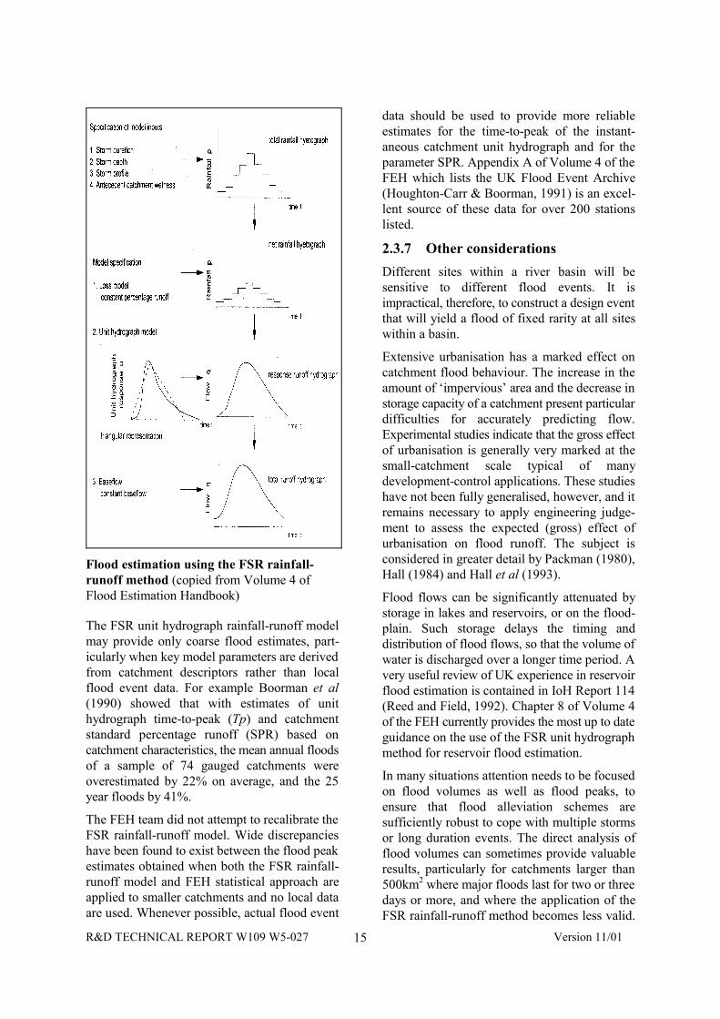
If the complete design flood hydrograph isrequired for a study catchment, then this is mostoften calculated using the FSR rainfall-runoffmodel. The figure opposite illustrates the mainsteps in the FSR unit hydrograph rainfall-runoffmethod. In summary, a design storm rainfallprofile is converted to a flood hydrograph usinga deterministic unit hydrograph and losses model.The main steps in the approach are:
• construct a total rainfall hyetograph for thedesign event;
• assess the proportion of rainfall whichcontributes directly to the flow in the river(constant percentage runoff);
• determine the catchment response toeffective rainfall (NB the unit hydrographshape is dictated by the time-to-peak); and
• calculate the quantity of flow in the riverprior to the event (baseflow).
Volume 4 of the FEH provides a comprehensivetechnical rewrite of the FSR unit hydrographrainfall-runoff method incorporating thenumerous enhancements contained in 18 FloodStudies Supplementary Reports and otherrelevant research published in the Institute ofHydrology (IH) Report series, various technicaljournals and conference proceedings. Whilst thebasic unit hydrograph rainfall-runoff method-ology is not greatly altered from these earlierpublications, some of the model parameterestimation equations have been updated in theFEH. Tables B.1 to B.3 of Volume 4 of the FEHsummarise the various changes to the modelparameter estimation equations and provide thedetails for the equations currently recommended.
R&D TECHNICAL REPORT W109 W5-027 Version 11/0115
Flood estimation using the FSR rainfall-runoff method (copied from Volume 4 ofFlood Estimation Handbook)
The FSR unit hydrograph rainfall-runoff modelmay provide only coarse flood estimates, part-icularly when key model parameters are derivedfrom catchment descriptors rather than localflood event data. For example Boorman et al(1990) showed that with estimates of unithydrograph time-to-peak (Tp) and catchmentstandard percentage runoff (SPR) based oncatchment characteristics, the mean annual floodsof a sample of 74 gauged catchments wereoverestimated by 22% on average, and the 25year floods by 41%.
The FEH team did not attempt to recalibrate theFSR rainfall-runoff model. Wide discrepancieshave been found to exist between the flood peakestimates obtained when both the FSR rainfall-runoff model and FEH statistical approach areapplied to smaller catchments and no local dataare used. Whenever possible, actual flood event
data should be used to provide more reliableestimates for the time-to-peak of the instant-aneous catchment unit hydrograph and for theparameter SPR. Appendix A of Volume 4 of theFEH which lists the UK Flood Event Archive(Houghton-Carr & Boorman, 1991) is an excel-lent source of these data for over 200 stationslisted.
2.3.7 Other considerations
Different sites within a river basin will besensitive to different flood events. It isimpractical, therefore, to construct a design eventthat will yield a flood of fixed rarity at all siteswithin a basin.
Extensive urbanisation has a marked effect oncatchment flood behaviour. The increase in theamount of ‘impervious’ area and the decrease instorage capacity of a catchment present particulardifficulties for accurately predicting flow.Experimental studies indicate that the gross effectof urbanisation is generally very marked at thesmall-catchment scale typical of manydevelopment-control applications. These studieshave not been fully generalised, however, and itremains necessary to apply engineering judge-ment to assess the expected (gross) effect ofurbanisation on flood runoff. The subject isconsidered in greater detail by Packman (1980),Hall (1984) and Hall et al (1993).
Flood flows can be significantly attenuated bystorage in lakes and reservoirs, or on the flood-plain. Such storage delays the timing anddistribution of flood flows, so that the volume ofwater is discharged over a longer time period. Avery useful review of UK experience in reservoirflood estimation is contained in IoH Report 114(Reed and Field, 1992). Chapter 8 of Volume 4of the FEH currently provides the most up to dateguidance on the use of the FSR unit hydrographmethod for reservoir flood estimation.
In many situations attention needs to be focusedon flood volumes as well as flood peaks, toensure that flood alleviation schemes aresufficiently robust to cope with multiple stormsor long duration events. The direct analysis offlood volumes can sometimes provide valuableresults, particularly for catchments larger than500km2 where major floods last for two or threedays or more, and where the application of theFSR rainfall-runoff method becomes less valid.

R&D TECHNICAL REPORT W109 W5-027 Version 11/0116
Archer et al (2000) provide one approach to theanalysis of flood volumes.
2.3.8 FEH guidelines
The Environment Agency is committed to theimplementation of FEH methods where suitableand has issued guidelines (Spencer and Walsh,2000) to assist Agency staff and its consultants toapply FEH correctly, including the systematicrecording of the methods and data used.
Flood frequency estimates by whatever methodare subject to change as methodologies evolveand as additional data become available. It isessential that engineers/hydrologists provide anaudit trail of how they arrived at their finaldesign flood estimate.
R&D TECHNICAL REPORT W109 W5-027 Version 11/0117
2.4 References
Topic Reference
Basic hydrology 6, 17, 18, 19, 23, 24,25, 26, 27
Estimation of meanflow
4, 5, 6, 13, 14, 15,17, 18, 19, 23, 24
Flood estimation1, 2, 3, 4, 7, 8, 9, 10,11, 12, 13, 14, 15,16, 17, 20, 21, 22, 25
1. Archer, D et al (2000) The synthesis ofdesign flood hydrograph, CIWEM/ICEWater Environment 2000: ‘Flood Warningand Management’, ICE, London
2. Babtie Group (2000) Clarification on the useof FEH and FSR design rainfalls,http://www.defra.gov.uk/environment/rs/01/index.htm
3. Boorman, D B et al (1990) A review ofdesign flood estimation using the FSRrainfall-runoff method, Institute ofHydrology Report Nº111, IoH Wallingford
4. Boorman, D B et al (1995) Hydrology of soiltypes: a hydrological classification of thesoils of the United Kingdom, Institute ofHydrology Report Nº 126, IoH Wallingford
5. Gustard, A et al (1992) Low flow estimationin the United Kingdom, Institute ofHydrology Report Nº 108, IoH Wallingford
6. British Hydrological Society (1994) Paperspresented at National meeting on FlowNaturalisation Using Hydrological Modelsheld at Institution of Civil Engineers, 17March, 1994
7. Packman, J C (1980) The effects ofurbanisation and flood magnitude andfrequency, Institute of Hydrology Report Nº63, IoH Wallingford
8. Hall, M J (1984) Urban hydrology, Elsevier;London
9. Hall, M J et al (1993) The design of floodstorage reservoirs, CIRIA Report RP393
10. Institute of Hydrology (1983) Somesuggestions for the use of local data in floodestimation Flood Studies SupplementaryReport Nº 13, IoH Wallingford
11.Houghton-Carr, H A and Boorman, D B(1991) A national archive of flood event datafor the UK, BHS 3rd National HydrologySymposium at Southampton
12. Institute of Hydrology (1996) Micro-FSR(version 2.2) Operation manual, IoHWallingford
13. Institute of Hydrology and British GeologicalSurvey (1988) Hydrometric register andstatistics 1981–5, IoH Wallingford
14. Institute of Hydrology and British GeologicalSurvey (1993) Hydrometric register andstatistics 1986–90, IoH Wallingford
15. Institute of Hydrology and British GeologicalSurvey (1998) Hydrometric register andstatistics 1991–95, IoH Wallingford
16. Laurenson, M and Mein, R G (1988) RORBVersion 4 Runoff routing program usermanual, Department of Civil Engineering,Monash University
17. Meteorological Office (1977) Maps ofaverage annual rainfall in Britain for theinternational standard period 1941-70,Meteorological Office
18. Meteorological Office (1981) The Meteorol-ogical Office rainfall and evaporationcalculation system – MORECS HydrologicalMemorandum 45, Meteorological Office
19. Ministry of Agriculture, Fisheries and Food(1976) Climate and drainage TechnicalBulletin 34, MAFF, London
20. Ministry of Agriculture, Fisheries and Food(1999) Flood Estimation Handbook Fivevolume report, MAFF, London
21. Natural Environment Research Council(1975) Flood Studies Report NERC, London.
22. Reed, D W and Field, E K (1992) ReservoirFlood estimation: another look, Institute ofHydrology Report Nº 114, IoH Wallingford
23. Searcy, S (1959) Flow-duration curves, USGeological Survey Water Supply Paper1542-A
24. Smith, L P (1967) Potential transpirationMinistry of Agriculture, Fisheries and FoodTechnical Bulletin Nº 16

R&D TECHNICAL REPORT W109 W5-027 Version 11/0118
25. Spencer, P and Walsh, P (2000) FloodEstimation Handbook: Guidelines Parts 1and 2, Environment Agency
26. Twort, A C et al (2000) Water supply, 5thedition, Edward Arnold, London
27. Wilson, E M Engineering hydrology 5thedition, Macmillan; Basingstoke
R&D TECHNICAL REPORT W109 W5-027 Version 11/0119
3. RIVER HYDRAULICS
3.1 Scope of the chapter
This chapter describes the hydraulic design andanalysis of natural and artificial channels and thestructures found in such channels. The object ofthis design is to determine how flow conditions(water depth, flow velocity and sedimentmovement in particular) are related to thedischarge and the physical characteristics of thechannel or structure.
3.2 Basic concepts
This section covers the basic concepts behindriver hydraulics, including the forces and energyinvolved, the laws of continuity and ‘control’.
3.2.1 Forces
The most important forces acting on flow in openchannels are gravity and inertia. The ratio ofthese forces is represented by the ‘Froudenumber’ (Fr) which identifies the flow as beingeither:
• subcritical (as in a deep, slow-moving river),for which Fr < 1; or
• supercritical (as in a steep chute), for whichFr > 1.
The identification of these two flow regimes is offundamental importance in open channel flowcomputations.
3.2.2 Continuity
The total mass of water entering a channel reachalso leaves that reach, in one form or another. Inmost practical problems, compressibility andtemperature effects (including evaporation) canbe ignored, so the total volume of water enteringa reach must also be the same as that leaving it.
3.2.3 Energy levelThe ‘total energy’, H, associated with a cross-section in an open channel can be expressed as:
gV
yZH2
2
α++= (Bernoulli’s equation)
where Z is the elevation of the bed relative to agiven datum, y is the water depth (so that Z + y isthe elevation of the water surface), ∀ is a
coefficient which depends on the velocitydistribution in the cross section, often taken as 1,and V is the average flow velocity.
The total energy along a channel can be plottedas a line, which will always be above the line ofthe water surface. This is the level to which thewater would rise in a pitot tube placed into theflow and facing directly into the flow at a pointwhere the velocity is representative.
3.2.4 Cr itical energy
For a given discharge and energy level, the flowin a channel can be either slow and deep(subcritical) or fast and shallow (supercritical).There is, however, a minimum energy level atwhich this discharge can be passed through aparticular cross-section. This is referred to as the‘critical’ energy, and the corresponding depth offlow as the critical depth. Under critical flowconditions, the Froude number, Fr = 1. Thismarks the transition between supercritical andsubcritical flow.
3.2.5 Control sections
In subcritical flow (Fr < 1) surface waves travelfaster than the flow, so any disturbance can bepropagated upstream. Conditions are thereforecontrolled by what happens downstream. Insupercritical flow (Fr > 1), waves are sweptdownstream, so that control is from upstream. Asa result, any structure or channel geometry whichcauses the flow to pass through critical depth actsas a ‘control section’, preventing the transmissionpast itself of any disturbance in the flow. Animportant feature of such controls is that thecritical depth (and hence the energy levelupstream) is defined solely by the discharge andthe channel cross section. This enables a controlsection to be used as the starting point for thecomputation of flow profiles.
Common critical-depth control sections includeweirs, flumes and drops in bed level. Otherfeatures, such as sluice gates, can also act ascontrol sections. Control sections only operate ashydraulic controls, however, for as long as theyremain ‘undrowned’: if they become ‘drowned’,the control moves further downstream. They are
R&D TECHNICAL REPORT W109 W5-027 Version 11/0120
also not the only type of control. Water levels inan estuary, for example, are controlled by thetide, while uniform flow at ‘normal depth’ (seebelow) can be a convenient control for comput-ational purposes.
3.2.6 Hydraulic jump
The transition from supercritical to subcriticalflow is referred to as a ‘hydraulic jump’. Thecharacteristics of a hydraulic jump (location,length and stability of position) depend on anumber of factors, including the Froude numberof the upstream flow and the tailwater levelprovided by the downstream control. Thesecharacteristics can be determined by consideringchanges in momentum. Hydraulic jumps aregenerally highly turbulent and dissipate consid-erable energy. As a result, they are likely to causeconsiderable damage if they take place inunprotected channels, particularly if the materialin the bed and banks is erodible.
3.2.7 Energy losses
Any flow along a channel is resisted by shearforces, or friction, acting on the wetted perimeter,and by the turbulence generated by irregularities,changes in size and cross-section and otherobstructions in the channel. Overcoming thisflow resistance results in a progressive loss ofenergy along the channel. Various formulae fordetermining this loss of energy have beendeveloped, the most common being the Manningequation, which incorporates an experimentallyderived roughness factor (Manning’s ‘n’) thatcan be related to the channel’s physical char-acteristics. Manning’s ‘n’ is generally used as a‘lumped parameter’, taking account of the effectsof variations in channel cross section, as well asthe surface texture. The Colebrook-White equat-ion can also be used, but is perhaps more suitedto lined channels with uniform cross-sectionsthan to natural channels.
3.2.8 Uniform and non-uniform flow
Uniform flow occurs in a channel with a constantcross-section when the gravity forces just balancethe resistance forces. Under these conditions, theenergy lost along a reach is the same as the fall inbed level, with the result that the depth, cross-sectional area and velocity of the flow areconstant and the energy line, water surface andbed are all parallel. True uniform flow rarely
occurs in natural channels, due to irregularity ofcross-section, and does not always occur inartificial channels, due to the presence ofcontrols. The concept is important, however, asit defines a depth/discharge relationship andhence the state to which the flow tends toconverge in a long uniform channel when noother controls are present. Uniform flow cantherefore be considered in itself as a control.
In steady non-uniform flow the discharge isconstant with time, but the depth varies along thechannel. If the depth varies gradually, asgenerally occurs some distance from a controlstructure, the pressure distribution over thechannel section can be taken as hydrostatic andthe water surface profile can be calculated fromthe control to the point where flow conditions areapproximately uniform. This ‘backwateranalysis’ can be done by hand, dividing thechannel into sections and using an iterative step-by-step method to carry the computation fromone section to the next. When doing this it isimportant to proceed from a control whereconditions are known in an upstream direction ifthe flow is subcritical and downstream if the flowis supercritical. The calculation is tedious,however, and many computer software packagesare available to carry out such analyses. Whenusing any package it is important to appreciatethe assumptions on which it is based and theresulting limits of applicability: some packagesare not good at representing particular hydraulicfeatures such as bridges or transitions.
If the flow depth varies rapidly along thechannel, the pressure distribution can no longerbe assumed to be hydrostatic. This complicatesthe analysis, with the result that there is nogeneral solution. Individual solutions to specificproblems are available, however, generally basedon a theoretical approach supported byexperimental results.
3.2.9 Steady and transient flow
The above description assumes steady flowconditions, implying a constant or near-constantdischarge (with time) along the channel. If thedischarge varies rapidly, as can happen duringthe passage of a flood or during operation ofgates, for example, ‘transient’ flow conditionsoccur. The analysis of these conditions iscomplex, needing to take into account such
R&D TECHNICAL REPORT W109 W5-027 Version 11/0121
matters as the transfer of water from the mainchannel to storage areas and possibly dynamiceffects. Advice from a hydraulic specialist shouldtherefore be obtained.
3.3 Hydraulics of r ivers andchannels
There are, in effect, two problems to beaddressed in the hydraulic design of natural andartificial channels. In existing channels theproblem is to determine the discharge capacityand hence what water levels will occur withdifferent flows. In new channels the problem is todetermine the cross-section required to pass agiven flow without the water rising to unaccept-able levels.
In both cases, the overall approach is similar. Thefirst step is to identify the control sections andlikely flow régime (subcritical or supercritical)under the full range of conditions that will beencountered. It is important to note that controlmay move from one place to another as the flowchanges and control sections become drownedout.
In most UK rivers, bed slopes are such that theflow is generally subcritical. Some rivers, part-icularly in hilly or steeply sloping areas, mayhave supercritical sections, separated by tranquilpools under low-flow conditions. During floods,the pools can be drowned out, so that the wholeflow is nominally supercritical.
3.3.1 Flow resistance
The main difficulty with hydraulic calculationsfor channels is determining the appropriateroughness factor (Manning’s ‘n’) to represent theresistance to flow that will occur over the fullrange of discharges. If the flow remains withinthe channel (in-bank), factors affecting Man-ning’s ‘n’ include:
• the bed and bank material;
• vegetation, in the channel and on the bank;
• variations in cross-section, size and shape ofchannel;
• the frequency and sharpness of bends;
• silting, scouring and bed sediment forms;
• the degree of obstruction (bridge piers, logjams etc); and
• stage and discharge.
Seasonal variations can occur due to vegetationgrowth and die-back, while maintenance pro-cedures can have a major impact if they involvesignificant dredging or weed-cutting. Guidanceon the value of Manning’s ‘n’ is available froma number of sources, with Chow (1959)providing a useful set of photographs. The choiceof ‘n’ value is important as flow velocity andhence discharge, is directly proportionate to ‘n’value.
The situation is considerably more complex if theflow is out-of-bank because of interactionbetween the in-channel and over-bank parts ofthe flow (noting that out-of-bank flow can occurin an embanked river if the floodbanks are setback from the bank of the normal channel). Thisis particularly so if the channel meanderssignificantly, since at places the over-bank flowmay be directed across the in-channel flow. Theeffective resistance to flow, and hence theconveyance/water level relationship, is verydifficult to determine in such cases and it isadvisable to seek specialist advice.
3.3.2 Sediment movement
Sediment can be transported in open channelflow either as ‘bedload’, which remains largely incontact with the bed and is carried forward bysliding or hopping, or as ‘suspended load’, whichis maintained in suspension by turbulence forconsiderable periods of time and moves withpractically the same velocity as the water. Someof the suspended load (the larger material) fallsback to the bed at intervals, but very fine materialis carried as ‘washload’ and is transportedwithout intermittent deposition.
The size of the material transported in each modedepends on the flow velocity and the grading anderodibility of material on the bed and broughtdown from upstream. A large number of methodsfor predicting sediment movement have beendeveloped (see, for example, Gomez and Church,1989 and Fisher, 1995) but care is needed intheir application. Some methods, such as thoseby Meyer-Peter and Muller, Bagnold andEinstein, cover only bedload, so are onlyappropriate where the mobile bed material iscoarse, such as gravel and cobbles. Otherformulae, of which the best known are theAckers and White and the Engelund and Hanson
R&D TECHNICAL REPORT W109 W5-027 Version 11/0122
equations, cover the total sediment load, soshould be used where there is significantsuspended sediment transport. Formulae coveringonly the suspended load are generallyinappropriate for sands, as some of the sandgenerally travels as bedload. Methods of Arora,Raju and Garde and by Westrich and Juraschekare available for estimating silt washload.
Flow over a bed of widely graded material canresult in the finer fraction being removed, leavingthe surface ‘armoured’ with coarser materialwhich is stable at that flow. If the flow sub-sequently increases significantly, this coarsematerial may become unstable and move, leavingthe bed unprotected and resulting in very rapiderosion.
The movement of bedload in particular isintimately connected with the development andmovement of bed features such as ripples anddunes in sand beds and riffles and runs in gravelbeds. These features, which are transient anddepend inter alia on the size of the bed materialand the velocity and depth of the flow, can havea major impact on the effective roughness of thechannel.
In all unlined channels, natural and artificial, thelong-term rate of sediment transport depends ona wide range of factors, including the timedistribution of flows, the slope and nature of thechannel and the characteristics of the catchment.These matters are discussed in Chapter 1.
3.4 Hydraulics of r iver structures
As discussed earlier, the flow at structuresgenerally varies rapidly (with respect to location),with the result that only in special cases can apurely theoretical result be obtained. Mostsolutions are therefore based on a theoreticalapproach supported by experimental results.Typical problems for which results are availableinclude:
• flow over weirs and spillways;
• flow through constrictions and expansions,including past bridge piers;
• discharge through and over gates;
• flow through culverts and so-called ‘invertedsiphons’;
• the hydraulic jump and energy dissipation;
• losses at bends; and
• the effects of steps, baffles and drops.
As always, it is important when applying theseresults to appreciate the range of conditions forwhich they apply. For particularly complex orunusual structures there may be no resultsavailable, in which case model testing may benecessary. Specialist advice should always beobtained in these circumstances.
3.5 Hydraulics of other features
The hydraulic analysis of environmentally sens-itive features, such as meanders, bays, pools,riffle-pool sequences and fish spawning ornursery areas can generally be undertaken usingthe approaches described above. For somefeatures, it may be necessary to ensure that theflow depth does not fall below a certain value orthat the velocity lies within a certain range. Thiscan often be achieved, since such requirementsare generally established on the basis of naturallyoccurring conditions, but may not always bepossible. If it is not, the advisability of imposingsuch a feature on the channel needs carefulconsideration.
The hydraulics of flow at river confluences,bifurcations and along parallel channels (aroundislands, for example) can be complex, but againare generally solvable applying the approachesoutlined above. The main difficulty is oftendetermining the division of flow that will occurwhen a channel bifurcates. Frequently this canonly be determined by trial and error, balancingthe head losses that will occur along the channelsso that the energy levels in each are the same atthe beginning and end of the section. Thedivision may, of course, vary as the total flowvaries.
R&D TECHNICAL REPORT W109 W5-027 Version 11/0123
3.6 References
Topic ReferencesBasic concepts 3, 5, 6, 9, 15Hydraulics of riversand channels
1, 10, 11, 12, 13, 16,17, 19
Hydraulics of riverstructures 2, 5, 18
Sedimentation 7, 8, 15, 19, 20Hydraulics of otherfeatures 4, 14, 21
1. Ackers, P (1992) Hydraulic design of two-stage channels, Proceedings Institution ofCivil Engineers, Water, Maritime and EnergyVol 130 Issue 2
2. Ackers, P et al (1978) Weirs and flumes forflow measurement, J Wiley & Sons Ltd;Chichester
3. Brater, E F, King, H W, Lindell, J E andWei, C Y (1996) Handbook of hydraulics(for the solution of hydraulic engineeringproblems), 7th edition, McGraw Hill, NewYork
4. Brookes, A & Shields F D (1996) Riverchannel restoration – guiding principles forsustainable projects, J Wiley & Sons Ltd;Chichester
5. Chow, V T (1959) Open channel hydraulics,McGraw-Hill Book Company, New York
6. Davis, C V and Sorenson, K E (1989)Handbook of applied hydraulics, 3rd edition,McGraw-Hill
7. Fisher, K R (1995) Manual of sedimenttransport in rivers, HR Wallingford
8. Gomez, B and Church, M (1989) Anassessment of bedload sediment transportformulae for gravel bed rivers, WaterResources Research, Vol 25, Nº 6, pp1161–1186
9. Henderson, F M (1966) Open channel flowMacmillan, New York
10. Hicks & Mason (1992) Roughnesscharacteristics of New Zealand rivers, WaterResources Survey; DSIR Marine andFreshwater
11. Hydraulics Research (1988) Internationalconference on river régime, White, W R(Ed.) J Wiley & Sons Ltd, Chichester
12. Hydraulics Research (1990) Internationalconference on river flood hydraulics, White,W R (Ed.) J Wiley & Sons Ltd; Chichester
13. Hydraulics Research (1992) Assessment offlows in meandering compound channels,Report EX 2606, HR Wallingford
14. HR Wallingford (in press) Handbook forassessment of hydraulic performance ofenvironmental channels, HR Wallingford
15. Hydraulics Research (1990) Sedimenttransport: The Ackers and White theoryrevised, SR 237 HR Wallingford
16. Izbash, S V and Khaldre, Kh Yu (1970)Hydraulics of river channel closure,Butterworths, London
17. Lambert, M F and Myers, W R (1998)Estimating the discharge capacity in straightcompound channels, Proceedings Institutionof Civil Engineers, Water, Maritime andEnergy Vol 130 Issue 2
18. Miller, D S (Ed) (1994) Dischargecharacteristics, IAHR Hydraulic StructuresDesign Manual 8, Balkema, Rotterdam
19. Raudkivi, A J (1976) Loose boundaryhydraulics, 2nd edition, Pergamon Press
20. Thorne, C R et al (1987) Sediment transportin gravel bed rivers J Wiley & Sons Ltd;Chichester
21. US Army Corps of Engineering (1970)Hydraulic design of flood control channelsEngineering Manual EM1110-201601

R&D TECHNICAL REPORT W109 W5-027 Version 11/0124
R&D TECHNICAL REPORT W109 W5-027 Version 11/0125
4. TIDE AND SURGE LEVEL PREDICTIONS
4.1 Scope of the chapter
This chapter describes the sources of availabledata and the methods of calculating design waterlevels at the downstream limit of the fluvialsystem, which are influenced by factors otherthan fluvial flow. These include both predictable,regularly occurring events, such as tidalvariation, and random events, such as meteor-ological surges. Superimposed upon these short-term variations are longer-term variations, suchas sea level rise and tectonic changes, which alsohave to be considered.
Many of the methods described here are commonto both fluvial and coastal systems. Flooddefences within the downstream reaches of afluvial system, however, also have the furtherdimension of freshwater flow influencing thedesign level.
Downstream water levels can significantly affectthe discharge capability of a river and henceupstream flood water levels. It is thereforeimportant to understand fully the influence of oneon the other.
River flow may be considered as a randomvariable, depending upon random rainfall eventsand the catchment characteristics. Tidal variation,on the other hand, is predictable and isindependent of the factors affecting river flow.Meteorological surges are dependent upon theweather, which may or may not, depending uponlocality, be related to the factors affecting riverflow. The only way to relate all these variables isthrough the use of probability analysis andstatistics.
The level of effort required in determining therelationships between the different variables, forany particular project, depends upon the localityof the project, the degree of acceptable risk andan assessment of the sensitivity of design floodlevel to changes in any, or all, of the parameters.In most cases, the accuracy of any prediction willbe determined by the quality and quantity of dataavailable, and the time (and budget) within whichthe assessment needs to be carried out.
4.2 Basic concepts
Downstream water levels are composed mainlyof two superimposed parts:
• the tidal variation; and
• the meteorological surge.
Tides are produced by the gravitational inter-action of all heavenly bodies with the earth,although the main influences for tidal movementsare the moon and the sun. All the heavenlybodies, including the earth, move in regular,predictable orbits. Their influence upon eachother and therefore upon the earth is alsopredictable and can be estimated to a high degreeof accuracy for any time, either in the past or thefuture. The tide-producing forces have a repeat-ing cycle of approximately 18.6 years. The relat-ionship between astronomical force and the localtide for any particular place on the globe, how-ever, has to be determined by on-site measure-ments.
Surges are produced by the passage of high orlow-pressure weather systems, causing alowering (negative surge) or raising (positivesurge) of the water level respectively. The surgeis therefore the difference between measured andpredicted tide level. Meteorological surge issuperimposed upon the astronomical tide. Intheory, the surge peak can occur at any timewithin the tidal cycle, as the two are totallyindependent. This will be discussed further later.
In some cases, wind and wave ‘setup’ could alsobe relevant. Wind setup is a tilting of the watersurface due to the action of wind stress on thewater surface, resulting in a rise in water level atthe downwind end of a water body and a fall atthe upwind end. Wave setup is a rise in waterlevel near a sloping shore, due to the conversionof wave energy to potential energy.
4.3 Water level predictions
Water levels have been measured and recordedon a systematic basis, mainly at ports, around thecoast of the United Kingdom, for over 100 years.The data are held both locally at the port and
R&D TECHNICAL REPORT W109 W5-027 Version 11/0126
centrally at the Institute of OceanographicSciences (IOS).
The quality and therefore useable quantity of datafor any particular locality is highly variable, andreference therefore needs to be made to IOS atan early stage. Changes in measurement tech-nology have led to the establishment of a seriesof ‘A’ class stations, which produce high qualitycontinuous water level recordings, and otherlower class stations which produce either inter-mittent readings or less reliable data. All coastallocations around the UK can however be relatedwith sufficient accuracy for most projects to an‘A’ class station. Localities within estuaries andwithin the fluvial system cannot usually berelated with as much confidence.
If time permits, it is highly desirable to obtainmeasured water level data at the site, or sites, ofinterest for a period of preferably at least 28 days.If continuous recordings are not practicable, thenintermittent readings at hourly intervals cansuffice. For a small fee IOS will analyse thereadings and relate the site to the nearest ‘A’class station. The longer the period of record andthe closer the time interval between readings, themore accurate the relationship between the siteand the ‘A’ station is likely to be. The readingsshould be taken at times of low river flow;otherwise a longer period of record will berequired, together with records of river flow.
Tide Tables are published annually, in fourvolumes, by the Hydrographer of the Navy, for aseries of ‘standard ports’ around the world. Thesepredict the time and level of high and low watersand a series of tidal parameters, depending uponthe nature of the tide at that locality. Alsoincluded are factors to be added to or subtractedfrom the times and levels at the standard port todetermine the corresponding data for various‘secondary ports’.
The tides around the coast of the UK aresemidiurnal in nature; there are generally twohigh waters and two low waters each day, ofapproximately the same amplitude. Each tidalcycle lasts about 12.5 hours. The tides vary fromday to day on a ‘spring–neap’ cycle of about14.6 days. The ‘spring’ tides are of high amplit-ude, with low low-water levels and high high-water levels, whereas the ‘neap’ tides are of lowamplitude, with higher low-waters and lower
high-waters. Although the form of the tide isconstant around the UK, the range of the tide issignificantly different; varying from over 13m onspring tides off the Bristol Channel to 2.7m atPortland and 2.6m at Lerwick.
Offshore, the shape of the tide is approximatelysinusoidal, but as it approaches the shore it ismodified by shallow water effects as a longperiod wave. The distortion of the tidal curve ismost pronounced within estuaries, as it ismodified not only by the bed but also by thebanks. The ‘flood’ (incoming) tide generallybecomes shorter further up an estuary, with the‘ebb’ (outgoing) tide being lengthened. Theextreme case of this is the ‘bore’ formed duringhigh spring tides in the Severn Estuary.
Surges are the variation between measured andpredicted (astronomical) tidal levels. Minorvariations occur most days, but the levels aregenerally within 0.2m of the predictions. Largervariations may be caused by a prolonged periodof high pressure, causing a reduced tidal level (ornegative surge), which can be of concern for shipnavigation. For flood defences positive surges areof concern. These are generated by the passage oflow pressure weather systems.
The effect of these weather systems varies aroundthe coast of the UK. Maximum surges occur inthe South East off the Thames Estuary, and arecaused by low pressure systems passing to thenorth of Scotland and then down the East Coast,forcing a mass of water into the southern NorthSea. The maximum surge with a return period of50 years at this location is about 3m.
Extreme low pressure weather systems occurpredominantly during the winter, so large pos-itive surges are also a function of the season, withsurges likely to affect flood defences occurringbetween November and February.
The shape of the surge is a function of localityand the speed and depth of the depression. Theycan vary from short, very intense events, whenwater levels are raised by 2 to 3m for a period ofonly a few hours, with the whole event overwithin 12 to 24 hours, to long duration lowintensity events, when the water level is raisedonly by 0.5 to 1m, but for a period of three tofour days. Either can be critical to the design ofa flood defence. The former is likely to be criticalcloser to the estuary mouth or on the coast,
R&D TECHNICAL REPORT W109 W5-027 Version 11/0127
whereas the latter could influence water levels aconsiderable distance upstream.
Although, in theory, astronomical tides andmeteorological surges are independent, beingcaused by forces which are unrelated, there isevidence that surge peaks do not coincide withthe time of highest high water, which wouldoften be the worst design condition. The mostlikely reason is that, because the tide, and hencethe tide plus surge, acts like a long period wave,it is influenced by shallow water effects, partic-ularly shoaling and bottom friction. These tend toexaggerate surges occurring at lower water levelsand to suppress surges at higher water levels. Itis, however, generally good practice to considersurges and tidal level as totally independent, andto design for an adverse combination.
There is strong evidence that sea levels are risingworldwide. At present, the rise is of the order of1–1.5 mm/year around the UK, although thereare concerns that this may increase due to ‘globalwarming’. Opinion is divided regarding the likelyrate of rise. Guidelines have been issued byMAFF (now DEFRA) for various regions of thecountry.
During the last Ice Age, the north of the BritishIsles was covered by an ice sheet down to abouta line between the Wash and the Bristol Channel.The land beneath the ice sheet was depressed andthe south of England tilted upwards. Since theretreat of the ice, the land has been recovering,with the north rising and the south falling relativeto the sea.
The combined effect of the geodetic change andthe sea level rise is for the sea level in the southeast of England to be rising relative to the land atsomewhere in the region of 4–6 mm/year, where-as in the north of Scotland the sea is fallingrelative to the land by a similar amount.
4.4 Joint probability (tidal level andfluvial flow)
The probability of a particular sea level due to acombination of tide and surge can be computedby considering the two events as mutually indep-endent. The result can then be expressed as a‘return period’, which is the average time inyears which elapses between events of equal, orworse, intensity. In terms of probability, the
chance of, for example, a 50-year return periodevent occurring in any one year, is 2%.
With rising, or falling, sea levels, as discussedabove, the return period does not remain constantwhen designing for a life of say 50 years to 100years. Depending upon the relationship betweendesign water level and return period, a sea levelchange of only 0.2m during the design life (forexample, 50 years at 4 mm/year) can alter the‘standard of service’ from the original 100-yearreturn period upon scheme completion, toperhaps a 20-year return period or less by the endof the scheme’s design life. Looked at anotherway, to achieve a standard of service equivalentto a 100-year return period at the end of a 50-yeardesign life, may require an initial design to areturn period of 500 years or even longer.
Although there is no direct correlation betweenmeteorological surges and rainfall, both arecaused by low pressure weather systems, so thereis likely to be some degree of correlation. Surgesare the direct result of low pressure, whereasfluvial flow depends upon rainfall runoff and thetime delays inherent in the river basin, whichmay delay the peak fluvial flow to long after thepeak of the surge. Each situation therefore needsto be assessed individually.
At the mouth of an estuary, tidal effects normallydominate for the design of flood defences,whereas in the upstream reaches fluvial flowbecomes more important. In between, the twoeffects interact. The best method of predictingflood levels of varying return period along a riveror estuary is to analyse data from a series oflocations with long term water level records.Without those, the next best solution is adynamic mathematical model of the system,proven against a series of known events. Themodel needs to be run for a number of differentcombinations of fluvial flow and tidal conditionsof known return periods.

R&D TECHNICAL REPORT W109 W5-027 Version 11/0128
4.5 References
Topic ReferencesBasic concepts 1, 3, 6, 8, 9, 11, 12,
13, 14, 17, 18, 19,20, 23, 24, 25, 26,27, 28, 30, 31, 32,33, 34, 37, 38, 39,40, 41, 42, 43, 45,46, 48
Water levelpredictions
2, 4, 5, 7, 9, 10, 12,15, 16, 22, 29, 35,39, 47
Joint probability 21, 29, 32, 36, 44
1. Alcock, G (1989) Research on tides, surgesand waves in Coastal Management:Proceedings of a conference organised by theMaritime Engineering Board of theInstitution of Civil Engineers, Bournemouth,9-11 May 1989, Thomas Telford, London
2. Amin, M (1988) Surge prediction at Barrow-in-Furness, Proudman OceanographicLaboratory; Birkenhead
3 Arnell, N W et al (1994) The implications ofclimate change for the National RiversAuthority, Institute of Hydrology for theNational Rivers Authority, R&D Report 12
4. Boorman, L A et al (1989) Climatic change,rising sea level and the British coast, NaturalEnvironment Research Council ITEPublication 1, HMSO, London
5. Bray, M J (1992) Sea level rise and globalwarming: Scenarios, physical impacts andpolicies, University of Portsmouth,Department of Geography for the StandingConference on Problems Associated with theCoastline (SCOPAC)
6. Cooper, A J and Dearnaley, M, Flow (1996)Guidelines for the use of computationalmodels in coastal and estuarial studies, HRWallingford Sediment Transport ModelsSupplementary Report Nº 456
7. Co-tidal and Co-range lines (1971) AdmiraltyChart Nº 5058, British Isles and AdjacentWaters, Hydrographer of the Navy
8. Department of the Environment andMeteorological Office (1990) Global climate
change, Department of the Environment andthe Meteorological Office
9. Dixon, M J and Tawn, J A (1994) Extremesea levels at the UK A-class sites: site by siteanalysis, Proudman OceanographicLaboratory, Internal Document 65
10. Dixon, M J and Tawn, J A (1995) Estimatesof extreme sea conditions; extreme sea levelsat the UK A-class sites: optimal site by siteanalyses and spatial analyses for the EastCoast, Proudman Oceanographic Laboratory,Internal Document 72
11. Dixon, M J and Tawn, J A (1997) Extremesea levels around the UK coastline Paper B3,MAFF conference of River and CoastalEngineers; Keele University
12. Dixon, M J and Tawn, J A (1997) Spatialanalyses for the UK coast, ProudmanOceanographic Laboratory, InternalDocument 112
13. Doornkamp, J C (Ed) (1989) The greenhouseeffect and rising sea levels in the UK,including a selection of papers presented atthe MAFF Conference for River and CoastalEngineers, Loughborough, 11-13 July 1989,M1 Press, Nottingham
14. El-Jabi, N et al (1992) Stage dischargerelationships in tidal rivers, ASCE Journal ofWaterway, Port, Coastal and OceanEngineering, Vol 118 Nº 2, March/April1992, pp 166-174
15. Environment Agency (1999) 1:10,000Indicative flood plain maps for England andWales, Environment Agency
16. Flather, R A (1982) The west coast surgeprediction experiment 1981-82, Institute ofOceanographic Sciences, Godalming
17. Graff, J (1981) An investigation of thefrequency distribution of annual sea levelmaxima at ports around Great Britain,Academic Press, London
18. Graff, J et al (1977) The analysis of annualextreme tidal levels at certain ports on thesouth coast of England, Parts 1 and 2,Institution of Oceanographic Sciences,Godalming
R&D TECHNICAL REPORT W109 W5-027 Version 11/0129
19. Havno, K (1996) Flood mapping and riskassessment based on joint probabilityextreme value analysis, Proceedings 31stMAFF Conference for River and CoastalEngineers, pp 3.4.1–3.4.12
20. Hedges, T and Reis, M T (1999) Riskassessment of coastal defences, Proceedings34th MAFF Conference River and CoastalEngineers
21. HR Wallingford/Lancaster University(1998), The joint probability of waves andwater levels – JOINSEA – a rigorous butpractical new approach, HR WallingfordReport SR 537
22. Hydrographer of the Navy (1999) AdmiraltyTide Tables 2001, Vol 1: United Kingdomand Ireland
23. Institution of Civil Engineers (1953)Conference on the North Sea floods of 31January to 1 February 1953, Institution ofCivil Engineers, London, December 1953
24. Institution of Civil Engineers (1996) Landdrainage and flood defence responsibilities,3rd edition, Thomas Telford, London
25. Intergovernmental Panel on Climate Change(1990) Climate change: the IPCC scientificassessment, Cambridge University Press,Cambridge
26. Irish Sea Forum (1993) Seminar on risingsea level and coastal defences, UlsterMuseum, Belfast, 22 April 1993, Irish SeaForum, Liverpool
27. Lennon, G W (1965) Storm surges on thewest coast of the British Isles in 1965,Institute of Coastal Oceanography and Tides,Internal Note Nº 29
28. Macmillan, D H (1966) Tides, C R BooksLtd, London
29. Mantz, P A & Wakeling, H L (1979)Forecasting flood levels for joint events ofrainfall and tidal surge flooding usingextreme value statistics, Proceedings ICE,Part 2, Vol 67, pp 31-50
30. Meadowcroft, I (1996) Risk assessment forcoastal and tidal defences, Proceedings 31stMAFF Conference for River and CoastalEngineers, pp 3.3.1–3.3.12
31. Ministry of Agriculture, Fisheries and Food(1999) Flood and coastal defence projectappraisal guidance, FCDPAG3, MAFF,London
32. Ministry of Agriculture, Fisheries and Food(1993) Strategy for flood and coastal defencein England and Wales, P61471, 39pp,MAFF, London
33. Morris, D G and Flavin, R W (1996) Floodrisk map for England and Wales, Institute ofHydrology Report Nº 130
34. National Rivers Authority (1993)Methodology for collating tidal water leveldata, Note 197, National Rivers Authority,Bristol
35. Ovadia, D C (1980) A regression model forthe statistical prediction of extreme sea levelsat Liverpool, Institute of OceanographicSciences, Report Nº 102
36. Owen, M, Hawkes, P, Tawn, J, and Bortot, P,(1997) The joint probability of waves andwater levels: a rigorous but practicalapproach, Proceedings 32nd MAFFConference of River and Coastal Engineers
37. Pugh, D T (1987) Tides, surges and meansea level: a handbook for engineers andscientists J Wiley & Sons Ltd, Chichester
38. Pugh, D T (1990) Is there a sea levelproblem? Proceedings ICE, Part 1, Vol 88,June 1990, pp347-366
39. Roberts, L E J & Kay, R C (Eds) (1990) Theeffects of sea level rise on the UK coast,Environmental Risk Assessment Unit,University of East Anglia
40. Samuels, P (1996) The effects of climatechange on flood and coastal defence in theUK, Proceedings 31st MAFF Conference forRiver and Coastal Engineers, pp 2.2.1–2.2.10
41. Smith, J A (1994) The operational stormsurge model data archive, ProudmanOceanographic Laboratory; Birkenhead
42. Taylor, D R (1995) An analysis of sea levelchange in the Severn Estuary, University ofBristol
43. The United Kingdom Climate ChangeReview Group (1991) The potential effects of
R&D TECHNICAL REPORT W109 W5-027 Version 11/0130
climate change in the United Kingdom, TheStationery Office, London
44. Thompson, G (1995) The use of jointprobability analysis for the design of flooddefences, Proceedings 30th MAFFConference for River and Coastal Engineers,pp 3.2.1–3.2.12
45. University of Liverpool (1992) The Irish Sea:global warming and climatic change,Seminar held on 26 April 1992, University ofLiverpool, Liverpool University Press
46. Warrick, et al (1993) Climate and sea levelchange: observations, projections andimplications, International Workshop onclimatic change, sea level, severe tropicalstorms and associated impacts held inSeptember 1987, Cambridge UniversityPress, Cambridge
47. Westerink, J J et al (1992) Tide and stormsurge predictions using finite element model,ASCE Journal of Hydraulic Engineering, Vol118, Nº 10, October 1992, pp 1373-1390
48. Woodworth, P L (1999) Trends in BritishIsles mean sea level, CCMS ProudmanOceanographic Laboratory, Proceedings 34thMAFF Conference of River and CoastalEngineers

R&D TECHNICAL REPORT W109 W5-027 Version 11/0131
5. DATA COLLECTION
5.1 Scope of the Chapter
This chapter considers the type of data that maybe needed for a project and the problems thatmay encountered in its collection. Briefs for thecollection of such data should be written toreflect the specification requirements of theprojects.
5.2 Overall Approach
The following factors need to be taken intoaccount when planning a data collectionprogramme:-
• the availability, reliability and form ofexisting data;
• the accuracy and amount of the data requiredby the project;
• the cost of collecting the data; and
• the management, storage and use of the dataafter collection.
In general it is advisable to:-
• identify the need for data as early as possible;
• search for and use existing data whereverpossible;
• design data collection programmes in detail;
• assess data handling requirements andconsider the use of innovative handlingtechniques.
5.3 Data Sources
The Agency will often hold much of the baselinedata required for a project. Other organisationswill also hold useful information, however. Thetypes of data held by different organisations arelisted below.
Environment Agency
• rain gauge data
• river and tide levels
• river cross-sections and bank levels
• flooded area (section 105) plans
• observations by flood defence staff
• river flow data
• water quality data
• ecological data
• fisheries data
• sediment (including suspended sediment)data
Meteorological Office
• rain gauge data
• wind data
• evaporation data
Institute of Hydrology
• river flow data
• evaporation data
British Geological Survey
• geological maps
• geological memoirs
• borehole information
English Nature, RSPB, County Wildlife Trusts
• ecological data
• designated sites
• biological action plans
• amenity and recreation
Angling Clubs, MAFF, Sea Fisheries Committees
• fish species and stocks
• shell fish
R&D TECHNICAL REPORT W109 W5-027 Version 11/0132
Local Authorities, Countryside Commission
• aerial photography
• recreation and amenity
• nature conservation
• local heritage
Local Libraries, Historical Associations
• records of flooding
• historic land use
Ordnance Survey
• maps
• aerial photographs
National Monuments Archive
• aerial photographs (historic)
Water Companies
• abstractions and returns
• effluent discharges
• stormwater outfalls
Industrial Companies
• abstractions and returns
• effluent discharges
Port/Navigation Authorities
• bathymetry
• tidal records
• currents
• sediment movement and dredging
• ship sizes and constraints
• ship movements and pilotage
5.4 Data Management
Data management problems may include thesheer volume of the data, its format and consist-ency. Data management may be helped by:
• using standard data formats;
• storage of data in standard spreadsheets ordatabases, possibly linked to a GIS system;
• use of statistical checks on data consistencyand trends; and
• archiving of data in open locations for futureuse by others.
When storing data it is important to includeinformation about its source, date and scale ofcapture and reliability.
5.5 Topographic and Bathymetr icSurveys
Traditional or innovative methods, includingthose below, should be considered, as appropriateto the project:
• traditional land survey techniques;
• ‘total station’ techniques;
• aerial photographs and photogrammetry;
• echo sounding;
• global positioning systems (used on land orwater); and
• LIDAR (Laser Instrument Doppler AirborneReconnaissance).
The national framework for Section 105 FloodMapping has produced a number of standardsurvey and data formats. These represent bestpractice and should be considered for surveywork.
5.6 Flow and Water Level Surveys
Much of the data on discharges and water levelswill come from existing flow gauging stations.However, the accuracy and reliability of thesestations should always be checked, as should theapplicability of the data for the purpose intended.The measurements from gauging stations may beaffected by vandalism.
R&D TECHNICAL REPORT W109 W5-027 Version 11/0133
There are often problems in recording maximumflood levels properly, as they are beyond therange of the equipment, so reliance may have tobe placed on separate human observations. Therating relationships used to convert levels todischarges may also be unproven at the highestlevels.
In some cases, where there is an adequate ‘leadtime’ for a study, consideration may be given tothe installation of new gauges. Such data wouldprobably not be of sufficient duration for use inits own right, but may be useful for correlatingwith data at neighbouring stations with a longerrecord.
5.7 Water Quality Data
It should be remembered that significant localvariation of parameters may be found in the field.Parameters should always be compared with‘textbook’ values, and carefully reviewed, beforeassuming values outside the usual range.
5.8 Geomorphology and SedimentData
Surveys of river geomorphology are discussed inChapter 1. Sampling of bed sediments isrelatively easy to arrange but meaningfulinformation about sediments in motion is difficultto collect as much of the transport occurs onlyunder flood conditions.
5.9 Asset Condition Surveys
Preliminary condition surveys will provideinformation about the superficial appearance ofthe asset but cannot examine conditions belowground or (normally) below water, The need foradditional information should be consideredcarefully and it is recommended that, if there isany doubt, expert advice should be sought.Record drawings are invaluable but are notalways available for older structures.
5.10 Environmental BaselineInvestigations
Information for environmental baseline surveysshould be identified through consultations carriedout as part of the scoping process. Much of theinformation is generally available through theAgency or from external consultants. Sometimes
it will be necessary to commission more detailedsurveys.
5.11 Geotechnical Investigations
A sound understanding of local groundconditions is essential for good design. Siteinvestigations should be properly structured andplanned, with sufficient time allowed to carry outthe tests needed and prepare reports, as set out inBS 5930. It is recommended that specialistgeotechnical advice is obtained as set out inReference 8. For many projects this will requirethe appointment of a geotechnical adviser with aminimum of 8 years relevant post charterexperience.
R&D TECHNICAL REPORT W109 W5-027 Version 11/0134
5.12 References
Topic ReferencesBasic concepts 2, 3, 4, 5, 9Specialist advice 1, 6, 7, 8, 10
1. British Standard (1999) Code of practice forsite investigations BS 5930
2. Environment Agency (1997) Flood DefenceManagement Manual (implemented by theFlood Defence Management System)Environment Agency Pin Volume 29
3. Environment Agency (various) RegionalEnvironmental Databases
4. Environment Agency (1999) NationalStandard Contract and Specification forSurveying Services Environment Agency
5. McCrae, R U (1996) Quality Assurance forSurveying for the Environment Agency,R&D Project 679
6. National Rivers Authority (1995) AssetManagement Planning National RiversAuthority R&D Note 199
7. Seed, D J, Samuels, P G and Ramsbottom, DM (1978) Quality Assurance inComputational River Modelling, Institute ofHydrology Report SR 374, HR Wallingford
8. Site investigations in Construction Part 1‘Without site investigation ground is ahazard’. Thomas Telford 1993
9. White, W R, Forty, E J (1999) Open ChannelFlow Gauging Stations: Extension ofPermissible Flow Conditions, Department ofthe Environment, Transport and the Regions(DETR)
10. Environment Agency (1999), NationalStandard Contract and Specification forSurveying Practices, Volume 1 Best PracticeManual.
R&D TECHNICAL REPORT W109 W5-027 Version 11/0135
6. FLUVIAL MODELLING
6.1 Scope of the Chapter
This chapter covers the key factors involved inthe computational and physical modelling ofriver systems.
6.2 Basic Concepts and CommonConcerns
6.2.1 Types of model
Two types of model are available for modellingriver systems:
• computational models, for reach and basin-wide analysis; and
• physical models, for detailed analysis of localhydraulic features.
6.2.2 Uses and concerns
Computational models enables the engineer to:
• consider basin-wide impacts of fluvial works;
• examine a wide range of design options in ashort time; and
• achieve, in most cases, greater accuracy andconfidence in the results.
Increased use of computational modelling hasalso introduced a number of concerns for theproject manager, including:
• appreciating the simplifications andassumptions inherent in the methods;
• selecting the appropriate model to use for aproject;
• understanding the results and their accuracy;and
• management and budget control of modellingspecialists.
The use of physical modelling avoids some ofthese concerns, but adds others, including:
• understanding the physical scaling lawsgoverning the design and operation of themodel;
• limits imposed by the physical size of themodel and the scale available;
• the time taken for model construction andtesting; and
• the time needed for making revisions andrepeating testing.
6.2.3 Calibration and ver ification
The accuracy of a model is generally examinedthrough a process of calibration and verification.The model is first calibrated, using data recordedduring a number of events covering the range ofconditions for which it is to be operated. It is thenverified using data from other, independent,events to show how well the conditions predictedmatch those that occurred.
When examining calibration and verificationresults the limitations and uncertainties inherentin the way physical reality is represented in themodel must be recognised. Uncertainty in para-meters such as hydraulic roughness, the accuracyof flow and level measurements or estimates andthe variability of physical processes such assediment movement, may all contribute tomodelling inaccuracy.
6.3 Hydrologic Modelling
Hydrologic models include:
• statistical models, such as the methodspresented in the Flood EstimationHandbook; and
• river basin models, which vary greatly incomplexity, but all include a rainfall/runoffsimulator and flood routing along riverreaches.
Hydrologic models may be used to produceinflow hydrographs for a hydrodynamic model ofa river system. They may also be used inisolation, for example to assess the effect of flooddetention basins in a catchment.
R&D TECHNICAL REPORT W109 W5-027 Version 11/0136
6.4 River System Modelling
The primary types of computational models forriver systems are:
• ‘backwater’ models, used for modelling shortreaches of river, along which there is littleflow attenuation and flood storage; and
• fully dynamic models, used for modellinglarger and more complex river systems.
Such models are generally 1-D models, assumingdepth-averaged and width-averaged parametersacross a river section, or pseudo 1-D models,which allow a representation of out-of-bankfloodplain flow. Many models have facilities foradd-on modules to simulate parameters such aswater quality and sediment movement.
The correct and early choice of model type andsoftware is a vital part of effective fluvialmodelling. The choice of model must consider:
• the project aims;
• the required accuracy of the model;
• the software available to the project team;and
• the budget.
Early design of the model is also required todirect the data collection exercise properly. Thedesign must consider the above points, togetherwith:
• the geographical extent of the model;
• the ‘scale’ (cross-section spacing) of themodel and the law of diminishing returns interms of increased data density;
• the boundaries of the model, which may needto coincide with gauging stations, weirs, orother well defined fluvial features; and
• calibration and verification locations andaccuracy.
Data required for the model includes:
• topographic data for model definition;
• flow and level data for model calibration;and
• other parameters (e.g. water quality).
The modellers should be either consulted orresponsible for deciding on the locations for thecross sections.
The accuracy of data, even from gauging stations,should not be assumed. Data collection isconsidered in more detail in Chapter 5. Inflowhydrographs, usually determined from hydrol-ogical studies, are also needed for model designruns. In many cases, urban stormwater and sewerflows also need to be included.
Building, calibration and verification of a modelshould follow directly from good design and datacollection.
Model reporting must include assessment of themodel accuracy, perhaps in the form ofsensitivity analyses.
The national framework for Section 105 FloodMapping has produced a number of standardguidelines and record sheets for river modelling.These represent best practice and should beconsidered for all work.
6.5 Estuar ine System Modelling
Computational modelling of estuaries is generallysimilar to river modelling, but with the additionof a seaward boundary where the levels follow atidal curve. Estuarine modelling may be requiredto provide a realistic downstream boundarycondition for a fluvial model. In other cases thefluvial model may be extended into the estuary.Care must be exercised where an estuary is:
• wide, with significant flow variations acrossits width; or
• stratified, with significant stratification ofsaline and fluvial flows.
Additional model types are available forestuarine modelling, for simulation of the aboveconditions. These include 2-D models, eitherallowing horizontal or vertical variation ofparameters through a cross section, and full 3-Dmodels, allowing variation in both planes. Itshould be noted that such models are generallymore difficult and costly to build and calibrate,the data requirements being greater.
R&D TECHNICAL REPORT W109 W5-027 Version 11/0137
6.6 Management of Modelling
Close liaison between management andmodelling must be maintained, to integrateengineering, environmental and specialistmodelling disciplines, and to prevent themodelling from becoming an end - howeverinteresting - in itself.
Management concerns may be reduced by clearterms of reference, with early preparation of adetailed specification of the modelling tasks. Thisformalises the model objectives, design,software, calibration and verification, accuracyand reporting.
Cost estimates for modelling projects are oftenoptimistic, overlooking the potential delays andproblems with data, model or computer hardwarethat can occur. To some degree this may beinevitable in a competitive tenderingenvironment, so should be taken into account indrawing up briefs and reviewing tenders.
It should also be recognised that the investigatorynature of computational modelling will oftenresult in genuine difficulty in assessing time andcost budgets in advance.
Cost control may be improved by:
• detailed specification;
• ensuring the timely availability of all the datarequired; and
• regular liaison.
In cases where cost over-runs are threatened, itmay be appropriate to re-examine and prioritisethe project requirements to suit the costconstraints.
6.7 Physical Modelling
Physical modelling should be considered for thedetailed examination of local hydraulic effects,such as at bridges, weirs, intakes and the like.
Physical models should be given to specialistcontractors, who have appropriate laboratoryfacilities. These contractors include specialistmodelling companies and universities.
Physical modelling contracts should be written toallow the management staff to visit the modeland interact with the modelling team. Such visitscan give them a better understanding of thehydraulic features than they may gain from the
final modelling report. It may also be possible formanaging staff to be actively involved in themodel tests.
R&D TECHNICAL REPORT W109 W5-027 Version 11/0138
6.8 References
Topic ReferencesHydrologic modelling 1, 4
River system modelling 2, 3, 6, 7, 8, 9,10, 11
Estuarine systemmodelling 4, 5, 6, 7
Management ofmodelling 6, 7, 8, 9
1. Abbot, M B (1997) Range of Tidal FlowModelling; One-Dimensional and Two-Dimensional Models in Journal of HydraulicEngineering, Vol. 123 No 4
2. Chartered Institute of Water andEnvironmental Management (1987) WaterPractice Manuals 7 - River Engineering -Part 1, Design Principles Chartered Instituteof Water and Environmental Management
3. Cunge, J A et al (1980) Practical Aspects ofComputational River Hydraulics Pitman,London
4. Evans, G P (1993) Marine and EstuarineModelling: Current Practice in the UK Report No FR 0356, Foundation for Water Research
5. Evans, G P (1993) A Framework for Marineand Estuarine Model Specification in the UKReport No FR 0374, Foundation for WaterResearch
6. Environment Agency (1998), Determiningthe Freshwater Flow Needs of Estuaries,R&D Technical Report W113.
7. Environment Agency (1998), QualityControl Manual for ComputationalEstuarine Modelling, R&D Technical ReportW113.
8. Gardiner, J L (1991) River Projects andConservation - A Manual for HolisticAppraisal, J. Wiley & Sons Ltd; Chichester
9. Seed, D J (1978) Quality Assurance inComputational River Modelling HydraulicsResearch Ltd Report SR 374, HRWallingford
10. Myers, W R C, Knight, D W, Lyness, J F,Cassells, J B, Brown, F (1999) Resistance
Coefficients for Inbank and Outbank FlowsWater Maritime and Energy Journal, Volume136
11. Environment Agency (1999) Specificationfor Section 105 Flood Risk Mapping,Contract Reference - Natcon 257.

R&D TECHNICAL REPORT W109 W5-027 Version 11/0139
PART 2 DESIGN CONSIDERATIONS

R&D TECHNICAL REPORT W109 W5-027 Version 11/0140
R&D TECHNICAL REPORT W109 W5-027 Version 11/0141
7. GENERAL DESIGN CONSIDERATION
7.1 Scope of the Chapter
This chapter sets out matters to be taken intoaccount generally when designing fluvial worksfor the Environment Agency. More detailedcomments related to specific types of work aregiven in Chapters 8 to 12.
The chapter assumes that a ‘project appraisalreport’, defining the purpose and function of theworks in outline and supported by an‘environmental assessment’, has already beenprepared. For convenience, however, the chapterreference list includes guidance on both projectappraisal and environmental assessment. It alsocovers the legal background to land drainage andflood defence responsibilities.
7.2 Design Process
Although all designs are different and everydesigner has a different approach, there are anumber of common steps, given under the sub-headings below, which need to be carried outwhenever a design is undertaken.
7.2.1 Review Purpose and Function
Circumstances may have changed since theproject appraisal report was prepared, or otherfactors needing to be taken into account may beidentified during detailed design. To ensure thatthe works are as required, their purpose andfunction need to be reviewed regularly, at least atthe beginning and end of the design period.
7.2.2 Identify Design Issues
Operational and environmental issues should beidentified in the project appraisal andenvironmental assessment reports, but again needto be reviewed. Issues requiring particularattention, either because they may not have beenfully covered in earlier reports, or because theymay affect - or be affected by - design decisions, include the following:
• the river bank or bed stability - whether thebanks or bed of the river are likely to moveand, if so, how this can be accommodated;
• access - during and after construction, byAgency staff, contractors and the public;
• construction methods - whether local con-ditions or the design concept constrain themethods that can be adopted (and viceversa);
• construction materials - what materials areavailable and acceptable, taking note of theeffect they may have on appearance functionand maintenance;
• operation - what constraints are placed on thedesign, by the methods or circumstances ofoperation;
• maintenance - how the works will bemaintained and whether the design can beimproved to simplify maintenance;
• post-project monitoring - what monitoringwill be needed, how often it should beundertaken and how the results should beprocessed and recorded; and
• health and safety, which is discussedseparately below.
7.2.3 Determine Data Requirementsand Gaps
In almost all circumstances additionalinformation is required before the design can beundertaken. This generally includes topographicsurvey and geotechnical investigations. Otherinformation which may need to be collectedcould include water levels (high, low), localecology/habitats, local archaeology and localmaterials.
7.2.4 Establish Design Cr iter ia
Operational and environmental criteria againshould have been established for the projectappraisal and environmental assessment reports,but should be reviewed at this stage. Engineeringcriteria to be established include:
• design events - the events or combinations ofevents to be used to set the conditions to bedesigned for;
• hydraulic performance - including how thismay vary under, for example, a range of
R&D TECHNICAL REPORT W109 W5-027 Version 11/0142
conditions (such as water depth and scourdepth) likely to be encountered;
• stability - including normal and extremeoperating conditions (design events) andabnormal combinations of circumstances;
• design life - how long the works are intendedto last and the implications on the durabilityof the materials to be used;
• buildability - not necessarily covered byhealth and safety considerations. Ease ofconstruction is more likely to produce abetter end product.
• mode of failure - what will happen if thedesign criteria are exceeded.
This last item needs to be considered in thecontext of the whole river system andsurrounding area, not just the works themselves.
7.2.5 Under take Detailed Design
Design is an iterative process; undertaking adetailed design entails revisiting and reviewingeach of the above items on a number ofoccasions, with the final review being the laststep in the design process.
7.3 Health and Safety Considerations
Health and safety are prime considerations in thedesign of all works. This is given legislativebacking in a number of directives, which arisefrom the Health and Safety at Work Act (1974)and the Management of Health and Safety atWork Regulations (1992). The Construction(Design and Management) Regulations 1994apply to most construction works. TheRegulations require the client to appoint aPlanning Supervisor who has overallresponsibility for co-ordinating health and safetyaspects while the works are being designed. Thisresponsibility includes ensuring that Health andSafety Plans and a Health and Safety File areprepared and handed over to the PrincipalContractor when construction starts.
The CDM regulations apply to constructionprojects and everyone associated with them. Theyplace duties on clients, planning supervisors andcontractors to plan, co-ordinate and managehealth and safety throughout all stages of aproject.
7.4 Risk Assessment
All works must be designed to avoid, reduce orcontrol risks to health and safety as far as isreasonably practicable. Risk assessments are aninherent part of safe design practice and arerequired under current Health and Safetylegislation.
The Agency has recently produced a RiskAssessment report (1997) which is a usefulintroduction to the subject.
7.5 Exper t Advice
Specific recommendations on the need for expertadvice when designing different types of workare given in Chapters 8 to 12. The safe design ofall works, however, requires a soundgeotechnical understanding. It is therefore ageneral recommendation that a geotechnicaladviser, with a minimum of eight years post-charter experience, be appointed for all civildesign work. This accords with the ICE SiteInvestigation Steering Group proposals.
R&D TECHNICAL REPORT W109 W5-027 Version 11/0143
7.6 References
Topic ReferencesDesign process 1, 2, 3, 4, 5, 6, 7, 9,
11, 16, 17, 18, 19,20, 21, 22, 23, 24,25, 26
Health and safetyconsiderations
8, 10, 12, 13, 14, 15
Expert advice 3, 26, 27
1. Construction (Design and Management)Regulations 1994
2. Department of the Environment (1991)Policy appraisal and the environment TheStationery Office; London
3. Department of the Environment (1995)Preparation of environmental statements forplanning projects that require environmentalassessment The Stationery office; London
4. Engineering Council (1993) Guidelines onRisk Issues The Engineering Council.
5. Engineering Council (1992) Engineers andRisk Issues, Code of Professional PracticeThe Engineering Council
6. Environment Agency (1996) Projectmanagement in the Environment AgencyPM/PM/001Environment Agency, Bristol
7. Environment Agency (1996) Engineeringproject management manual EnvironmentAgency, Bristol
8. Environment Agency (1997) Risk assessmentand management guidance noteEnvironment Agency, Bristol
9. Environment Agency (1996) Contract designmanual Environment Agency
10. Environment Agency (1996)CDMRegulations guidance note EnvironmentAgency
11. Gardiner, J L (1991) River projects andconservation, a manual for holistic appraisalJ Wiley & Sons Ltd, Chichester
12. Hazards Forum (1996) An engineer’sresponsibility for safety; safety by designHazards Forum
13. Health and Safety Commission (1996)Guidelines to the safety, health & welfare atwork (construction) regulations 1996HMSO; London
14. Health and Safety Commission (1995)Managing construction for health and safety,approved code of practice HMSO; London
15. Health and Safety Commission (1995)Designing for Health and Safety inconstruction; a guide for designers and theConstruction (Design and Management)Regulations 1994, 1995 HMSO; London
16. Institution of Civil Engineers (1996) Landdrainage and flood defence responsibilities3rd Edition, Institution of Civil Engineers
17. McGeorge, D and Palmer, A (1997)Construction management: new directionsBlackwell; Oxford
18. Ministry of Agriculture, Fisheries and Food(1992) Environmental Procedures for InlandFlood Defence Works ReportPB1152,Ministry of Agriculture, Fisheriesand Food
19. Ministry of Agriculture, Fisheries and Food/Department of the Environment /WelshOffice Conservation guidelines for drainageauthorities Report PB0743 Ministry ofAgriculture, Fisheries and Food
20. Ministry of Agriculture, Fisheries and Food(1999) Flood and coastal defence projectappraisal guidance FCDPAG3, Economicappraisal, Ministry of Agriculture, Fisheriesand Food
21. National Rivers Authority (1994) Guide torisk assessment methodologies, R&D Note371, National Rivers Authority, Bristol
22. National Rivers Authority (1992)Environmental Assessment of NRA ProjectsR&D Note 52, National Rivers Authority(Bristol)
23. National Rivers Authority (1995) ScopingGuidance for the Environmental Assessmentof Projects, National Rivers Authority,Bristol
24. National Rivers Authority (1995) FurtherGuidance for the Environmental Assessment

R&D TECHNICAL REPORT W109 W5-027 Version 11/0144
of Projects, National Rivers Authority,Bristol
25. RSPB (1994) The new rivers and wildlifehandbook RSPB
26. Snell, M (1997) Cost benefit analysis forengineers and planners Thomas Telford;London
27. Williams, B P & Waite, D (1992) The designand construction of sheet piled cofferdamsfor temporary works CIRIA CP2
R&D TECHNICAL REPORT W109 W5-027 Version 11/0145
8. CHANNEL MODIFICATIONS
8.1 Scope of the Chapter
This chapter covers the design considerationsinvolved in carrying out works to modify a riverchannel. These may involve works affecting theriver banks alone, works altering the crosssection of the entire channel, or - more rarely -the construction of a new channel, for example asa flood relief or cut-off channel.
8.2 Basic Concepts and CommonConcerns
Rivers and river channels may serve a number offunctions, which include:
• catchment drainage;
• conveyance of flow;
• conveyance of sediment;
• control of groundwater levels;
• habitat for flora and fauna; and
• navigation and recreation.
8.2.1 Two-Stage Channels andFloodplains
Rivers are commonly considered to compriseonly the channel between defined banks. In theUK, it is generally found that flows in excess ofaround the annual average flood (approximatelya two-year return period) exceed the natural bankheight and flow across the floodplain. In thedesign of any channel modifications,consideration must be given to this out-of-channel flow.
Floodplain widths may be limited by man-madeobstructions; in particular, many rivers areconstrained between flood embankments. Envir-onmental considerations may also favour the useof two-stage channels, with a defined low-flowchannel and berms, and areas adjacent to thechannel which become inundated only undermoderate flood flows.
The designer must give detailed consideration tothe different flow conditions, both within the
main channel and at higher stages with overbankflow. Research in recent years has shown that theinteraction between flow in the main channel andthat on the higher berm or floodplain is complex,particularly in meandering rivers. For majorchannel modifications with great complexity tothe flow patterns, recourse to physical modellingmay be necessary.
8.2.2 River Morphology
River channels, except where provided with ahard lining (generally in urban areas), haveerodible banks and bed. All natural riverchannels are thus mobile, changing both theirplan form and their gradients, although the lattermay be of very long-term scale. The concept ofchannel stability must be considered in thecontext of the scale of the life of the proposedworks.
Rivers vary considerably in their behaviour andcharacteristics, from steep, braided watercoursestransporting gravels, cobbles and even boulders,to meandering lowland rivers and estuaries,carrying silts and clay-sized material. In certaintypes of catchment, streams may be ephemeral. Itis important that both the nature and régime ofthe length of river under consideration, within thecontext of the overall catchment and theprocesses at work in the particular location, areunderstood. Many problems associated withchannel modifications result from an incompleteconsideration of their potential interaction withfluvial morphology. Further details are given inChapter 1.
8.2.3 Environmental Considerations
Environment Agency policy is that, almostwithout exception, all river channel modificationsmust sustain, improve or re-establish the naturalhabitats. Environment Agency policy activelydiscourages the culverting of sections ofwatercourses, although short lengths of culvertsmay be unavoidable in certain circumstances.Environmental and ecological considerations thusdictate much of the design of river channel
R&D TECHNICAL REPORT W109 W5-027 Version 11/0146
modifications. Particular matters to be consideredinclude:
• the use of natural river forms, such asmeanders and associated varying channelcross sections;
• the maintenance or restoration of riffle-and-pool low-flow features in gravel-bed rivers;
• use of two stage shallow V cross sections topromote the establishment of appropriatevegetation; and
• the use of appropriate ‘soft green’ measuresfor bank protection, including traditionallocal methods.
8.2.4 Design Flows
Within the context of a natural river in afloodplain, there can be no single ‘design flow’.The designer must consider the implications oflow flows, moderate flood flows at about bank-full conditions, and high flood flows when theflow will be over-bank. In many cases, however,there will be flood defence considerations, whenthe defined level of service dictates the floodflow, which must not exceed the flood protectionlevel. Generally, modifications to a river channelshould be designed to be consistent with - or tolower the stage-discharge characteristics of - theexisting watercourse.
A change in the flow régime, such as increasingurbanisation of the catchment or changes in lowflow abstraction may also affect the régime andcharacteristics of the watercourse.
8.2.5 Channel Roughness
The greatest uncertainty in estimating thecapacity of any new channel or modification toan existing river lies in the assessment of thechannel roughness. This is a function of thematerials of the bed and banks, and the extent,density and type of vegetation growth. Theroughness thus varies with depth and flow. It isdifferent in the main channel and on thefloodplain and, as noted above, is affected by theinteraction of flows between these elements. Insand-bed and gravel-bed rivers, bed forms candevelop during a flood, and the roughness maybe different on the rising and falling stages of theflood.
Vegetation roughness can be very difficult toassess and depends on the time of year andmaintenance schedules, as well as the factorsindicated above. Sensitivity analyses should becarried out to assess the effect of changes inroughness on any predictions of water level andvelocities.
8.2.6 Other Matters
Other matters, which may need to be considered,include:
• the effect of dredging on the channel régime;
• the use of river training works, particularlyon steep, unstable rivers;
• the effect of changes to structures, bothupstream and downstream; and
• loss of flood plain storage and flow capacityby new works, for example, roadembankments.
8.2.7 Matters Requir ing SpecialistInputs
Specialist advice should be sought in thefollowing areas:
• river morphology;
• sediment movement; and
• ecological and environmental matters.
R&D TECHNICAL REPORT W109 W5-027 Version 11/0147
8.3 References
Topic ReferenceBasic concepts 3, 4, 9, 10, 17Environmentalconsiderations
2, 3, 5, 6, 8, 10, 14,15, 18, 19
River morphology 11, 12Bank protection 1, 9, 10, 16Channel roughness 1, 13, 20, 21, 22, 23Specialist inputs 7, 11, 17, 22
1. Ashby-Crane, R et al (1993) River bedlining; state of the art review National RiversAuthority R & D Note 184
2. Bates, A D and Hooper, A G; (1997) Inlanddredging - guidance on good practice CIRIAReport 169
3. Brookes, A and Sear, D A (1996) Riverrestoration: guiding principles forsustainable projects, J Wiley & Sons Ltd,Chichester
4. Chow, V T (1959) Open-channel hydraulicsMcGraw-Hill; Kogakusha
5. CIRIA (1996) Guidance on the disposal of dredged material to land CIRIA Report
157; CIRIA
6. Coppin, N and Richards, I G (1992) Use ofvegetation in civil engineering CIRIA ReportB10
7. Environment Agency (1996) NRA procedurefor assessing river bank erosion problemsand solutions Environment Agency R & DReport 28
8. Environment Agency (1997) Rivers andwetlands, best practice guidelinesEnvironment Agency
9. Escarameia, M (1998) Design manual onriver and channel revetments; ThomasTelford
10. Hemphill, R W and Bramley, M E (1990)Protection of river and canal banks CIRIAreport B9
11. Hey R D and Heritage, G L (1993) Draftguidelines for the design and restoration offlood alleviation schemes for the NationalRivers Authority R&D Note 154
12. Hey, R D & Heritage, G L (1993) Riverengineering works in gravel bed rivers; asummary of results, conclusions andrecommendations National Rivers AuthorityR & D Note 155
13. H R Wallingford (1992) Hydraulicroughness of vegetated channels Report SR305 H R Wallingford
14. Institute of Hydrology (in press) Combininghydraulic design and EIAs for flood defenceschemes Report FD 0506 Ministry ofAgriculture, Fisheries and Food
15. National Rivers Authority (1993)Ecologically acceptable flows; assessment ofinstream flow incremental methodologyNational Rivers Authority R&D Note 185
16. National Rivers Authority (1993) Revetmentsystems and materials National RiversAuthority R&D Digest No. 90
17. Round, C E et al (1998) A regionallyapplicable model for estimating flow velocityat ungauged river sites in the UK JournalCIWEM
18. River Restoration Centre (1999) Manual ofriver restoration techniques RiverRestoration Centre
19. RSPB (1994) The new rivers and wildlifehandbook RSPB
20. Smailes, E L (1996) Hydraulic effects ofvegetation management Report TR6 H RWallingford
21. Wark, J B et al (1994) Design of straight andmeandering compound channels; interimguidelines on hand calculation methodologyfor the National Rivers Authority; R&DReport 13
22. Ervine, D A, Macleod, A B (1999) Modellinga River Channel With Distant Floodbanks,Proc. Inst. Of Civil Engineers, WaterMaritime and Energy Journal, Volume 136
23. Rameshwaran, P, Willetts, B B (1999)Conveyance Predictions for MeanderingTwo-Stage Channel Flows, Proc. Inst. OfCivil Engineers Water Maritime and EnergyJournal, Volume 136

R&D TECHNICAL REPORT W109 W5-027 Version 11/0148
R&D TECHNICAL REPORT W109 W5-027 Version 11/0149
9. FLOOD STORAGE ARRANGEMENTS
9.1 Scope of the Chapter
This chapter covers the design of works to storeflood flows, with the objective of reducingflooding further downstream. It concentrates onthe hydraulic aspects of such works; the design ofindividual components is covered in otherchapters.
9.2 Operation
Flood storage works are either ‘on-line’, in whichthe water is stored within the river channel andits floodplain, or ‘off-line’, in which the water isdiverted from the river channel, stored in aseparate area and subsequently released back tothe river or another watercourse.
9.3 On-line Storage Works
The components of on-line storage worksinclude:
• an impounding structure - generally an earthor concrete structure across the river andfloodplain, behind which the water is stored;and
• a flow control structure - generally set in theimpounding structure, to control the outflowfrom the storage area.
The flow control structure can be a fixed throttle(such as a flume or orifice), sized to have littleeffect on normal flows, but requiring a significantrise in upstream water level to discharge floodflows. Such arrangements also require anoverflow weir or spillway to cater for extremeevents, which would otherwise lead to the safewater level upstream of the impounding structurebeing exceeded.
Often, the control structure incorporates gates,which are normally left open, but are operatedduring floods to ensure that downstream flows donot exceed the design flow of the downstreamflood defences. Again, the operation rules need tocater for extreme events, which could overwhelmthe impounding structure. If this is likely tooccur, the normal response is to increase theoutflow and accept that some damage may becaused downstream; this damage would generally
be less than that caused if the impoundingstructure were to fail in a rapid and uncontrolledmanner. This assumption, however, needs to beexamined individually for each case.
9.4 Off-line Storage Works
Off-line storage works generally comprise:
• an intake structure - diverting water to thestorage area when the river flow or levelexceeds a pre-determined value;
• a storage area - a reservoir separated from theriver, formed either by low ground levels(natural or excavated) or by retainingstructures (embankments and/or walls); and
• an outlet structure - returning water from thestorage area to the river after the flood peakis past.
A gravity rather than pumped intake arrangementis normally adopted on economic grounds, as theinflow rates required are generally high andoperation relatively infrequent. Weirs can beused and have the advantage of beginning tooperate whenever river levels rise above a givenvalue. They provide no control over water levelsin the storage area, however, and need to be long,if a significant discharge is required for a limitedadditional rise in river level. For this reason, agated arrangement is often used.
The storage reservoir generally lies within theflood plain and is isolated from it by purpose-built walls or embankments (the implications forreservoir design through the Reservoirs Act(1975) are raised later - in paragraph 9.5.5). Thevolume available for storage in the reservoirdepends on the water depth that can be obtained,which is controlled by existing ground and peakflood levels. This depth is often limited, makingit necessary for the reservoir to cover a large area.Choosing a site where the ground is low (eithernaturally or as a result of excavations, forexample for gravel pits) increases the depthavailable but may mean that pumps are needed toempty the reservoir after the flood has passed.
The outlet may be by gravity (generally usinggates), pumped or by a combination of the two

R&D TECHNICAL REPORT W109 W5-027 Version 11/0150
(with gravity discharge initially, then pumping todrain the lowest sections). The outlet capacitydepends on the volume stored and the timeallowed for the system to be fully drained, notingthat the standard of protection is reducedwhenever the reservoir contains water. Emer-gency overflow arrangements are needed toprotect the reservoir and these may form a majorpart of the facility if the inlet is uncontrolled.
9.5 Key Design Considerations
Some of the factors needing consideration duringthe design of a flood storage scheme are dis-cussed below.
9.5.1 Flood Volume/Duration
The design of the scheme is controlled by theassumed flood volume and flood hydrographshape rather than the flood peak. It is essentialthat the hydrological studies are carried out withthis in mind.
9.5.2 Timing of Inflow
The storage volume available is generally only asmall fraction of the total flood volume. It istherefore important that the scheme does notbegin to operate too early, as the reservoir maythen be filled before the flood peak is reached.
9.5.3 Control Arrangements
The scheme’s performance during a flood isgenerally sensitive to the flood characteristics.Optimising the performance requires asophisticated control system, which integrateslevel and flow data from the catchment upstreamwith conditions at the area being defended. Adetailed understanding of the river system and itsresponse during floods is needed, to set operatingrules which will not be compromised duringnormal, extreme or emergency conditions.
The corollary is that the impact of the change inthe overall behaviour of the river system needs tobe examined and that changes may be required tothe flood warning systems.
9.5.4 Consecutive Floods
If a flood occurs while the storage reservoir stillcontains water from a preceding flood, thestandard of protection provided by the schemewill be significantly reduced. This can alsohappen if a flood has two peaks and the reservoir
is filled during the first; the risk of such floodsoccurring needs to form part of the hydrologicalanalysis.
9.5.5 Reservoirs Act (1975)
If the storage reservoir is capable of restrictingmore than 25 000 m3 of water above the adjacentground level, it is likely to come within the scopeof the Reservoirs Act (1975). This places anobligation on the owner to have the reservoirinspected by a properly qualified person atregular intervals.
9.5.6 Impact on Local Flow Conditions
The scheme may cause rapid changes in flowconditions locally (near the intake, outlet or anyoverflow arrangements). This could causeunexpected effects (water level changes,scouring) upstream or downstream.
9.5.7 Public Safety
Public safety must be considered, particularly inremote locations or where there is recreationaluse of flood storage areas which are normallykept empty, including the need for early warning.
9.5.8 Public Health Considerations
Local public health must be considered especiallyin urban areas downstream of storm sewageoverflows.
9.5.9 Planning Permission
The need for planning permission can be animportant consideration.
9.5.10 Loss of Development Potential
Loss of development potential may give rise tosubstantial compensation claims.
9.5.11 Statutory Powers
The Agency has no statutory powers to operatereservoirs. Consideration must be given to thenegotiation of resettlement or compensatorypayments.
9.5.12 Impact of River Maintenance
Operation of the scheme is likely to be sensitiveto small changes in water level and may thereforebe affected if the river maintenance arrangementsare altered, affecting the channel roughness.

R&D TECHNICAL REPORT W109 W5-027 Version 11/0151
9.5.13 Environmental Implications andJoint Use
The development of a flood storage schemeusually provides opportunities for environmentalenhancement. Opportunities for recreationaldevelopment are generally more limited, becauseof potential conflict with the flood defencefunctions.
Water quality needs to be considered where theflood storage scheme involves the creation of apermanent body of water.
9.5.14 Drainage of the Area
Consideration must be given to how the area canbe drained, after the scheme has beenimplemented.
9.5.15 Visual Impact
The visual impact of bunds and walls in urbanareas must be considered.
R&D TECHNICAL REPORT W109 W5-027 Version 11/0152
9.6 References
Topic ReferenceBasic concepts 1, 7Storage works 4, 5, 10, 13Key designconsiderations
2, 3, 6, 8, 9, 11, 12
1. Chow, V T (1959) Open channel hydraulicsMcGraw-Hill, New York
2. CIRIA (1992) Scope for control of urbanrunoff Reports 123/124
3. Coulson, J C et al (1984) Land drainageresponsibilities; a practical code forengineers Institution of Civil Engineers;London
4. Ellis, J B et al (1990) The design andoperation of flood storage dams forrecreational uses in The Embankment Dam,British Dam Society, Thomas Telford;London 133-6pp
5. Hall, M J (1986) Design of flood storagereservoirs CIRIA/ Butterworth-Heineman;Oxford
6. Hemphill, R W & Bramley, M E (1989)Protection of river and canal banks Report 9,CIRIA; London
7. Henderson, F M (1966) Open channel flowMacmillan; London
8. HMSO (1974) Control of pollution Act 1974HMSO; London
9. Institution of Civil Engineers (1996) Floodsand reservoir safety 3rd edition Institution ofCivil Engineers
10. Knott, G E et al (1985) Use of detentiontanks for flow attenuation - a review ofcurrent practice Water Research Centre;Medmenham
11. McCuen, R C (1980) Water quality trapefficiency of stormwater management basinsWater Resources Bulletin Vol 16 15-21pp
12. Owen, M (1978) Report on estimation ofwave heights in reservoirs H R Wallingford
13. Sarginson, E J (1973) Flood control inreservoirs and storage ponds Journal ofhydrology Vol. 19 351-59pp
R&D TECHNICAL REPORT W109 W5-027 Version 11/0153
10. FLOOD WALLS AND EMBANKMENTS
10.1 Scope of the Chapter
This chapter covers design considerations forflood and earth retaining walls, flood banks andchannel banks.
10.2 Basic Concepts and Common Concerns
10.2.1 Purpose and Form
Flood walls and embankments may fulfil one ormore of the following roles:
• excluding water from an area;
• retaining water within an area;
• acting as part of a conveyance - as part of thechannel conveying water past the areas beingdefended;
• retaining soil and water as part of:
- a flood defence structure;
- a channel bank; or
- an ancillary structure, such as a bridge orroad embankment; and
• serve a secondary purpose, such as a wharf orroad.
The choice of appropriate structural form in agiven case may be influenced by a number offactors, including:
• the purpose(s) of the wall or bank;
• aesthetics and the environmental setting -landscape and townscape;
• land availability and cost;
• geotechnical considerations;
• access for construction; and
• construction and maintenance costs.
10.2.2 Performance and LoadingCriter ia
Performance and loading criteria are as listed inChapters 4 and 5 of the NRA’s R&D Note 199.Particular design conditions, which need to beconsidered, include:
• extreme low water levels in the river;
• design flood conditions;
• maximum credible flood conditions (floodsexceeding the design event may overtop thestructure but should not cause collapse);
• reverse water loading, where this is possibleafter overtopping or where flood water isstored;
• maximum rate of drawdown and resultingmaximum difference in water levels betweenone side of the structure and the other side;
• extreme eroded bed levels at the toe of thewall or bank in times of maximum flow;
• maximum current velocities; and
• conditions during construction.
10.2.3 Effects of Structures on RiverHydraulics
New banks and walls should be designed tominimise scour and sedimentation, both at thesite of the structure and elsewhere. Their effecton the flow and flooding characteristics of theriver system should be assessed. The role of thebanks and walls as components in the flooddefence system needs to be fully understood.
10.2.4 Geotechnical Considerations
Flood banks and walls frequently have to beconstructed in areas where the soils are weak andhighly variable due to erosion and redepositionwhen river channels have changed their courseand depth. Ground investigations need to beparticularly careful and thorough. Interpolationbetween boreholes needs to be considered withgreat care. An allowance for anticipatedsettlement over the life of the structure may haveto be made.
10.2.5 Continuity
Continuity of the flood defence needs to bemaintained, both during and after construction.Details at each end of a new defence need to bedesigned to avoid outflanking or creating pointsof weakness.
R&D TECHNICAL REPORT W109 W5-027 Version 11/0154
10.2.6 Water Pressure Effects
Where there can be water level differencesbetween one side of the bank or wall and theother side, the effects of water pressuretransmitted to the lower side should beconsidered. Assessment of uplift should allow fora range of assumptions, particularly wherecutoffs are used. For example the transmission ofwater pressure through sheet pile cutoffs mayrange from 100% to virtually nil. Where it ispracticable, water pressure should be relieved bydrains. Where that is not possible, the designshould allow for the forces to be resisted.
10.2.7 Top Level
Economic, environmental and technical consid-erations affect the choice of top level for a floodwall or embankment. In general, the top levelshould be set at a figure, which allows for:
• the maximum stillwater level of the designevent during the life of the structure;
• wave runup, which varies according to theexposure, fetch, local winds, and the detailsof the structure;
• maximum acceptable overtopping rate;
• construction tolerances;
• forecast local settlement before the structureis refurbished;
• regional long term changes in ground andwater levels;
• freeboard to allow for errors or variations inthe above estimates and for wear and tearuntil made good by maintenance;
• the function of the structure; and
• risks associated with high structures
The function is also relevant to deciding on thetop level in some cases, such as if a flood bankacts also as a weir into a flood storage area, whenthe top level has to suit the operation of the floodstorage system.
Economic considerations can affect the choice ofdesign return period and hence the top level of aflood bank or wall.
10.2.8 Maintenance
Access for, ease of and cost of maintenance needto be considered at the design stage. Loadsarising from maintenance equipment should beallowed for.
10.2.9 Environmental and CommunityEffects
The effects of the structure on habitats,conservation, landscape and townscape needs tobe considered from the earliest stages in theproject.
The introduction of a flood bank or wall in anurban area can cause problems for the adjacentproperties with regard to security and privacy. Itmay also sever existing access routes, orintroduce requirements for steps or ramps,affecting use by people in wheelchairs or pushingprams.
10.3 Par ticular Design IssuesAffecting Structures
10.3.1 Sheet-Pile Walls
The following points should be considered in thedesign of sheet-pile walls:
• the design life, corrosion rates, areas ofaccelerated corrosion and methods of red-ucing corrosion;
• the economics of using high-yield steel-sheetpiles;
• if the pile section is sufficient to withstandbeing driven;
• abrasion by sand and gravel in fast-flowingrivers or where wave action is possible;
• the dangers of using cantilever sheet-piledesigns for all but the smallest walls;
• the safe design of tie-rods affected by settle-ment of backfill (allow for rotation at eachend);
• the safe design of connection details ofwaling to sheet piles (allow for combinationof tension and shear due to vertical loadingfrom soil and live loads on waling);
• the safe design of self-anchored corners(diagonal tie-rods put high forces into the
R&D TECHNICAL REPORT W109 W5-027 Version 11/0155
walings, which must be transmitted throughthe structure into the ground);
• the sensitivity of the wall to erosion of bedlevels in front of the wall, increase in backfilllevels and increase in water level differences;
• the acceptability of its appearance; and
• drainage on the ‘dry’ side of the wall.
10.3.2 Gravity Walls
The following factors need to be considered inthe design of gravity walls:
• the design life and control of corrosion inreinforced concrete walls;
• the need for and expense of cofferdams forsome types of wall construction;
• the vulnerability of gabions to vandalism andcorrosion;
• the need to prevent the passage of waterunder the wall; and
• drainage on the ‘dry’ side of the wall.
10.3.3 Flood Banks
The following points should be considered in thedesign of flood defence embankments.
• local availability of suitable material for theconstruction of embankments;
• the control of erosion on the front face, crestand back face (if liable to overtop);
• resistance to damage by burrowing animals;
• the control of seepage through and under thebank;
• adequate crest width to allow for access byvehicles;
• the need to restrict access to cows and otheranimals which cause damage to banks;
• the need to specify suitable vegetation onbanks and to avoid growth of trees;
• the susceptibility of soil to cracking;
• the need to incorporate any public footpathsor bridleways; and
• drainage on the ‘dry’ side of the wall.
R&D TECHNICAL REPORT W109 W5-027 Version 11/0156
10.4 References
Topic Reference
Basic concepts 2, 6, 9, 12, 16, 17, 19,26, 28, 29
Design issues1, 3, 4, 5, 7, 8, 9, 10, 11,13, 14, 15, 17, 18, 20,21, 22, 23, 24, 25, 27
1. Besley, P (1999) Overtopping of seawalls –Design and assessment manual, HR Walling-ford, Research and Development TechnicalReport W178 (for Environment Agency)
2. BS 8004: 1986, Code of practice forfoundations
3. BS 6349, Maritime structuresPart 1: 2000: Code of practice for generalcriteriaPart 2: 1984: Design of a quay walls, jettiesand dolphins
4. BS 6031: 1981 Code of practice for earthworks
5. BS 8006: 1995 Code of practice for strength-ened/reinforced soils and other fills
6. BS 8002: 1994 Code of practice for earthretaining structures
7. British Steel Corporation (1997), BSC PilingHandbook, 7th edition, BSC
8. Coppin, N J and Richards, I G (1990) Use ofvegetation in civil engineering, CIRIA,London
9. CUR (1995) Manual on the use of rock inhydraulic engineering, CUR/RWS Report169, Balkema, Rotterdam
10. Environment Agency (1997) Earthembankment fissuring manual, EnvironmentAgency Technical Report W41
11. Kerby, A, (1999) Freeboard for fluvial flooddefences, 34th MAFF Conference of Riverand Coastal Engineers, 1999
12. Environment Agency (1999) Waterway bankprotection – a guide to erosion assessmentand management, R&D Publication 11
13. Escarameia, M (1995), Channel protection:gabion, mattresses and concrete blocks,Report SR427, HR Wallingford
14. Escarameia, M (1998) River and channelrevetments – a design manual, ThomasTelford
15. Escarameia, M and May, R W P (1992)Channel protection downstream ofstructures, Report SR313, HR Wallingford
16. Escarameia, M and May, R W P (1995)Stability of riprap and concrete blocks inhighly turbulent flows, Proceedings ICE,Water, Maritime and Energy, September1995
17. Hemphill, R W and Bramley, M E (1989)Protection of river and canal banks,CIRIA/Butterworths, London
18. Hewlett, H W M et al (1987) Design ofreinforced grass waterways, R116, CIRIA,London
19. Jewell, R A (1995) Soil reinforcement withgeotextiles, SP123, CIRIA, London
20. Kennard, M F, Hoskins C G and Fletcher, M(1996) Small embankment reservoirs, R161,CIRIA, London
21. McConnel, K (1998) Revetment systemsagainst wave attack – a design manual,Thomas Telford
22. National Rivers Authority (1993) Revetmentsystems and materials, National RiversAuthority R&D Note 116, R&D Digest 90
23. PIANC (1987) Guidelines for the design andconstruction of flexible revetments,incorporating geotextiles for inlandwaterways, WG4 Supplement to Bulletin 57,PIANC, Brussels
24. PIANC (1992) Guidelines for the design andconstruction of flexible revetmentsincorporating geotextiles in the marineenvironment PTCII Supplement to Bulletin78/79, PIANC, Brussels
25. PIANC (1996) Reinforced vegetative bankprotections utilising geotextiles, WG12Supplement to Bulletin 91, PIANC, Brussels
26. PIANC Conference (1997) Geotextiles andgeomembranes in river and maritime works,PIANC, Brussels

R&D TECHNICAL REPORT W109 W5-027 Version 11/0157
27. Pilarczyk, K W (Ed) (1998) Dikes andrevetments: design, maintenance and safetyassessment, Balkema, Rotterdam
28. Tatham, P F B et al (1993) AssetManagement Planning for Flood Defences,National Rivers Authority; R&D Note 199
29. Tatham, P F B (1996) Flood defencefreeboard, Proceedings 31st MAFFConference for River and Coastal Engineers,pp 3.5.1–3.5.5

R&D TECHNICAL REPORT W109 W5-027 Version 11/0158
R&D TECHNICAL REPORT W109 W5-027 Version 11/0159
11. RIVER & CANAL STRUCTURES (CIVIL ASPECTS)
11.1 Scope of the Chapter
This chapter covers design considerations for thecivil engineering aspects of the following controlstructures in rivers:
• weirs and flumes;
• gated structures (including barrages);
• intakes;
• bridges and culverts;
• siphons;
• locks and fish passes; and
• drop structures.
Trash is mentioned but trash screens are dealtwith in Chapter 12.
11.2 Basic Concepts and CommonConcerns
11.2.1 Purpose
The purpose of the structure must be defined atthe outset of the design. A structure may fulfilone or more of the following roles and impactsmust be identified at an early stage:
• flow measurement (e.g. weirs and flumes);
• flow conveyance (e.g. bridges, culverts andgated structures);
• sediment control (e.g. intakes);
• navigation (e.g. weirs and locks); and
• water level control (e.g. weirs and siphons).
11.2.2 Design Flows
The magnitude/return period of the design flooddepends on the importance of the structure andwhat would happen if the flow were exceeded.Other criteria may apply to particular structures.An economic appraisal may be needed to identifythe optimum design flows. In all cases, thestructure’s behaviour under a range of flows,from very low to very high, must be considered.
11.2.3 Afflux
Under even modest flow conditions, moststructures raise water levels upstream, which mayreduce the standard of flood protection provided.Any afflux, which is defined as the difference inwater level across the structure, should thereforebe minimised, consistent with the purpose of thestructure. The effect of an afflux is to increaseflow velocities through the structure.
11.2.4 River Training
River training works are often associated withstructures. Training works may be requiredupstream (for example, to avoid outflanking) anddownstream (for example, to lessen the impact ofthe structure on flow conditions).
11.2.5 Transitions
Specific works are required at most structures toprovide a transition between the engineered andnatural waterway. The objectives are usually toachieve smooth flow conditions, minimise affluxand reduce the risk of scour.
11.2.6 Safety
Safety is a key requirement, and all designs mustconsider all possible safety issues. Accessarrangements, by land and water, are particularlyimportant, including access for operation andmaintenance and access by the public whetherintended, accidental or even illegal.
11.2.7 Trash
The risk of blockage of the waterway anddamage to the structure must be minimised,possibly with the use of floating booms andscreens (see Chapter 12).

R&D TECHNICAL REPORT W109 W5-027 Version 11/0160
11.3 Types of Structure
The main types of river control structure aredescribed briefly below and designconsiderations are set out in Table 1.
Weirs are generally used to control levels fornavigation or abstraction, to measure flows or tolimit saline intrusion. They usually comprise anapproach transition, a structure for the water toflow across, an apron or stilling basin, abutmentsand a downstream transition. The crest level andshape depend on the purpose of the structure.
Flumes are generally used for flow measurement,having some advantages over weirs, particularlyif sediment loads are high. They are not suitablefor large flows or on wide, shallow rivers.
Gated control structures (including barrages)provide greater control of river levels over awider range of flows than fixed weirs. They are,however, more expensive, generally require apower supply, have greater operation,maintenance and control needs and involvegreater risks. In the UK, the term ‘barrage’ wouldusually be applied to a structure controlling tidalflows in an estuary.
Bridges comprise abutments at each side of thewaterway, intermediate piers, if present, and thedeck. Bridges require significant structural andgeotechnical inputs to the design.
Culver ts are covered channels or pipes. Theyhave three components; an inlet transition, theculvert barrel itself and an outlet transition.Several flow conditions can occur depending onculvert slope, tailwater level, flow and inletdetails.
Culverts can sometimes be difficult todifferentiate from bridges. In general, culverts arelonger in relation to their width and height, havelined inverts and do not have any intermediatesupporting piers.
Intakes are used to abstract water from a river orother channel for public water supply, forindustrial purposes, including cooling, orirrigation. An intake needs to be capable ofabstracting the required quantity of water underall flow conditions, while minimising the intake
of sediment or floating material and maintaining‘compensation’ flows downstream.
Siphons are strictly devices in which sub-atmospheric pressures are generated to increasedischarge. The full hydrostatic head betweenupstream water level and downstream tailwaterlevel is utilised to increase discharge; flowvelocities inside the siphon can therefore be quitehigh. Typically, they are provided in place ofsimple weirs. Modern designs provide closecontrol on the upstream water levels over a widerange of flows by automatic regulation of thequantity of air allowed to enter the barrel. Thehydraulic design requires considerable care toensure correct performance, and there arestructural complications and costs associated withthe necessary curved internal profile of the barrel.
‘Inverted siphons’ (a misnomer, as the flowbehaviour is not siphonic) are culverts which runfull and in which the invert level drops below thebed level at both ends. This type of structure isoccasionally necessary where a drainage channelhas to pass under another low-lying watercourse,road or other service.
Locks are used to transfer boats and shippingfrom one navigable reach to another at higher orlower level. The components of a lock are theupstream and downstream gates, with supportingstructures, the lock chamber and any transitionsto the river or canal section. Locks in rivers arelinked to a river control structure, which isgenerally a weir.
Fish passes may be required to facilitate thepassage of fish past obstructing river structuressuch as weirs or barrages. The objective of theirdesign is to provide a ladder or cascade of pools,with tumbling flow between them, that fish areable to climb without undue stress. Their designdepends not only on the physical parameters ofthe site and river, but also on the type of fish forwhich they are intended.
Drop structures are similar to weirs in that theyprovide a location for energy dissipation, withsome control over upstream water levels. Atypical use would be on a river diversion, whereexcess energy from a reduction of the length ofthe natural channel must be dissipated in acontrolled way.
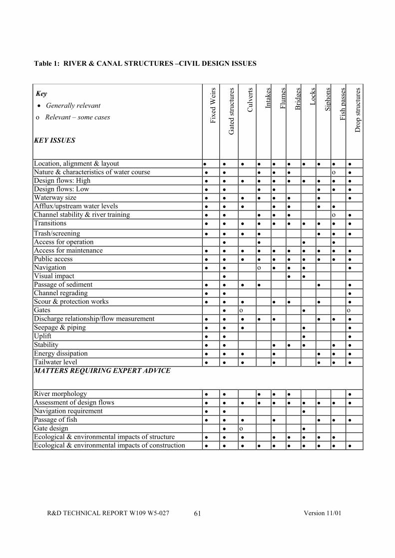
R&D TECHNICAL REPORT W109 W5-027 Version 11/0161
Table 1: RIVER & CANAL STRUCTURES –CIVIL DESIGN ISSUES
Key
• Generally relevant
o Relevant – some cases
KEY ISSUES
Fixe
d W
eirs
Gat
ed s
truct
ures
Cul
verts
Inta
kes
Flum
es
Brid
ges
Lock
s
Siph
ons
Fish
pas
ses
Dro
p st
ruct
ures
Location, alignment & layout • • • • • • • • • •Nature & characteristics of water course • • • • • o •Design flows: High • • • • • • • • • •Design flows: Low • • • • • • •Waterway size • • • • • • • •Afflux/upstream water levels • • • • • • •Channel stability & river training • • • • • o •Transitions • • • • • • • • • •Trash/screening • • • • • • •Access for operation • • • •Access for maintenance • • • • • • • • • •Public access • • • • • • • • • •Navigation • • o • • • •Visual impact • • •Passage of sediment • • • • • •Channel regrading • • •Scour & protection works • • • • • • •Gates • o • oDischarge relationship/flow measurement • • • • • • • •Seepage & piping • • • • •Uplift • • • •Stability • • • • • • •Energy dissipation • • • • • • •Tailwater level • • • • • • •MATTERS REQUIRING EXPERT ADVICE
River morphology • • • • • •Assessment of design flows • • • • • • • • • •Navigation requirement • • •Passage of fish • • • • • • •Gate design • o •Ecological & environmental impacts of structure • • • • • • • •Ecological & environmental impacts of construction • • • • • • • • • •

R&D TECHNICAL REPORT W109 W5-027 Version 11/0162
11.4 References
Topic Reference
Basic concepts 3, 5, 6, 7, 8, 10, 12,14
Types of structures 1, 2, 4, 6, 9, 11, 13,14, 15, 16, 17, 18,
1. Ackers, P et al (1978) Weirs and flumes forflow measurement J. Wiley & Sons;Chichester
2. Avery, P (Ed), (1989), Sediment control atintakes BHR Group, Cranfield.
3. Bos MG (Ed), (1990), Dischargemeasurement structures InternationalInstitute for Land Reclamation &Improvement (ILRI), Wageningen, TheNetherlands.
4. Bouvard, M (1992) Mobile barrages andintakes on sediment transporting riversIAHR Monograph, AA Balkema; Rotterdam
5. Brandon, T W (Ed), (1989), Riverengineering part I, design principles, WaterPractice Manual No 7, The Institution ofWater & Environmental Management,London
6. Brandon, T W (Ed), (1989), Riverengineering part II, structures and coastaldefence works, Water Practice Manual No 8,The Institution of Water & Environmental Management, London
7. Breusers, H N C and Raudkivi, A J, (1994),Scouring, IAHR Hydraulic StructuresDesign Manual No 2, AA Balkema,Rotterdam.
8. Chow, V T (1959) Open-channel hydraulics,McGraw-Hill; Kogakusha
9. Farraday, R V and Charlton, F G, (1983),Hydraulic factors in bridge design, ThomasTelford Ltd, London
10.Henderson, F M (1966) Open-channel flowMacmillan; New York
11. Lewin, J (1995) Hydraulic gates and valvesThomas Telford Ltd; London
12. Miller, D S (Ed) (1994) Dischargecharacteristics, IAHR Hydraulic StructuresDesign Manual No 8, AA Balkema,Rotterdam.
13. Neill, C R (Ed) (1973) Guide to bridgehydraulics Roads & TransportationAssociation of Canada, University ofToronto Press.
14. Novak, P et al (1996) Hydraulic structures E& F N Spon; London
15. Ramsbottom, D et al (1997) Culvert design manual CIRIA Report 168, CIRIA; London
16. Raudkivi, A J (1993), Sedimentation:exclusion and removal of sediment fromdiverted water, IAHR Hydraulic StructuresDesign Manual No 6, AA Balkema,Rotterdam.
17. Technical Advisory Committee on WaterDefences Guide for the design of river dikes:vol 1 - upper river area, (1991), TechnicalAdvisory Committee on Water Defences,Centre for Civil Engineering Research &Codes, (CUR), Gouda, The Netherlands.
18. USBR (1978) Design of small canalstructures US Department of the Interior,Bureau of Reclamation
R&D TECHNICAL REPORT W109 W5-027 Version 11/0163
12. RIVER & CANAL STRUCTURES (M&E ASPECTS)
12.1 Scope of Chapter
There are a number of types of river and canalinstallations and structures that involve plant andother mechanical, electrical and instrumentationequipment. This chapter covers such plant whichincludes:
• gates and gate operating equipment;
• pumping equipment;
• inflatable weirs;
• trash screens and booms; and
• fish deterrent devices.
In many cases such equipment involves theprovision of electrical power, with either local orremote control and instrumentation.
Generally, specialist advice should be soughtwith regard to the design specification and choiceof all such equipment, but it is important that thepotential problems and requirements of the plantare recognised.
12.2 Power Supplies
Many installations require electrical power foroperation, monitoring and control, auxiliaryservices, lighting etc. Generally this requires alink to the supply system, for which suitableexpertise and advice must be sought. In somecases, emergency standby generation may berequired, or direct diesel-powered operation ofthe installation.
For remote monitoring stations, solar-poweredinstrumentation should be considered.
12.3 Control and Instrumentation
Many installations now have partial or fullautomation, with telemetry and SupervisoryControl and Data System (SCADA) systemsgiving remote control, monitoring of operationand notification of failures. Flood control systemsmay include automatic operation, controlledremotely from a central logic unit.
Instrumentation would typically cover monitoringof flows, water levels, gate positions, pumpoperating pressures and power consumption.
More sophisticated monitoring of equipmentperformance is also available.
Consideration should be given to:
• the security of installations;
• accuracy and reliability requirements;
• lightning protection;
• the risks of flooding; and
• back-up systems for critical installations.
Consideration should also be given to the methodof communication and its compatibility withexisting facilities, including maintenance andspares arrangements. Methods include hardwiredlinks, telephone and (increasingly) radio. Thecosts of optical fibre links are unlikely to bejustified.
12.4 Types of Installation
12.4.1 Gates
Gates are an essential part of many installationsand range from major one-off designs,specifically tailored to the particular requirementsof a site, to small penstocks, sluice gates and flapvalves, that can be purchased as standard items.
In the fluvial environment, gates are used for:
• river level control;
• flood release and storage control;
• drainage releases;
• tidal back-flow control; and
• navigation lockage.
There are many different types of gates, and thebest choice for a site depends on its particularrequirements with regard to:
• flow control requirements;
• operation and control (e.g. whether manual,remote or automatic, frequency, accuracyetc);
• maintenance considerations;
• visual impact;
R&D TECHNICAL REPORT W109 W5-027 Version 11/0164
• passage of fish;
• navigation requirements; and
• cost.
Other matters that must be considered in thedesign of the gate and its installation mayinclude:
• safety to the public and to operation andmaintenance staff;
• materials (strength, durability, impact on theenvironment, etc);
• methods of lifting and control;
• power supplies under both normal andemergency operation;
• ease of handling and maintenance;
• repair and maintenance of protective coat-ings;
• sealing requirements;
• suppression of flow-induced vibration;
• instrumentation and control; and
• traditional local types of gate and rivercontrol (e.g. the use of paddle and rymergates on the upper Thames).
12.4.2 Pumping Plant
Pumping plant is most commonly required in thiscontext for drainage control, but may also beused for flood alleviation and for water transfers.Most installations have plant permanently inplace, but in some installations, mobile plant maybe brought in and installed for a temporarypurpose.
There are many different types and designs ofpump and the choice must be determined withregard to:
• the pumping requirements - the ranges ofhead and flow, frequency of operation andduration;
• whether the installation is to be manned orautomatic;
• the use or otherwise of submersible pumps;
• the use of weather-proofed pumps or theneed for a building;
• the passage of sediment and trash;
• cost (both capital and recurring);
• reliability;
• ease of maintenance and replacement; and
• the need or otherwise for variable speedmotors.
Particular matters to be considered in the designof a pumping installation include:
• the hydraulics of the sump and approach tothe pump;
• the avoidance of swirl at the pump inlets;
• inlet screening both for trash and fish;
• access for operation and maintenance andpossible provision of lifting equipment;
• flammable gases;
• ventilation;
• power supply (electrical, diesel or diesel-electric) including standby provision;
• control and instrumentation requirements;
• visual impact; and
• safety and security for both the public andoperations staff.
12.4.3 Inflatable weirs
Inflatable weirs have not been widely used in theUK to date, but are increasingly found elsewhere.They may be used in place of a gated barragewhere there is a need to minimise afflux duringfloods. They require a compressed air or pumpedwater system to inflate. Advice should be soughtfrom the manufacturers regarding security andcontrol requirements.
12.4.4 Trash Screens and Booms
Trash screens are used to prevent the passage offloating and semi-buoyant debris into locations,such as culverts, intakes and pumping stations,where it could cause a blockage or damageequipment. Similar structures are also used forother applications, including the control of fishmovement from reach to reach and as securityand safety grilles across culverts, siphons, intakesand outfalls.
R&D TECHNICAL REPORT W109 W5-027 Version 11/0165
Mechanically-raked screens are not common, butthere are some occasions where they may berequired to protect critical downstream culverts,bridges or waterways in sensitive locations fromhigh trash loads. Generally, the rakingmechanism would be a proprietary installationand advice should be sought from themanufacturers.
Considerations affecting trash screens andmechanically-raked screens include:
• vulnerability to blockage, particularly duringtimes of weed cutting;
• frequency of clearing required;
• safety of operatives carrying out manualraking;
• security and public safety, includingunauthorised access;
• access for vehicles to mechanically-rakedscreens, the size of skip employed and noisenuisance in residential areas;
• the proven efficacy of the selected design;and
• the risks of mechanical plant breakdown,hydraulic fluid spills etc.
In some locations a possible alternative to a trashscreen, whether manually or mechanically raked,is a floating boom, which uses the water flowpast it to direct the floating debris to one side ofthe watercourse, from where it can be collectedand removed.
12.4.5 Fish Screens and Deter rents
The need for deterrents to fish entering intakesand their direction towards fish passes hasencouraged the development of a number oftypes of device for use in the fluvialenvironment. These include:
• air bubble screens;
• acoustic devices;
• lighting; and
• current deflection devices.
The choice of type and its detailed design andsiting requires specialist advice and is a functionnot only of the site geometry and flow régimesbut also of the species of fish to be deterred.
R&D TECHNICAL REPORT W109 W5-027 Version 11/0166
12.5 References
Topic Reference
Basic concepts 3, 4, 6, 8, 9
Type of installation 1,2,4,5,6,7,10,11, 12
Note: No references for control andinstrumentation are included in the listbelow. The technology is changingrapidly and any standard text presentednow would be very quickly out of date.
1. Carling, P A & Dobson, J H (1992) Fishpass design and evaluation; phase 1 initialreview National Rivers Authority, R&DNote 110
2. Lewin, J (1995) Hydraulic gates and valves(in free surface flow and submerged outlets),Thomas Telford; London
3. MAFF (1984) Fish pass design - criteria forthe design and approval of fish passes andother structures to facilitate the passage ofmigratory fish in rivers fisheries ResearchTechnical Report No 78
4. National Rivers Authority (1992) Diversionand entrapment of fish at water intakes andoutfalls Report 1 National Rivers Authority
5. National Rivers Authority (1995) Pumpingstations - efficiency of operation and cost fora design life span - survey of pumpingstations and design philosophy R&D Project363
6. National Rivers Authority (1995) Pumpingstations - efficiency of operation and cost fora design life span - maintenance practices,organisation and energy saving initiativesR&D Project 363/2/NW
7. National Rivers Authority (1995) Pumpingstation design manual - final report R&DNote 471
8. National Rivers Authority (1992) Design andoperation of trash screens R&D project300/2/T,
9. Naudascher, E et al (1994) Flow inducedvibrations: an engineering Guide A ABalkema, Rotterdam
10. Prosser, M J (1977) The hydraulic design ofpump sumps and intakes CIRIA; London
11. Prosser, M J (1992) Design of low-liftpumping stations for CIRIA
12. Sanks, R L (Ed) (1989) Pumping stationdesign, Butterworths; USA